EP2139604B1 - Organe de pulverisation, dispositif de projection comportant un tel organe, installation de projection et methode de nettoyage d'un tel organe - Google Patents
Organe de pulverisation, dispositif de projection comportant un tel organe, installation de projection et methode de nettoyage d'un tel organe Download PDFInfo
- Publication number
- EP2139604B1 EP2139604B1 EP08805488.7A EP08805488A EP2139604B1 EP 2139604 B1 EP2139604 B1 EP 2139604B1 EP 08805488 A EP08805488 A EP 08805488A EP 2139604 B1 EP2139604 B1 EP 2139604B1
- Authority
- EP
- European Patent Office
- Prior art keywords
- spraying
- cup
- product
- bowl
- volume
- Prior art date
- Legal status (The legal status is an assumption and is not a legal conclusion. Google has not performed a legal analysis and makes no representation as to the accuracy of the status listed.)
- Active
Links
Images
Classifications
-
- B—PERFORMING OPERATIONS; TRANSPORTING
- B05—SPRAYING OR ATOMISING IN GENERAL; APPLYING FLUENT MATERIALS TO SURFACES, IN GENERAL
- B05B—SPRAYING APPARATUS; ATOMISING APPARATUS; NOZZLES
- B05B3/00—Spraying or sprinkling apparatus with moving outlet elements or moving deflecting elements
- B05B3/02—Spraying or sprinkling apparatus with moving outlet elements or moving deflecting elements with rotating elements
- B05B3/10—Spraying or sprinkling apparatus with moving outlet elements or moving deflecting elements with rotating elements discharging over substantially the whole periphery of the rotating member
- B05B3/1007—Spraying or sprinkling apparatus with moving outlet elements or moving deflecting elements with rotating elements discharging over substantially the whole periphery of the rotating member characterised by the rotating member
- B05B3/1014—Spraying or sprinkling apparatus with moving outlet elements or moving deflecting elements with rotating elements discharging over substantially the whole periphery of the rotating member characterised by the rotating member with a spraying edge, e.g. like a cup or a bell
-
- B—PERFORMING OPERATIONS; TRANSPORTING
- B05—SPRAYING OR ATOMISING IN GENERAL; APPLYING FLUENT MATERIALS TO SURFACES, IN GENERAL
- B05B—SPRAYING APPARATUS; ATOMISING APPARATUS; NOZZLES
- B05B15/00—Details of spraying plant or spraying apparatus not otherwise provided for; Accessories
- B05B15/50—Arrangements for cleaning; Arrangements for preventing deposits, drying-out or blockage; Arrangements for detecting improper discharge caused by the presence of foreign matter
- B05B15/55—Arrangements for cleaning; Arrangements for preventing deposits, drying-out or blockage; Arrangements for detecting improper discharge caused by the presence of foreign matter using cleaning fluids
-
- B—PERFORMING OPERATIONS; TRANSPORTING
- B05—SPRAYING OR ATOMISING IN GENERAL; APPLYING FLUENT MATERIALS TO SURFACES, IN GENERAL
- B05B—SPRAYING APPARATUS; ATOMISING APPARATUS; NOZZLES
- B05B3/00—Spraying or sprinkling apparatus with moving outlet elements or moving deflecting elements
- B05B3/02—Spraying or sprinkling apparatus with moving outlet elements or moving deflecting elements with rotating elements
- B05B3/10—Spraying or sprinkling apparatus with moving outlet elements or moving deflecting elements with rotating elements discharging over substantially the whole periphery of the rotating member
- B05B3/1057—Spraying or sprinkling apparatus with moving outlet elements or moving deflecting elements with rotating elements discharging over substantially the whole periphery of the rotating member with at least two outlets, other than gas and cleaning fluid outlets, for discharging, selectively or not, different or identical liquids or other fluent materials on the rotating element
-
- B—PERFORMING OPERATIONS; TRANSPORTING
- B05—SPRAYING OR ATOMISING IN GENERAL; APPLYING FLUENT MATERIALS TO SURFACES, IN GENERAL
- B05B—SPRAYING APPARATUS; ATOMISING APPARATUS; NOZZLES
- B05B3/00—Spraying or sprinkling apparatus with moving outlet elements or moving deflecting elements
- B05B3/02—Spraying or sprinkling apparatus with moving outlet elements or moving deflecting elements with rotating elements
- B05B3/10—Spraying or sprinkling apparatus with moving outlet elements or moving deflecting elements with rotating elements discharging over substantially the whole periphery of the rotating member
- B05B3/1064—Spraying or sprinkling apparatus with moving outlet elements or moving deflecting elements with rotating elements discharging over substantially the whole periphery of the rotating member the liquid or other fluent material to be sprayed being axially supplied to the rotating member through a hollow rotating shaft
-
- B—PERFORMING OPERATIONS; TRANSPORTING
- B05—SPRAYING OR ATOMISING IN GENERAL; APPLYING FLUENT MATERIALS TO SURFACES, IN GENERAL
- B05B—SPRAYING APPARATUS; ATOMISING APPARATUS; NOZZLES
- B05B5/00—Electrostatic spraying apparatus; Spraying apparatus with means for charging the spray electrically; Apparatus for spraying liquids or other fluent materials by other electric means
- B05B5/025—Discharge apparatus, e.g. electrostatic spray guns
- B05B5/04—Discharge apparatus, e.g. electrostatic spray guns characterised by having rotary outlet or deflecting elements, i.e. spraying being also effected by centrifugal forces
- B05B5/0403—Discharge apparatus, e.g. electrostatic spray guns characterised by having rotary outlet or deflecting elements, i.e. spraying being also effected by centrifugal forces characterised by the rotating member
- B05B5/0407—Discharge apparatus, e.g. electrostatic spray guns characterised by having rotary outlet or deflecting elements, i.e. spraying being also effected by centrifugal forces characterised by the rotating member with a spraying edge, e.g. like a cup or a bell
Definitions
- the present invention relates to a spraying member for a rotary projector coating product, and a projection device equipped with such a spraying member and a coating product spraying installation incorporating such a device.
- the invention also relates to a method of cleaning such a spraying member.
- Stack stacks are known from the prior art to increase the spraying rate of liquid products.
- FR-A-1363681 discloses a liquid product spraying plant consisting of a jet liquid spraying member, at least one rotating spindle rotating member disposed thereunder, and means for varying the amount of product to be dispensed. sprayed dispensed to the rotary spray member, varying the distance between the nozzle and the disk or disks.
- FR-A-1363681 proposes to use two or more ridge spraying devices.
- a technical problem posed by the "multi-bowls" spraying means is the cleaning of the external surface of the internal bowls or bowls, soiled during the spraying where the rotation of the member creates a depression between the bowls which causes the deposition of droplets on an outer surface. This surface is difficult to reach by the solvent during rinsing.
- FR-A-2 170 940 discloses a spraying member for spraying two separate products with two separate feed means. Such supply means, however, do not allow to simultaneously feed the two distribution surfaces of the spray member. In addition, the construction of such a spraying member is relatively complex and detrimental to the balance and compactness of this organ.
- US-A-5,894,993 discloses a spray member comprising a single internal coating material distribution surface and an annular guide for guiding solvent to clean the outer surface of the spray member.
- the flow of coating material sprayed by such a spraying member is relatively limited because there is only one spray edge.
- the invention intends to remedy more particularly by providing a compact and compact multi-bowl spraying device whose geometry is such that the cleaning of the external surface of its internal bowl is facilitated.
- the subject of the invention is a spraying member for a rotary coating product projector, said spraying member comprising at least one external bowl and an internal bowl, each bowl defining a spray edge, an internal surface of distribution and an outer surface the inner bowl is being arranged radially inside the outer bowl, then and in that a volume defined between the inner surface of the outer bowl and the outer surface of the inner bowl has a decreasing thickness between a first value, taken at a cleaning product inlet area in the volume, and a second value, taken at the spray edge of the outer bowl, the spray member being characterized in that comprises central supply means of the internal surfaces of distribution of the bowls.
- the volume defined between the inner surface of the outer bowl and the outer surface of the inner bowl has a passage section which narrows in the direction of progression of the cleaning product towards the spraying edge of the bowl. external. Indeed, its thickness, which corresponds to the distance, taken perpendicularly to a median of this volume, between the inner surface of the outer bowl and the outer surface of the inner bowl, allows to control the distribution of the cleaning product in this volume.
- the speed of the product increases between the bowls at the same time as the diameter of the bowls.
- the pressure of the product between the bowls tends to decrease as the diameter of the bowls increases, i.e. in the direction of flow of the product.
- the passage section is to be reduced, which provides the invention.
- the passage section is to be reduced, which provides the invention.
- the cleaning of these internal and external surfaces is thus optimized.
- the central supply means can simultaneously feed the two internal distribution surfaces with a compact and balanced construction of the spray member
- the invention also relates to a coating product spraying device which comprises a spraying member as mentioned above as well as means for driving this rotating member and means for supplying this member with a coating product. .
- the spraying member comprises a splitter provided with an orifice
- the diameter of this orifice is advantageously less than or equal to the internal diameter of the downstream end of the feed means of the feed product. coating.
- the invention also relates to a coating product projection installation which comprises, inter alia, at least one projection device as mentioned above.
- the invention relates to a method of cleaning a spraying member as mentioned above, this method comprising a step of gaving the volume defined between the inner surface of the outer bowl and the outer surface of the inner bowl product cleaning and / or air.
- this gavage uses for this gavage a cleaning product or a mixture of cleaning products and foaming air.
- the projector P represented at figure 1 is fed with coating material from one or more unrepresented sources and moved, for example with a substantially vertical movement represented by the double arrow F 1 , facing objects O to be coated within a facility I of coating of these objects.
- the projector comprises an air turbine of which only the rotor 1 is visible on the figure 1 , this rotor being rotated about an axis X 1 -X ' 1 .
- a body 2 fixed with respect to the axis X 1 -X ' 1 , surrounds the rotor 1 and is itself isolated from the outside by a cover 3.
- An annular support 4 made of magnetic material, for example stainless steel magnetic, is mounted on the front face 21 of the body 2, this support being provided with an annular groove centered on the axis X 1 -X ' 1 and in which is disposed an annular magnet 41.
- An injector 5 coating product is aligned on the axis X 1 -X ' 1 .
- a spraying member 10 is mounted on a projector P and forms a frustoconical surface 10A intended to cooperate with a frustoconical surface 1A of the rotor 1 to rotate the spraying member 10 and the rotor 1 in rotation.
- a ring 13 of ferromagnetic material is mounted on the spraying member 10, so that an attraction force F 2 due to the magnet 41 is exerted on the ring 13, which firmly plates the surfaces 10A and 1A against each other, while an air gap E is formed between the ring 13 and the support 4. It is made here application of the technical education of FR-A-2887472 .
- the spraying member 10 comprises two bowls 100 and 200, of different diameters and geometries.
- the outer bowl 100 is provided with a spray edge 101, a product distribution surface 102 and an outer surface 103.
- the injector 5 brings the liquid product to be sprayed to the bowl 100.
- the bowl 100 In the bowl 100 is fixed an internal bowl 200, by screwing, with a hub 6.
- the inner bowl 200 is immobilized on the hub 6 by any appropriate means, for example by gluing.
- the hub 6 is screwed, thanks to a thread 64, into a threaded portion 104 of the bowl 10.
- the two bowls 100 and 200 are thus assembled by being removable with respect to one another.
- a male centering cone is provided on the bowl 200, while a corresponding female centering cone is provided on the bowl 100. This ensures a permanent relative centering of these bowls.
- the bowl 200 can be fixed on the bowl 100 by other mechanical means, for example in force.
- the hub 6 is provided with pads 61 between which there are openings 62 here in the form of beans, for the passage of the coating product of the injector 5 to the inner surface 102 of the bowl 100.
- the bowl 200 is provided with a spray edge 201, a product distribution surface 202 and an outer surface 203.
- D 101 and D 201 denote respectively the diameters of the edges 101 and 201.
- the value of D 101 is slightly greater than that of D 201 . More precisely, D 101 is greater than X at Y% relative to D201.
- D 101 may be 63.5 mm, while D 201 is 65 mm.
- the distributor 7 is provided with pads 71 between which are formed openings 72, here in the form of beans, for the passage of the coating product to the inner surface 202 of the bowl 200.
- An insert 8 mounted in the bowl 200 defines an orifice 81 aligned on the central axis X 10 -X '10 of the member 10 which forms an axis of symmetry of the surfaces 102, 103, 202 and 203.
- the insert 8 protrudes from the rear face 206 of the bowl 200 intended to be turned towards the injector 5.
- the portion 82 of the insert 8, which protrudes with respect to the surface 206 has a convergent inner surface in direction of the ridge 201 and can be considered as a funnel.
- the portion 82 of the insert 8 projecting from the surface 206 may be in the form of "inverted funnel", with a diverging outer surface in the direction of the ridge 201 and a cylindrical inner surface with a circular base.
- the insert 8 may not protrude from the surface 206.
- the three forms of the insert 8 contemplated above make it possible to influence the distribution of the product between the flow paths formed by the surfaces 102 and 202 of the two bowls. Different types of bowls can therefore be provided, with inserts 8 of different geometry.
- edges 101 and 201 are not in the same plane, they are offset axially with respect to each other, the edge 101 being set back relative to the edge 201, in order to avoid as much as possible jets of pulverized product recombine, that is to say, mingle with each other.
- indented is meant that the edge 101 is further away from the objects O than the edge 201. It is necessary to separate as much as possible the jets of coating product from the edges 101 and 201. Indeed, if the These jets recombine, so the size of the droplets increases, while a uniform spray requires droplets as fine as possible.
- the distance d 1 of withdrawal of the edge 101 with respect to the edge 201 may be 10 millimeters for a bowl whose edge 201 has a diameter of the order of 65 mm.
- the distance d 1 represents more than 1% of the diameter D 201 of the edge 201, which ensures a good separation of the product jets without axially lengthening the bowl too much. The greater the shrinkage, the less jets of sprayed product recombine.
- the inner surface 102 of the bowl 100 and the outer surface 203 of the bowl 200 define a volume V 1 between them.
- the difference measured between the two bowls 100 and 200 is perpendicular to a median M between the generatrices of the surfaces 102 and 203, that is to say the thickness of the volume V 1 .
- the thickness e is equal to the distance between the inner surface 102 and the outer surface 203.
- the thickness ea for a given position along the axis X 10 -X '10 , the same value regardless of the angular sector around the axis X 10 -X' 10 in which it is measured, which is visible at the figure 4 where the thickness e is uniform.
- e 1 the value of the thickness e measured at the level of the entry zone of the product in the volume V 1 , at the height of the rear face 63 of the assembly consisting of the bowl 200, of the upper part of the hub. 6 and the distributor 8.
- e 2 the value of the thickness e measured at the edge 101 of the bowl 100.
- the thickness e decreases continuously from e 1 to e 2 , e 2 being less than e 1 .
- e 1 may be 2 mm while e 2 is a few tenths of a millimeter.
- the decrease of the value of e between the values e 1 and e 2 has the effect that the section S of product passage in the volume V 1 , which is annular as shown in FIG. figure 4 , has an area that decreases between the input area and the output area of this volume.
- the decrease in the value of the thickness e between the values e 1 and e 2 can take place non-continuously, this thickness being able, for example, to be constant over a part of the volume V 1 .
- the spraying member 10 rotates about the axis X 1 -X ' 1 .
- the two bowls 100 and 200 are integral and rotate at the same time, at the same speed.
- the coating product is fed through the injector 5, taps against the rear face 63 of the assembly consisting of the bowl 200, the upper part of the hub 6 and possibly the projecting portion 82 of the distributor 8, and spreads on the inner surface of the bowl 100, to the spraying edge 101 where the liquid splits into fine droplets.
- a fraction of the coating product supplied by the injector 5 continues its path directly into the distributor 8 through the orifice 81.
- This fraction is defined both by the geometry of the distributor 8, in particular the diameter inside of the orifice 81, and by the flow of coating product.
- This fraction taps against the rear face 73 of the distributor 7 and spreads on the inner surface of the bowl 200, to the spray edge 201 where the liquid splits into fine droplets.
- air-solvent trains are conveyed by the injector 5, sized with a flow rate for filling the volume V 1 .
- the air and solvent trains follow the same paths as the coating product, from the injector 5 to the edges 101 and 201.
- the reduction of the gap between the bowls 100 and 200 of e 1 to e 2 has the effect of compensating for a decrease in pressure due to the centrifugal force and of slightly compressing the rinsing liquid to allow the force-feeding of the volume V 1 during rinsing of the spray member, thereby rinsing the surface 102 and the surface 203 at the same time.
- the injection of cleaning product can properly clean not only the inner surfaces 102 and 202, but also the surface 203.
- the air-solvent trains can create a foam, by air dispersion in a liquid, which increases the cleaning efficiency. It is also possible that the cleaning product is itself a foaming product. In this case, the compression effect obtained due to the decrease in the thickness e is exerted on the air bubbles present in the dispersion or in the foaming product, which gives rise to a "scraping" effect of the bubbles. air on surfaces 102 and 203.
- the bowl 100 is pierced with a series of orifices 150 which each extend between an inlet 150A located on the surface 103 of the bowl 100 and an outlet 150B located on the surface 102.
- the orifices 150 are cylindrical, each centered on one axis X 150 oblique to the axis X 10 -X '10 .
- the orifices 150 make it possible to generate an air intake from the outside towards the volume V 1 . These holes are easy to achieve because they can be drilled in the bowl 100 before mounting the bowl 200.
- the invention has been shown with a spraying member 10 having two bowls. It is also applicable with a stack of three or more successive bowls connected in series ended by mounting a dispenser on the innermost bowl.
- volumes V 1 ,..., V n-1 may be defined by analogy with the embodiment shown, with different geometries, each volume having a decreasing radial thickness, from its zone of entry to its zone. Release.
- the invention has been shown with a spraying member 10 attached to the rotor 1 by magnetic effect. It is also applicable with a spraying member fixed by any other means, in particular screwed.
- the invention has been shown with bowls 100 and 200 removable. It is also applicable with an organ whose bowls are not removable, for example monoblocks.
- the invention has been represented with a bowl 100 whose edge 101 has a diameter D 101 greater than the diameter D 201 of the edge 201 of the bowl 200.
- the invention is however applicable to the case where the diameter D 101 is equal to slightly smaller than the diameter D 201 , which is possible because of the withdrawal d 1 of the edge 101 relative to the edge 201.
Landscapes
- Nozzles (AREA)
- Application Of Or Painting With Fluid Materials (AREA)
- Spray Control Apparatus (AREA)
- Cleaning By Liquid Or Steam (AREA)
Description
- La présente invention concerne un organe de pulvérisation pour un projecteur rotatif de produit de revêtement, ainsi qu'un dispositif de projection équipé d'un tel organe de pulvérisation et une installation de projection de produit de revêtement incorporant un tel dispositif. L'invention concerne également une méthode de nettoyage d'un tel organe de pulvérisation.
- La pulvérisation conventionnelle par bols tournants est utilisée pour l'application sur des objets à revêtir, tels que des carrosseries de véhicules automobiles, des apprêts, de la première couche de base et des vernis, avec des débits de peinture compris entre 100 et 500cc/min. Afin de diminuer les investissements liés à l'installation et au fonctionnement des lignes de peinturage, le marché automobile tend à réduire leur longueur ainsi que le nombre de robots de pulvérisation installés sur ces lignes. Ainsi, les pulvérisateurs destinés à être montés sur ces robots doivent être capables de pulvériser des produits de revêtement avec des débits élevés.
- Il est connu de l'art antérieur des empilements de bols en vue d'augmenter le débit de pulvérisation de produits liquides. Par exemple,
FR-A-1363681 FR-A-1363681 - Un problème technique posé par les organes de pulvérisation « multi-bols » est le nettoyage de la surface externe du ou des bols internes, salie pendant la pulvérisation où la rotation de l'organe crée une dépression entre les bols qui entraîne le dépôt de gouttelettes sur une surface externe. Cette surface est difficilement atteignable par le solvant lors du rinçage.
-
FR-A-2 170 940 -
US-A-5 894 993 décrit un organe de pulvérisation comprenant une seule surface interne de répartition de produit de revêtement et un guide annulaire destiné à guider du solvant pour nettoyer la surface externe de l'organe de pulvérisation. Cependant, le débit de produit de revêtement pulvérisé par un tel organe de pulvérisation est relativement limité, car il n'y a qu'une arête de pulvérisation. - C'est à ces inconvénients qu'entend plus particulièrement remédier l'invention en proposant un organe de pulvérisation multi-bols équilibré et compact dont la géométrie est telle que le nettoyage de la surface externe de son bol interne est facilité.
- A cet effet, l'invention a pour objet un organe de pulvérisation pour un projecteur rotatif de produit de revêtement, ledit organe de pulvérisation comprenant au moins un bol externe et un bol interne, chaque bol définissant une arête de pulvérisation, une surface interne de répartition et une surface externe le bol interne est étant disposé radialement à l'intérieur du bol externe, alors et en ce qu'un volume défini entre la surface interne du bol externe et la surface externe du bol interne a une épaisseur décroissante entre une première valeur, prise au niveau d'une zone d'entrée de produit de nettoyage dans le volume, et une deuxième valeur, prise au niveau de l'arête de pulvérisation du bol externe, l'organe de pulvérisation étant caractérisé en ce qu'il comprend des moyens d'alimentation centrale des surfaces internes de répartition des bols.
- Grâce à l'invention, le volume défini entre la surface interne du bol externe et la surface externe du bol interne a une section de passage qui se rétrécit dans le sens de progression du produit de nettoyage en direction de l'arête de pulvérisation du bol externe. En effet, son épaisseur, qui correspond à la distance, prise perpendiculairement à une médiane de ce volume, entre la surface interne du bol externe et la surface externe du bol interne, permet de contrôler la répartition du produit de nettoyage dans ce volume. Sous l'effet de la force centrifuge, la vitesse du produit augmente entre les bols en même temps que le diamètre des bols. De ce fait, la pression du produit entre les bols a tendance à diminuer, alors que le diamètre des bols augmente, c'est-à-dire dans le sens d'écoulement du produit. Pour maintenir un niveau suffisant de pression du produit jusqu'à la sortie du volume, la section de passage est à diminuer, ce que prévoit l'invention. Ainsi, il est possible de gaver ce volume en produit de nettoyage ou avec un mélange de produit de nettoyage et d'air, ce qui permet au produit de nettoyage de lécher à la fois la surface interne du bol externe et la surface externe du bol interne. Le nettoyage de ces surfaces internes et externes est ainsi optimisé. De plus, les moyens d'alimentation centrale permettent d'alimenter simultanément les deux surfaces internes de répartition avec une construction compacte et équilibrée de l'organe de pulvérisation
- Selon des aspects avantageux mais non obligatoires de l'invention, un tel organe de pulvérisation peut incorporer une ou plusieurs des caractéristiques suivantes :
- Ces moyens d'alimentation centrale comprennent un répartiteur pourvu d'un orifice aligné sur un axe de symétrie des surfaces internes et externes des bols, cet orifice étant destiné à l'alimentation en produit de revêtement de la surface interne de répartition du bol interne
- Les moyens d'alimentation comprennent un déflecteur monté dans le bol interne en regard d'une partie centrale de la surface interne de la répartition
- Le rapport de la deuxième valeur de l'épaisseur du volume sur la première valeur de cette épaisseur est inférieur à 0,9, de préférence à 0,5, de préférence encore de l'ordre 0,4,
- L'arête de pulvérisation du bol externe est axialement en retrait par rapport à l'arête de pulvérisation du bol interne, d'une distance supérieure à 1 % du diamètre de l'arête de pulvérisation du bol interne.
- Des orifices d'entrée d'air vers le volume précité peuvent être prévus sur le bol externe.
- L'invention concerne également un dispositif de projection de produit de revêtement qui comprend un organe de pulvérisation tel que mentionné ci-dessus ainsi que des moyens d'entraînement de cet organe en rotation et des moyens d'alimentation de cet organe en produit de revêtement.
- Dans le cas où l'organe de pulvérisation comprend un répartiteur pourvu d'un orifice, comme mentionné ci-dessus, le diamètre de cet orifice est avantageusement inférieur ou égal au diamètre interne de l'extrémité aval des moyens d'alimentation en produit de revêtement.
- L'invention concerne également une installation de projection de produit de revêtement qui comprend, entre autres, au moins un dispositif de projection tel que mentionné ci-dessus.
- Enfin, l'invention concerne une méthode de nettoyage d'un organe de pulvérisation tel que mentionné ci-dessus, cette méthode comprenant une étape consistant à gaver le volume défini entre la surface interne du bol externe et la surface externe du bol interne en produit de nettoyage et/ou en air.
- Avantageusement, on utilise pour ce gavage un produit de nettoyage ou un mélange de produits de nettoyage et d'air moussant.
- L'invention sera mieux comprise et d'autres avantages de celle-ci apparaîtront plus clairement à la lumière de la description qui va suivre, donnée uniquement à titre d'exemple et faite en référence aux dessins annexés dans lesquels :
- la
figure 1 est une coupe longitudinale de principe d'un projecteur de produit de revêtement conforme à l'invention utilisé dans une installation conforme à l'invention et incorporant un organe de pulvérisation conforme à l'invention ; - la
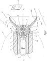
figure 2 est une coupe axiale de l'organe de pulvérisation de lafigure 1 ; - la
figure 3 est une vue en perspective, avec arrachement partiel, de l'organe de lafigure 2 - la
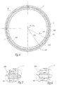
figure 4 est une section selon la ligne IV-IV à lafigure 2 - la
figure 5 est une vue à plus grande échelle du détail V à lafigure 2 et - la
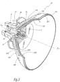
figure 6 est une vue analogue à lafigure 5 pour un second mode de réalisation de l'invention. - Le projecteur P représenté à la
figure 1 est alimenté en produit de revêtement à partir d'une ou plusieurs sources non représentées et déplacé, par exemple avec un mouvement essentiellement vertical représenté par la double flèche F1, en regard d'objets O à revêtir au sein d'une installation I de revêtement de ces objets. Le projecteur comprend une turbine à air dont seul le rotor 1 est visible sur lafigure 1 , ce rotor étant entraîné en rotation autour d'un axe X1-X'1. - Un corps 2, fixe par rapport à l'axe X1-X'1, entoure le rotor 1 et est lui-même isolé de l'extérieur par un capot 3. Un support annulaire 4 en matériau magnétique, par exemple en acier inox magnétique, est monté sur la face avant 21 du corps 2, ce support étant pourvu d'une gorge annulaire centrée sur l'axe X1-X'1 et dans laquelle est disposé un aimant annulaire 41. Un injecteur 5 de produit de revêtement est aligné sur l'axe X1-X'1.
- Un organe de pulvérisation 10 est monté sur projecteur P et forme une surface tronconique 10A destinée à coopérer avec une surface tronconique 1A du rotor 1 pour solidariser en rotation l'organe de pulvérisation 10 et le rotor 1. Pour garantir un appui efficace des surfaces 10A et 1A l'une contre l'autre et une immobilisation relative à la façon d'un cône Morse, une bague 13 en matériau ferromagnétique est montée sur l'organe de pulvérisation 10, de telle sorte qu'un effort d'attraction F2 dû à l'aimant 41 s'exerce sur la bague 13, ce qui plaque fermement les surfaces 10A et 1A l'une contre l'autre, alors qu'un entrefer E est ménagé entre la bague 13 et le support 4. On fait ici application de l'enseignement technique de
FR-A-2887472 - L'organe de pulvérisation 10 comprend deux bols 100 et 200, de diamètres et de géométries différents.
- Le bol externe 100 est pourvu d'une arête de pulvérisation 101, d'une surface de répartition du produit 102 et d'une surface externe 103.
- L'injecteur 5 amène le produit liquide à pulvériser au bol 100.
- Dans le bol 100 est fixé un bol interne 200, par vissage, grâce à un moyeu 6. Le bol interne 200 est immobilisé sur le moyeu 6 par tout moyen approprié, par exemple par collage. Ensuite, le moyeu 6 est vissé, grâce à un filetage 64, dans une partie taraudée 104 du bol 10. Les deux bols 100 et 200 sont donc assemblés en étant démontables l'un par rapport à l'autre. Un cône de centrage mâle est prévu sur le bol 200, alors qu'un cône de centrage femelle correspondant est prévu sur le bol 100. Ceci permet d'assurer un centrage relatif permanent de ces bols.
- Le bol 200 peut être fixé sur le bol 100 par d'autres moyens mécaniques, par exemple en force.
- Le moyeu 6 est pourvu de plots 61 entre lesquels sont ménagées des ouvertures 62 ici en forme de haricots, pour le passage du produit de revêtement de l'injecteur 5 vers la surface interne 102 du bol 100.
- Le bol 200 est pourvu d'une arête de pulvérisation 201, d'une surface de répartition du produit 202 et d'une surface externe 203.
- On note respectivement D101 et D201 les diamètres des arêtes 101 et 201. La valeur de D101 est légèrement supérieure à celle de D201. Plus précisément D101 est supérieur de X à Y % par rapport à D201. Par exemple D101 peut valoir 63,5 mm, alors que D201 vaut 65 mm.
- Sur le bol 200 est fixé par vissage un distributeur/déflecteur 7. Ce distributeur 7 pourrait être fixé par d'autres moyens mécaniques. Le distributeur 7 est pourvu de plots 71 entre lesquels sont ménagées des ouvertures 72, ici en forme de haricots, pour le passage du produit de revêtement vers la surface interne 202 du bol 200.
- Un insert 8 monté dans le bol 200 définit un orifice 81 aligné sur l'axe central X10-X'10 de l'organe 10 qui forme un axe de symétrie des surfaces 102, 103, 202 et 203.
- L'insert 8 fait saillie par rapport à la face arrière 206 du bol 200 destinée à être tournée vers l'injecteur 5. La partie 82 de l'insert 8, qui fait saillie par rapport à la surface 206 a une surface interne convergente en direction de l'arête 201 et peut être considérée comme un entonnoir.
- En variante, comme représenté à la
figure 6 , la partie 82 de l'insert 8 en saillie par rapport à la surface 206 peut être en forme « d'entonnoir inversé », avec une surface externe divergente en direction de l'arête 201 et une surface interne cylindrique à base circulaire. - Selon une autre variante qui n'est pas représentée, l'insert 8 peut ne pas dépasser de la surface 206.
- Les trois formes de l'insert 8 envisagées ci-dessus permettent d'influer sur la répartition du produit entre les trajets d'écoulement formés par les surfaces 102 et 202 des deux bols. Différents types de bols peuvent donc être prévus, avec des inserts 8 de géométrie différentes.
- Les arêtes 101 et 201 ne sont pas dans le même plan, elles sont décalées axialement l'une par rapport à l'autre, l'arête 101 étant en retrait par rapport à l'arête 201, afin d'éviter au maximum que les jets de produit pulvérisé se recombinent, c'est-à-dire se mêlent l'un à l'autre. Par « en retrait », on entend que l'arête 101 est plus éloignée des objets O que l'arête 201. Il convient de séparer autant que possible les jets de produit de revêtement issus des arêtes 101 et 201. En effet, si les jets se recombinent, alors la taille des gouttelettes augmente, alors qu'une pulvérisation homogène demande des gouttelettes aussi fines que possible.
- Pour exemple, la distance d1 de retrait de l'arête 101 par rapport à l'arête 201 peut être de 10 millimètres pour un bol dont l'arête 201 a un diamètre de l'ordre de 65 mm. En pratique, la distance d1 représente plus de 1 % du diamètre D201 de l'arête 201, ce qui assure une bonne séparation des jets de produit sans allonger axialement le bol de façon trop importante. Plus ce retrait est important, moins les jets de produit pulvérisé se recombinent.
- La surface interne 102 du bol 100 et la surface externe 203 du bol 200 définissent entre elles un volume V1.
- On note e l'écart mesuré entre les deux bols 100 et 200 perpendiculairement à une médiane M entre les génératrices des surfaces 102 et 203, c'est-à-dire l'épaisseur du volume V1. L'épaisseur e est égale à la distance, entre la surface interne 102 et la surface externe 203. Compte tenu de la géométrie des surfaces 102 et 203 qui sont symétriques par rapport à l'axe X10-X'10, l'épaisseur e a, pour une position donnée le long de l'axe X10-X'10, la même valeur quel que soit le secteur angulaire autour de l'axe X10-X'10 dans lequel elle est mesurée, ce qui est visible à la
figure 4 où l'épaisseur e est uniforme. L'épaisseur e détermine la section S de passage du volume V1 qui a une aire égale à :
- On note e1 la valeur de l'épaisseur e mesurée au niveau de la zone d'entrée du produit dans le volume V1, à hauteur de la face arrière 63 de l'ensemble constitué du bol 200, de la partie supérieure du moyeu 6 et du répartiteur 8. On note e2 la valeur de l'épaisseur e mesurée au niveau de l'arête 101 du bol 100. L'épaisseur e diminue de manière continue de e1 à e2, e2 étant inférieure à e1. A titre d'exemple e1 peut valoir 2 mm alors que e2 vaut quelques dixièmes de millimètre.
- La décroissance de la valeur de e entre les valeurs e1 et e2 a pour effet que la section S de passage de produit dans le volume V1, qui est annulaire comme le montre la
figure 4 , a une aire qui décroît entre la zone d'entrée et la zone de sortie de ce volume. - En variante, la décroissance de la valeur de l'épaisseur e entre les valeurs e1 et e2 peut avoir lieu de façon non continue, cette épaisseur pouvant, par exemple, être constante sur une partie du volume V1.
- En pratique, les valeurs e1 et e2 sont choisies de telle sorte que leur rapport R = e1/e2 est inférieur à 0,9, de préférence à 0,5. Des résultats tout à fait satisfaisants ont été obtenus avec R de l'ordre de 0,4.
- Pendant la pulvérisation, l'organe de pulvérisation 10 tourne autour de l'axe X1-X'1. Les deux bols 100 et 200 sont solidaires et tournent en même temps, à la même vitesse. Le produit de revêtement est amené par l'injecteur 5, tape contre la face arrière 63 de l'ensemble constitué du bol 200, de la partie supérieure du moyeu 6 et éventuellement de la partie en saillie 82 du répartiteur 8, et s'étale sur la surface interne du bol 100, jusqu'à l'arête de pulvérisation 101 où le liquide se divise en fines gouttelettes. Au passage, les turbulences dans le volume V1 et la dépression, créée dans ce volume par l'accélération du produit entre les deux bols sous l'effet de la force centrifuge, entraînent des gouttelettes de produit de revêtement qui viennent se déposer sur et salir sensiblement toute la surface 203 jusqu'à l'arête 201.
- Une fraction du produit de revêtement amenée par l'injecteur 5 continue son chemin directement dans le répartiteur 8 à travers l'orifice 81. Cette fraction est définie à la fois par la géométrie du répartiteur 8, notamment le diamètre intérieur de l'orifice 81, et par le débit de produit de revêtement. Cette fraction tape contre la face arrière 73 du distributeur 7 et s'étale sur la surface interne du bol 200, jusqu'à l'arête de pulvérisation 201 où le liquide se divise en fines gouttelettes.
- Le diamètre D81 de l'orifice 81 est inférieur ou égal au diamètre intérieur D51 de la partie terminale aval 51 de l'injecteur 5. Ceci a pour effet d'assurer qu'une partie au moins du produit sortant de l'injecteur est dirigée vers le volume V1. Il est possible d'ajuster la proportion de produit de revêtement dirigée vers le volume V1 en faisant varier le rapport R' = D51/D81.
- Pour le rinçage de l'organe de pulvérisation, on amène par l'injecteur 5 des trains d'air-solvant, dimensionnés avec un débit permettant de gaver le volume V1. Les trains d'air et de solvant suivent les mêmes trajets que le produit de revêtement, de l'injecteur 5 vers les arêtes 101 et 201.
- La diminution de l'écart entre les bols 100 et 200 de e1 à e2, a pour effet de compenser une diminution de pression due à la force centrifuge et de comprimer légèrement le liquide de rinçage pour permettre le gavage du volume V1 lors du rinçage de l'organe de pulvérisation, ce qui permet de rincer en même temps la surface 102 et la surface 203.
- Ainsi, l'injection de produit de nettoyage permet de nettoyer correctement non seulement les surfaces internes 102 et 202, mais également la surface 203.
- En outre, les trains d'air-solvant peuvent créer une mousse, par dispersion d'air dans un liquide, qui augmente l'efficacité du nettoyage. On peut également prévoir que le produit de nettoyage soit lui-même un produit moussant. Dans ce cas, l'effet de compression obtenu du fait de la diminution de l'épaisseur e s'exerce sur les bulles d'air présentes dans la dispersion ou dans le produit moussant, ce qui engendre un effet « racleur » des bulles d'air sur les surfaces 102 et 203.
- Le bol 100 est percé d'une série d'orifices 150 qui s'étende chacun entre une entrée 150A située sur la surface 103 du bol 100 et une sortie 150B située sur la surface 102. Les orifices 150 sont cylindriques centrés chacun sur un axe X150 oblique par rapport à l'axe X10-X'10. Les orifices 150 permettent de générer une entrée d'air par l'extérieur vers le volume V1. Ces orifices sont aisés à réaliser car ils peuvent être percés dans le bol 100 avant le montage du bol 200.
- L'invention a été représentée avec un organe de pulvérisation 10 comportant deux bols. Elle est également applicable avec un empilement de trois ou plus de trois bols successifs montés en série terminée par le montage d'un distributeur sur le bol le plus interne. Dans ce cas, des volumes V1,..., Vn-1 peuvent être définis par analogie au mode de réalisation représenté, avec des géométries différentes, chaque volume ayant une épaisseur radiale décroissante, de sa zone d'entrée vers sa zone de sortie.
- L'invention a été représentée avec un organe de pulvérisation 10 fixé au rotor 1 par effet magnétique. Elle est également applicable avec un organe de pulvérisation fixé par tout autre moyen, notamment vissé.
- L'invention a été représentée avec des bols 100 et 200 démontables. Elle est également applicable avec un organe dont les bols ne sont pas démontables, par exemple monoblocs.
- L'invention a été représentée avec un bol 100 dont l'arête 101 a un diamètre D101 supérieur au diamètre D201 de l'arête 201 du bol 200. L'invention est toutefois applicable au cas où le diamètre D101 est égal ou légèrement inférieur au diamètre D201, ce qui est possible du fait du retrait d1 de l'arête 101 par rapport à l'arête 201.
Claims (11)
- Organe de pulvérisation (10) pour un projecteur rotatif de produit de revêtement, ledit organe de pulvérisation (10) comprenant au moins un bol externe (100) et un bol interne (200), chaque bol définissant une arête de pulvérisation (101, 201), une surface interne de répartition (102, 202) et une surface externe (103, 203), le bol interne (200) étant disposé radialement à l'intérieur du bol externe (100), alors qu'un volume (V1) défini entre la surface interne (102) du bol externe et la surface externe (203) du bol interne a une épaisseur (e) décroissante entre une première valeur (e1), prise au niveau d'une zone d'entrée de produit de nettoyage dans le volume (V1), et une deuxième valeur (e2), prise au niveau de l'arête de pulvérisation (101) du bol externe (100), l'organe de pulvérisation (10) étant caractérisé en ce qu'il comprend des moyens (6, 8) d'alimentation centrale des surfaces internes de répartition (102, 202) des bols (100, 200).
- Organe de pulvérisation selon la revendication 1, caractérisé en ce que les moyens d'alimentation centrale comprennent un répartiteur (8) pourvu d'un orifice (81) aligné sur un axe (X10) de symétrie des surfaces internes (102, 202) et externes (103, 203) des bols (100, 200), cet orifice étant destiné à l'alimentation en produit de revêtement de la surface interne de répartition (202) du bol interne (200).
- Organe de pulvérisation selon l'une des revendications 1 ou 2, caractérisé en ce que les moyens d'alimentation comprennent un déflecteur (7) monté dans le bol interne (200), en regard d'une partie centrale de sa surface interne de répartition (202).
- Organe de pulvérisation selon l'une des revendications précédentes, caractérisé en ce que le rapport (R) de la deuxième valeur (e2) sur la première valeur (e1) est inférieur à 0,9, de préférence à 0,5, de préférence encore de l'ordre de 0,4.
- Organe de pulvérisation selon l'une des revendications précédentes, caractérisé en ce que l'arête de pulvérisation (101) du bol externe (100) est axialement en retrait par rapport à l'arête de pulvérisation (201) du bol interne (200), d'une distance (d1) supérieure à 1 % du diamètre (D201) de l'arête de pulvérisation (201) du bol interne (200).
- Organe de pulvérisation selon l'une des revendications précédentes caractérisée en ce que le bol externe (100) est pourvu d'orifices (150) d'entrée d'air vers le volume (V1) défini entre la surface externe (203) du bol interne (200) et la surface interne (102) du bol externe.
- Dispositif de projection de produit de revêtement comprenant un organe de pulvérisation (10), des moyens (1) d'entraînement dudit organe en rotation et des moyens (5) d'alimentation dudit organe en produit de revêtement, caractérisé en ce que ledit organe de pulvérisation est selon l'une des revendications précédentes.
- Dispositif de projection selon la revendication 7 dans lequel l'organe de pulvérisation est selon la revendication 2, caractérisé en ce que le diamètre (D81) dudit orifice (81) est inférieur ou égal au diamètre interne (D51) de l'extrémité aval (51) des moyens (5) d'alimentation en produit de revêtement.
- Installation de projection de produit de revêtement, caractérisée en ce qu'elle comprend au moins un dispositif de projection selon l'une des revendications 7 ou 8.
- Méthode de nettoyage d'un organe de pulvérisation (10) selon l'une des revendications 1 à 6, caractérisée en ce qu'elle comprend une étape consistant à gaver ledit volume (V1) en produit de nettoyage et/ou en air.
- Méthode selon la revendication 10, caractérisé en ce qu'elle consiste à utiliser, pour gaver ledit volume (V1), un produit de nettoyage ou un mélange de produit de nettoyage et d'air moussant.
Priority Applications (1)
| Application Number | Priority Date | Filing Date | Title |
|---|---|---|---|
| PL08805488T PL2139604T3 (pl) | 2007-04-23 | 2008-04-22 | Człon rozpylający, urządzenie natryskujące zawierające taki człon, instalacja do natryskiwania i sposób czyszczenia takiego członu |
Applications Claiming Priority (2)
| Application Number | Priority Date | Filing Date | Title |
|---|---|---|---|
| FR0702929A FR2915115B1 (fr) | 2007-04-23 | 2007-04-23 | Organe de pulverisation,dispositif de projection comportant un tel organe,installation de projection et methode de nettoyage d'un tel organe |
| PCT/FR2008/000568 WO2008145846A2 (fr) | 2007-04-23 | 2008-04-22 | Organe de pulverisation, dispositif de projection comportant un tel organe, installation de projection et methode de nettoyage d'un tel organe |
Publications (2)
| Publication Number | Publication Date |
|---|---|
| EP2139604A2 EP2139604A2 (fr) | 2010-01-06 |
| EP2139604B1 true EP2139604B1 (fr) | 2017-07-26 |
Family
ID=38752538
Family Applications (1)
| Application Number | Title | Priority Date | Filing Date |
|---|---|---|---|
| EP08805488.7A Active EP2139604B1 (fr) | 2007-04-23 | 2008-04-22 | Organe de pulverisation, dispositif de projection comportant un tel organe, installation de projection et methode de nettoyage d'un tel organe |
Country Status (6)
| Country | Link |
|---|---|
| US (1) | US8905325B2 (fr) |
| EP (1) | EP2139604B1 (fr) |
| ES (1) | ES2644755T3 (fr) |
| FR (1) | FR2915115B1 (fr) |
| PL (1) | PL2139604T3 (fr) |
| WO (1) | WO2008145846A2 (fr) |
Families Citing this family (18)
| Publication number | Priority date | Publication date | Assignee | Title |
|---|---|---|---|---|
| DE102009037604A1 (de) * | 2009-08-14 | 2011-02-24 | Dürr Systems GmbH | Farbdüse für einen Glockenteller eines Rotationszerstäubers |
| TW201302793A (zh) | 2010-09-03 | 2013-01-16 | Glaxo Group Ltd | 新穎之抗原結合蛋白 |
| US9488108B2 (en) * | 2012-10-17 | 2016-11-08 | Delavan Inc. | Radial vane inner air swirlers |
| EP2808087B1 (fr) * | 2013-05-28 | 2019-02-27 | Valmet Technologies, Inc. | Dispositif pour traiter un voile de fibres |
| WO2015114924A1 (fr) * | 2014-01-29 | 2015-08-06 | 本田技研工業株式会社 | Dispositif de revêtement par atomisation rotatif et tête de pulvérisation |
| KR101634298B1 (ko) * | 2016-01-20 | 2016-06-30 | 박상은 | 더블 벨컵 |
| GB2563054B (en) * | 2017-06-01 | 2022-04-20 | Novanta Tech Uk Limited | Rotary atomiser bell cups |
| US20200041130A1 (en) | 2018-07-31 | 2020-02-06 | Hotstart, Inc. | Combustor Systems |
| USD910717S1 (en) | 2018-07-31 | 2021-02-16 | Hotstart, Inc. | Rotary atomizer |
| FR3087680B1 (fr) * | 2018-10-30 | 2023-02-10 | Exel Ind | Bol de pulverisation de produit de revetement, projecteur rotatif incluant un tel bol et procede de nettoyage d'un tel projecteur |
| DE102018129964B4 (de) * | 2018-11-27 | 2023-11-16 | Dürr Systems Ag | Rotationszerstäuber und dessen Betriebsverfahren sowie Beschichtungsroboter mit Rotationszerstäuber |
| CN109526730B (zh) * | 2018-12-21 | 2022-02-08 | 曹哲峰 | 一种西红柿专用人工授粉装置及方法 |
| CN113950378A (zh) | 2019-06-10 | 2022-01-18 | 阿特拉斯·科普柯空气动力股份有限公司 | 对压缩机或真空泵壳体进行涂装的涂装装置和所用方法 |
| BE1027347B1 (nl) | 2019-06-10 | 2021-01-19 | Atlas Copco Airpower Nv | Inrichting voor het schilderen van een behuizing van een compressor- of vacuümpompelement en toegepaste werkwijze |
| CN110624736B (zh) * | 2019-09-25 | 2021-08-20 | 宝应县润华静电涂装工程有限公司 | 一种环保干式循环喷漆房 |
| JP7220730B2 (ja) * | 2021-01-15 | 2023-02-10 | 本田技研工業株式会社 | 回転霧化式塗装装置 |
| JP6948487B1 (ja) * | 2021-06-23 | 2021-10-13 | アーベーベー・シュバイツ・アーゲーABB Schweiz AG | 静電塗装装置 |
| DE102021127163A1 (de) * | 2021-10-20 | 2023-04-20 | Dürr Systems Ag | Glockenteller und Rotationszerstäuber mit einem solchen Glockenteller |
Family Cites Families (31)
| Publication number | Priority date | Publication date | Assignee | Title |
|---|---|---|---|---|
| US3009441A (en) * | 1959-06-18 | 1961-11-21 | Ransburg Electro Coating Corp | Apparatus for electrostatically spray coating |
| NL277060A (fr) * | 1961-04-14 | |||
| FR1363681A (fr) | 1962-07-17 | 1964-06-12 | Installation pour déposer par voie électrostatique une matière fluide de recouvrement sur un objet | |
| GB1053514A (fr) * | 1963-02-19 | 1900-01-01 | ||
| DE1577637C3 (de) * | 1964-08-26 | 1973-11-15 | Robert Bosch Hausgeraete Gmbh, 7927 Giengen | Vorrichtung zum Aufsprühen von flussigen Auftragsmitteln, insbesonde re von Lacken |
| DE1577654A1 (de) * | 1966-10-04 | 1970-01-29 | Bosch Hausgeraete Gmbh | Vorrichtung zum Aufspruehen von fluessigen Auftragsmitteln |
| AT279775B (de) * | 1967-06-15 | 1970-03-25 | Villamos Automatika Intezet | Vorrichtung zum gleichzeitigen elektrostatischen Spritzen verschiedener Stoffe |
| FR2170940A1 (fr) * | 1972-02-09 | 1973-09-21 | Usimat Sa | |
| SU733565A1 (ru) * | 1978-11-02 | 1980-05-18 | Всесоюзный Ордена Трудового Красного Знамени Научно-Исследовательский Институт Сельскохозяйственного Машиностроения Им. В.П.Горячкина | Распылитель жидкости |
| US4555058A (en) * | 1983-10-05 | 1985-11-26 | Champion Spark Plug Company | Rotary atomizer coater |
| US4785995A (en) * | 1986-03-18 | 1988-11-22 | Mazda Motor Corporation | Methods and apparatus for conducting electrostatic spray coating |
| DE8708312U1 (de) * | 1987-06-12 | 1987-07-30 | Behr Industrieanlagen GmbH & Co, 74379 Ingersheim | Einrichtung zum Vernebeln flüssiger Farbe |
| FR2652518B1 (fr) * | 1989-10-03 | 1994-04-08 | Sames Sa | Dispositif de projection de produit de revetement a organe rotatif de pulverisation. |
| US5474236A (en) * | 1992-12-03 | 1995-12-12 | Nordson Corporation | Transfer of electrostatic charge to a rotary atomizer head through the housing of a rotary atomizing spray device |
| DE4340441A1 (de) * | 1992-12-03 | 1994-06-09 | Nordson Corp | Rotationszerstäuber |
| JP3753462B2 (ja) * | 1995-01-10 | 2006-03-08 | マツダ株式会社 | 多色回転霧化塗装装置および洗浄方法 |
| US5632448A (en) * | 1995-01-25 | 1997-05-27 | Ransburg Corporation | Rotary powder applicator |
| JP3726329B2 (ja) * | 1996-02-16 | 2005-12-14 | トヨタ自動車株式会社 | 回転霧化静電塗装機のベルヘッドおよび回転霧化静電塗装機 |
| DE69717416T2 (de) * | 1996-10-01 | 2003-04-03 | Alstom Power K.K., Kobe | Rotationszerstäubungskopf |
| EP0878238B1 (fr) * | 1996-12-03 | 2009-03-11 | Abb K.K. | Unite d'application a tete de pulverisation rotative |
| US6328224B1 (en) * | 1997-02-05 | 2001-12-11 | Illinois Tool Works Inc. | Replaceable liner for powder coating apparatus |
| US5853126A (en) * | 1997-02-05 | 1998-12-29 | Illinois Tool Works, Inc. | Quick disconnect for powder coating apparatus |
| US5947377A (en) * | 1997-07-11 | 1999-09-07 | Nordson Corporation | Electrostatic rotary atomizing spray device with improved atomizer cup |
| FR2791279B1 (fr) * | 1999-03-25 | 2002-03-29 | Sames Sa | Dispositif de projection d'un produit de revetement en poudre et organe de projection equipant un tel dispositif |
| US6341734B1 (en) * | 2000-10-19 | 2002-01-29 | Efc Systems, Inc. | Rotary atomizer and bell cup and methods thereof |
| KR100473034B1 (ko) * | 2000-12-20 | 2005-03-10 | 에이비비 가부시키가이샤 | 회전무화헤드형 도장장치 |
| US7128277B2 (en) * | 2003-07-29 | 2006-10-31 | Illinois Tool Works Inc. | Powder bell with secondary charging electrode |
| JP4428973B2 (ja) * | 2003-09-10 | 2010-03-10 | トヨタ自動車株式会社 | 回転霧化塗装装置および塗装方法 |
| DE602005005635T2 (de) * | 2004-02-06 | 2009-05-14 | Sames Technologies | Sprühglocke für einen rotationszerstäuber mit magnetischer befestigung |
| JP4606065B2 (ja) * | 2004-05-24 | 2011-01-05 | トリニティ工業株式会社 | 塗装機とその回転霧化頭 |
| FR2887472B1 (fr) | 2005-06-23 | 2007-09-28 | Sames Technologies Soc Par Act | Bol de pulverisation, dispositif de projection equipe d'un tel bol, installation comprenant un tel dispositif et procede de montage d'un tel bol |
-
2007
- 2007-04-23 FR FR0702929A patent/FR2915115B1/fr active Active
-
2008
- 2008-04-22 WO PCT/FR2008/000568 patent/WO2008145846A2/fr not_active Ceased
- 2008-04-22 PL PL08805488T patent/PL2139604T3/pl unknown
- 2008-04-22 US US12/597,330 patent/US8905325B2/en active Active
- 2008-04-22 EP EP08805488.7A patent/EP2139604B1/fr active Active
- 2008-04-22 ES ES08805488.7T patent/ES2644755T3/es active Active
Non-Patent Citations (1)
| Title |
|---|
| None * |
Also Published As
| Publication number | Publication date |
|---|---|
| US20100193602A1 (en) | 2010-08-05 |
| WO2008145846A2 (fr) | 2008-12-04 |
| PL2139604T3 (pl) | 2018-01-31 |
| US8905325B2 (en) | 2014-12-09 |
| WO2008145846A3 (fr) | 2009-03-12 |
| FR2915115B1 (fr) | 2010-09-10 |
| FR2915115A1 (fr) | 2008-10-24 |
| EP2139604A2 (fr) | 2010-01-06 |
| ES2644755T3 (es) | 2017-11-30 |
Similar Documents
| Publication | Publication Date | Title |
|---|---|---|
| EP2139604B1 (fr) | Organe de pulverisation, dispositif de projection comportant un tel organe, installation de projection et methode de nettoyage d'un tel organe | |
| EP2429716B1 (fr) | Projecteur et organe de pulverisation de produit de revetement et procede de projection mettant en oeuvre un tel projecteur | |
| EP3231516B1 (fr) | Buse de pulverisation, notamment pour un systeme de distribution d'un produit sous pression muni d'un bouton poussoir, et systeme de distribution comprenant une telle buse | |
| FR2586206A1 (fr) | Tete d'atomiseur centrifuge et cet atomiseur | |
| EP3296022B1 (fr) | Dispositif d'application | |
| EP1963023B1 (fr) | Dispositif de projection d'un liquide | |
| EP1007220A1 (fr) | Tete et appareil de nebulisation | |
| EP1305118B2 (fr) | Dispositif d'alimentation en produit de revetement pulverulent d'un projecteur et installation de projection comprenant un tel dispositif | |
| EP2361157B1 (fr) | Projecteur de produit de revetement | |
| EP3873677B1 (fr) | Bol de pulvérisation de produit de revêtement, projecteur rotatif incluant un tel bol et procédé de nettoyage d'un tel projecteur | |
| WO2015022328A1 (fr) | Pulverisateur d'un produit de revetement liquide et installation de pulverisation comprenant un tel pulverisateur | |
| WO2008145845A1 (fr) | Organe de pulverisation, dispositif de projection comportant un tel organe et installation de projection comprenant un tel dispositif | |
| FR2501075A1 (fr) | Coupelle rotative d'atomisation pour applicateur de peinture liquide et procede d'application de peinture liquide | |
| EP1545792B1 (fr) | Bol de pulverisation, dispositif de projection incorporant un tel bol et installation de projection incorporant un tel dispositif | |
| WO2021156573A1 (fr) | Buse de pulvérisation de liquide sous forme de brouillard | |
| EP1883478B1 (fr) | Buse a chambre tourbillonnaire | |
| EP2836309B1 (fr) | Projecteur rotatif et methode de pulverisation d'un produit de revetement | |
| EP0897324A1 (fr) | Dispositif de pulverisation du type biphasique pour un produit fluide ou pateux | |
| EP3530355B1 (fr) | Tête de distribution à chambre tourbillonnaire étagée pour un système de distribution | |
| EP4656296A1 (fr) | Bol de pulvérisation de produit de revêtement liquide, pulvérisateur rotatif comprenant un tel bol et procédé d application de produit de revêtement avec un tel pulvérisateur | |
| EP3749444B1 (fr) | Dispositif d'injection de charge d'une unite fcc dont la section transversale est augmentee localement | |
| FR2852868A1 (fr) | Bol de pulverisation, dispositif de projection incorporant un tel bol et installation de projection incorporant un tel dispositif | |
| BE1028008A1 (fr) | Atomiseur pour la pulverisation d'un liquide | |
| WO2010149881A1 (fr) | Procédé de fabrication et de contrôle d'un injecteur de brumisation |
Legal Events
| Date | Code | Title | Description |
|---|---|---|---|
| PUAI | Public reference made under article 153(3) epc to a published international application that has entered the european phase |
Free format text: ORIGINAL CODE: 0009012 |
|
| 17P | Request for examination filed |
Effective date: 20091027 |
|
| AK | Designated contracting states |
Kind code of ref document: A2 Designated state(s): AT BE BG CH CY CZ DE DK EE ES FI FR GB GR HR HU IE IS IT LI LT LU LV MC MT NL NO PL PT RO SE SI SK TR |
|
| RIN1 | Information on inventor provided before grant (corrected) |
Inventor name: PERINET, SYLVAIN Inventor name: BALLU, PATRICK |
|
| DAX | Request for extension of the european patent (deleted) | ||
| GRAP | Despatch of communication of intention to grant a patent |
Free format text: ORIGINAL CODE: EPIDOSNIGR1 |
|
| INTG | Intention to grant announced |
Effective date: 20170224 |
|
| RAP1 | Party data changed (applicant data changed or rights of an application transferred) |
Owner name: SAMES KREMLIN |
|
| GRAS | Grant fee paid |
Free format text: ORIGINAL CODE: EPIDOSNIGR3 |
|
| GRAA | (expected) grant |
Free format text: ORIGINAL CODE: 0009210 |
|
| AK | Designated contracting states |
Kind code of ref document: B1 Designated state(s): AT BE BG CH CY CZ DE DK EE ES FI FR GB GR HR HU IE IS IT LI LT LU LV MC MT NL NO PL PT RO SE SI SK TR |
|
| REG | Reference to a national code |
Ref country code: GB Ref legal event code: FG4D Free format text: NOT ENGLISH |
|
| REG | Reference to a national code |
Ref country code: CH Ref legal event code: EP |
|
| REG | Reference to a national code |
Ref country code: AT Ref legal event code: REF Ref document number: 911952 Country of ref document: AT Kind code of ref document: T Effective date: 20170815 |
|
| REG | Reference to a national code |
Ref country code: IE Ref legal event code: FG4D Free format text: LANGUAGE OF EP DOCUMENT: FRENCH |
|
| REG | Reference to a national code |
Ref country code: DE Ref legal event code: R096 Ref document number: 602008051321 Country of ref document: DE |
|
| REG | Reference to a national code |
Ref country code: NL Ref legal event code: MP Effective date: 20170726 |
|
| REG | Reference to a national code |
Ref country code: ES Ref legal event code: FG2A Ref document number: 2644755 Country of ref document: ES Kind code of ref document: T3 Effective date: 20171130 |
|
| REG | Reference to a national code |
Ref country code: LT Ref legal event code: MG4D |
|
| REG | Reference to a national code |
Ref country code: AT Ref legal event code: MK05 Ref document number: 911952 Country of ref document: AT Kind code of ref document: T Effective date: 20170726 |
|
| PG25 | Lapsed in a contracting state [announced via postgrant information from national office to epo] |
Ref country code: AT Free format text: LAPSE BECAUSE OF FAILURE TO SUBMIT A TRANSLATION OF THE DESCRIPTION OR TO PAY THE FEE WITHIN THE PRESCRIBED TIME-LIMIT Effective date: 20170726 Ref country code: NL Free format text: LAPSE BECAUSE OF FAILURE TO SUBMIT A TRANSLATION OF THE DESCRIPTION OR TO PAY THE FEE WITHIN THE PRESCRIBED TIME-LIMIT Effective date: 20170726 Ref country code: HR Free format text: LAPSE BECAUSE OF FAILURE TO SUBMIT A TRANSLATION OF THE DESCRIPTION OR TO PAY THE FEE WITHIN THE PRESCRIBED TIME-LIMIT Effective date: 20170726 Ref country code: LT Free format text: LAPSE BECAUSE OF FAILURE TO SUBMIT A TRANSLATION OF THE DESCRIPTION OR TO PAY THE FEE WITHIN THE PRESCRIBED TIME-LIMIT Effective date: 20170726 Ref country code: NO Free format text: LAPSE BECAUSE OF FAILURE TO SUBMIT A TRANSLATION OF THE DESCRIPTION OR TO PAY THE FEE WITHIN THE PRESCRIBED TIME-LIMIT Effective date: 20171026 Ref country code: FI Free format text: LAPSE BECAUSE OF FAILURE TO SUBMIT A TRANSLATION OF THE DESCRIPTION OR TO PAY THE FEE WITHIN THE PRESCRIBED TIME-LIMIT Effective date: 20170726 Ref country code: SE Free format text: LAPSE BECAUSE OF FAILURE TO SUBMIT A TRANSLATION OF THE DESCRIPTION OR TO PAY THE FEE WITHIN THE PRESCRIBED TIME-LIMIT Effective date: 20170726 |
|
| PG25 | Lapsed in a contracting state [announced via postgrant information from national office to epo] |
Ref country code: LV Free format text: LAPSE BECAUSE OF FAILURE TO SUBMIT A TRANSLATION OF THE DESCRIPTION OR TO PAY THE FEE WITHIN THE PRESCRIBED TIME-LIMIT Effective date: 20170726 Ref country code: GR Free format text: LAPSE BECAUSE OF FAILURE TO SUBMIT A TRANSLATION OF THE DESCRIPTION OR TO PAY THE FEE WITHIN THE PRESCRIBED TIME-LIMIT Effective date: 20171027 Ref country code: IS Free format text: LAPSE BECAUSE OF FAILURE TO SUBMIT A TRANSLATION OF THE DESCRIPTION OR TO PAY THE FEE WITHIN THE PRESCRIBED TIME-LIMIT Effective date: 20171126 Ref country code: BG Free format text: LAPSE BECAUSE OF FAILURE TO SUBMIT A TRANSLATION OF THE DESCRIPTION OR TO PAY THE FEE WITHIN THE PRESCRIBED TIME-LIMIT Effective date: 20171026 |
|
| REG | Reference to a national code |
Ref country code: FR Ref legal event code: PLFP Year of fee payment: 11 |
|
| PG25 | Lapsed in a contracting state [announced via postgrant information from national office to epo] |
Ref country code: DK Free format text: LAPSE BECAUSE OF FAILURE TO SUBMIT A TRANSLATION OF THE DESCRIPTION OR TO PAY THE FEE WITHIN THE PRESCRIBED TIME-LIMIT Effective date: 20170726 Ref country code: CZ Free format text: LAPSE BECAUSE OF FAILURE TO SUBMIT A TRANSLATION OF THE DESCRIPTION OR TO PAY THE FEE WITHIN THE PRESCRIBED TIME-LIMIT Effective date: 20170726 Ref country code: RO Free format text: LAPSE BECAUSE OF FAILURE TO SUBMIT A TRANSLATION OF THE DESCRIPTION OR TO PAY THE FEE WITHIN THE PRESCRIBED TIME-LIMIT Effective date: 20170726 |
|
| REG | Reference to a national code |
Ref country code: DE Ref legal event code: R097 Ref document number: 602008051321 Country of ref document: DE |
|
| PG25 | Lapsed in a contracting state [announced via postgrant information from national office to epo] |
Ref country code: SK Free format text: LAPSE BECAUSE OF FAILURE TO SUBMIT A TRANSLATION OF THE DESCRIPTION OR TO PAY THE FEE WITHIN THE PRESCRIBED TIME-LIMIT Effective date: 20170726 Ref country code: EE Free format text: LAPSE BECAUSE OF FAILURE TO SUBMIT A TRANSLATION OF THE DESCRIPTION OR TO PAY THE FEE WITHIN THE PRESCRIBED TIME-LIMIT Effective date: 20170726 |
|
| PLBE | No opposition filed within time limit |
Free format text: ORIGINAL CODE: 0009261 |
|
| STAA | Information on the status of an ep patent application or granted ep patent |
Free format text: STATUS: NO OPPOSITION FILED WITHIN TIME LIMIT |
|
| 26N | No opposition filed |
Effective date: 20180430 |
|
| PG25 | Lapsed in a contracting state [announced via postgrant information from national office to epo] |
Ref country code: SI Free format text: LAPSE BECAUSE OF FAILURE TO SUBMIT A TRANSLATION OF THE DESCRIPTION OR TO PAY THE FEE WITHIN THE PRESCRIBED TIME-LIMIT Effective date: 20170726 |
|
| PG25 | Lapsed in a contracting state [announced via postgrant information from national office to epo] |
Ref country code: MT Free format text: LAPSE BECAUSE OF FAILURE TO SUBMIT A TRANSLATION OF THE DESCRIPTION OR TO PAY THE FEE WITHIN THE PRESCRIBED TIME-LIMIT Effective date: 20170726 |
|
| PG25 | Lapsed in a contracting state [announced via postgrant information from national office to epo] |
Ref country code: MC Free format text: LAPSE BECAUSE OF FAILURE TO SUBMIT A TRANSLATION OF THE DESCRIPTION OR TO PAY THE FEE WITHIN THE PRESCRIBED TIME-LIMIT Effective date: 20170726 |
|
| REG | Reference to a national code |
Ref country code: CH Ref legal event code: PL |
|
| REG | Reference to a national code |
Ref country code: BE Ref legal event code: MM Effective date: 20180430 |
|
| REG | Reference to a national code |
Ref country code: IE Ref legal event code: MM4A |
|
| PG25 | Lapsed in a contracting state [announced via postgrant information from national office to epo] |
Ref country code: LU Free format text: LAPSE BECAUSE OF NON-PAYMENT OF DUE FEES Effective date: 20180422 |
|
| PG25 | Lapsed in a contracting state [announced via postgrant information from national office to epo] |
Ref country code: BE Free format text: LAPSE BECAUSE OF NON-PAYMENT OF DUE FEES Effective date: 20180430 Ref country code: CH Free format text: LAPSE BECAUSE OF NON-PAYMENT OF DUE FEES Effective date: 20180430 Ref country code: LI Free format text: LAPSE BECAUSE OF NON-PAYMENT OF DUE FEES Effective date: 20180430 |
|
| PG25 | Lapsed in a contracting state [announced via postgrant information from national office to epo] |
Ref country code: IE Free format text: LAPSE BECAUSE OF NON-PAYMENT OF DUE FEES Effective date: 20180422 |
|
| PG25 | Lapsed in a contracting state [announced via postgrant information from national office to epo] |
Ref country code: TR Free format text: LAPSE BECAUSE OF FAILURE TO SUBMIT A TRANSLATION OF THE DESCRIPTION OR TO PAY THE FEE WITHIN THE PRESCRIBED TIME-LIMIT Effective date: 20170726 |
|
| PGFP | Annual fee paid to national office [announced via postgrant information from national office to epo] |
Ref country code: PL Payment date: 20200326 Year of fee payment: 13 |
|
| PG25 | Lapsed in a contracting state [announced via postgrant information from national office to epo] |
Ref country code: PT Free format text: LAPSE BECAUSE OF FAILURE TO SUBMIT A TRANSLATION OF THE DESCRIPTION OR TO PAY THE FEE WITHIN THE PRESCRIBED TIME-LIMIT Effective date: 20170726 Ref country code: HU Free format text: LAPSE BECAUSE OF FAILURE TO SUBMIT A TRANSLATION OF THE DESCRIPTION OR TO PAY THE FEE WITHIN THE PRESCRIBED TIME-LIMIT; INVALID AB INITIO Effective date: 20080422 |
|
| PG25 | Lapsed in a contracting state [announced via postgrant information from national office to epo] |
Ref country code: CY Free format text: LAPSE BECAUSE OF FAILURE TO SUBMIT A TRANSLATION OF THE DESCRIPTION OR TO PAY THE FEE WITHIN THE PRESCRIBED TIME-LIMIT Effective date: 20170726 |
|
| PGFP | Annual fee paid to national office [announced via postgrant information from national office to epo] |
Ref country code: ES Payment date: 20200518 Year of fee payment: 13 |
|
| PGFP | Annual fee paid to national office [announced via postgrant information from national office to epo] |
Ref country code: GB Payment date: 20200427 Year of fee payment: 13 Ref country code: IT Payment date: 20200415 Year of fee payment: 13 |
|
| GBPC | Gb: european patent ceased through non-payment of renewal fee |
Effective date: 20210422 |
|
| PG25 | Lapsed in a contracting state [announced via postgrant information from national office to epo] |
Ref country code: GB Free format text: LAPSE BECAUSE OF NON-PAYMENT OF DUE FEES Effective date: 20210422 |
|
| REG | Reference to a national code |
Ref country code: ES Ref legal event code: FD2A Effective date: 20220705 |
|
| PG25 | Lapsed in a contracting state [announced via postgrant information from national office to epo] |
Ref country code: ES Free format text: LAPSE BECAUSE OF NON-PAYMENT OF DUE FEES Effective date: 20210423 |
|
| PG25 | Lapsed in a contracting state [announced via postgrant information from national office to epo] |
Ref country code: PL Free format text: LAPSE BECAUSE OF NON-PAYMENT OF DUE FEES Effective date: 20210422 |
|
| PG25 | Lapsed in a contracting state [announced via postgrant information from national office to epo] |
Ref country code: IT Free format text: LAPSE BECAUSE OF NON-PAYMENT OF DUE FEES Effective date: 20200422 |
|
| PGFP | Annual fee paid to national office [announced via postgrant information from national office to epo] |
Ref country code: DE Payment date: 20250411 Year of fee payment: 18 |
|
| PGFP | Annual fee paid to national office [announced via postgrant information from national office to epo] |
Ref country code: FR Payment date: 20250429 Year of fee payment: 18 |
|
| PG25 | Lapsed in a contracting state [announced via postgrant information from national office to epo] |
Ref country code: IT Free format text: LAPSE BECAUSE OF NON-PAYMENT OF DUE FEES Effective date: 20210422 |