EP1545792B1 - Bol de pulverisation, dispositif de projection incorporant un tel bol et installation de projection incorporant un tel dispositif - Google Patents
Bol de pulverisation, dispositif de projection incorporant un tel bol et installation de projection incorporant un tel dispositif Download PDFInfo
- Publication number
- EP1545792B1 EP1545792B1 EP03795046A EP03795046A EP1545792B1 EP 1545792 B1 EP1545792 B1 EP 1545792B1 EP 03795046 A EP03795046 A EP 03795046A EP 03795046 A EP03795046 A EP 03795046A EP 1545792 B1 EP1545792 B1 EP 1545792B1
- Authority
- EP
- European Patent Office
- Prior art keywords
- bowl
- magnetic
- housing
- male part
- ribs
- Prior art date
- Legal status (The legal status is an assumption and is not a legal conclusion. Google has not performed a legal analysis and makes no representation as to the accuracy of the status listed.)
- Expired - Lifetime
Links
Images


Classifications
-
- B—PERFORMING OPERATIONS; TRANSPORTING
- B05—SPRAYING OR ATOMISING IN GENERAL; APPLYING FLUENT MATERIALS TO SURFACES, IN GENERAL
- B05B—SPRAYING APPARATUS; ATOMISING APPARATUS; NOZZLES
- B05B3/00—Spraying or sprinkling apparatus with moving outlet elements or moving deflecting elements
- B05B3/02—Spraying or sprinkling apparatus with moving outlet elements or moving deflecting elements with rotating elements
- B05B3/10—Spraying or sprinkling apparatus with moving outlet elements or moving deflecting elements with rotating elements discharging over substantially the whole periphery of the rotating member
- B05B3/1035—Driving means; Parts thereof, e.g. turbine, shaft, bearings
- B05B3/1042—Means for connecting, e.g. reversibly, the rotating spray member to its driving shaft
-
- B—PERFORMING OPERATIONS; TRANSPORTING
- B05—SPRAYING OR ATOMISING IN GENERAL; APPLYING FLUENT MATERIALS TO SURFACES, IN GENERAL
- B05B—SPRAYING APPARATUS; ATOMISING APPARATUS; NOZZLES
- B05B3/00—Spraying or sprinkling apparatus with moving outlet elements or moving deflecting elements
- B05B3/02—Spraying or sprinkling apparatus with moving outlet elements or moving deflecting elements with rotating elements
- B05B3/10—Spraying or sprinkling apparatus with moving outlet elements or moving deflecting elements with rotating elements discharging over substantially the whole periphery of the rotating member
- B05B3/1007—Spraying or sprinkling apparatus with moving outlet elements or moving deflecting elements with rotating elements discharging over substantially the whole periphery of the rotating member characterised by the rotating member
- B05B3/1014—Spraying or sprinkling apparatus with moving outlet elements or moving deflecting elements with rotating elements discharging over substantially the whole periphery of the rotating member characterised by the rotating member with a spraying edge, e.g. like a cup or a bell
-
- B—PERFORMING OPERATIONS; TRANSPORTING
- B05—SPRAYING OR ATOMISING IN GENERAL; APPLYING FLUENT MATERIALS TO SURFACES, IN GENERAL
- B05B—SPRAYING APPARATUS; ATOMISING APPARATUS; NOZZLES
- B05B3/00—Spraying or sprinkling apparatus with moving outlet elements or moving deflecting elements
- B05B3/02—Spraying or sprinkling apparatus with moving outlet elements or moving deflecting elements with rotating elements
- B05B3/10—Spraying or sprinkling apparatus with moving outlet elements or moving deflecting elements with rotating elements discharging over substantially the whole periphery of the rotating member
- B05B3/1035—Driving means; Parts thereof, e.g. turbine, shaft, bearings
Definitions
- the invention relates to a spray bowl for a rotating coating product projector.
- the invention also relates to a product projection device of coating comprising such a bowl, as well as coating product projection installation incorporating such a device.
- the known devices include one or more magnets together forming an annular magnetization device. This requires that one or more magnets to be sufficiently bulky to generate an intense magnetic field, which night to the compactness of the projector.
- the weight and the inertia of the bowl are relatively important, all especially in the case where the bowl carries the permanent magnets.
- magnets must do subject of a particular mechanical assembly so that they do not not likely to burst as a result of the efforts Centrifugal.
- the invention relates to a bowl of spraying for a rotating product projector coating, this bowl being equipped with coupling means magnet with a rotating drive member or with a housing surrounding this organ, characterized in that these magnetic coupling means are able to cooperate with complementary means carried by the organ of training or by the housing, so that the magnetic coupling effort obtained has a component radial with respect to the axis of rotation of this bowl.
- the magnetic coupling effort obtained is effective, while the coupling means provided on the bowl participate in the magnetic coupling between the bowl and the drive member or the housing, including during the movements of setting up or disassembling the bowl compared to the projector, which gives a progressiveness satisfactory to the effort to be defeated or accompanied by the operator on this occasion.
- a projector spray bowl can incorporate one or more of the characteristics of one Claims 2 to 8.
- the invention also relates to a device for projection of coating product which includes a bowl and a member adapted to drive this bowl, coupling means magnetic circuit including at least one permanent magnet being provided between the bowl and the aforementioned organ or between the bowl and a housing surrounding this organ.
- This device is characterized in that the coupling means are arranged in such a way that the magnetic coupling force has a radial component relative to the axis of rotation of the bowl.
- these coupling means magnetic, furthermore, include at least one body magnet associated with the magnet and mounted on one of the two elements that are the bowl and the drive member or the bowl and the housing, while the other element carries at least a rib formed in a magnetic material.
- the ribs constitute the induced poles of a magnetic coupling device whose bodies magnets associated with magnets form the poles inducers.
- the thickness of the rib (s) is substantially equal to the thickness of the magnetic bodies.
- the relative spacing of these ribs is advantageously substantially equal to, or corresponds substantially to a multiple or a sub-multiple the relative spacing of magnetic force.
- the positioning and the geometry of these ribs are well adapted according to positioning and geometry polar masses constituted by the magnetic bodies, to optimize the desired coupling effect. These ribs allow a concentration of the electromagnetic field to their level, hence an improvement of the magnetic coupling got.
- a projection device can incorporate the features of one of the claims 13 to 21.
- the invention relates to an installation of coating product projection, which includes at least a projection device as previously described.
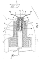
- the projection device or projector P shown in FIGS. 1 to 4 is intended to be supplied with coating material from one or more sources S and displaced, for example with a substantially vertical movement represented by the double arrow F 1 , in O objects look to be coated in an installation I coating these objects.
- the projector P comprises a turbine of which only the central portion 1 is shown which includes a rotor 11 and which is surrounded by a protective cover 2.
- a bowl 3 is intended to be mounted on the rotor 11 and rotated by it, about an axis X-X ', at a speed of several tens of thousands of revolutions per minute, for example 80,000 revolutions / minute. minute, so that the coating product from the source S is sprayed towards an object O, as represented by the arrows F 2 .
- the projector P can be of type electrostatic, that is to say, to include means of electrostatic charge of the front coating product or after it has been unloaded from Ridge 31 of bowl 3.
- the bowl 3 is formed of two parts, namely a hub 32 and a cup portion 33 which defines a surface 34 of flow and distribution of the coating product in the direction of the edge 31.
- the hub 32 is hollow and defines a longitudinal channel 35 which is centered on an axis X 3 -X ' 3 which coincides with the axis XX' when the bowl 3 is mounted on the rotor 1.
- This channel 35 communicates via radial openings 35a with the surface 34.
- the hub 32 constitutes a male part of the bowl 3 which is intended to be introduced into a housing 12 of the rotor 11 centered on the X-X 'axis and extending a channel 15 supply of the bowl 3 in coating product.
- a injection pipette 4 may be provided in channel 15 as shown, in phantom only, in the figure 1.
- the channel 15 communicates with the housing 12 through an area 16 of reduced diameter.
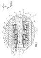
- a cartridge 5 having four annular magnets 51 to parallelepiped section and five magnetic bodies 52 interposed between two magnets 51 adjacent and arranged on both sides of the outside magnets.
- the bodies 52 can be made of any suitable material, for example example steel.
- the magnets 51 all have substantially the same width L 51 taken in a radial direction with respect to the X-X 'axis.
- the magnetic bodies 52 have a width l 52 , measured in the same direction, which increases from the side 53 of the cartridge 5 facing the outside of the rotor 1 towards the duct 15.
- a watertight and nonmagnetic partition 54 is placed in abutment on the edges 52 a of the bodies 52 protruding with respect to the magnets 51 in the direction of the axis X-X ', this partition making it possible to protect, against the mechanical and chemical aggressions, the magnets 51.
- the partition 54 comprises a first portion 54 1 circular cylindrical and centered on the axis XX 'and a second frustoconical portion 54 and divergent 2 towards the side 53 of the cartridge 5, that is to say towards the outlet 12 has the housing 12 outward of the rotor 1.
- the portion 54 2 of the partition 54 is extended by the internal radial surface 55 1 of a shim 55, the half opening angle ⁇ 55 of the frustoconical surface 55 1 being greater than the half-opening angle ⁇ 54 of the surface inside part 54 2 .
- edges 52 have bodies 52 which protrude from the elements 51 are bevelled to match the shape of the outer surface of the partition 54.
- the cartridge 5 defines a volume V 5 receiving the hub 32 of the bowl 3.
- This volume V 5 is delimited by the inner surface of the portion 54 2 which corresponds to a frustoconical geometric surface S 5 and half -angle at the top ⁇ 54 .
- the outer radial surface 32 of the hub 32 is provided with four ribs 36 which are integral with the hub 32, itself made of a magnetic material such as steel. These ribs form radial flanges external to the hub 32 and have, with the exception of the rib 36 closest to the free end 32b of the hub 32, their respective external radial surfaces frustoconical and inscribed in a geometric surface S 3 centered on the longitudinal axis X 3 -X ' 3 , converging towards the free end 32 b of the part 32 and the half-angle at the apex ⁇ 3 .
- the value of the half angle ⁇ 3 is chosen equal to the value of the half angle ⁇ 54 .
- the magnetic coupling force E obtained when the bowl is mounted on the rotor 11 and ready to rotate, has an axial component E 1 , which is non-zero and parallel to the axis xx 'of rotation of the bowl 3 and a component E 2 radial with respect to this axis and also non-zero. This effort is exerted between the elements 52 and 36, through the partition 54.
- the component E 2 has an intensity greater than that of the component E 1 , which is closer to the value of the half angle ⁇ 54 and the relative position of the elements 52 and 36 in the mounted configuration of the bowl 3.
- the thickness e 36 of the ribs 36 taken parallel to the axis X 3 -X ' 3 is substantially equal to the thickness e 52 of the magnetic bodies 52, whereas the spacing d between the ribs 36 is substantially equal to the spacing of two bodies 52, that is to say the thickness e 51 of a magnet 51 taken parallel to the axis X-X '.
- the magnets 51 are identical to each other, whereas the bodies 52 all have the same thickness, their width taken perpendicularly to the axis X-X 'being variable as explained above.
- the ribs or collars circumferential 36 participate in the closing of the field magnetic created by the magnets 51 and that is propagated by magnetic bodies 52.
- FIG. 4 shows a slight offset ⁇ along the axis XX 'between the ribs 36 and the bodies 52. This shift has the effect of exerting on the hub 2 a force F 4 , due to the component E 1 the magnetic force E directed upstream of the duct 15, which has the effect of firmly press the hub 32 inside the cartridge 5 and thus immobilize the bowl 3 relative to the rotor 1.
- the offset ⁇ is progressively increased and the magnetic coupling force gradually decreases, which avoids the sudden movements and the risks for the operator to escape the bowl 3
- the relative values of the components E 1 and E 2 can vary with respect to each other.
- the ribs 36 are produced by surface machining of the surface 32 of the hub 32.
- the ribs or flanges may be formed by rings reported on the hub 32.
- the bowl is without magnets, which makes it particularly attractive on the economic level.
- An O-ring 6 is mounted in the area 16 of reduced diameter and receives the support portion 54 1 of the partition 54, which allows to further isolate the compartment of the cartridge 5 which contains the magnets with respect to the volume of passage of coating and / or cleaning products.
- the partition 54 may not be prolonged up to the level of zone 16, in which case the seal 6 comes resting against the end portion of the hub 32. then provide that zone 16 is slightly conical so to facilitate assembly.
- radial grooves of the gear tooth type, can be machined or reported on the internal radial surface of the cartridge 5 and on the hub 32, this to ensure holding the bowl, and in particular to limit slippage radial and / or tangential of it with respect to magnets, during transient acceleration or deceleration.
- the rotor 111 of this embodiment also forms a feed channel 115. in coating products of a bowl 103 which comprises a hub 132 and a portion 133 provided with a spray edge 131. Magnets 137 are mounted around the hub 132 and are separated in pairs by a magnetic body 136 constituted by ribs or rings attached to the hub 132.
- a cartridge 105 is mounted in a housing 112 formed at the outlet of the channel 115 and comprises a magnetic ring provided with internal ribs or flanges 152 whose thickness and spacing, taken parallel to the direction of the axis XX 'of rotation of the rotor 101, are respectively equal to the thickness and spacing of the bodies 136, taken parallel to the central axis X 103 -X ' 103 of the bowl 103.
- This embodiment corresponds in practice to first embodiment to which a structure reversal between the part carrying the magnets, here the bowl 103, and the part equipped with ribs constituting the induced poles of magnetic coupling, here the rotor 111.
- the volume V 105 for receiving the hub 132 in the housing 112 is divergent towards the outlet 112 of the housing and the geometry of the surfaces defining this volume and the outer casing of the hub, respectively, is chosen to allow a support surface of the hub in the cartridge.
- the rotor 211 of this embodiment also forms a feed channel 215.
- coating material of a bowl 203 which comprises a hub 232 and a portion 233 provided with a spraying edge 231.
- the rotor 211 is equipped with a hollow central shaft 217 on which are mounted magnets 251 separated by bodies 252 and at the center of which extends the channel 215 in the form of a channel 217 b of reduced diameter. This channel 217 b supplies the bowl 203 with coating and / or cleaning products.
- the hub 232 forms a housing 212 for receiving the shaft 217 when the bowl 203 is mounted on the rotor 211.
- the inner surface of the hub 232 is provided with ribs 236 which extend towards the axis X 203 -X ' 203 and are intended to be approximately aligned with the bodies 252 to form the poles induced by the elements 251 and 252 when a magnetic coupling is obtained between the elements 211 and 203.
- the coupling effort magnet obtained has a radial component with respect to the X-X 'axis.
- a sealed and non-magnetic partition 238 may be mounted in abutment on the ribs 236 and the inner surface S 6 is divergent towards the outlet 212 of the housing 212, while the outer surface of the magnets 251 and body 252 is convergent in the direction of the free end 217 of the shaft 217, which facilitates the mechanical centering of the elements 203 and 207 relative to each other.
- the thickness of the ribs 236 is chosen substantially equal to the thickness of the bodies 252 taken parallel to the X-X 'axis, their spacings relative values are also substantially equal.
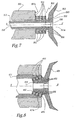
- the rotor 311 of this embodiment also forms a supply channel 315.
- a bowl 303 which includes a hub 332 to be inserted in a recess 360 defined at the center of an annular cartridge 305 attached to the front face 301 has a housing 301 wherein the rotor 311 can rotate about its axis central X-X '.
- the cartridge 305 comprises three magnets 351 as well as four ferro-magnetic bodies 352 in the form of washers, these bodies 352 being intended to be approximately aligned with external radial ribs 336 formed on the outer radial surface of the means 332.
- the magnets 351 and the washers 352 are circular and centered on the X-X 'axis. North and South polarities magnets 351 are opposed two by two, as in the modes previous embodiments.
- Ribs 336 could also be reported on the hub 332.
- the hub 332 is hollow and provided with an internal radial surface 338 which is tapered and against which abuts the front end truncated cone 311 has the rotor 311, which allows engagement of the bowl 303 on the rotor 311, like a Morse taper.
- the elements 336 and 352 are not perfectly aligned in the mounted configuration of the bowl, such 7, so that the magnetic coupling force generated also has a left-handed component in FIG. 7, which tends to firmly press the bowl 303 onto the rotor 311.
- the magnets 451 and the magnetic bodies 452 are arranged with a frustoconical configuration, the bowl 403 having, meanwhile, a hub 432 whose outer surface is frustoconical and converging towards the rear of the rotor 411, this surface being equipped with ribs 436 intended to be, at least approximately, in alignment with the bodies 452.
- An advantage of this embodiment is that it makes it possible to obtain an intensity-calibrated fastening force by eliminating a possible "magnetic detent" effect which may be displeasing to the operator.
- the conicity of the magnets 451 is chosen sufficient so that the successive air gaps are greater than the attraction distance, up to the mounted position of the bowl 403, the quality of the magnets and the precision of the assembly to define this taper.
- This embodiment also has the advantage of good compactness in the direction of the axis XX 'and a possibility of pre-positioning of the bowl 403 in the front end 411 of the rotor 411 during its assembly.
- the relative spacing of the ribs 36 and equivalent may be chosen equal to a submultiple of the width 51 of the magnets 51, that is to say the relative spacing magnetic bodies 52 and the like. Indeed, an alignment of certain ribs 36 or equivalent with the bodies 52 and the like remain possible, some other ribs then being opposite the magnets 51. These other ribs are then not very functional for the desired magnetic coupling. This is applicable to all the embodiments envisaged.
- the spacing d may be equal to a multiple of the spacing of the body 52.
- some of the bodies 52 are opposite an intermediate region between two ribs 36 or equivalent. This can also be applied to all contemplated embodiments.
- the invention has been represented with bowls 3, 103 or 203 bipartite. It is also applicable with a bowl whose product distribution part and hub are monoblock.
- the representation of bowls 303 and 403 is very schematic.
- the invention is applicable regardless of the nature exact product, projected, liquid or powdery, water soluble or not.
- the invention operates with electrostatic projectors or not. Characteristics techniques of the described embodiments may be combined within the framework of this invention.
- the invention is applicable regardless of the number the exact magnet (s) and rib (s) used, the number of ribs (s) being, in practice, adapted to the number Magnet (s).
Landscapes
- Nozzles (AREA)
- Catching Or Destruction (AREA)
- Reciprocating Pumps (AREA)
- Containers And Packaging Bodies Having A Special Means To Remove Contents (AREA)
- Structures Of Non-Positive Displacement Pumps (AREA)
- Medicinal Preparation (AREA)
- Electrostatic Spraying Apparatus (AREA)
Description
- la figure 1 est une coupe longitudinale de principe d'un projecteur de produit de revêtement conforme à un premier mode de réalisation de l'invention, incorporant un bol conforme à un premier mode de réalisation et faisant partie d'une installation conforme à l'invention ;
- la figure 2 est une coupe longitudinale du rotor et une vue de côté du bol du dispositif de la figure 1 ;
- la figure 3 est une vue en perspective avec arrachement partiel des éléments représentés à la figure 2 ;
- la figure 4 est une vue à plus grande échelle du détail IV à la figure 1 ;
- la figure 4A est une représentation vectorielle de l'effort de couplage magnétique dans la configuration de la figure 4 ;
- la figure 5 est une vue analogue à la figuré 2 pour un dispositif de projection et un bol conformes à un deuxième mode de réalisation de l'invention ;
- la figure 6 est une vue analogue à la figure 2 pour un dispositif de projection et un bol conformes à un troisième mode de réalisation de l'invention ;
- la figure 7 est une coupe longitudinale de principe d'un dispositif conforme à un quatrième mode de réalisation de l'invention et
- la figure 8 est une coupe analogue à la figure 7 pour un cinquième mode de réalisation de l'invention.
- une bonne compacité axiale qui est importante car il convient de réduire le plus possible la dimension axiale d'un pulvérisateur pour atteindre correctement des zones d'un objet à revêtir dont le rayon de courbure faible, telles que les détourages de portes de carrosserie de véhicule automobile. Ceci permet d'améliorer la manoeuvrabilité d'un robot et d'un pulvérisateur incorporant l'invention et de réduire le moment résistant sur le poignet.
- des pertes de peinture minimisées du fait de la compacité axiale obtenue pour le projecteur. Ceci induit également une consommation moindre de produits de rinçage lors des changements des produits de revêtement.
- une protection améliorée des aimants contre les chocs, ces aimants étant fragiles par construction.
Claims (22)
- Bol de pulvérisation pour projecteur rotatif de produit de revêtement, ledit bol étant équipé de moyens de couplage magnétique avec un organe d'entraínement en rotation ou avec un boítier entourant ledit organe, caractérisé en ce que lesdits moyens de couplage magnétique (36 ; 136 ; 236 ; 336 ; 436) sont aptes à coopérer avec des moyens complémentaires portés par ledit organe (11 ; 111 ; 211 ; 411) ou ledit boítier (301) de telle manière que l'effort de couplage magnétique (E) à une composante (E2) radiale par rapport à l'axe de rotation (X-X') dudit bol (3 ; 103 ; 203 ; 303 ; 403).
- Bol selon la revendication 1, caractérisé en ce que lesdits moyens de couplage magnétique comprennent au moins un élément magnétique (36 ; 136 ; 236 ; 336 ; 436) qui est soit disposé autour d'une partie mâle (32 ; 132 ; 332 ; 432) dudit bol (3 ; 103 ; 303 ; 403) apte à être engagée dans un logement central (12 ; 112 ; 360) dudit organe (11 ; 111 ; 411) ou dudit boítier (301) soit disposé à l'intérieur d'une partie femelle (232) dudit bol (203) formant un logement (212) de réception d'un arbre central (217) solidaire dudit organe (211).
- Bol selon la revendication 2, caractérisé en ce que lesdits éléments magnétiques forment des collerettes radiales (36 ; 136 ; 236 ; 336 ; 436) qui s'étendent soit vers l'extérieur à partir de ladite partie mâle (32 ; 132 ; 332 ; 432), soit vers l'axe géométrique (X-X') de rotation dudit bol à partir de ladite partie femelle (232).
- Bol (103) selon l'une des revendications 2 ou 3, caractérisé en ce que des aimants permanents (137) sont disposés entre chaque paire d'éléments magnétiques adjacents (136).
- Bol (3 ; 203 ; 303 ; 403) selon l'une des revendications 2 ou 3, caractérisé en ce qu'il est dépourvu d'aimants.
- Bol selon l'une des revendications 2 à 5, caractérisé en ce que lesdits éléments magnétiques (36 ; 136 ; 236 ; 436) sont inscrits dans une surface d'enveloppe (S3) convergente en direction de l'extrémité libre (32b) de ladite partie mâle (32 ; 432) ou divergente en direction du débouché (212a) du logement (212) de ladite partie femelle (232).
- Bol selon l'une des revendications 2 à 6, caractérisé en ce que ladite partie mâle (32 ; 132 ; 332 ; 432) est creuse et forme un canal (35) d'alimentation en produit de revêtement pour une surface (34) et/ou une arête de pulvérisation (31) dudit bol (3 ; 103).
- Bol selon l'une des revendications précédentes, caractérisé en ce qu'il est pourvu de moyens (338) d'emboítement sur ledit organe (311) lesdits moyens de couplage magnétique (336) étant disposés autour desdits moyens d'emboítement et aptes à coopérer avec des moyens complémentaires (352) non entraínés en rotation par ledit organe, pour contribuer à un effort d'emboítement dudit bol sur ledit organe.
- Dispositif de projection de produit de revêtement comprenant un bol et un organe apte à entraíner ledit bol en rotation, des moyens de couplage magnétique, entre ledit bol et ledit organe ou entre ledit bol et un boítier entourant ledit organe, étant prévus et incluant au moins un aimant permanent, caractérisé en ce que lesdits moyens de couplage (36, 52 ; 136, 152 ; 236, 252 ; 336, 352 ; 436, 452) sont disposés de telle manière que l'effort de couplage magnétique (E) a une composante (E2) radiale par rapport à l'axe de rotation (X-X') dudit bol (3 ; 103 ; 203 ; 303 ; 403).
- Dispositif selon la revendication 9, caractérisé en ce que lesdits moyens de couplage magnétique comprennent en outre au moins un corps magnétique (52 ; 136 ; 252 ; 352 ; 452) associé audit aimant (51 ; 137 ; 251 ; 351 ; 451), et monté sur l'un (11 ; 103 ; 211 ; 301 ; 411) des deux éléments que sont ledit bol (3 ; 103 ; 203 ; 403) et ledit organe (11 ; 111 ; 211 ; 411) ou ledit bol (303) et ledit boítier (301), alors que l'autre élément (3 ; 111 ; 203 ; 303 ; 403) porte au moins une nervure (36 ; 152 ; 236 ; 336 ; 436) formée dans un matériau magnétique.
- Dispositif selon la revendication 10, caractérisé en ce que l'épaisseur (e 36) de ladite ou desdites nervures (36 ; 152 ; 236 ; 336 ; 436) est sensiblement égale à l'épaisseur (e 52) dudit ou desdits corps (52 ; 136 ; 252 ; 352 ; 452).
- Dispositif selon l'une des revendications 10 ou 11, caractérisé en ce qu'il comprend plusieurs corps magnétiques et plusieurs nervures et en ce que l'écartement relatif (d) desdites nervures (36 ; 152 ; 236 ; 336 ; 436) est sensiblement égal à, ou correspond sensiblement à un multiple ou un sous-multiple, de l'écartement relatif (d') desdits corps (52 ; 136 ; 252 ; 352 ; 452).
- Dispositif selon l'une des revendications 10 à 13, caractérisé en ce que ledit bol (3 ; 103) est pourvu d'une partie mâle (32 ; 132 ; 432) autour de laquelle est ou sont disposés lesdites nervures (36 ; 436) ou lesdits corps (136), alors que ledit organe d'entraínement est pourvu d'un logement central (12 ; 112) de réception de ladite partie mâle, des éléments (51, 52 ; 152 ; 452) de couplage magnétique complémentaires de ceux portés par ledit bol étant prévus dans ledit logement, autour de ladite partie mâle.
- Dispositif selon la revendication 13, caractérisé en ce que ledit ou lesdits aimants (51) et les corps magnétiques associés (52) sont regroupés sous la forme d'une cartouche (5) disposée dans ledit logement (12), alors que lesdites nervures (36) sont prévues autour de ladite partie mâle (32).
- Dispositif selon l'une des revendications 13 ou 14, caractérisé en ce que le volume (V5 ; V105) de réception (12 ; 112) de ladite partie mâle (32 ; 132 ; 432) dans ledit logement (12 ; 112) est délimité par une surface de révolution (S5) centrée sur l'axe de rotation (X-X') dudit organe d'entraínement (11 ; 111 ; 411) et divergente en direction du débouché (12a ; 112a) dudit logement, alors que lesdites nervures (36 ; 436) ou lesdits corps (136) portés par ladite partie mâle sont inscrits dans une surface d'enveloppe (S3) qui a sensiblement la même géométrie que celle (S5) définissant ledit volume et qui est convergente en direction de l'extrémité libre (32b) de ladite partie mâle.
- Dispositif selon l'une des revendications 10 à 12, caractérisé en ce que ledit bol (203) est pourvu d'une partie femelle (232) à l'intérieur de laquelle est ou sont ménagées lesdites nervures (236), alors que ledit organe d'entraínement est pourvu d'un arbre central (217) apte à être engagé dans un logement (212) formé dans ladite partie femelle, des éléments (252) de couplage magnétique complémentaires de ceux (236) portés par ledit bol étant montés sur ledit arbre.
- Dispositif selon la revendication 16, caractérisé en ce que le logement (212) ménagé dans ladite partie femelle pour la réception dudit arbre (217) est délimité par une surface de révolution centrée sur un axe central dudit bol (X203-X203,) et divergente en direction du débouché (212a) dudit logement, alors que lesdits corps (252) ou lesdites nervures portés par ledit arbre (217) sont inscrits dans une surface d'enveloppe qui a sensiblement la même géométrie que celle définissant ledit logement et qui est convergente en direction de l'extrémité libre (217a) dudit arbre.
- Dispositif selon l'une des revendications 9 à 12, caractérisé en ce que ledit bol est pourvu d'une partie mâle (332) apte à être insérée dans un logement (360) défini par un boítier (301) entourant ledit organe d'entraínement (311), ladite partie mâle étant elle-même équipée de moyens (338) d'emboítement sur ledit organe.
- Dispositif selon la revendication 18, caractérisé en ce que lesdits moyens d'emboítement comprennent une portée tronconique (338) de forme globalement complémentaire de celle de l'extrémité (311a) dudit organe (311).
- Dispositif selon l'une des revendications 9 à 19, caractérisé en ce que ledit organe d'entraínement (1 ; 111 ; 211 ; 311 ; 411) est pourvu d'un canal central (15 ; 115 ; 215, 217b) d'alimentation en produit de revêtement, alors que ledit bol (3 ; 103 ; 203 ; 303 ; 403) est pourvu d'un canal central (35) d'alimentation en produit de revêtement pour une surface (34) et/ou une arête (31 ; 231) de décharge, lesdits canaux étant raccordés l'un à l'autre lorsque ledit bol est couplé magnétiquement audit organe ou audit boítier (301), le couplage magnétique ayant lieu autour de l'un desdits canaux (35 ; 217b).
- Dispositif selon l'une des revendications 9 à 20, caractérisé en ce qu'il est prévu, sur ledit bol (3 ; 103 ; 203 ; 303 ; 403) et sur ledit organe (11 ; 111 ; 211 ; 311 ; 411), des reliefs d'engrènement.
- Installation (I) de projection de produit de revêtement, caractérisée en ce qu'elle comprend au moins un dispositif de projection (P) selon l'une des revendications 9 à 21.
Applications Claiming Priority (5)
| Application Number | Priority Date | Filing Date | Title |
|---|---|---|---|
| US41028102P | 2002-09-13 | 2002-09-13 | |
| US410281P | 2002-09-13 | ||
| FR0303783 | 2003-03-27 | ||
| FR0303783A FR2852868B1 (fr) | 2003-03-27 | 2003-03-27 | Bol de pulverisation, dispositif de projection incorporant un tel bol et installation de projection incorporant un tel dispositif |
| PCT/FR2003/002706 WO2004024338A2 (fr) | 2002-09-13 | 2003-09-12 | Bol de pulverisation, dispositif de projection incorporant un tel bol et installation de projection incorporant un tel dispositif |
Publications (2)
| Publication Number | Publication Date |
|---|---|
| EP1545792A2 EP1545792A2 (fr) | 2005-06-29 |
| EP1545792B1 true EP1545792B1 (fr) | 2005-12-28 |
Family
ID=31995634
Family Applications (1)
| Application Number | Title | Priority Date | Filing Date |
|---|---|---|---|
| EP03795046A Expired - Lifetime EP1545792B1 (fr) | 2002-09-13 | 2003-09-12 | Bol de pulverisation, dispositif de projection incorporant un tel bol et installation de projection incorporant un tel dispositif |
Country Status (6)
| Country | Link |
|---|---|
| US (1) | US7041173B2 (fr) |
| EP (1) | EP1545792B1 (fr) |
| AT (1) | ATE314151T1 (fr) |
| AU (1) | AU2003276336A1 (fr) |
| DE (1) | DE60303049T2 (fr) |
| WO (1) | WO2004024338A2 (fr) |
Families Citing this family (9)
| Publication number | Priority date | Publication date | Assignee | Title |
|---|---|---|---|---|
| FR2868342B1 (fr) * | 2004-04-02 | 2006-06-02 | Sames Technologies Soc Par Act | Bol de pulverisation, projecteur rotatif incorporant un tel bol et installation de projection incorporant un tel projecteur |
| DE602005005635T2 (de) | 2004-02-06 | 2009-05-14 | Sames Technologies | Sprühglocke für einen rotationszerstäuber mit magnetischer befestigung |
| DE102004032045A1 (de) * | 2004-07-02 | 2006-01-26 | J. Wagner Ag | Rotationszerstäuber |
| US7416607B2 (en) * | 2005-05-25 | 2008-08-26 | Taiwan Semiconductor Manufacturing Co., Ltd. | Fluid injection apparatus for semiconductor processing |
| AT506722B1 (de) * | 2008-04-21 | 2011-01-15 | Kronsteiner Martin Ing | Ausbringgerät |
| US10343178B2 (en) * | 2014-01-29 | 2019-07-09 | Honda Motor Co., Ltd. | Rotary atomizing coating device and spray head |
| FR3048896B1 (fr) * | 2016-03-21 | 2018-04-13 | Exel Industries | Pulverisateur de produit de revetement, procede de montage et de demontage |
| DE102019135592A1 (de) * | 2019-12-20 | 2021-06-24 | Eisenmann Se | Rotationszerstäuber zur Abgabe eines Beschichtungsmittels und Glockenteller hierfür |
| GB2598957B (en) | 2020-09-22 | 2023-07-05 | Novanta Tech Uk Limited | Rotary atomisers |
Family Cites Families (5)
| Publication number | Priority date | Publication date | Assignee | Title |
|---|---|---|---|---|
| US4023057A (en) * | 1974-03-22 | 1977-05-10 | Pacific Textile & Chemical Corporation | Electric motor field magnets |
| FR2497439B1 (fr) | 1981-01-06 | 1985-06-07 | Tecnoma | Installation pour la pulverisation d'un liquide de traitement, notamment de traitement des cultures ou des sols |
| FR2698564B1 (fr) | 1992-12-01 | 1995-03-03 | Sames Sa | Dispositif de projection de produit de revêtement à élément rotatif de pulvérisation et outil pour le montage et le démontage d'un tel élément rotatif. |
| FR2805182B1 (fr) | 2000-02-21 | 2002-09-20 | Sames Sa | Dispositif de projection de produit de revetement comprenant un element rotatif de pulverisation |
| DE10010734A1 (de) | 2000-03-04 | 2001-09-06 | Continental Teves Ag & Co Ohg | Elektromagnetventil, insbesondere für schlupfgeregelte Kraftfahrzeugbremsanlagen |
-
2003
- 2003-09-12 EP EP03795046A patent/EP1545792B1/fr not_active Expired - Lifetime
- 2003-09-12 AT AT03795046T patent/ATE314151T1/de not_active IP Right Cessation
- 2003-09-12 WO PCT/FR2003/002706 patent/WO2004024338A2/fr not_active Ceased
- 2003-09-12 DE DE60303049T patent/DE60303049T2/de not_active Expired - Lifetime
- 2003-09-12 AU AU2003276336A patent/AU2003276336A1/en not_active Abandoned
- 2003-09-15 US US10/661,776 patent/US7041173B2/en not_active Expired - Lifetime
Also Published As
| Publication number | Publication date |
|---|---|
| WO2004024338A2 (fr) | 2004-03-25 |
| US20040140378A1 (en) | 2004-07-22 |
| EP1545792A2 (fr) | 2005-06-29 |
| WO2004024338A3 (fr) | 2004-04-22 |
| ATE314151T1 (de) | 2006-01-15 |
| DE60303049D1 (de) | 2006-02-02 |
| DE60303049T2 (de) | 2006-08-31 |
| AU2003276336A1 (en) | 2004-04-30 |
| US7041173B2 (en) | 2006-05-09 |
Similar Documents
| Publication | Publication Date | Title |
|---|---|---|
| EP1257365B1 (fr) | Dispositif de projection de produit de revetement et element rotatif de pulverisation pour un tel dispositif | |
| EP2139604B1 (fr) | Organe de pulverisation, dispositif de projection comportant un tel organe, installation de projection et methode de nettoyage d'un tel organe | |
| FR3069300B1 (fr) | Ensemble comportant un rouet de lubrification et des gicleurs de lubrifiant, pour un reducteur de vitesse a train epicycloidal de turbomachine | |
| EP3277932B1 (fr) | Ensemble rotor et turbomachine à paliers à gaz comportant un tel ensemble rotor | |
| EP1545792B1 (fr) | Bol de pulverisation, dispositif de projection incorporant un tel bol et installation de projection incorporant un tel dispositif | |
| CA2544784A1 (fr) | Module de turbine pour moteur a turbine a gaz | |
| EP1711269B1 (fr) | Bol de pulverisation pour un projecteur rotatif avec fixation magnetique | |
| EP2370864A1 (fr) | Piece d'horlogerie comprenant un organe de pivotement | |
| EP3873677B1 (fr) | Bol de pulvérisation de produit de revêtement, projecteur rotatif incluant un tel bol et procédé de nettoyage d'un tel projecteur | |
| FR3114364A1 (fr) | Cage de roulement et roulement | |
| FR2852868A1 (fr) | Bol de pulverisation, dispositif de projection incorporant un tel bol et installation de projection incorporant un tel dispositif | |
| EP3807508B1 (fr) | Porte-satellites tournant pour un reducteur mecanique d'une turbomachine | |
| EP4034755B1 (fr) | Dispositif de refroidissement par jets d'air d'un carter de turbine | |
| EP3807507B1 (fr) | Dispositif de repartition d'huile pour un porte-satellites tournant d'un reducteur mecanique d'une turbomachine | |
| EP4163517A1 (fr) | Système de transmission comportant un dispositif de réduction et un dispositif d'entraînement différentiel | |
| EP3647626B1 (fr) | Roue dentee | |
| FR2702983A1 (fr) | Turbine de grenaillage. | |
| FR3047122A1 (fr) | Ensemble de support d'un moteur electrique, notamment dans un dispositif de chauffage, ventilation et/ou climatisation pour vehicule automobile | |
| FR2887472A1 (fr) | Bol de pulverisation, dispositif de projection equipe d'un tel bol, installation comprenant un tel dispositif et procede de montage d'un tel bol | |
| EP4512532A1 (fr) | Organe de pulvérisation et projecteur rotatif de produit de revêtement comprenant un tel organe de pulvérisation | |
| EP4656296A1 (fr) | Bol de pulvérisation de produit de revêtement liquide, pulvérisateur rotatif comprenant un tel bol et procédé d application de produit de revêtement avec un tel pulvérisateur | |
| FR3149062A1 (fr) | Système de transmission équipé d’un dispositif d’accouplement | |
| FR2973452A1 (fr) | Pompe a engrenage interne | |
| EP4317664A1 (fr) | Gouttière de récupération d'huile pour un réducteur de turbomachine | |
| FR3047123A1 (fr) | Ensemble de support d'un moteur electrique, notamment dans un dispositif de chauffage, ventilation et/ou climatisation pour vehicule automobile |
Legal Events
| Date | Code | Title | Description |
|---|---|---|---|
| PUAI | Public reference made under article 153(3) epc to a published international application that has entered the european phase |
Free format text: ORIGINAL CODE: 0009012 |
|
| GRAP | Despatch of communication of intention to grant a patent |
Free format text: ORIGINAL CODE: EPIDOSNIGR1 |
|
| 17P | Request for examination filed |
Effective date: 20050217 |
|
| AK | Designated contracting states |
Kind code of ref document: A2 Designated state(s): AT BE BG CH CY CZ DE DK EE ES FI FR GB GR HU IE IT LI LU MC NL PT RO SE SI SK TR |
|
| AX | Request for extension of the european patent |
Extension state: AL LT LV MK |
|
| GRAS | Grant fee paid |
Free format text: ORIGINAL CODE: EPIDOSNIGR3 |
|
| GRAA | (expected) grant |
Free format text: ORIGINAL CODE: 0009210 |
|
| AK | Designated contracting states |
Kind code of ref document: B1 Designated state(s): AT BE BG CH CY CZ DE DK EE ES FI FR GB GR HU IE IT LI LU MC NL PT RO SE SI SK TR |
|
| DAX | Request for extension of the european patent (deleted) | ||
| PG25 | Lapsed in a contracting state [announced via postgrant information from national office to epo] |
Ref country code: IT Free format text: LAPSE BECAUSE OF FAILURE TO SUBMIT A TRANSLATION OF THE DESCRIPTION OR TO PAY THE FEE WITHIN THE PRESCRIBED TIME-LIMIT;WARNING: LAPSES OF ITALIAN PATENTS WITH EFFECTIVE DATE BEFORE 2007 MAY HAVE OCCURRED AT ANY TIME BEFORE 2007. THE CORRECT EFFECTIVE DATE MAY BE DIFFERENT FROM THE ONE RECORDED. Effective date: 20051228 Ref country code: FI Free format text: LAPSE BECAUSE OF FAILURE TO SUBMIT A TRANSLATION OF THE DESCRIPTION OR TO PAY THE FEE WITHIN THE PRESCRIBED TIME-LIMIT Effective date: 20051228 Ref country code: SK Free format text: LAPSE BECAUSE OF FAILURE TO SUBMIT A TRANSLATION OF THE DESCRIPTION OR TO PAY THE FEE WITHIN THE PRESCRIBED TIME-LIMIT Effective date: 20051228 Ref country code: SI Free format text: LAPSE BECAUSE OF FAILURE TO SUBMIT A TRANSLATION OF THE DESCRIPTION OR TO PAY THE FEE WITHIN THE PRESCRIBED TIME-LIMIT Effective date: 20051228 Ref country code: RO Free format text: LAPSE BECAUSE OF FAILURE TO SUBMIT A TRANSLATION OF THE DESCRIPTION OR TO PAY THE FEE WITHIN THE PRESCRIBED TIME-LIMIT Effective date: 20051228 Ref country code: AT Free format text: LAPSE BECAUSE OF FAILURE TO SUBMIT A TRANSLATION OF THE DESCRIPTION OR TO PAY THE FEE WITHIN THE PRESCRIBED TIME-LIMIT Effective date: 20051228 Ref country code: CZ Free format text: LAPSE BECAUSE OF FAILURE TO SUBMIT A TRANSLATION OF THE DESCRIPTION OR TO PAY THE FEE WITHIN THE PRESCRIBED TIME-LIMIT Effective date: 20051228 Ref country code: IE Free format text: LAPSE BECAUSE OF FAILURE TO SUBMIT A TRANSLATION OF THE DESCRIPTION OR TO PAY THE FEE WITHIN THE PRESCRIBED TIME-LIMIT Effective date: 20051228 Ref country code: GB Free format text: LAPSE BECAUSE OF FAILURE TO SUBMIT A TRANSLATION OF THE DESCRIPTION OR TO PAY THE FEE WITHIN THE PRESCRIBED TIME-LIMIT Effective date: 20051228 Ref country code: NL Free format text: LAPSE BECAUSE OF FAILURE TO SUBMIT A TRANSLATION OF THE DESCRIPTION OR TO PAY THE FEE WITHIN THE PRESCRIBED TIME-LIMIT Effective date: 20051228 |
|
| REG | Reference to a national code |
Ref country code: GB Ref legal event code: FG4D Free format text: NOT ENGLISH |
|
| REG | Reference to a national code |
Ref country code: CH Ref legal event code: EP |
|
| REG | Reference to a national code |
Ref country code: IE Ref legal event code: FG4D Free format text: LANGUAGE OF EP DOCUMENT: FRENCH |
|
| REF | Corresponds to: |
Ref document number: 60303049 Country of ref document: DE Date of ref document: 20060202 Kind code of ref document: P |
|
| PG25 | Lapsed in a contracting state [announced via postgrant information from national office to epo] |
Ref country code: GR Free format text: LAPSE BECAUSE OF FAILURE TO SUBMIT A TRANSLATION OF THE DESCRIPTION OR TO PAY THE FEE WITHIN THE PRESCRIBED TIME-LIMIT Effective date: 20060328 Ref country code: SE Free format text: LAPSE BECAUSE OF FAILURE TO SUBMIT A TRANSLATION OF THE DESCRIPTION OR TO PAY THE FEE WITHIN THE PRESCRIBED TIME-LIMIT Effective date: 20060328 Ref country code: DK Free format text: LAPSE BECAUSE OF FAILURE TO SUBMIT A TRANSLATION OF THE DESCRIPTION OR TO PAY THE FEE WITHIN THE PRESCRIBED TIME-LIMIT Effective date: 20060328 Ref country code: BG Free format text: LAPSE BECAUSE OF FAILURE TO SUBMIT A TRANSLATION OF THE DESCRIPTION OR TO PAY THE FEE WITHIN THE PRESCRIBED TIME-LIMIT Effective date: 20060328 |
|
| PG25 | Lapsed in a contracting state [announced via postgrant information from national office to epo] |
Ref country code: ES Free format text: LAPSE BECAUSE OF FAILURE TO SUBMIT A TRANSLATION OF THE DESCRIPTION OR TO PAY THE FEE WITHIN THE PRESCRIBED TIME-LIMIT Effective date: 20060408 |
|
| PG25 | Lapsed in a contracting state [announced via postgrant information from national office to epo] |
Ref country code: PT Free format text: LAPSE BECAUSE OF FAILURE TO SUBMIT A TRANSLATION OF THE DESCRIPTION OR TO PAY THE FEE WITHIN THE PRESCRIBED TIME-LIMIT Effective date: 20060529 |
|
| NLV1 | Nl: lapsed or annulled due to failure to fulfill the requirements of art. 29p and 29m of the patents act | ||
| PG25 | Lapsed in a contracting state [announced via postgrant information from national office to epo] |
Ref country code: HU Free format text: LAPSE BECAUSE OF FAILURE TO SUBMIT A TRANSLATION OF THE DESCRIPTION OR TO PAY THE FEE WITHIN THE PRESCRIBED TIME-LIMIT Effective date: 20060629 |
|
| GBV | Gb: ep patent (uk) treated as always having been void in accordance with gb section 77(7)/1977 [no translation filed] |
Effective date: 20051228 |
|
| REG | Reference to a national code |
Ref country code: IE Ref legal event code: FD4D |
|
| PG25 | Lapsed in a contracting state [announced via postgrant information from national office to epo] |
Ref country code: MC Free format text: LAPSE BECAUSE OF NON-PAYMENT OF DUE FEES Effective date: 20060930 Ref country code: BE Free format text: LAPSE BECAUSE OF NON-PAYMENT OF DUE FEES Effective date: 20060930 |
|
| PLBE | No opposition filed within time limit |
Free format text: ORIGINAL CODE: 0009261 |
|
| STAA | Information on the status of an ep patent application or granted ep patent |
Free format text: STATUS: NO OPPOSITION FILED WITHIN TIME LIMIT |
|
| 26N | No opposition filed |
Effective date: 20060929 |
|
| BERE | Be: lapsed |
Owner name: SAMES TECHNOLOGIES Effective date: 20060930 |
|
| REG | Reference to a national code |
Ref country code: CH Ref legal event code: PL |
|
| PG25 | Lapsed in a contracting state [announced via postgrant information from national office to epo] |
Ref country code: EE Free format text: LAPSE BECAUSE OF FAILURE TO SUBMIT A TRANSLATION OF THE DESCRIPTION OR TO PAY THE FEE WITHIN THE PRESCRIBED TIME-LIMIT Effective date: 20051228 |
|
| PG25 | Lapsed in a contracting state [announced via postgrant information from national office to epo] |
Ref country code: CH Free format text: LAPSE BECAUSE OF NON-PAYMENT OF DUE FEES Effective date: 20070930 Ref country code: LI Free format text: LAPSE BECAUSE OF NON-PAYMENT OF DUE FEES Effective date: 20070930 Ref country code: LU Free format text: LAPSE BECAUSE OF NON-PAYMENT OF DUE FEES Effective date: 20060912 Ref country code: TR Free format text: LAPSE BECAUSE OF FAILURE TO SUBMIT A TRANSLATION OF THE DESCRIPTION OR TO PAY THE FEE WITHIN THE PRESCRIBED TIME-LIMIT Effective date: 20051228 |
|
| PG25 | Lapsed in a contracting state [announced via postgrant information from national office to epo] |
Ref country code: CY Free format text: LAPSE BECAUSE OF FAILURE TO SUBMIT A TRANSLATION OF THE DESCRIPTION OR TO PAY THE FEE WITHIN THE PRESCRIBED TIME-LIMIT Effective date: 20051228 |
|
| REG | Reference to a national code |
Ref country code: FR Ref legal event code: PLFP Year of fee payment: 14 |
|
| REG | Reference to a national code |
Ref country code: DE Ref legal event code: R082 Ref document number: 60303049 Country of ref document: DE Representative=s name: PFENNING, MEINIG & PARTNER MBB PATENTANWAELTE, DE Ref country code: DE Ref legal event code: R081 Ref document number: 60303049 Country of ref document: DE Owner name: SAMES KREMLIN, FR Free format text: FORMER OWNER: SAMES TECHNOLOGIES, MEYLAN, FR |
|
| REG | Reference to a national code |
Ref country code: FR Ref legal event code: PLFP Year of fee payment: 15 |
|
| REG | Reference to a national code |
Ref country code: FR Ref legal event code: TP Owner name: SAMES KREMLIN, FR Effective date: 20171010 |
|
| REG | Reference to a national code |
Ref country code: FR Ref legal event code: PLFP Year of fee payment: 16 |
|
| PGFP | Annual fee paid to national office [announced via postgrant information from national office to epo] |
Ref country code: DE Payment date: 20220916 Year of fee payment: 20 |
|
| PGFP | Annual fee paid to national office [announced via postgrant information from national office to epo] |
Ref country code: FR Payment date: 20220922 Year of fee payment: 20 |
|
| REG | Reference to a national code |
Ref country code: DE Ref legal event code: R071 Ref document number: 60303049 Country of ref document: DE |