EP1545792B1 - Spray bowl, discharge device comprising one such bowl and discharge installation comprising one such device - Google Patents
Spray bowl, discharge device comprising one such bowl and discharge installation comprising one such device Download PDFInfo
- Publication number
- EP1545792B1 EP1545792B1 EP03795046A EP03795046A EP1545792B1 EP 1545792 B1 EP1545792 B1 EP 1545792B1 EP 03795046 A EP03795046 A EP 03795046A EP 03795046 A EP03795046 A EP 03795046A EP 1545792 B1 EP1545792 B1 EP 1545792B1
- Authority
- EP
- European Patent Office
- Prior art keywords
- bowl
- magnetic
- housing
- male part
- ribs
- Prior art date
- Legal status (The legal status is an assumption and is not a legal conclusion. Google has not performed a legal analysis and makes no representation as to the accuracy of the status listed.)
- Expired - Lifetime
Links
Images


Classifications
-
- B—PERFORMING OPERATIONS; TRANSPORTING
- B05—SPRAYING OR ATOMISING IN GENERAL; APPLYING FLUENT MATERIALS TO SURFACES, IN GENERAL
- B05B—SPRAYING APPARATUS; ATOMISING APPARATUS; NOZZLES
- B05B3/00—Spraying or sprinkling apparatus with moving outlet elements or moving deflecting elements
- B05B3/02—Spraying or sprinkling apparatus with moving outlet elements or moving deflecting elements with rotating elements
- B05B3/10—Spraying or sprinkling apparatus with moving outlet elements or moving deflecting elements with rotating elements discharging over substantially the whole periphery of the rotating member, i.e. the spraying being effected by centrifugal forces
- B05B3/1035—Driving means; Parts thereof, e.g. turbine, shaft, bearings
- B05B3/1042—Means for connecting, e.g. reversibly, the rotating spray member to its driving shaft
-
- B—PERFORMING OPERATIONS; TRANSPORTING
- B05—SPRAYING OR ATOMISING IN GENERAL; APPLYING FLUENT MATERIALS TO SURFACES, IN GENERAL
- B05B—SPRAYING APPARATUS; ATOMISING APPARATUS; NOZZLES
- B05B3/00—Spraying or sprinkling apparatus with moving outlet elements or moving deflecting elements
- B05B3/02—Spraying or sprinkling apparatus with moving outlet elements or moving deflecting elements with rotating elements
- B05B3/10—Spraying or sprinkling apparatus with moving outlet elements or moving deflecting elements with rotating elements discharging over substantially the whole periphery of the rotating member, i.e. the spraying being effected by centrifugal forces
- B05B3/1007—Spraying or sprinkling apparatus with moving outlet elements or moving deflecting elements with rotating elements discharging over substantially the whole periphery of the rotating member, i.e. the spraying being effected by centrifugal forces characterised by the rotating member
- B05B3/1014—Spraying or sprinkling apparatus with moving outlet elements or moving deflecting elements with rotating elements discharging over substantially the whole periphery of the rotating member, i.e. the spraying being effected by centrifugal forces characterised by the rotating member with a spraying edge, e.g. like a cup or a bell
-
- B—PERFORMING OPERATIONS; TRANSPORTING
- B05—SPRAYING OR ATOMISING IN GENERAL; APPLYING FLUENT MATERIALS TO SURFACES, IN GENERAL
- B05B—SPRAYING APPARATUS; ATOMISING APPARATUS; NOZZLES
- B05B3/00—Spraying or sprinkling apparatus with moving outlet elements or moving deflecting elements
- B05B3/02—Spraying or sprinkling apparatus with moving outlet elements or moving deflecting elements with rotating elements
- B05B3/10—Spraying or sprinkling apparatus with moving outlet elements or moving deflecting elements with rotating elements discharging over substantially the whole periphery of the rotating member, i.e. the spraying being effected by centrifugal forces
- B05B3/1035—Driving means; Parts thereof, e.g. turbine, shaft, bearings
Definitions
- the invention relates to a spray bowl for a rotating coating product projector.
- the invention also relates to a product projection device of coating comprising such a bowl, as well as coating product projection installation incorporating such a device.
- the known devices include one or more magnets together forming an annular magnetization device. This requires that one or more magnets to be sufficiently bulky to generate an intense magnetic field, which night to the compactness of the projector.
- the weight and the inertia of the bowl are relatively important, all especially in the case where the bowl carries the permanent magnets.
- magnets must do subject of a particular mechanical assembly so that they do not not likely to burst as a result of the efforts Centrifugal.
- the invention relates to a bowl of spraying for a rotating product projector coating, this bowl being equipped with coupling means magnet with a rotating drive member or with a housing surrounding this organ, characterized in that these magnetic coupling means are able to cooperate with complementary means carried by the organ of training or by the housing, so that the magnetic coupling effort obtained has a component radial with respect to the axis of rotation of this bowl.
- the magnetic coupling effort obtained is effective, while the coupling means provided on the bowl participate in the magnetic coupling between the bowl and the drive member or the housing, including during the movements of setting up or disassembling the bowl compared to the projector, which gives a progressiveness satisfactory to the effort to be defeated or accompanied by the operator on this occasion.
- a projector spray bowl can incorporate one or more of the characteristics of one Claims 2 to 8.
- the invention also relates to a device for projection of coating product which includes a bowl and a member adapted to drive this bowl, coupling means magnetic circuit including at least one permanent magnet being provided between the bowl and the aforementioned organ or between the bowl and a housing surrounding this organ.
- This device is characterized in that the coupling means are arranged in such a way that the magnetic coupling force has a radial component relative to the axis of rotation of the bowl.
- these coupling means magnetic, furthermore, include at least one body magnet associated with the magnet and mounted on one of the two elements that are the bowl and the drive member or the bowl and the housing, while the other element carries at least a rib formed in a magnetic material.
- the ribs constitute the induced poles of a magnetic coupling device whose bodies magnets associated with magnets form the poles inducers.
- the thickness of the rib (s) is substantially equal to the thickness of the magnetic bodies.
- the relative spacing of these ribs is advantageously substantially equal to, or corresponds substantially to a multiple or a sub-multiple the relative spacing of magnetic force.
- the positioning and the geometry of these ribs are well adapted according to positioning and geometry polar masses constituted by the magnetic bodies, to optimize the desired coupling effect. These ribs allow a concentration of the electromagnetic field to their level, hence an improvement of the magnetic coupling got.
- a projection device can incorporate the features of one of the claims 13 to 21.
- the invention relates to an installation of coating product projection, which includes at least a projection device as previously described.
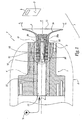
- the projection device or projector P shown in FIGS. 1 to 4 is intended to be supplied with coating material from one or more sources S and displaced, for example with a substantially vertical movement represented by the double arrow F 1 , in O objects look to be coated in an installation I coating these objects.
- the projector P comprises a turbine of which only the central portion 1 is shown which includes a rotor 11 and which is surrounded by a protective cover 2.
- a bowl 3 is intended to be mounted on the rotor 11 and rotated by it, about an axis X-X ', at a speed of several tens of thousands of revolutions per minute, for example 80,000 revolutions / minute. minute, so that the coating product from the source S is sprayed towards an object O, as represented by the arrows F 2 .
- the projector P can be of type electrostatic, that is to say, to include means of electrostatic charge of the front coating product or after it has been unloaded from Ridge 31 of bowl 3.
- the bowl 3 is formed of two parts, namely a hub 32 and a cup portion 33 which defines a surface 34 of flow and distribution of the coating product in the direction of the edge 31.
- the hub 32 is hollow and defines a longitudinal channel 35 which is centered on an axis X 3 -X ' 3 which coincides with the axis XX' when the bowl 3 is mounted on the rotor 1.
- This channel 35 communicates via radial openings 35a with the surface 34.
- the hub 32 constitutes a male part of the bowl 3 which is intended to be introduced into a housing 12 of the rotor 11 centered on the X-X 'axis and extending a channel 15 supply of the bowl 3 in coating product.
- a injection pipette 4 may be provided in channel 15 as shown, in phantom only, in the figure 1.
- the channel 15 communicates with the housing 12 through an area 16 of reduced diameter.
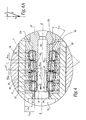
- a cartridge 5 having four annular magnets 51 to parallelepiped section and five magnetic bodies 52 interposed between two magnets 51 adjacent and arranged on both sides of the outside magnets.
- the bodies 52 can be made of any suitable material, for example example steel.
- the magnets 51 all have substantially the same width L 51 taken in a radial direction with respect to the X-X 'axis.
- the magnetic bodies 52 have a width l 52 , measured in the same direction, which increases from the side 53 of the cartridge 5 facing the outside of the rotor 1 towards the duct 15.
- a watertight and nonmagnetic partition 54 is placed in abutment on the edges 52 a of the bodies 52 protruding with respect to the magnets 51 in the direction of the axis X-X ', this partition making it possible to protect, against the mechanical and chemical aggressions, the magnets 51.
- the partition 54 comprises a first portion 54 1 circular cylindrical and centered on the axis XX 'and a second frustoconical portion 54 and divergent 2 towards the side 53 of the cartridge 5, that is to say towards the outlet 12 has the housing 12 outward of the rotor 1.
- the portion 54 2 of the partition 54 is extended by the internal radial surface 55 1 of a shim 55, the half opening angle ⁇ 55 of the frustoconical surface 55 1 being greater than the half-opening angle ⁇ 54 of the surface inside part 54 2 .
- edges 52 have bodies 52 which protrude from the elements 51 are bevelled to match the shape of the outer surface of the partition 54.
- the cartridge 5 defines a volume V 5 receiving the hub 32 of the bowl 3.
- This volume V 5 is delimited by the inner surface of the portion 54 2 which corresponds to a frustoconical geometric surface S 5 and half -angle at the top ⁇ 54 .
- the outer radial surface 32 of the hub 32 is provided with four ribs 36 which are integral with the hub 32, itself made of a magnetic material such as steel. These ribs form radial flanges external to the hub 32 and have, with the exception of the rib 36 closest to the free end 32b of the hub 32, their respective external radial surfaces frustoconical and inscribed in a geometric surface S 3 centered on the longitudinal axis X 3 -X ' 3 , converging towards the free end 32 b of the part 32 and the half-angle at the apex ⁇ 3 .
- the value of the half angle ⁇ 3 is chosen equal to the value of the half angle ⁇ 54 .
- the magnetic coupling force E obtained when the bowl is mounted on the rotor 11 and ready to rotate, has an axial component E 1 , which is non-zero and parallel to the axis xx 'of rotation of the bowl 3 and a component E 2 radial with respect to this axis and also non-zero. This effort is exerted between the elements 52 and 36, through the partition 54.
- the component E 2 has an intensity greater than that of the component E 1 , which is closer to the value of the half angle ⁇ 54 and the relative position of the elements 52 and 36 in the mounted configuration of the bowl 3.
- the thickness e 36 of the ribs 36 taken parallel to the axis X 3 -X ' 3 is substantially equal to the thickness e 52 of the magnetic bodies 52, whereas the spacing d between the ribs 36 is substantially equal to the spacing of two bodies 52, that is to say the thickness e 51 of a magnet 51 taken parallel to the axis X-X '.
- the magnets 51 are identical to each other, whereas the bodies 52 all have the same thickness, their width taken perpendicularly to the axis X-X 'being variable as explained above.
- the ribs or collars circumferential 36 participate in the closing of the field magnetic created by the magnets 51 and that is propagated by magnetic bodies 52.
- FIG. 4 shows a slight offset ⁇ along the axis XX 'between the ribs 36 and the bodies 52. This shift has the effect of exerting on the hub 2 a force F 4 , due to the component E 1 the magnetic force E directed upstream of the duct 15, which has the effect of firmly press the hub 32 inside the cartridge 5 and thus immobilize the bowl 3 relative to the rotor 1.
- the offset ⁇ is progressively increased and the magnetic coupling force gradually decreases, which avoids the sudden movements and the risks for the operator to escape the bowl 3
- the relative values of the components E 1 and E 2 can vary with respect to each other.
- the ribs 36 are produced by surface machining of the surface 32 of the hub 32.
- the ribs or flanges may be formed by rings reported on the hub 32.
- the bowl is without magnets, which makes it particularly attractive on the economic level.
- An O-ring 6 is mounted in the area 16 of reduced diameter and receives the support portion 54 1 of the partition 54, which allows to further isolate the compartment of the cartridge 5 which contains the magnets with respect to the volume of passage of coating and / or cleaning products.
- the partition 54 may not be prolonged up to the level of zone 16, in which case the seal 6 comes resting against the end portion of the hub 32. then provide that zone 16 is slightly conical so to facilitate assembly.
- radial grooves of the gear tooth type, can be machined or reported on the internal radial surface of the cartridge 5 and on the hub 32, this to ensure holding the bowl, and in particular to limit slippage radial and / or tangential of it with respect to magnets, during transient acceleration or deceleration.
- the rotor 111 of this embodiment also forms a feed channel 115. in coating products of a bowl 103 which comprises a hub 132 and a portion 133 provided with a spray edge 131. Magnets 137 are mounted around the hub 132 and are separated in pairs by a magnetic body 136 constituted by ribs or rings attached to the hub 132.
- a cartridge 105 is mounted in a housing 112 formed at the outlet of the channel 115 and comprises a magnetic ring provided with internal ribs or flanges 152 whose thickness and spacing, taken parallel to the direction of the axis XX 'of rotation of the rotor 101, are respectively equal to the thickness and spacing of the bodies 136, taken parallel to the central axis X 103 -X ' 103 of the bowl 103.
- This embodiment corresponds in practice to first embodiment to which a structure reversal between the part carrying the magnets, here the bowl 103, and the part equipped with ribs constituting the induced poles of magnetic coupling, here the rotor 111.
- the volume V 105 for receiving the hub 132 in the housing 112 is divergent towards the outlet 112 of the housing and the geometry of the surfaces defining this volume and the outer casing of the hub, respectively, is chosen to allow a support surface of the hub in the cartridge.
- the rotor 211 of this embodiment also forms a feed channel 215.
- coating material of a bowl 203 which comprises a hub 232 and a portion 233 provided with a spraying edge 231.
- the rotor 211 is equipped with a hollow central shaft 217 on which are mounted magnets 251 separated by bodies 252 and at the center of which extends the channel 215 in the form of a channel 217 b of reduced diameter. This channel 217 b supplies the bowl 203 with coating and / or cleaning products.
- the hub 232 forms a housing 212 for receiving the shaft 217 when the bowl 203 is mounted on the rotor 211.
- the inner surface of the hub 232 is provided with ribs 236 which extend towards the axis X 203 -X ' 203 and are intended to be approximately aligned with the bodies 252 to form the poles induced by the elements 251 and 252 when a magnetic coupling is obtained between the elements 211 and 203.
- the coupling effort magnet obtained has a radial component with respect to the X-X 'axis.
- a sealed and non-magnetic partition 238 may be mounted in abutment on the ribs 236 and the inner surface S 6 is divergent towards the outlet 212 of the housing 212, while the outer surface of the magnets 251 and body 252 is convergent in the direction of the free end 217 of the shaft 217, which facilitates the mechanical centering of the elements 203 and 207 relative to each other.
- the thickness of the ribs 236 is chosen substantially equal to the thickness of the bodies 252 taken parallel to the X-X 'axis, their spacings relative values are also substantially equal.
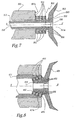
- the rotor 311 of this embodiment also forms a supply channel 315.
- a bowl 303 which includes a hub 332 to be inserted in a recess 360 defined at the center of an annular cartridge 305 attached to the front face 301 has a housing 301 wherein the rotor 311 can rotate about its axis central X-X '.
- the cartridge 305 comprises three magnets 351 as well as four ferro-magnetic bodies 352 in the form of washers, these bodies 352 being intended to be approximately aligned with external radial ribs 336 formed on the outer radial surface of the means 332.
- the magnets 351 and the washers 352 are circular and centered on the X-X 'axis. North and South polarities magnets 351 are opposed two by two, as in the modes previous embodiments.
- Ribs 336 could also be reported on the hub 332.
- the hub 332 is hollow and provided with an internal radial surface 338 which is tapered and against which abuts the front end truncated cone 311 has the rotor 311, which allows engagement of the bowl 303 on the rotor 311, like a Morse taper.
- the elements 336 and 352 are not perfectly aligned in the mounted configuration of the bowl, such 7, so that the magnetic coupling force generated also has a left-handed component in FIG. 7, which tends to firmly press the bowl 303 onto the rotor 311.
- the magnets 451 and the magnetic bodies 452 are arranged with a frustoconical configuration, the bowl 403 having, meanwhile, a hub 432 whose outer surface is frustoconical and converging towards the rear of the rotor 411, this surface being equipped with ribs 436 intended to be, at least approximately, in alignment with the bodies 452.
- An advantage of this embodiment is that it makes it possible to obtain an intensity-calibrated fastening force by eliminating a possible "magnetic detent" effect which may be displeasing to the operator.
- the conicity of the magnets 451 is chosen sufficient so that the successive air gaps are greater than the attraction distance, up to the mounted position of the bowl 403, the quality of the magnets and the precision of the assembly to define this taper.
- This embodiment also has the advantage of good compactness in the direction of the axis XX 'and a possibility of pre-positioning of the bowl 403 in the front end 411 of the rotor 411 during its assembly.
- the relative spacing of the ribs 36 and equivalent may be chosen equal to a submultiple of the width 51 of the magnets 51, that is to say the relative spacing magnetic bodies 52 and the like. Indeed, an alignment of certain ribs 36 or equivalent with the bodies 52 and the like remain possible, some other ribs then being opposite the magnets 51. These other ribs are then not very functional for the desired magnetic coupling. This is applicable to all the embodiments envisaged.
- the spacing d may be equal to a multiple of the spacing of the body 52.
- some of the bodies 52 are opposite an intermediate region between two ribs 36 or equivalent. This can also be applied to all contemplated embodiments.
- the invention has been represented with bowls 3, 103 or 203 bipartite. It is also applicable with a bowl whose product distribution part and hub are monoblock.
- the representation of bowls 303 and 403 is very schematic.
- the invention is applicable regardless of the nature exact product, projected, liquid or powdery, water soluble or not.
- the invention operates with electrostatic projectors or not. Characteristics techniques of the described embodiments may be combined within the framework of this invention.
- the invention is applicable regardless of the number the exact magnet (s) and rib (s) used, the number of ribs (s) being, in practice, adapted to the number Magnet (s).
Abstract
Description
L'invention a trait à un bol de pulvérisation pour un projecteur rotatif de produit de revêtement. L'invention a également trait à un dispositif de projection de produit de revêtement comprenant un tel bol, ainsi qu'à une installation de projection de produit de revêtement incorporant un tel dispositif.The invention relates to a spray bowl for a rotating coating product projector. The invention also relates to a product projection device of coating comprising such a bowl, as well as coating product projection installation incorporating such a device.
Dans une installation de projection de produit de revêtement, il est connu de pulvériser le produit au moyen d'un élément rotatif dénommé bol ou coupelle, alimenté en produit et tournant à une vitesse comprise entre 2 000 et 100 000 tours/minute. Aux vitesses considérées, le bol doit être le plus léger possible et équilibré afin d'éviter, autant que faire se peut, les balourds, notamment si ses moyens d'entraínement comprennent une turbine à palier à air et/ou magnétique.In a product projection installation of coating, it is known to spray the product by means of a rotary element called bowl or cup, powered by produced and rotating at a speed of between 2,000 and 100,000 rpm. At the speeds considered, the bowl must to be as light as possible and balanced to avoid as far as possible, the unbalanced, especially if its means of training include a bearing turbine to air and / or magnetic.
Il est connu, par exemple de WO=A-94/12 286, de relier
un bol à un rotor au moyen d'une couronne d'emboítement
susceptible d'expansion radiale. Selon le préambule de la revendication 1, il est également connu,
par exemple de WO-A-01/62 396 ou de US-A-4,473,188,
d'utiliser des moyens de couplage magnétique entre un bol
et le rotor d'une turbine. Dans ces dispositifs, l'effort à
exercer pour désaccoupler le bol du rotor doit être
intense. Dès que ces éléments sont séparés, l'effort de
couplage magnétique décroít très fortement, de sorte que
rien ne s'oppose au mouvement d'arrachement du bol. Il en
résulte un risque pour un opérateur d'échapper un bol lors
de son démontage, car l'effort résistant du couplage
magnétique chute très rapidement dès que le bol est séparé
du rotor. It is known, for example from WO = A-94/12 286, to connect
a bowl to a rotor by means of a nesting crown
likely to expand radially. According to the preamble of
Or, la chute d'un tel bol conduit généralement à l'endommagement de son arête de pulvérisation, ce qui dégrade la qualité de la pulvérisation obtenue. En d'autres termes, lorsqu'un bol chute sur le sol, il n'est pas rare de devoir le remplacer, alors qu'un tel matériel est, de part le soin apporté à sa réalisation, coûteux. Les dispositifs connus comprennent un ou plusieurs aimants constituant ensemble un dispositif d'aimantation annulaire. Ceci impose à ce ou ces aimants d'être suffisamment volumineux pour générer un champ magnétique intense, ce qui nuit à la compacité du projecteur. En outre, le poids et l'inertie du bol sont relativement importants, tout particulièrement dans le cas où le bol porte le ou les aimants permanents. Enfin, les aimants doivent faire l'objet d'un montage mécanique particulier afin qu'ils ne risquent pas d'éclater sous l'effet des efforts centrifuges.However, the fall of such a bowl usually leads to damage to its spray edge, which degrades the quality of the spray obtained. In others terms, when a bowl falls on the ground, it is not uncommon to have to replace it, whereas such material is, of part of the care taken in its realization, expensive. The known devices include one or more magnets together forming an annular magnetization device. This requires that one or more magnets to be sufficiently bulky to generate an intense magnetic field, which night to the compactness of the projector. In addition, the weight and the inertia of the bowl are relatively important, all especially in the case where the bowl carries the permanent magnets. Finally, magnets must do subject of a particular mechanical assembly so that they do not not likely to burst as a result of the efforts Centrifugal.
C'est à ces inconvénients qu'entend plus particulièrement remédier l'invention, en proposant un bol de pulvérisation qui peut être aisément entraíné par un rotor prévu à cet effet, grâce à un couplage magnétique efficace, tout en permettant un montage et un démontage aisé du bol, en début et en fin de service.It is to these disadvantages that more particularly remedy the invention, by proposing a bowl spray which can easily be driven by a rotor provided for this purpose, thanks to a magnetic coupling efficient, while allowing assembly and disassembly easy bowl, at the beginning and end of service.
Dans cet esprit, l'invention concerne un bol de pulvérisation pour un projecteur rotatif de produit de revêtement, ce bol étant équipé de moyens de couplage magnétique avec un organe d'entraínement en rotation ou avec un boítier entourant cet organe, caractérisé en ce que ces moyens de couplage magnétique sont aptes à coopérer avec des moyens complémentaires portés par l'organe d'entraínement ou par le boítier, de telle manière que l'effort de couplage magnétique obtenu a une composante radiale par rapport à l'axe de rotation de ce bol. In this spirit, the invention relates to a bowl of spraying for a rotating product projector coating, this bowl being equipped with coupling means magnet with a rotating drive member or with a housing surrounding this organ, characterized in that these magnetic coupling means are able to cooperate with complementary means carried by the organ of training or by the housing, so that the magnetic coupling effort obtained has a component radial with respect to the axis of rotation of this bowl.
Grâce à l'invention, l'effort du couplage magnétique obtenu est efficace, alors que les moyens de couplage prévus sur le bol participent au couplage magnétique entre le bol et l'organe d'entraínement ou le boítier, y compris lors des mouvements de mise en place ou de démontage du bol par rapport au projecteur, ce qui confère une progressivité satisfaisante à l'effort devant être vaincu ou accompagné par l'opérateur à cette occasion.Thanks to the invention, the magnetic coupling effort obtained is effective, while the coupling means provided on the bowl participate in the magnetic coupling between the bowl and the drive member or the housing, including during the movements of setting up or disassembling the bowl compared to the projector, which gives a progressiveness satisfactory to the effort to be defeated or accompanied by the operator on this occasion.
En outre, un bol de pulvérisation pour projecteur peut
incorporer une ou plusieurs des caractéristiques de l'une
des revendications 2 à 8.In addition, a projector spray bowl can
incorporate one or more of the characteristics of one
L'invention concerne également un dispositif de projection de produit de revêtement qui comprend un bol et un organe apte à entraíner ce bol, des moyens de couplage magnétique incluant au moins un aimant permanent étant prévus entre le bol et l'organe précité ou entre le bol et un boítier entourant cet organe. Ce dispositif est caractérisé en ce que les moyens de couplage sont disposés de telle manière que l'effort de couplage magnétique a une composante radiale par rapport à l'axe de rotation du bol.The invention also relates to a device for projection of coating product which includes a bowl and a member adapted to drive this bowl, coupling means magnetic circuit including at least one permanent magnet being provided between the bowl and the aforementioned organ or between the bowl and a housing surrounding this organ. This device is characterized in that the coupling means are arranged in such a way that the magnetic coupling force has a radial component relative to the axis of rotation of the bowl.
De façon avantageuse, ces moyens de couplage magnétique comprennent, en outre, au moins un corps magnétique associé à l'aimant et monté sur l'un des deux éléments que sont le bol et l'organe d'entraínement ou le bol et le boítier, alors que l'autre élément porte au moins une nervure formée dans un matériau magnétique. Dans un tel dispositif, les nervures constituent les pôles induits d'un dispositif de couplage magnétique dont les corps magnétiques associé aux aimants forment les pôles inducteurs.Advantageously, these coupling means magnetic, furthermore, include at least one body magnet associated with the magnet and mounted on one of the two elements that are the bowl and the drive member or the bowl and the housing, while the other element carries at least a rib formed in a magnetic material. In such a device, the ribs constitute the induced poles of a magnetic coupling device whose bodies magnets associated with magnets form the poles inducers.
Avantageusement, l'épaisseur de la ou des nervure(s) est sensiblement égale à l'épaisseur des corps magnétiques. De même, lorsque le dispositif comprend plusieurs corps magnétiques et plusieurs nervures, l'écartement relatif de ces nervures est avantageusement sensiblement égal à, ou correspond sensiblement à un multiple ou un sous-multiple de l'écartement relatif d'effort magnétique. Le positionnement et la géométrie de ces nervures sont ainsi adaptés en fonction du positionnement et de la géométrie des masses polaires constituées par les corps magnétiques, pour optimiser l'effet de couplage recherché. Ces nervures permettent une concentration du champ électromagnétique à leur niveau, d'où une amélioration du couplage magnétique obtenu.Advantageously, the thickness of the rib (s) is substantially equal to the thickness of the magnetic bodies. Similarly, when the device comprises several bodies magnetic and several ribs, the relative spacing of these ribs is advantageously substantially equal to, or corresponds substantially to a multiple or a sub-multiple the relative spacing of magnetic force. The positioning and the geometry of these ribs are well adapted according to positioning and geometry polar masses constituted by the magnetic bodies, to optimize the desired coupling effect. These ribs allow a concentration of the electromagnetic field to their level, hence an improvement of the magnetic coupling got.
Par ailleurs, un dispositif de projection peut incorporer les caractéristiques de l'une des revendications 13 à 21.Moreover, a projection device can incorporate the features of one of the claims 13 to 21.
L'invention concerne enfin une installation de projection de produit de revêtement, qui comprend au moins un dispositif de projection tel que précédemment décrit.Finally, the invention relates to an installation of coating product projection, which includes at least a projection device as previously described.
L'invention sera mieux comprise et d'autres avantages de celle-ci apparaítront plus clairement à la lumière de la description qui va suivre de cinq modes de réalisation d'un dispositif de projection de produit de revêtement comprenant un bol conforme à l'invention, donnée uniquement à titre d'exemple et faite en référence aux dessins annexés dans lesquels :
- la figure 1 est une coupe longitudinale de principe d'un projecteur de produit de revêtement conforme à un premier mode de réalisation de l'invention, incorporant un bol conforme à un premier mode de réalisation et faisant partie d'une installation conforme à l'invention ;
- la figure 2 est une coupe longitudinale du rotor et une vue de côté du bol du dispositif de la figure 1 ;
- la figure 3 est une vue en perspective avec arrachement partiel des éléments représentés à la figure 2 ;
- la figure 4 est une vue à plus grande échelle du détail IV à la figure 1 ;
- la figure 4A est une représentation vectorielle de l'effort de couplage magnétique dans la configuration de la figure 4 ;
- la figure 5 est une vue analogue à la
figuré 2 pour un dispositif de projection et un bol conformes à un deuxième mode de réalisation de l'invention ; - la figure 6 est une vue analogue à la figure 2 pour un dispositif de projection et un bol conformes à un troisième mode de réalisation de l'invention ;
- la figure 7 est une coupe longitudinale de principe d'un dispositif conforme à un quatrième mode de réalisation de l'invention et
- la figure 8 est une coupe analogue à la figure 7 pour un cinquième mode de réalisation de l'invention.
- Figure 1 is a longitudinal sectional view of a coating product projector according to a first embodiment of the invention, incorporating a bowl according to a first embodiment and forming part of an installation according to the invention;
- Figure 2 is a longitudinal section of the rotor and a side view of the bowl of the device of Figure 1;
- Figure 3 is a perspective view partially cut away of the elements shown in Figure 2;
- Figure 4 is an enlarged view of detail IV in Figure 1;
- Fig. 4A is a vector representation of the magnetic coupling force in the configuration of Fig. 4;
- Figure 5 is a view similar to Figure 2 for a projection device and a bowl according to a second embodiment of the invention;
- Figure 6 is a view similar to Figure 2 for a projection device and a bowl according to a third embodiment of the invention;
- FIG. 7 is a longitudinal sectional view of a device according to a fourth embodiment of the invention and
- Figure 8 is a section similar to Figure 7 for a fifth embodiment of the invention.
Le dispositif de projection ou projecteur P représenté
aux figures 1 à 4 est destiné à être alimenté en produit de
revêtement à partir d'une ou plusieurs sources S et
déplacé, par exemple avec un mouvement essentiellement
vertical représenté par la double flèche F1, en regard
d'objets O à revêtir au sein d'une installation I de
revêtement de ces objets. Le projecteur P comprend une
turbine dont seul est représenté la partie centrale 1 qui
inclut un rotor 11 et qui est entourée par un capotage 2 de
protection. Un bol 3 est destiné à être monté sur le rotor
11 et mis en rotation par celui-ci, autour d'un axe X-X', à
une vitesse de plusieurs dizaines dé milliers de tours par
minute, par exemple 80 000 tours/minute, de telle sorte que
le produit de revêtement provenant de la source S est
pulvérisé en direction d'un objet O, comme représenté par
les flèches F2.The projection device or projector P shown in FIGS. 1 to 4 is intended to be supplied with coating material from one or more sources S and displaced, for example with a substantially vertical movement represented by the double arrow F 1 , in O objects look to be coated in an installation I coating these objects. The projector P comprises a turbine of which only the
Selon un aspect avantageux de l'invention qui n'est
pas représenté, le projecteur P peut être de type
électrostatique, c'est-à-dire comprendre des moyens de
charge électrostatique du produit de revêtement avant ou
après que celui-ci a été déchargé à partir de l'arête 31 du
bol 3.According to an advantageous aspect of the invention which is not
not shown, the projector P can be of type
electrostatic, that is to say, to include means of
electrostatic charge of the front coating product or
after it has been unloaded from Ridge 31 of
Le bol 3 est formé de deux pièces, à savoir un moyeu
32 et une partie 33 formant coupelle qui définit une
surface 34 d'écoulement et de répartition du produit de
revêtement en direction de l'arête 31. Le moyeu 32 est
creux et définit un canal longitudinal 35 qui est centré
sur un axe X3-X'3 qui est confondu avec l'axe X-X' lorsque
le bol 3 est monté sur le rotor 1.The
Ce canal 35 communique par des ouvertures radiales 35a
avec la surface 34.This
Le moyeu 32 constitue une partie mâle du bol 3 qui est
destinée à être introduite dans un logement 12 du rotor 11
centré sur l'axe X-X' et qui prolonge un canal 15
d'alimentation du bol 3 en produit de revêtement. Une
pipette d'injection 4 peut être prévue dans le canal 15
comme représenté, en traits mixtes uniquement, à la figure
1.The
Le canal 15 communique avec le logement 12 à travers
une zone 16 de diamètre réduit.The
A l'intérieur du logement 12 est disposée une
cartouche 5 comportant quatre aimants annulaires 51 à
section parallélépipédique et cinq corps magnétiques 52
intercalés entre deux aimants 51 adjacents et disposés de
part et d'autre des aimants extérieurs. Les corps 52
peuvent être réalisés dans tout matériau approprié, par
exemple en acier. Inside the
Les aimants 51 ont tous sensiblement la même largeur
l 51 prise selon une direction radiale par rapport à l'axe X-X'.
En revanche, les corps magnétiques 52 ont une largeur
l 52, mesurée selon la même direction, qui va croissant
depuis le côté 53 de la cartouche 5 tourné vers l'extérieur
du rotor 1 vers le conduit 15.The
Une cloison étanche et amagnétique 54 est disposée en
appui sur les bords 52a des corps 52 faisant saillie par
rapport aux aimants 51 en direction de l'axe X-X', cette
cloison permettant de protéger, contre les agressions
mécaniques et chimiques, les aimants 51.A watertight and
La cloison 54 comprend une première partie 541
cylindrique à base circulaire et centrée sur l'axe X-X' et
une seconde partie 542 tronconique et divergente en
direction du côté 53 de la cartouche 5, c'est-à-dire en
direction du débouché 12a du logement 12 tourné vers
l'extérieur du rotor 1.The
La partie 542 de la cloison 54 est prolongée par la
surface radiale interne 551 d'une cale 55, le demi angle
d'ouverture α55 de la surface tronconique 551 étant
supérieur au demi angle d'ouverture α54 de la surface
intérieure de la partie 542.The
Les bords 52a des corps 52 qui font saillie par
rapport aux éléments 51 sont biseautés pour épouser la
forme de la surface externe de la cloison 54.The
Dans sa partie centrale, la cartouche 5 définit un
volume V5 de réception du moyeu 32 du bol 3. Ce volume V5
est délimité, par la surface interne de la partie 542 qui
correspond à une surface géométrique S5 tronconique et de
demi-angle au sommet α54.In its central part, the
La surface radiale externe 32a du moyeu 32 est pourvue
de quatre nervures 36 qui sont monoblocs avec le moyeu 32,
lui même réalisé dans un matériau magnétique, tel que
l'acier. Ces nervures forment des collerettes radiales
externes par rapport au moyeu 32 et ont, à l'exception de
la nervure 36 la plus proche de l'extrémité libre 32b du
moyeu 32, leurs surfaces radiales externes respectives
tronconiques et inscrites dans une surface géométrique S3
centrée sur l'axe longitudinal X3-X'3, convergente en
direction de l'extrémité libre 32b de la partie 32 et de
demi angle au sommet α3. La valeur du demi angle α3 est
choisie égale à la valeur du demi angle α54.The outer
Ainsi, lors de la mise en place du bol 3 sur le rotor
1 et après alignement des axes X-X' et X3-X'3; il est
possible de faire coïncider les surfaces S3 et S5, ce qui
permet un appui surfacique des surfaces radiales externes
36a de la plupart des nervures ou collerettes 36 sur la
cloison 54.Thus, during the establishment of the
On atteint alors la position des figures 1 et 4 où les
lignes L de champ magnétique dues aux aimants 51 se
referment à travers les éléments 52 et 36, en passant
également dans les parties principales des éléments 51 et
32.We then reach the position of FIGS. 1 and 4 where the
Magnetic field L lines due to the
Dans cette configuration, l'effort E de couplage
magnétique obtenu, lorsque le bol est monté sur le rotor 11
et prêt à tourner, a une composante E1 axiale, non nulle et
parallèle à l'axe x-x' de rotation du bol 3 et une
composante E2 radiale par rapport à cet axe et également non
nulle. Cet effort s'exerce entre les éléments 52 et 36, à
travers la cloison 54.In this configuration, the magnetic coupling force E obtained, when the bowl is mounted on the
En pratique, la composante E2 a une intensité
supérieure à celle de la composante E1, ce qui est a
rapprocher de la valeur du demi-angle α54 et de la position
relative des éléments 52 et 36 en configuration montée du
bol 3. In practice, the component E 2 has an intensity greater than that of the component E 1 , which is closer to the value of the half angle α 54 and the relative position of the
Pour amplifier ce phénomène de bouclage magnétique,
l'épaisseur e 36 des nervures 36 prises parallèlement à l'axe
X3-X'3 est sensiblement égale à l'épaisseur e 52 des corps
magnétiques 52, alors que l'espacement d entre les nervures
36 est sensiblement égal à l'espacement d' de deux corps
52, c'est-à-dire à l'épaisseur e 51 d'un aimant 51 prise
parallèlement à l'axe X-X'.To amplify this magnetic looping phenomenon, the thickness e 36 of the
Les aimants 51 sont identiques entre eux, alors que
les corps 52 ont tous la même épaisseur, leur largeur prise
perpendiculairement à l'axe X-X' étant variable comme
expliqué ci-dessus.The
Au vu de ce qui précède, les nervures ou collerettes
circonférentielles 36 participent à la fermeture du champ
magnétique créé par les aimants 51 et qui se propage par
les corps magnétiques 52.In view of the above, the ribs or collars
circumferential 36 participate in the closing of the field
magnetic created by the
On note à la figure 4 un léger décalage Δ le long de
l'axe X-X' entre les nervures 36 et les corps 52. Ce
décalage a pour effet d'exercer sur le moyeu 2 un effort F4,
dû à la composante E1 de l'effort magnétique E dirigée vers
l'amont du conduit 15, ce qui a pour effet de plaquer
fermement le moyeu 32 à l'intérieur de la cartouche 5 et
d'immobiliser ainsi le bol 3 par rapport au rotor 1.FIG. 4 shows a slight offset Δ along the axis XX 'between the
Lorsqu'on démonte le bol 3 par rapport au reste du
projecteur P, on augmente progressivement le décalage Δ et
l'effort de couplage magnétique diminue progressivement, ce
qui évite les mouvements brusques et les risques pour
l'opérateur d'échapper le bol 3. Dans ce cas, les valeurs
relatives des composantes E1 et E2 peuvent varier l'une par
rapport à l'autre.When the
Dans l'exemple représenté, les nervures 36 sont
réalisées par usinage superficiel de la surface 32a du
moyeu 32. Selon une variante non représentée de
l'invention, ces nervures ou collerettes pourraient être
formées par des bagues rapportées sur le moyeu 32.In the example shown, the
Dans ce premier mode de réalisation, le bol est dépourvu d'aimants, ce qui le rend particulièrement attractif sur le plan économique.In this first embodiment, the bowl is without magnets, which makes it particularly attractive on the economic level.
Un joint torique 6 est monté dans la zone 16 de
diamètre réduit et reçoit en appui la partie 541 de la
cloison 54, ce qui permet d'isoler encore plus parfaitement
le compartiment de la cartouche 5 qui renferme les aimants
par rapport au volume de passage des produits de revêtement
et/ou de nettoyage.An O-
En variante, la cloison 54 peut ne pas se prolonger
jusqu'au niveau de la zone 16, auquel cas le joint 6 vient
en appui contre la partie d'extrémité du moyeu 32. On peut
alors prévoir que la zone 16 soit légèrement conique afin
de faciliter le montage.Alternatively, the
Selon une variante non représentée de l'invention, des
cannelures radiales, de type dents d'engrenage, peuvent
être usinées ou rapportées sur la surface radiale interne
de la cartouche 5 et sur le moyeu 32, ceci afin d'assurer
la tenue du bol, et notamment de limiter le glissement
radial et/ou tangentiel de celui-ci par rapport aux
aimants, lors des régimes transitoires d'accélération ou de
décélération. Dans ce cas, il est nécessaire de prévoir un
jeu axial et radial pour le montage avec ces cannelures, de
façon à conserver un centrage satisfaisant de la partie
conique du bord par rapport aux aimants.According to a not shown variant of the invention,
radial grooves, of the gear tooth type, can
be machined or reported on the internal radial surface
of the
Dans le second mode de réalisation de l'invention
représenté à la figure 5, les éléments analogues à ceux du
premier mode de réalisation portent des références
identiques augmentées de 100. Le rotor 111 de ce mode de
réalisation forme également un canal 115 d'alimentation en
produits de revêtement d'un bol 103 qui comprend un moyeu
132 et une partie 133 pourvue d'une arête 131 de
pulvérisation. Des aimants 137 sont montés autour du moyeu
132 et sont séparés deux à deux par un corps magnétique 136
constitué par des nervures ou des bagues rapportées sur le
moyeu 132. Une cartouche 105 est montée dans un logement
112 formé au débouché du canal 115 et comprend une bague
magnétique pourvue de nervures ou collerettes internes 152
dont l'épaisseur et l'écartement, pris parallèlement à la
direction de l'axe X-X' de rotation du rotor 101, sont
respectivement égaux à l'épaisseur et à l'écartement des
corps 136, pris parallèlement à l'axe central X103-X'103 du
bol 103.In the second embodiment of the invention shown in FIG. 5, elements similar to those of the first embodiment carry identical references increased by 100. The
Ce mode de réalisation correspond en pratique au
premier mode de réalisation auquel a été appliquée une
inversion de structure entre la partie portant les aimants,
ici le bol 103, et la partie équipée de nervures
constituant les pôles induits de couplage magnétique, ici
le rotor 111.This embodiment corresponds in practice to
first embodiment to which a
structure reversal between the part carrying the magnets,
here the
Comme précédemment ; le volume V105 de réception du
moyeu 132 dans le logement 112 est divergent en direction
du débouché 112a de ce logement et la géométrie des
surfaces définissant respectivement ce volume et
l'enveloppe externe du moyeu est choisie pour permettre un
appui surfacique du moyeu dans la cartouche.Like before ; the volume V 105 for receiving the
Dans le troisième mode de réalisation de l'invention
représenté à la figure 6, les éléments analogues à ceux du
premier mode de réalisation portent des références
identiques augmentées de 200. Le rotor 211 de ce mode de
réalisation forme également un canal 215 d'alimentation en
produit de revêtement d'un bol 203 qui comprend un moyeu
232 et une partie 233 pourvue d'une arête de pulvérisation
231. Le rotor 211 est équipé d'un arbre central creux 217
sur lequel sont montés des aimants 251 séparés par des
corps magnétiques 252 et au centre duquel se prolonge le
canal 215 sous la forme d'un canal 217b de diamètre réduit.
Ce canal 217b permet d'alimenter le bol 203 en produits de
revêtement et/ou de nettoyage.In the third embodiment of the invention shown in FIG. 6, elements similar to those of the first embodiment carry identical references increased by 200. The
Le moyeu 232 forme un logement 212 de réception de
l'arbre 217 lorsque le bol 203 est monté sur le rotor 211.The
On note respectivement X203-X'203 de l'axe de symétrie
du bol 203 et X-X' l'axe de rotation du rotor 211. Ces axes
sont confondus lorsque le bol 203 est monté sur le rotor
211.Note X 203 -X ' 203 respectively of the axis of symmetry of the
La surface interne du moyeu 232 est pourvu de nervures
236 qui s'étendent en direction de l'axe X203-X'203 et sont
destinées à être approximativement alignées avec les corps
252 pour constituer les pôles induits par les éléments 251
et 252 lorsqu'un couplage magnétique est obtenu entre les
éléments 211 et 203.The inner surface of the
Comme précédemment, dans ce cas, l'effort de couplage magnétique obtenu a une composante radiale par rapport à l'axe X-X'.As before, in this case, the coupling effort magnet obtained has a radial component with respect to the X-X 'axis.
Une cloison étanche et amagnétique 238 peut être
montée en appui sur les nervures 236 et sa surface interne
S6 est divergente en direction du débouché 212a du logement
212, alors que la surface externe des aimants 251 et des
corps 252 est convergente en direction de l'extrémité libre
217a de l'arbre 217, ce qui facilite le centrage mécanique
des éléments 203 et 207 l'un par rapport à l'autre.A sealed and
Comme précédemment, l'épaisseur des nervures 236 est
choisie sensiblement égale à l'épaisseur des corps 252
prise parallèlement à l'axe X-X', leurs écartements
relatifs étant également sensiblement égaux.As before, the thickness of the
Dans le quatrième mode de réalisation de l'invention
représenté à la figure 7, les éléments analogues à ceux du
premier mode de réalisation portent des références
identiques augmentées de 300. Le rotor 311 de ce mode de
réalisation forme également un canal 315 d'alimentation
d'un bol 303 qui comprend un moyeu 332 destiné à être
introduit dans un logement 360 défini au centre d'une
cartouche annulaire 305 fixée sur la face avant 301a d'un
boítier 301 dans lequel peut tourner le rotor 311 autour de
son axe central X-X'.In the fourth embodiment of the invention shown in FIG. 7, elements similar to those of the first embodiment carry identical references increased by 300. The
La cartouche 305 comprend trois aimants 351 ainsi que
quatre corps ferro-magnétiques 352 en forme de rondelles,
ces corps 352 étant destinés à être approximativement
alignés avec des nervures radiales externes 336 ménagées
sur la surface radiale externe du moyen 332.The
Les aimants 351 et les rondelles 352 sont circulaires
et centrés sur l'axe X-X'. Les polarités Nord et Sud des
aimants 351 sont opposées deux à deux, comme dans les modes
de réalisation précédents.The
Les nervures 336 pourraient également être rapportées
sur le moyeu 332.
Comme dans les modes de réalisation précédents, un
effort magnétique est exercé entre les éléments 305 et 332,
les lignes de champ ayant tendance à se refermer à travers
les éléments 352 et 336. Cet effort à une composante
radiale.As in the previous embodiments, a
magnetic force is exerted between the
Par ailleurs, le moyeu 332 est creux et pourvu d'une
surface radiale interne 338 qui est tronconique et contre
laquelle vient en butée l'extrémité avant tronconique 311a
du rotor 311, ce qui permet un emboítement du bol 303 sur
le rotor 311, à la façon d'un cône morse. Compte tenu de la
géométrie des éléments 311a, 338 et 336 et du
positionnement des éléments 311 et 305 l'un par rapport à
l'autre, les éléments 336 et 352 ne sont pas tout à fait
alignés en configuration montée du bol, telle que
représenté à la figure 7, de sorte que l'effort de couplage
magnétique engendré à également une composante dirigée vers
la gauche à la figure 7, ce qui tend à plaquer fermement le
bol 303 sur le rotor 311. Furthermore, the
Dans cette configuration, un entrefer cylindrique à
base circulaire existe entre le jeu d'aimants 351 et les
nervures 336.In this configuration, a cylindrical air gap
circular base exists between the magnet set 351 and the
Il est aisé d'ajuster la valeur de l'effort de fixation du bol en fonction de sa taille, de son poids et de sa vitesse de rotation, en jouant sur le nombre d'aimants de la cartouche 305. Les avantages particuliers de ce mode de réalisation sont la faible masse des parties tournantes et la simplicité de réalisation.It is easy to adjust the value of the effort of fixing the bowl according to its size, weight and of its speed of rotation, playing on the number magnets of the 305 cartridge. The special benefits of this embodiment are the low mass of the parts rotating and simplicity of realization.
Dans le cinquième mode de réalisation de l'invention
représenté à la figure 8, les éléments analogues à ceux du
premier mode de réalisation porte des références identiques
augmentées de 400. Les aimants 451 et les corps magnétiques
452 sont disposés avec une configuration tronconique, le
bol 403 ayant, quant à lui, un moyeu 432 dont la surface
externe est tronconique et convergente vers l'arrière du
rotor 411, cette surface étant équipée de nervures 436
destinées à être, approximativement au moins, en alignement
avec les corps 452. La coopération des éléments 451 et 452,
d'une part, et des nervures 436, d'autre part, assure à la
fois la fixation magnétique et le centrage mécanique du bol
dans l'extrémité avant 411a du rotor 411 qui est en forme
d'arbre centré sur son axe de rotation X-X'.In the fifth embodiment of the invention shown in FIG. 8, elements similar to those of the first embodiment carry identical references increased by 400. The
Un avantage de ce mode de réalisation est qu'il permet
d'obtenir un effort de fixation calibré en intensité en
supprimant un éventuel effet de « crantage magnétique » qui
peut déplaire à l'opérateur. La conicité des aimants 451
est choisie suffisante pour que les entrefers successifs
soient supérieurs à la distance d'attraction, jusqu'à la
position montée du bol 403, la qualité des aimants et la
précision du montage permettant de définir cette conicité.
Ce mode de réalisation présente également l'avantage d'une
bonne compacité selon la direction de l'axe X-X' et d'une
possibilité de pré-positionnement du bol 403 dans
l'extrémité avant 411a du rotor 411 lors de son montage.An advantage of this embodiment is that it makes it possible to obtain an intensity-calibrated fastening force by eliminating a possible "magnetic detent" effect which may be displeasing to the operator. The conicity of the
Selon une première variante non représentée de
l'invention, l'écartement relatif des nervures 36 et
équivalentes peut être choisi égal à un sous-multiple de la
largeur l 51 des aimants 51, c'est-à-dire de l'écartement
relatif des corps magnétiques 52 et équivalent. En effet,
un alignement de certaines nervures 36 ou équivalentes avec
les corps 52 et équivalents demeurent possible, certaines
autres nervures se trouvant alors en regard des aimants
51. Ces autres nervures sont alors peu fonctionnelles pour
le couplage magnétique recherché. Ceci est applicable à
tous les modes de réalisation envisagés.According to a first variation not shown of the invention, the relative spacing of the
Selon une autre variante non représentée de
l'invention, l'écartement d peut être égal à un multiple de
l'écartement d' des corps 52. Dans ce cas, certains corps
52 sont en regard d'une zone intermédiaire entre deux
nervures 36 ou équivalentes. Ceci peut également être
appliqué à tous les modes de réalisation envisagés.According to another variant not shown of the invention, the spacing d may be equal to a multiple of the spacing of the
L'invention a été représentée avec des bols 3, 103 ou
203 bipartites. Elle est également applicable avec un bol
dont la partie de répartition du produit et le moyeu sont
monoblocs. La représentation des bols 303 et 403 est très
schématique.The invention has been represented with
L'invention est applicable indépendamment de la nature exacte du produit, projeté, liquide ou pulvérulent, hydrosoluble ou non. L'invention fonctionne avec des projecteurs électrostatiques ou non. Les caractéristiques techniques des modes de réalisation décrits peuvent être combinées entre elles dans le cadre de la présente invention.The invention is applicable regardless of the nature exact product, projected, liquid or powdery, water soluble or not. The invention operates with electrostatic projectors or not. Characteristics techniques of the described embodiments may be combined within the framework of this invention.
Quel que soit le mode de réalisation considéré, les éléments magnétiques, qu'ils s'agissent des aimants ou des nervures associées, sont, une fois le bol monté sur le rotor, situés à l'intérieur des logements 12, 112, 212, 360 ou équivalents, ce qui induit trois avantages supplémentaires par rapport à une construction telle que connue de WO-A-01/162396, à savoir :
- une bonne compacité axiale qui est importante car il convient de réduire le plus possible la dimension axiale d'un pulvérisateur pour atteindre correctement des zones d'un objet à revêtir dont le rayon de courbure faible, telles que les détourages de portes de carrosserie de véhicule automobile. Ceci permet d'améliorer la manoeuvrabilité d'un robot et d'un pulvérisateur incorporant l'invention et de réduire le moment résistant sur le poignet.
- des pertes de peinture minimisées du fait de la compacité axiale obtenue pour le projecteur. Ceci induit également une consommation moindre de produits de rinçage lors des changements des produits de revêtement.
- une protection améliorée des aimants contre les chocs, ces aimants étant fragiles par construction.
- a good axial compactness which is important because it is necessary to reduce as much as possible the axial dimension of a sprayer to correctly reach areas of an object to be coated with a small radius of curvature, such as vehicle body door curvings automobile. This makes it possible to improve the maneuverability of a robot and a sprayer incorporating the invention and to reduce the moment of resistance on the wrist.
- minimized paint losses due to the axial compactness obtained for the projector. This also induces a lower consumption of rinses during the changes of the coating products.
- improved protection of the magnets against shocks, these magnets being fragile by construction.
L'invention est applicable indépendamment du nombre exact d'aimant(s) et de nervure(s) utilisées, le nombre de nervure(s) étant, en pratique, adapté au nombre d'aimant(s).The invention is applicable regardless of the number the exact magnet (s) and rib (s) used, the number of ribs (s) being, in practice, adapted to the number Magnet (s).
Claims (22)
- Spray bowl for rotary discharge device for coating product, said bowl being equipped with magnetic coupling means with a member for driving in rotation or with a casing surrounding said member, characterised in that said magnetic coupling means (36; 136; 236; 336; 436) are capable of cooperating with complementary means carried by said member (11; 111; 211; 411) or said casing (301), such that the magnetic coupling force (E) has a radial component (E2) relative to the axis of rotation (X-X') of said bowl (3; 103; 203; 303; 403).
- Bowl according to claim 1, characterised in that said magnetic coupling means comprise at least one magnetic element (36; 136; 236; 336; 436) which is either arranged around a male part (32; 132; 332; 432) of said bowl (3; 103; 303; 403) capable of being engaged in a central housing (12; 112; 360) of said member (11; 111; 411) or of said casing (301) or arranged within a female part (232) of said bowl (203) forming a housing (212) for receiving a central shaft (217) integral with said member (211).
- Bowl according to claim 2, characterised in that said magnetic elements form radial flanges (36; 136; 236; 336; 436) which extend either toward the exterior from said male part (32; 132; 332; 432), or toward the geometric axis of rotation (X-X') of said bowl from said female part (232).
- Bowl (103) according to one of claims 2 or 3, characterised in that permanent magnets (137) are arranged between each pair of adjacent magnetic elements (136).
- Bowl (3; 203; 303; 403) according to one of claims 2 or 3, characterised in that it is devoid of magnets.
- Bowl according to any one of claims 2 to 5, characterised in that said magnetic elements (36; 136; 236; 436) are included within an enveloping surface (S3) converging in the direction of the free end (32b) of said male part (32; 432) or diverging in the direction of the outlet (212a) of the housing (212) of said female part (232).
- Bowl according to any one of claims 2 to 6, characterised in that said male part (32; 132; 332; 432) is hollow and forms a channel (35) for supplying coating product for a spraying surface (34) and/or edge (31) of said bowl (3; 103).
- Bowl according to any one of the preceding claims, characterised in that it is provided with means (338) for interlocking with said member (311), said magnetic coupling means (336) being arranged around said interlocking means and capable of cooperating with complementary means (352) not driven in rotation by said member, to contribute to a force for interlocking said bowl with said member.
- Discharge device for coating product comprising a bowl and a member capable of driving said bowl in rotation, magnetic coupling means, between said bowl and said member or between said bowl and a casing surrounding said member, being provided and including at least one permanent magnet, characterised in that said coupling means (36; 52; 136; 152; 236; 252; 336; 352; 436, 452) are arranged such that the magnetic coupling force (E) has a radial component (E2) relative to the axis of rotation (X-X') of said bowl (3; 103; 203; 303; 403).
- Device according to claim 9, characterised in that said magnetic coupling means further comprise at least one magnetic body (52; 136; 252; 352; 452) associated with said magnet (51; 137; 251; 351; 451) and mounted on one (11; 103; 211; 301; 411) of the two elements which are said bowl (3; 103; 203; 403) and said member (11; 111; 211; 411) or said bowl (303) and said casing (301), whilst the other element (3; 111; 203; 303; 403) carries at least one rib (36; 152; 236; 336; 436) formed of a magnetic material.
- Device according to claim 10, characterised in that the thickness (e 36) of said rib or ribs (36; 152; 236; 336; 436) is substantially equal to the thickness (e 52) of said body or bodies (52; 136; 252; 352; 452).
- Device according to one of claims 10 or 11, characterised in that it comprises a plurality of magnetic bodies and a plurality of ribs and in that the relative spacing (d) of said ribs (36; 152; 236; 336; 436) is substantially equal or corresponds substantially to a multiple or sub-multiple of the relative spacing (d') of said bodies (52; 136; 252; 352; 452).
- Device according to any one of claims 10 to 13, characterised in that said bowl (3; 103) is provided with a male part (32; 132; 432) around which said ribs (36; 436) or said bodies (136) is or are arranged, whilst said drive member is provided with a central housing (12; 112) for receiving said male part, magnetic coupling elements (51; 52; 152; 452) complementing those carried by said bowl being provided in said housing, around said male part.
- Device according to claim 13, characterised in that said magnet or magnets (51) and the associated magnetic bodies (52) are grouped together in the form of a cartridge (5) arranged in said housing (12) whilst said ribs (36) are provided around said male part (32).
- Device according to one of claims 13 or 14, characterised in that the volume (V5; V105) for receiving (12; 112) said male part (32; 132; 432) in said housing (12; 112) is defined by a surface of revolution (S5) centred on the axis of rotation (X-X') of said drive member (11; 111; 411) and diverging in the direction of the outlet (12a; 112a) of said housing, whilst said ribs (36; 436) or said bodies (136) carried by said male part are included within an enveloping surface (S3) which substantially has the same geometry as that (S5) defining said volume and which converges in the direction of the free end (32b) of said male part.
- Device according to any one of claims 10 to 12, characterised in that said bowl (203) is provided with a female part (232) within which said rib(s) (236) is or are formed, whilst said drive member is provided with a central shaft (217) capable of being engaged in a housing (212) formed in said female part, magnetic coupling elements (252) complementary to those (236) carried by said bowl being mounted on said shaft.
- Device according to claim 16, characterised in that the housing (212) formed in said female part for receiving said shaft (217) is defined by a surface of revolution centred on a central axis of said bowl (X203-X203') and diverging in the direction of the outlet (212a) of said housing, whilst said bodies (252) or said ribs carried by said shaft (217) are included within an enveloping surface which substantially has the same geometry as that defining said housing and which converges in the direction of the free end (217a) of said shaft.
- Device according to any one of claims 9 to 12, characterised in that said bowl is provided with a male part (332) capable of being inserted in a housing (360) defined by a casing (301) surrounding said drive member (311), said male part itself being equipped with means (338) for interlocking with said member.
- Device according to claim 18, characterised in that said interlocking means comprise a truncated bearing surface (338) of a form generally complementary to that of the end (311a) of said member (311).
- Device according to any one of claims 9 to 19, characterised in that said drive member (1; 111; 211; 311; 411) is provided with a central channel (15; 115; 215; 217b) for supplying coating product, whilst said bowl (3; 103; 203; 303; 403) is provided with a central channel (35) for supplying coating product for a discharge surface (34) and/or edge (31; 231), said channels being connected to one another when said bowl is magnetically coupled to said member or to said casing (301), the magnetic coupling taking place around one of said channels (35; 217b).
- Device according to any one of claims 9 to 20, characterised in that relief elements for interlocking are provided on said bowl (3; 103; 203; 303; 403) and on said member (11; 111; 211; 311; 411).
- Discharge installation (I) for coating product, characterised in that it comprises at least one discharge device (P) according to any one of claims 9 to 21.
Applications Claiming Priority (5)
| Application Number | Priority Date | Filing Date | Title |
|---|---|---|---|
| US41028102P | 2002-09-13 | 2002-09-13 | |
| US410281P | 2002-09-13 | ||
| FR0303783A FR2852868B1 (en) | 2003-03-27 | 2003-03-27 | SPRAYING BOWL, PROJECTION DEVICE INCORPORATING SUCH A BOWL AND PROJECTION INSTALLATION INCORPORATING SUCH A DEVICE |
| FR0303783 | 2003-03-27 | ||
| PCT/FR2003/002706 WO2004024338A2 (en) | 2002-09-13 | 2003-09-12 | Spray bowl, discharge device comprising one such bowl and discharge installation comprising one such device |
Publications (2)
| Publication Number | Publication Date |
|---|---|
| EP1545792A2 EP1545792A2 (en) | 2005-06-29 |
| EP1545792B1 true EP1545792B1 (en) | 2005-12-28 |
Family
ID=31995634
Family Applications (1)
| Application Number | Title | Priority Date | Filing Date |
|---|---|---|---|
| EP03795046A Expired - Lifetime EP1545792B1 (en) | 2002-09-13 | 2003-09-12 | Spray bowl, discharge device comprising one such bowl and discharge installation comprising one such device |
Country Status (6)
| Country | Link |
|---|---|
| US (1) | US7041173B2 (en) |
| EP (1) | EP1545792B1 (en) |
| AT (1) | ATE314151T1 (en) |
| AU (1) | AU2003276336A1 (en) |
| DE (1) | DE60303049T2 (en) |
| WO (1) | WO2004024338A2 (en) |
Families Citing this family (8)
| Publication number | Priority date | Publication date | Assignee | Title |
|---|---|---|---|---|
| FR2868342B1 (en) * | 2004-04-02 | 2006-06-02 | Sames Technologies Soc Par Act | SPRAYING BOWL, ROTARY PROJECTOR INCORPORATING SUCH A BOWL AND PROJECTION INSTALLATION INCORPORATING SUCH A PROJECTOR |
| US7452421B2 (en) | 2004-02-06 | 2008-11-18 | Sames Technologies | Spraying bowl, rotary sprayer incorporating such a bowl and spraying installation incorporating such a sprayer |
| DE102004032045A1 (en) * | 2004-07-02 | 2006-01-26 | J. Wagner Ag | Rotary atomizer for atomizing liquid and powdered media, especially paints, lacquers and similar materials comprises a housing and a bell having regions made from plastic or aluminum |
| US7416607B2 (en) * | 2005-05-25 | 2008-08-26 | Taiwan Semiconductor Manufacturing Co., Ltd. | Fluid injection apparatus for semiconductor processing |
| AT506722B1 (en) * | 2008-04-21 | 2011-01-15 | Kronsteiner Martin Ing | delivery equipment |
| US10343178B2 (en) * | 2014-01-29 | 2019-07-09 | Honda Motor Co., Ltd. | Rotary atomizing coating device and spray head |
| FR3048896B1 (en) * | 2016-03-21 | 2018-04-13 | Exel Industries | COATING SPRAYER, METHOD OF MOUNTING AND DISASSEMBLING |
| DE102019135592A1 (en) * | 2019-12-20 | 2021-06-24 | Eisenmann Se | Rotary atomizer for dispensing a coating agent and bell cup therefor |
Family Cites Families (5)
| Publication number | Priority date | Publication date | Assignee | Title |
|---|---|---|---|---|
| US4023057A (en) * | 1974-03-22 | 1977-05-10 | Pacific Textile & Chemical Corporation | Electric motor field magnets |
| FR2497439B1 (en) | 1981-01-06 | 1985-06-07 | Tecnoma | INSTALLATION FOR THE SPRAYING OF A TREATMENT LIQUID, IN PARTICULAR FOR TREATING CROPS OR SOILS |
| FR2698564B1 (en) | 1992-12-01 | 1995-03-03 | Sames Sa | Device for spraying a coating product with a rotary spraying element and tool for mounting and dismounting such a rotary element. |
| FR2805182B1 (en) | 2000-02-21 | 2002-09-20 | Sames Sa | COATING PRODUCT SPRAYING DEVICE COMPRISING A ROTATING SPRAYING ELEMENT |
| DE10010734A1 (en) | 2000-03-04 | 2001-09-06 | Continental Teves Ag & Co Ohg | Electromagnetic valve for skid-controlled vehicle brake unit; has valve casing formed as deep-drawn sleeve with holder collar and fixed in valve support by outer seal of material at valve support |
-
2003
- 2003-09-12 DE DE60303049T patent/DE60303049T2/en not_active Expired - Lifetime
- 2003-09-12 WO PCT/FR2003/002706 patent/WO2004024338A2/en not_active Application Discontinuation
- 2003-09-12 EP EP03795046A patent/EP1545792B1/en not_active Expired - Lifetime
- 2003-09-12 AU AU2003276336A patent/AU2003276336A1/en not_active Abandoned
- 2003-09-12 AT AT03795046T patent/ATE314151T1/en not_active IP Right Cessation
- 2003-09-15 US US10/661,776 patent/US7041173B2/en not_active Expired - Lifetime
Also Published As
| Publication number | Publication date |
|---|---|
| WO2004024338A2 (en) | 2004-03-25 |
| AU2003276336A1 (en) | 2004-04-30 |
| US20040140378A1 (en) | 2004-07-22 |
| EP1545792A2 (en) | 2005-06-29 |
| DE60303049D1 (en) | 2006-02-02 |
| ATE314151T1 (en) | 2006-01-15 |
| US7041173B2 (en) | 2006-05-09 |
| DE60303049T2 (en) | 2006-08-31 |
| WO2004024338A3 (en) | 2004-04-22 |
Similar Documents
| Publication | Publication Date | Title |
|---|---|---|
| EP1257365B1 (en) | Device for spraying a coating product and spraying rotary element for same | |
| EP2139604B1 (en) | Spraying member, spraying device comprising such a member, spraying installation and method of cleaning such a member | |
| EP3277932B1 (en) | Rotor assembly and turbine engine with gas bearings including such a rotor assembly | |
| FR3069300B1 (en) | ASSEMBLY COMPRISING A LUBRICATING WHEEL AND LUBRICANT SPRINKLERS FOR A TURBOMACHINE EPICYCLOIDAL TRAIN SPEED REDUCER | |
| EP1711269B1 (en) | Spray bowl for a rotary projector with magnetic attachment | |
| EP1545792B1 (en) | Spray bowl, discharge device comprising one such bowl and discharge installation comprising one such device | |
| CA2544784A1 (en) | Turbine module for gas turbine starter | |
| EP2370864A1 (en) | Timepiece including a pivoting member | |
| EP3873677A1 (en) | Bowl for spraying a coating product, rotary spraying apparatus including such a bowl, and method for cleaning such a spraying apparatus | |
| WO2015121579A1 (en) | Device for fixing blades with variable pitch of a non-streamlined turbomachine propeller | |
| EP3807508B1 (en) | Rotary planet carrier for a mechanical reduction gear of a turbomachine | |
| FR2852868A1 (en) | Spray bowl for coating applicator has bowl with pin magnetically retained in bore in drive rotor | |
| FR3114364A1 (en) | Bearing cage and bearing | |
| FR2702983A1 (en) | Shot blasting turbine. | |
| FR2887472A1 (en) | Rotating coating material spray cup for object to be coated, has body with tapping cooperating with dispenser`s thread, and tapered carrier surfaces supported against each other by screwing of distributor on body by using thread and tapping | |
| EP0823027B1 (en) | Magnetic drive centrifugal pump | |
| EP3581298A1 (en) | Method of manufacturing a turbine, in particular for a turbo pump | |
| EP4034755B1 (en) | Device for cooling a turbine casing with air jets | |
| EP3807507B1 (en) | Device for oil distribution for a rotating planet carrier of a step-down gear of a turbomachine | |
| FR3047122A1 (en) | SUPPORT ASSEMBLY FOR AN ELECTRIC MOTOR, IN PARTICULAR IN A HEATING, VENTILATION AND / OR AIR CONDITIONING DEVICE FOR A MOTOR VEHICLE | |
| FR2973452A1 (en) | INTERNAL GEAR PUMP | |
| EP4317664A1 (en) | Oil recovery gutter for a turbine engine reduction gear | |
| FR2868342A1 (en) | Spraying bowl for rotary sprayer, has two magnetic couplings exerting partially axial effort with respect to axis of rotation of bowl, wherein effort induces coupling in rotation of bowl with corresponding drive member | |
| FR3047123A1 (en) | SUPPORT ASSEMBLY FOR AN ELECTRIC MOTOR, IN PARTICULAR IN A HEATING, VENTILATION AND / OR AIR CONDITIONING DEVICE FOR A MOTOR VEHICLE | |
| FR2727264A1 (en) | SMALL ELECTRIC MOTOR WITH EXTERNAL ARMATURE WITH POT-SHAPED POLAR HOUSING |
Legal Events
| Date | Code | Title | Description |
|---|---|---|---|
| PUAI | Public reference made under article 153(3) epc to a published international application that has entered the european phase |
Free format text: ORIGINAL CODE: 0009012 |
|
| GRAP | Despatch of communication of intention to grant a patent |
Free format text: ORIGINAL CODE: EPIDOSNIGR1 |
|
| 17P | Request for examination filed |
Effective date: 20050217 |
|
| AK | Designated contracting states |
Kind code of ref document: A2 Designated state(s): AT BE BG CH CY CZ DE DK EE ES FI FR GB GR HU IE IT LI LU MC NL PT RO SE SI SK TR |
|
| AX | Request for extension of the european patent |
Extension state: AL LT LV MK |
|
| GRAS | Grant fee paid |
Free format text: ORIGINAL CODE: EPIDOSNIGR3 |
|
| GRAA | (expected) grant |
Free format text: ORIGINAL CODE: 0009210 |
|
| AK | Designated contracting states |
Kind code of ref document: B1 Designated state(s): AT BE BG CH CY CZ DE DK EE ES FI FR GB GR HU IE IT LI LU MC NL PT RO SE SI SK TR |
|
| DAX | Request for extension of the european patent (deleted) | ||
| PG25 | Lapsed in a contracting state [announced via postgrant information from national office to epo] |
Ref country code: IT Free format text: LAPSE BECAUSE OF FAILURE TO SUBMIT A TRANSLATION OF THE DESCRIPTION OR TO PAY THE FEE WITHIN THE PRESCRIBED TIME-LIMIT;WARNING: LAPSES OF ITALIAN PATENTS WITH EFFECTIVE DATE BEFORE 2007 MAY HAVE OCCURRED AT ANY TIME BEFORE 2007. THE CORRECT EFFECTIVE DATE MAY BE DIFFERENT FROM THE ONE RECORDED. Effective date: 20051228 Ref country code: FI Free format text: LAPSE BECAUSE OF FAILURE TO SUBMIT A TRANSLATION OF THE DESCRIPTION OR TO PAY THE FEE WITHIN THE PRESCRIBED TIME-LIMIT Effective date: 20051228 Ref country code: SK Free format text: LAPSE BECAUSE OF FAILURE TO SUBMIT A TRANSLATION OF THE DESCRIPTION OR TO PAY THE FEE WITHIN THE PRESCRIBED TIME-LIMIT Effective date: 20051228 Ref country code: SI Free format text: LAPSE BECAUSE OF FAILURE TO SUBMIT A TRANSLATION OF THE DESCRIPTION OR TO PAY THE FEE WITHIN THE PRESCRIBED TIME-LIMIT Effective date: 20051228 Ref country code: RO Free format text: LAPSE BECAUSE OF FAILURE TO SUBMIT A TRANSLATION OF THE DESCRIPTION OR TO PAY THE FEE WITHIN THE PRESCRIBED TIME-LIMIT Effective date: 20051228 Ref country code: AT Free format text: LAPSE BECAUSE OF FAILURE TO SUBMIT A TRANSLATION OF THE DESCRIPTION OR TO PAY THE FEE WITHIN THE PRESCRIBED TIME-LIMIT Effective date: 20051228 Ref country code: CZ Free format text: LAPSE BECAUSE OF FAILURE TO SUBMIT A TRANSLATION OF THE DESCRIPTION OR TO PAY THE FEE WITHIN THE PRESCRIBED TIME-LIMIT Effective date: 20051228 Ref country code: IE Free format text: LAPSE BECAUSE OF FAILURE TO SUBMIT A TRANSLATION OF THE DESCRIPTION OR TO PAY THE FEE WITHIN THE PRESCRIBED TIME-LIMIT Effective date: 20051228 Ref country code: GB Free format text: LAPSE BECAUSE OF FAILURE TO SUBMIT A TRANSLATION OF THE DESCRIPTION OR TO PAY THE FEE WITHIN THE PRESCRIBED TIME-LIMIT Effective date: 20051228 Ref country code: NL Free format text: LAPSE BECAUSE OF FAILURE TO SUBMIT A TRANSLATION OF THE DESCRIPTION OR TO PAY THE FEE WITHIN THE PRESCRIBED TIME-LIMIT Effective date: 20051228 |
|
| REG | Reference to a national code |
Ref country code: GB Ref legal event code: FG4D Free format text: NOT ENGLISH |
|
| REG | Reference to a national code |
Ref country code: CH Ref legal event code: EP |
|
| REG | Reference to a national code |
Ref country code: IE Ref legal event code: FG4D Free format text: LANGUAGE OF EP DOCUMENT: FRENCH |
|
| REF | Corresponds to: |
Ref document number: 60303049 Country of ref document: DE Date of ref document: 20060202 Kind code of ref document: P |
|
| PG25 | Lapsed in a contracting state [announced via postgrant information from national office to epo] |
Ref country code: GR Free format text: LAPSE BECAUSE OF FAILURE TO SUBMIT A TRANSLATION OF THE DESCRIPTION OR TO PAY THE FEE WITHIN THE PRESCRIBED TIME-LIMIT Effective date: 20060328 Ref country code: SE Free format text: LAPSE BECAUSE OF FAILURE TO SUBMIT A TRANSLATION OF THE DESCRIPTION OR TO PAY THE FEE WITHIN THE PRESCRIBED TIME-LIMIT Effective date: 20060328 Ref country code: DK Free format text: LAPSE BECAUSE OF FAILURE TO SUBMIT A TRANSLATION OF THE DESCRIPTION OR TO PAY THE FEE WITHIN THE PRESCRIBED TIME-LIMIT Effective date: 20060328 Ref country code: BG Free format text: LAPSE BECAUSE OF FAILURE TO SUBMIT A TRANSLATION OF THE DESCRIPTION OR TO PAY THE FEE WITHIN THE PRESCRIBED TIME-LIMIT Effective date: 20060328 |
|
| PG25 | Lapsed in a contracting state [announced via postgrant information from national office to epo] |
Ref country code: ES Free format text: LAPSE BECAUSE OF FAILURE TO SUBMIT A TRANSLATION OF THE DESCRIPTION OR TO PAY THE FEE WITHIN THE PRESCRIBED TIME-LIMIT Effective date: 20060408 |
|
| PG25 | Lapsed in a contracting state [announced via postgrant information from national office to epo] |
Ref country code: PT Free format text: LAPSE BECAUSE OF FAILURE TO SUBMIT A TRANSLATION OF THE DESCRIPTION OR TO PAY THE FEE WITHIN THE PRESCRIBED TIME-LIMIT Effective date: 20060529 |
|
| NLV1 | Nl: lapsed or annulled due to failure to fulfill the requirements of art. 29p and 29m of the patents act | ||
| PG25 | Lapsed in a contracting state [announced via postgrant information from national office to epo] |
Ref country code: HU Free format text: LAPSE BECAUSE OF FAILURE TO SUBMIT A TRANSLATION OF THE DESCRIPTION OR TO PAY THE FEE WITHIN THE PRESCRIBED TIME-LIMIT Effective date: 20060629 |
|
| GBV | Gb: ep patent (uk) treated as always having been void in accordance with gb section 77(7)/1977 [no translation filed] |
Effective date: 20051228 |
|
| REG | Reference to a national code |
Ref country code: IE Ref legal event code: FD4D |
|
| PG25 | Lapsed in a contracting state [announced via postgrant information from national office to epo] |
Ref country code: MC Free format text: LAPSE BECAUSE OF NON-PAYMENT OF DUE FEES Effective date: 20060930 Ref country code: BE Free format text: LAPSE BECAUSE OF NON-PAYMENT OF DUE FEES Effective date: 20060930 |
|
| PLBE | No opposition filed within time limit |
Free format text: ORIGINAL CODE: 0009261 |
|
| STAA | Information on the status of an ep patent application or granted ep patent |
Free format text: STATUS: NO OPPOSITION FILED WITHIN TIME LIMIT |
|
| 26N | No opposition filed |
Effective date: 20060929 |
|
| BERE | Be: lapsed |
Owner name: SAMES TECHNOLOGIES Effective date: 20060930 |
|
| REG | Reference to a national code |
Ref country code: CH Ref legal event code: PL |
|
| PG25 | Lapsed in a contracting state [announced via postgrant information from national office to epo] |
Ref country code: EE Free format text: LAPSE BECAUSE OF FAILURE TO SUBMIT A TRANSLATION OF THE DESCRIPTION OR TO PAY THE FEE WITHIN THE PRESCRIBED TIME-LIMIT Effective date: 20051228 |
|
| PG25 | Lapsed in a contracting state [announced via postgrant information from national office to epo] |
Ref country code: CH Free format text: LAPSE BECAUSE OF NON-PAYMENT OF DUE FEES Effective date: 20070930 Ref country code: LI Free format text: LAPSE BECAUSE OF NON-PAYMENT OF DUE FEES Effective date: 20070930 Ref country code: LU Free format text: LAPSE BECAUSE OF NON-PAYMENT OF DUE FEES Effective date: 20060912 Ref country code: TR Free format text: LAPSE BECAUSE OF FAILURE TO SUBMIT A TRANSLATION OF THE DESCRIPTION OR TO PAY THE FEE WITHIN THE PRESCRIBED TIME-LIMIT Effective date: 20051228 |
|
| PG25 | Lapsed in a contracting state [announced via postgrant information from national office to epo] |
Ref country code: CY Free format text: LAPSE BECAUSE OF FAILURE TO SUBMIT A TRANSLATION OF THE DESCRIPTION OR TO PAY THE FEE WITHIN THE PRESCRIBED TIME-LIMIT Effective date: 20051228 |
|
| REG | Reference to a national code |
Ref country code: FR Ref legal event code: PLFP Year of fee payment: 14 |
|
| REG | Reference to a national code |
Ref country code: DE Ref legal event code: R082 Ref document number: 60303049 Country of ref document: DE Representative=s name: PFENNING, MEINIG & PARTNER MBB PATENTANWAELTE, DE Ref country code: DE Ref legal event code: R081 Ref document number: 60303049 Country of ref document: DE Owner name: SAMES KREMLIN, FR Free format text: FORMER OWNER: SAMES TECHNOLOGIES, MEYLAN, FR |
|
| REG | Reference to a national code |
Ref country code: FR Ref legal event code: PLFP Year of fee payment: 15 |
|
| REG | Reference to a national code |
Ref country code: FR Ref legal event code: TP Owner name: SAMES KREMLIN, FR Effective date: 20171010 |
|
| REG | Reference to a national code |
Ref country code: FR Ref legal event code: PLFP Year of fee payment: 16 |
|
| PGFP | Annual fee paid to national office [announced via postgrant information from national office to epo] |
Ref country code: DE Payment date: 20220916 Year of fee payment: 20 |
|
| PGFP | Annual fee paid to national office [announced via postgrant information from national office to epo] |
Ref country code: FR Payment date: 20220922 Year of fee payment: 20 |
|
| REG | Reference to a national code |
Ref country code: DE Ref legal event code: R071 Ref document number: 60303049 Country of ref document: DE |