EP2139604B1 - Sprühelement, sprühvorrichtung mit einem solchen element, sprühanlage und verfahren zur reinigung eines solchen elements - Google Patents
Sprühelement, sprühvorrichtung mit einem solchen element, sprühanlage und verfahren zur reinigung eines solchen elements Download PDFInfo
- Publication number
- EP2139604B1 EP2139604B1 EP08805488.7A EP08805488A EP2139604B1 EP 2139604 B1 EP2139604 B1 EP 2139604B1 EP 08805488 A EP08805488 A EP 08805488A EP 2139604 B1 EP2139604 B1 EP 2139604B1
- Authority
- EP
- European Patent Office
- Prior art keywords
- spraying
- cup
- product
- bowl
- volume
- Prior art date
- Legal status (The legal status is an assumption and is not a legal conclusion. Google has not performed a legal analysis and makes no representation as to the accuracy of the status listed.)
- Active
Links
Images
Classifications
-
- B—PERFORMING OPERATIONS; TRANSPORTING
- B05—SPRAYING OR ATOMISING IN GENERAL; APPLYING FLUENT MATERIALS TO SURFACES, IN GENERAL
- B05B—SPRAYING APPARATUS; ATOMISING APPARATUS; NOZZLES
- B05B3/00—Spraying or sprinkling apparatus with moving outlet elements or moving deflecting elements
- B05B3/02—Spraying or sprinkling apparatus with moving outlet elements or moving deflecting elements with rotating elements
- B05B3/10—Spraying or sprinkling apparatus with moving outlet elements or moving deflecting elements with rotating elements discharging over substantially the whole periphery of the rotating member
- B05B3/1007—Spraying or sprinkling apparatus with moving outlet elements or moving deflecting elements with rotating elements discharging over substantially the whole periphery of the rotating member characterised by the rotating member
- B05B3/1014—Spraying or sprinkling apparatus with moving outlet elements or moving deflecting elements with rotating elements discharging over substantially the whole periphery of the rotating member characterised by the rotating member with a spraying edge, e.g. like a cup or a bell
-
- B—PERFORMING OPERATIONS; TRANSPORTING
- B05—SPRAYING OR ATOMISING IN GENERAL; APPLYING FLUENT MATERIALS TO SURFACES, IN GENERAL
- B05B—SPRAYING APPARATUS; ATOMISING APPARATUS; NOZZLES
- B05B15/00—Details of spraying plant or spraying apparatus not otherwise provided for; Accessories
- B05B15/50—Arrangements for cleaning; Arrangements for preventing deposits, drying-out or blockage; Arrangements for detecting improper discharge caused by the presence of foreign matter
- B05B15/55—Arrangements for cleaning; Arrangements for preventing deposits, drying-out or blockage; Arrangements for detecting improper discharge caused by the presence of foreign matter using cleaning fluids
-
- B—PERFORMING OPERATIONS; TRANSPORTING
- B05—SPRAYING OR ATOMISING IN GENERAL; APPLYING FLUENT MATERIALS TO SURFACES, IN GENERAL
- B05B—SPRAYING APPARATUS; ATOMISING APPARATUS; NOZZLES
- B05B3/00—Spraying or sprinkling apparatus with moving outlet elements or moving deflecting elements
- B05B3/02—Spraying or sprinkling apparatus with moving outlet elements or moving deflecting elements with rotating elements
- B05B3/10—Spraying or sprinkling apparatus with moving outlet elements or moving deflecting elements with rotating elements discharging over substantially the whole periphery of the rotating member
- B05B3/1057—Spraying or sprinkling apparatus with moving outlet elements or moving deflecting elements with rotating elements discharging over substantially the whole periphery of the rotating member with at least two outlets, other than gas and cleaning fluid outlets, for discharging, selectively or not, different or identical liquids or other fluent materials on the rotating element
-
- B—PERFORMING OPERATIONS; TRANSPORTING
- B05—SPRAYING OR ATOMISING IN GENERAL; APPLYING FLUENT MATERIALS TO SURFACES, IN GENERAL
- B05B—SPRAYING APPARATUS; ATOMISING APPARATUS; NOZZLES
- B05B3/00—Spraying or sprinkling apparatus with moving outlet elements or moving deflecting elements
- B05B3/02—Spraying or sprinkling apparatus with moving outlet elements or moving deflecting elements with rotating elements
- B05B3/10—Spraying or sprinkling apparatus with moving outlet elements or moving deflecting elements with rotating elements discharging over substantially the whole periphery of the rotating member
- B05B3/1064—Spraying or sprinkling apparatus with moving outlet elements or moving deflecting elements with rotating elements discharging over substantially the whole periphery of the rotating member the liquid or other fluent material to be sprayed being axially supplied to the rotating member through a hollow rotating shaft
-
- B—PERFORMING OPERATIONS; TRANSPORTING
- B05—SPRAYING OR ATOMISING IN GENERAL; APPLYING FLUENT MATERIALS TO SURFACES, IN GENERAL
- B05B—SPRAYING APPARATUS; ATOMISING APPARATUS; NOZZLES
- B05B5/00—Electrostatic spraying apparatus; Spraying apparatus with means for charging the spray electrically; Apparatus for spraying liquids or other fluent materials by other electric means
- B05B5/025—Discharge apparatus, e.g. electrostatic spray guns
- B05B5/04—Discharge apparatus, e.g. electrostatic spray guns characterised by having rotary outlet or deflecting elements, i.e. spraying being also effected by centrifugal forces
- B05B5/0403—Discharge apparatus, e.g. electrostatic spray guns characterised by having rotary outlet or deflecting elements, i.e. spraying being also effected by centrifugal forces characterised by the rotating member
- B05B5/0407—Discharge apparatus, e.g. electrostatic spray guns characterised by having rotary outlet or deflecting elements, i.e. spraying being also effected by centrifugal forces characterised by the rotating member with a spraying edge, e.g. like a cup or a bell
Definitions
- the present invention relates to a spraying member for a rotary projector coating product, and a projection device equipped with such a spraying member and a coating product spraying installation incorporating such a device.
- the invention also relates to a method of cleaning such a spraying member.
- Stack stacks are known from the prior art to increase the spraying rate of liquid products.
- FR-A-1363681 discloses a liquid product spraying plant consisting of a jet liquid spraying member, at least one rotating spindle rotating member disposed thereunder, and means for varying the amount of product to be dispensed. sprayed dispensed to the rotary spray member, varying the distance between the nozzle and the disk or disks.
- FR-A-1363681 proposes to use two or more ridge spraying devices.
- a technical problem posed by the "multi-bowls" spraying means is the cleaning of the external surface of the internal bowls or bowls, soiled during the spraying where the rotation of the member creates a depression between the bowls which causes the deposition of droplets on an outer surface. This surface is difficult to reach by the solvent during rinsing.
- FR-A-2 170 940 discloses a spraying member for spraying two separate products with two separate feed means. Such supply means, however, do not allow to simultaneously feed the two distribution surfaces of the spray member. In addition, the construction of such a spraying member is relatively complex and detrimental to the balance and compactness of this organ.
- US-A-5,894,993 discloses a spray member comprising a single internal coating material distribution surface and an annular guide for guiding solvent to clean the outer surface of the spray member.
- the flow of coating material sprayed by such a spraying member is relatively limited because there is only one spray edge.
- the invention intends to remedy more particularly by providing a compact and compact multi-bowl spraying device whose geometry is such that the cleaning of the external surface of its internal bowl is facilitated.
- the subject of the invention is a spraying member for a rotary coating product projector, said spraying member comprising at least one external bowl and an internal bowl, each bowl defining a spray edge, an internal surface of distribution and an outer surface the inner bowl is being arranged radially inside the outer bowl, then and in that a volume defined between the inner surface of the outer bowl and the outer surface of the inner bowl has a decreasing thickness between a first value, taken at a cleaning product inlet area in the volume, and a second value, taken at the spray edge of the outer bowl, the spray member being characterized in that comprises central supply means of the internal surfaces of distribution of the bowls.
- the volume defined between the inner surface of the outer bowl and the outer surface of the inner bowl has a passage section which narrows in the direction of progression of the cleaning product towards the spraying edge of the bowl. external. Indeed, its thickness, which corresponds to the distance, taken perpendicularly to a median of this volume, between the inner surface of the outer bowl and the outer surface of the inner bowl, allows to control the distribution of the cleaning product in this volume.
- the speed of the product increases between the bowls at the same time as the diameter of the bowls.
- the pressure of the product between the bowls tends to decrease as the diameter of the bowls increases, i.e. in the direction of flow of the product.
- the passage section is to be reduced, which provides the invention.
- the passage section is to be reduced, which provides the invention.
- the cleaning of these internal and external surfaces is thus optimized.
- the central supply means can simultaneously feed the two internal distribution surfaces with a compact and balanced construction of the spray member
- the invention also relates to a coating product spraying device which comprises a spraying member as mentioned above as well as means for driving this rotating member and means for supplying this member with a coating product. .
- the spraying member comprises a splitter provided with an orifice
- the diameter of this orifice is advantageously less than or equal to the internal diameter of the downstream end of the feed means of the feed product. coating.
- the invention also relates to a coating product projection installation which comprises, inter alia, at least one projection device as mentioned above.
- the invention relates to a method of cleaning a spraying member as mentioned above, this method comprising a step of gaving the volume defined between the inner surface of the outer bowl and the outer surface of the inner bowl product cleaning and / or air.
- this gavage uses for this gavage a cleaning product or a mixture of cleaning products and foaming air.
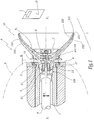
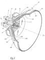
- the projector P represented at figure 1 is fed with coating material from one or more unrepresented sources and moved, for example with a substantially vertical movement represented by the double arrow F 1 , facing objects O to be coated within a facility I of coating of these objects.
- the projector comprises an air turbine of which only the rotor 1 is visible on the figure 1 , this rotor being rotated about an axis X 1 -X ' 1 .
- a body 2 fixed with respect to the axis X 1 -X ' 1 , surrounds the rotor 1 and is itself isolated from the outside by a cover 3.
- An annular support 4 made of magnetic material, for example stainless steel magnetic, is mounted on the front face 21 of the body 2, this support being provided with an annular groove centered on the axis X 1 -X ' 1 and in which is disposed an annular magnet 41.
- An injector 5 coating product is aligned on the axis X 1 -X ' 1 .
- a spraying member 10 is mounted on a projector P and forms a frustoconical surface 10A intended to cooperate with a frustoconical surface 1A of the rotor 1 to rotate the spraying member 10 and the rotor 1 in rotation.
- a ring 13 of ferromagnetic material is mounted on the spraying member 10, so that an attraction force F 2 due to the magnet 41 is exerted on the ring 13, which firmly plates the surfaces 10A and 1A against each other, while an air gap E is formed between the ring 13 and the support 4. It is made here application of the technical education of FR-A-2887472 .
- the spraying member 10 comprises two bowls 100 and 200, of different diameters and geometries.
- the outer bowl 100 is provided with a spray edge 101, a product distribution surface 102 and an outer surface 103.
- the injector 5 brings the liquid product to be sprayed to the bowl 100.
- the bowl 100 In the bowl 100 is fixed an internal bowl 200, by screwing, with a hub 6.
- the inner bowl 200 is immobilized on the hub 6 by any appropriate means, for example by gluing.
- the hub 6 is screwed, thanks to a thread 64, into a threaded portion 104 of the bowl 10.
- the two bowls 100 and 200 are thus assembled by being removable with respect to one another.
- a male centering cone is provided on the bowl 200, while a corresponding female centering cone is provided on the bowl 100. This ensures a permanent relative centering of these bowls.
- the bowl 200 can be fixed on the bowl 100 by other mechanical means, for example in force.
- the hub 6 is provided with pads 61 between which there are openings 62 here in the form of beans, for the passage of the coating product of the injector 5 to the inner surface 102 of the bowl 100.
- the bowl 200 is provided with a spray edge 201, a product distribution surface 202 and an outer surface 203.
- D 101 and D 201 denote respectively the diameters of the edges 101 and 201.
- the value of D 101 is slightly greater than that of D 201 . More precisely, D 101 is greater than X at Y% relative to D201.
- D 101 may be 63.5 mm, while D 201 is 65 mm.
- the distributor 7 is provided with pads 71 between which are formed openings 72, here in the form of beans, for the passage of the coating product to the inner surface 202 of the bowl 200.
- An insert 8 mounted in the bowl 200 defines an orifice 81 aligned on the central axis X 10 -X '10 of the member 10 which forms an axis of symmetry of the surfaces 102, 103, 202 and 203.
- the insert 8 protrudes from the rear face 206 of the bowl 200 intended to be turned towards the injector 5.
- the portion 82 of the insert 8, which protrudes with respect to the surface 206 has a convergent inner surface in direction of the ridge 201 and can be considered as a funnel.
- the portion 82 of the insert 8 projecting from the surface 206 may be in the form of "inverted funnel", with a diverging outer surface in the direction of the ridge 201 and a cylindrical inner surface with a circular base.
- the insert 8 may not protrude from the surface 206.
- the three forms of the insert 8 contemplated above make it possible to influence the distribution of the product between the flow paths formed by the surfaces 102 and 202 of the two bowls. Different types of bowls can therefore be provided, with inserts 8 of different geometry.
- edges 101 and 201 are not in the same plane, they are offset axially with respect to each other, the edge 101 being set back relative to the edge 201, in order to avoid as much as possible jets of pulverized product recombine, that is to say, mingle with each other.
- indented is meant that the edge 101 is further away from the objects O than the edge 201. It is necessary to separate as much as possible the jets of coating product from the edges 101 and 201. Indeed, if the These jets recombine, so the size of the droplets increases, while a uniform spray requires droplets as fine as possible.
- the distance d 1 of withdrawal of the edge 101 with respect to the edge 201 may be 10 millimeters for a bowl whose edge 201 has a diameter of the order of 65 mm.
- the distance d 1 represents more than 1% of the diameter D 201 of the edge 201, which ensures a good separation of the product jets without axially lengthening the bowl too much. The greater the shrinkage, the less jets of sprayed product recombine.
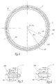
- the inner surface 102 of the bowl 100 and the outer surface 203 of the bowl 200 define a volume V 1 between them.
- the difference measured between the two bowls 100 and 200 is perpendicular to a median M between the generatrices of the surfaces 102 and 203, that is to say the thickness of the volume V 1 .
- the thickness e is equal to the distance between the inner surface 102 and the outer surface 203.
- the thickness ea for a given position along the axis X 10 -X '10 , the same value regardless of the angular sector around the axis X 10 -X' 10 in which it is measured, which is visible at the figure 4 where the thickness e is uniform.
- e 1 the value of the thickness e measured at the level of the entry zone of the product in the volume V 1 , at the height of the rear face 63 of the assembly consisting of the bowl 200, of the upper part of the hub. 6 and the distributor 8.
- e 2 the value of the thickness e measured at the edge 101 of the bowl 100.
- the thickness e decreases continuously from e 1 to e 2 , e 2 being less than e 1 .
- e 1 may be 2 mm while e 2 is a few tenths of a millimeter.
- the decrease of the value of e between the values e 1 and e 2 has the effect that the section S of product passage in the volume V 1 , which is annular as shown in FIG. figure 4 , has an area that decreases between the input area and the output area of this volume.
- the decrease in the value of the thickness e between the values e 1 and e 2 can take place non-continuously, this thickness being able, for example, to be constant over a part of the volume V 1 .
- the spraying member 10 rotates about the axis X 1 -X ' 1 .
- the two bowls 100 and 200 are integral and rotate at the same time, at the same speed.
- the coating product is fed through the injector 5, taps against the rear face 63 of the assembly consisting of the bowl 200, the upper part of the hub 6 and possibly the projecting portion 82 of the distributor 8, and spreads on the inner surface of the bowl 100, to the spraying edge 101 where the liquid splits into fine droplets.
- a fraction of the coating product supplied by the injector 5 continues its path directly into the distributor 8 through the orifice 81.
- This fraction is defined both by the geometry of the distributor 8, in particular the diameter inside of the orifice 81, and by the flow of coating product.
- This fraction taps against the rear face 73 of the distributor 7 and spreads on the inner surface of the bowl 200, to the spray edge 201 where the liquid splits into fine droplets.
- air-solvent trains are conveyed by the injector 5, sized with a flow rate for filling the volume V 1 .
- the air and solvent trains follow the same paths as the coating product, from the injector 5 to the edges 101 and 201.
- the reduction of the gap between the bowls 100 and 200 of e 1 to e 2 has the effect of compensating for a decrease in pressure due to the centrifugal force and of slightly compressing the rinsing liquid to allow the force-feeding of the volume V 1 during rinsing of the spray member, thereby rinsing the surface 102 and the surface 203 at the same time.
- the injection of cleaning product can properly clean not only the inner surfaces 102 and 202, but also the surface 203.
- the air-solvent trains can create a foam, by air dispersion in a liquid, which increases the cleaning efficiency. It is also possible that the cleaning product is itself a foaming product. In this case, the compression effect obtained due to the decrease in the thickness e is exerted on the air bubbles present in the dispersion or in the foaming product, which gives rise to a "scraping" effect of the bubbles. air on surfaces 102 and 203.
- the bowl 100 is pierced with a series of orifices 150 which each extend between an inlet 150A located on the surface 103 of the bowl 100 and an outlet 150B located on the surface 102.
- the orifices 150 are cylindrical, each centered on one axis X 150 oblique to the axis X 10 -X '10 .
- the orifices 150 make it possible to generate an air intake from the outside towards the volume V 1 . These holes are easy to achieve because they can be drilled in the bowl 100 before mounting the bowl 200.
- the invention has been shown with a spraying member 10 having two bowls. It is also applicable with a stack of three or more successive bowls connected in series ended by mounting a dispenser on the innermost bowl.
- volumes V 1 ,..., V n-1 may be defined by analogy with the embodiment shown, with different geometries, each volume having a decreasing radial thickness, from its zone of entry to its zone. Release.
- the invention has been shown with a spraying member 10 attached to the rotor 1 by magnetic effect. It is also applicable with a spraying member fixed by any other means, in particular screwed.
- the invention has been shown with bowls 100 and 200 removable. It is also applicable with an organ whose bowls are not removable, for example monoblocks.
- the invention has been represented with a bowl 100 whose edge 101 has a diameter D 101 greater than the diameter D 201 of the edge 201 of the bowl 200.
- the invention is however applicable to the case where the diameter D 101 is equal to slightly smaller than the diameter D 201 , which is possible because of the withdrawal d 1 of the edge 101 relative to the edge 201.
Landscapes
- Nozzles (AREA)
- Application Of Or Painting With Fluid Materials (AREA)
- Spray Control Apparatus (AREA)
- Cleaning By Liquid Or Steam (AREA)
Claims (11)
- Zerstäubungselement (10) für eine rotierende Sprühvorrichtung für Beschichtungsstoff, wobei das Zerstäubungselement (10) mindestens eine Außenschale (100) und eine Innenschale (200) umfasst, wobei jede Schale eine Zerstäubungskante (101, 201), eine Verteilungsinnenfläche (102, 202) und eine Außenfläche (103, 203) festlegt, wobei die Innenschale (200) radial im Inneren der Außenschale (100) angeordnet ist, wobei ein zwischen der Innenfläche (102) der Außenschale und der Außenfläche (203) der Innenschale definiertes Volumen (V1) eine Dicke (e) aufweist, die zwischen einem ersten Wert (e1), der an einer Eintrittszone von Reinigungsstoff in das Volumen (V1) genommen wird, und einem zweiten Wert (e2), der an der Zerstäubungskante (101) der Außenschale (100) genommen wird, fallend ist, wobei das Zerstäubungselement (10) dadurch gekennzeichnet ist, dass es Mittel (6, 8) zur zentralen Versorgung der Verteilungsinnenflächen (102, 202) der Schalen (100, 200) umfasst.
- Zerstäubungselement nach Anspruch 1, dadurch gekennzeichnet, dass die zentralen Versorgungsmittel einen Verteiler (8) umfassen, der mit einer auf eine Symmetrieachse (X10) der Innenflächen (102, 202) und Außenflächen (103, 203) der Schalen (100, 200) ausgerichtete Öffnung (81) versehen ist, wobei diese Öffnung für die Versorgung der Verteilungsinnenfläche (202) der Innenschale (200) mit Beschichtungsstoff vorgesehen ist.
- Zerstäubungselement nach einem der Ansprüche 1 oder 2, dadurch gekennzeichnet, dass die Versorgungsmittel ein Ablenkelement (7) umfassen, das in der Innenschale (200) gegenüberliegend zu einem zentralen Teil ihrer Verteilungsinnenfläche (202) montiert ist.
- Zerstäubungselement nach einem der vorhergehenden Ansprüche, dadurch gekennzeichnet, dass das Verhältnis (R) des zweiten Wertes (e2) zu dem ersten Wert (e1) kleiner als 0,9, vorzugsweise als 0,5, noch bevorzugter in der Größenordnung von 0,4 ist.
- Zerstäubungselement nach einem der vorhergehenden Ansprüche, dadurch gekennzeichnet, dass die Zerstäubungskante (101) der Außenschale axial in Bezug auf die Zerstäubungskante (201) der Innenschale (200) um eine Entfernung (d1) größer als 1% des Durchmessers (D201) der Zerstäubungskante (201) der Innenschale (200) zurückgesetzt ist.
- Zerstäubungselement nach einem der vorhergehenden Ansprüche, dadurch gekennzeichnet, dass die Außenschale (100) mit Öffnungen (150) für den Eintritt von Luft in das Volumen (V1) versehen ist, das zwischen der Außenfläche (203) der Innenschale (200) und der Innenfläche (102) der Außenschale festgelegt ist.
- Sprühvorrichtung für Beschichtungsstoff, ein Zerstäubungselement (10), Mittel (1) für den Antrieb des Elements zur Drehung und Mittel (5) zur Versorgung des Elements mit Beschichtungsstoff umfassend, dadurch gekennzeichnet, dass das Zerstäubungselement ein solches nach einem der vorhergehenden Ansprüche ist.
- Sprühvorrichtung nach Anspruch 7, bei der das Zerstäubungselement ein solches nach Anspruch 2 ist, dadurch gekennzeichnet, dass der Durchmesser (D81) der Öffnung (81) kleiner als der oder gleich dem Innendurchmesser (D51) des stromabwärts liegenden Endes (51) der Mittel (5) zur Versorgung mit Beschichtungsstoff ist.
- Sprühanlage für Beschichtungsprodukt, dadurch gekennzeichnet, dass sie mindestens eine Sprühvorrichtung nach einem der Ansprüche 7 oder 8 umfasst.
- Verfahren zum Reinigen eines Zerstäubungselements (10) nach einem der Ansprüche 1 bis 6, dadurch gekennzeichnet, dass es einen Schritt umfasst, der darin besteht, das Volumen (V1) mit Reinigungsstoff und/oder Luft zu überspülen.
- Verfahren nach Anspruch 10, dadurch gekennzeichnet, dass es darin besteht, für das Überspülen des Volumens (V1) einen Reinigungsstoff oder eine Mischung aus Reinigungsstoff und sprudelnder Luft zu verwenden.
Priority Applications (1)
| Application Number | Priority Date | Filing Date | Title |
|---|---|---|---|
| PL08805488T PL2139604T3 (pl) | 2007-04-23 | 2008-04-22 | Człon rozpylający, urządzenie natryskujące zawierające taki człon, instalacja do natryskiwania i sposób czyszczenia takiego członu |
Applications Claiming Priority (2)
| Application Number | Priority Date | Filing Date | Title |
|---|---|---|---|
| FR0702929A FR2915115B1 (fr) | 2007-04-23 | 2007-04-23 | Organe de pulverisation,dispositif de projection comportant un tel organe,installation de projection et methode de nettoyage d'un tel organe |
| PCT/FR2008/000568 WO2008145846A2 (fr) | 2007-04-23 | 2008-04-22 | Organe de pulverisation, dispositif de projection comportant un tel organe, installation de projection et methode de nettoyage d'un tel organe |
Publications (2)
| Publication Number | Publication Date |
|---|---|
| EP2139604A2 EP2139604A2 (de) | 2010-01-06 |
| EP2139604B1 true EP2139604B1 (de) | 2017-07-26 |
Family
ID=38752538
Family Applications (1)
| Application Number | Title | Priority Date | Filing Date |
|---|---|---|---|
| EP08805488.7A Active EP2139604B1 (de) | 2007-04-23 | 2008-04-22 | Sprühelement, sprühvorrichtung mit einem solchen element, sprühanlage und verfahren zur reinigung eines solchen elements |
Country Status (6)
| Country | Link |
|---|---|
| US (1) | US8905325B2 (de) |
| EP (1) | EP2139604B1 (de) |
| ES (1) | ES2644755T3 (de) |
| FR (1) | FR2915115B1 (de) |
| PL (1) | PL2139604T3 (de) |
| WO (1) | WO2008145846A2 (de) |
Families Citing this family (18)
| Publication number | Priority date | Publication date | Assignee | Title |
|---|---|---|---|---|
| DE102009037604A1 (de) * | 2009-08-14 | 2011-02-24 | Dürr Systems GmbH | Farbdüse für einen Glockenteller eines Rotationszerstäubers |
| TW201302793A (zh) | 2010-09-03 | 2013-01-16 | Glaxo Group Ltd | 新穎之抗原結合蛋白 |
| US9488108B2 (en) * | 2012-10-17 | 2016-11-08 | Delavan Inc. | Radial vane inner air swirlers |
| EP2808087B1 (de) * | 2013-05-28 | 2019-02-27 | Valmet Technologies, Inc. | Vorrichtung zur Behandlung eines Fasernetzes |
| WO2015114924A1 (ja) * | 2014-01-29 | 2015-08-06 | 本田技研工業株式会社 | 回転霧化式塗装装置及び噴霧ヘッド |
| KR101634298B1 (ko) * | 2016-01-20 | 2016-06-30 | 박상은 | 더블 벨컵 |
| GB2563054B (en) * | 2017-06-01 | 2022-04-20 | Novanta Tech Uk Limited | Rotary atomiser bell cups |
| US20200041130A1 (en) | 2018-07-31 | 2020-02-06 | Hotstart, Inc. | Combustor Systems |
| USD910717S1 (en) | 2018-07-31 | 2021-02-16 | Hotstart, Inc. | Rotary atomizer |
| FR3087680B1 (fr) * | 2018-10-30 | 2023-02-10 | Exel Ind | Bol de pulverisation de produit de revetement, projecteur rotatif incluant un tel bol et procede de nettoyage d'un tel projecteur |
| DE102018129964B4 (de) * | 2018-11-27 | 2023-11-16 | Dürr Systems Ag | Rotationszerstäuber und dessen Betriebsverfahren sowie Beschichtungsroboter mit Rotationszerstäuber |
| CN109526730B (zh) * | 2018-12-21 | 2022-02-08 | 曹哲峰 | 一种西红柿专用人工授粉装置及方法 |
| CN113950378A (zh) | 2019-06-10 | 2022-01-18 | 阿特拉斯·科普柯空气动力股份有限公司 | 对压缩机或真空泵壳体进行涂装的涂装装置和所用方法 |
| BE1027347B1 (nl) | 2019-06-10 | 2021-01-19 | Atlas Copco Airpower Nv | Inrichting voor het schilderen van een behuizing van een compressor- of vacuümpompelement en toegepaste werkwijze |
| CN110624736B (zh) * | 2019-09-25 | 2021-08-20 | 宝应县润华静电涂装工程有限公司 | 一种环保干式循环喷漆房 |
| JP7220730B2 (ja) * | 2021-01-15 | 2023-02-10 | 本田技研工業株式会社 | 回転霧化式塗装装置 |
| JP6948487B1 (ja) * | 2021-06-23 | 2021-10-13 | アーベーベー・シュバイツ・アーゲーABB Schweiz AG | 静電塗装装置 |
| DE102021127163A1 (de) * | 2021-10-20 | 2023-04-20 | Dürr Systems Ag | Glockenteller und Rotationszerstäuber mit einem solchen Glockenteller |
Family Cites Families (31)
| Publication number | Priority date | Publication date | Assignee | Title |
|---|---|---|---|---|
| US3009441A (en) * | 1959-06-18 | 1961-11-21 | Ransburg Electro Coating Corp | Apparatus for electrostatically spray coating |
| NL277060A (de) * | 1961-04-14 | |||
| FR1363681A (fr) | 1962-07-17 | 1964-06-12 | Installation pour déposer par voie électrostatique une matière fluide de recouvrement sur un objet | |
| GB1053514A (de) * | 1963-02-19 | 1900-01-01 | ||
| DE1577637C3 (de) * | 1964-08-26 | 1973-11-15 | Robert Bosch Hausgeraete Gmbh, 7927 Giengen | Vorrichtung zum Aufsprühen von flussigen Auftragsmitteln, insbesonde re von Lacken |
| DE1577654A1 (de) * | 1966-10-04 | 1970-01-29 | Bosch Hausgeraete Gmbh | Vorrichtung zum Aufspruehen von fluessigen Auftragsmitteln |
| AT279775B (de) * | 1967-06-15 | 1970-03-25 | Villamos Automatika Intezet | Vorrichtung zum gleichzeitigen elektrostatischen Spritzen verschiedener Stoffe |
| FR2170940A1 (de) * | 1972-02-09 | 1973-09-21 | Usimat Sa | |
| SU733565A1 (ru) * | 1978-11-02 | 1980-05-18 | Всесоюзный Ордена Трудового Красного Знамени Научно-Исследовательский Институт Сельскохозяйственного Машиностроения Им. В.П.Горячкина | Распылитель жидкости |
| US4555058A (en) * | 1983-10-05 | 1985-11-26 | Champion Spark Plug Company | Rotary atomizer coater |
| US4785995A (en) * | 1986-03-18 | 1988-11-22 | Mazda Motor Corporation | Methods and apparatus for conducting electrostatic spray coating |
| DE8708312U1 (de) * | 1987-06-12 | 1987-07-30 | Behr Industrieanlagen GmbH & Co, 74379 Ingersheim | Einrichtung zum Vernebeln flüssiger Farbe |
| FR2652518B1 (fr) * | 1989-10-03 | 1994-04-08 | Sames Sa | Dispositif de projection de produit de revetement a organe rotatif de pulverisation. |
| US5474236A (en) * | 1992-12-03 | 1995-12-12 | Nordson Corporation | Transfer of electrostatic charge to a rotary atomizer head through the housing of a rotary atomizing spray device |
| DE4340441A1 (de) * | 1992-12-03 | 1994-06-09 | Nordson Corp | Rotationszerstäuber |
| JP3753462B2 (ja) * | 1995-01-10 | 2006-03-08 | マツダ株式会社 | 多色回転霧化塗装装置および洗浄方法 |
| US5632448A (en) * | 1995-01-25 | 1997-05-27 | Ransburg Corporation | Rotary powder applicator |
| JP3726329B2 (ja) * | 1996-02-16 | 2005-12-14 | トヨタ自動車株式会社 | 回転霧化静電塗装機のベルヘッドおよび回転霧化静電塗装機 |
| DE69717416T2 (de) * | 1996-10-01 | 2003-04-03 | Alstom Power K.K., Kobe | Rotationszerstäubungskopf |
| EP0878238B1 (de) * | 1996-12-03 | 2009-03-11 | Abb K.K. | Beschichtungsvorrichtung mit einem rotierenden sprühkopf |
| US6328224B1 (en) * | 1997-02-05 | 2001-12-11 | Illinois Tool Works Inc. | Replaceable liner for powder coating apparatus |
| US5853126A (en) * | 1997-02-05 | 1998-12-29 | Illinois Tool Works, Inc. | Quick disconnect for powder coating apparatus |
| US5947377A (en) * | 1997-07-11 | 1999-09-07 | Nordson Corporation | Electrostatic rotary atomizing spray device with improved atomizer cup |
| FR2791279B1 (fr) * | 1999-03-25 | 2002-03-29 | Sames Sa | Dispositif de projection d'un produit de revetement en poudre et organe de projection equipant un tel dispositif |
| US6341734B1 (en) * | 2000-10-19 | 2002-01-29 | Efc Systems, Inc. | Rotary atomizer and bell cup and methods thereof |
| KR100473034B1 (ko) * | 2000-12-20 | 2005-03-10 | 에이비비 가부시키가이샤 | 회전무화헤드형 도장장치 |
| US7128277B2 (en) * | 2003-07-29 | 2006-10-31 | Illinois Tool Works Inc. | Powder bell with secondary charging electrode |
| JP4428973B2 (ja) * | 2003-09-10 | 2010-03-10 | トヨタ自動車株式会社 | 回転霧化塗装装置および塗装方法 |
| DE602005005635T2 (de) * | 2004-02-06 | 2009-05-14 | Sames Technologies | Sprühglocke für einen rotationszerstäuber mit magnetischer befestigung |
| JP4606065B2 (ja) * | 2004-05-24 | 2011-01-05 | トリニティ工業株式会社 | 塗装機とその回転霧化頭 |
| FR2887472B1 (fr) | 2005-06-23 | 2007-09-28 | Sames Technologies Soc Par Act | Bol de pulverisation, dispositif de projection equipe d'un tel bol, installation comprenant un tel dispositif et procede de montage d'un tel bol |
-
2007
- 2007-04-23 FR FR0702929A patent/FR2915115B1/fr active Active
-
2008
- 2008-04-22 WO PCT/FR2008/000568 patent/WO2008145846A2/fr not_active Ceased
- 2008-04-22 PL PL08805488T patent/PL2139604T3/pl unknown
- 2008-04-22 US US12/597,330 patent/US8905325B2/en active Active
- 2008-04-22 EP EP08805488.7A patent/EP2139604B1/de active Active
- 2008-04-22 ES ES08805488.7T patent/ES2644755T3/es active Active
Non-Patent Citations (1)
| Title |
|---|
| None * |
Also Published As
| Publication number | Publication date |
|---|---|
| US20100193602A1 (en) | 2010-08-05 |
| WO2008145846A2 (fr) | 2008-12-04 |
| PL2139604T3 (pl) | 2018-01-31 |
| US8905325B2 (en) | 2014-12-09 |
| WO2008145846A3 (fr) | 2009-03-12 |
| FR2915115B1 (fr) | 2010-09-10 |
| FR2915115A1 (fr) | 2008-10-24 |
| EP2139604A2 (de) | 2010-01-06 |
| ES2644755T3 (es) | 2017-11-30 |
Similar Documents
| Publication | Publication Date | Title |
|---|---|---|
| EP2139604B1 (de) | Sprühelement, sprühvorrichtung mit einem solchen element, sprühanlage und verfahren zur reinigung eines solchen elements | |
| EP2429716B1 (de) | Sprüheinrichtung und glied zum spritzen eines beschichtungsmaterials und solch ein spritzverfahren verwendende spritzvorrichtung | |
| EP3231516B1 (de) | Spritzdüse, insbesondere für ein system zur verteilung eines unter druck stehenden produkts, das mit einem druckknopf ausgestattet ist, und verteilungssystem, das eine solche düse umfasst | |
| FR2586206A1 (fr) | Tete d'atomiseur centrifuge et cet atomiseur | |
| EP3296022B1 (de) | Beschichtungseinrichtung | |
| EP1963023B1 (de) | Vorrichtung zum sprühen einer flüssigkeit | |
| EP1007220A1 (de) | Vernebelungskopf- und vorrichtung | |
| EP1305118B2 (de) | Vorrichtung zum speisen eines spritzgeräts mit einem pulverlack und sprühbeschichtungsanlage mit einer solchen vorrichtung | |
| EP2361157B1 (de) | Beschichtungsmittelsprühkopf | |
| EP3873677B1 (de) | Behälter zum sprühen eines beschichtungsproduktes, rotationssprühvorrichtung mit einer solchen schale und verfahren zum reinigen einer solchen sprühvorrichtung | |
| WO2015022328A1 (fr) | Pulverisateur d'un produit de revetement liquide et installation de pulverisation comprenant un tel pulverisateur | |
| WO2008145845A1 (fr) | Organe de pulverisation, dispositif de projection comportant un tel organe et installation de projection comprenant un tel dispositif | |
| FR2501075A1 (fr) | Coupelle rotative d'atomisation pour applicateur de peinture liquide et procede d'application de peinture liquide | |
| EP1545792B1 (de) | Sprühglocke, austragsvorrichtung mit solch einer glocke und eine solche vorrichtung umfassende austragsanlage | |
| WO2021156573A1 (fr) | Buse de pulvérisation de liquide sous forme de brouillard | |
| EP1883478B1 (de) | Düse mit einer wirbelkammer | |
| EP2836309B1 (de) | Rotierender zerstäuber und verfahren zum sprühen von beschichtungsmitteln | |
| EP0897324A1 (de) | Zweiphasen-sprühvorrichtung zum sprühen eines flüssigen oder pastösen mediums | |
| EP3530355B1 (de) | Ausgabekopf mit einer abgestuften wirbelkammer für ein ausgabesystem | |
| EP4656296A1 (de) | Sprühglockenteller für flüssiges beschichtungsprodukt, rotationszerstäuber mit solch einem glockenteller und verfahren zum auftragen eines beschichtungsprodukts mit solch einem rotationszerstäuber | |
| EP3749444B1 (de) | Vorrichtung zur injektion eines ausgangsstoffes einer fcc-einheit mit lokal grösserem querschnitt | |
| FR2852868A1 (fr) | Bol de pulverisation, dispositif de projection incorporant un tel bol et installation de projection incorporant un tel dispositif | |
| BE1028008A1 (fr) | Atomiseur pour la pulverisation d'un liquide | |
| WO2010149881A1 (fr) | Procédé de fabrication et de contrôle d'un injecteur de brumisation |
Legal Events
| Date | Code | Title | Description |
|---|---|---|---|
| PUAI | Public reference made under article 153(3) epc to a published international application that has entered the european phase |
Free format text: ORIGINAL CODE: 0009012 |
|
| 17P | Request for examination filed |
Effective date: 20091027 |
|
| AK | Designated contracting states |
Kind code of ref document: A2 Designated state(s): AT BE BG CH CY CZ DE DK EE ES FI FR GB GR HR HU IE IS IT LI LT LU LV MC MT NL NO PL PT RO SE SI SK TR |
|
| RIN1 | Information on inventor provided before grant (corrected) |
Inventor name: PERINET, SYLVAIN Inventor name: BALLU, PATRICK |
|
| DAX | Request for extension of the european patent (deleted) | ||
| GRAP | Despatch of communication of intention to grant a patent |
Free format text: ORIGINAL CODE: EPIDOSNIGR1 |
|
| INTG | Intention to grant announced |
Effective date: 20170224 |
|
| RAP1 | Party data changed (applicant data changed or rights of an application transferred) |
Owner name: SAMES KREMLIN |
|
| GRAS | Grant fee paid |
Free format text: ORIGINAL CODE: EPIDOSNIGR3 |
|
| GRAA | (expected) grant |
Free format text: ORIGINAL CODE: 0009210 |
|
| AK | Designated contracting states |
Kind code of ref document: B1 Designated state(s): AT BE BG CH CY CZ DE DK EE ES FI FR GB GR HR HU IE IS IT LI LT LU LV MC MT NL NO PL PT RO SE SI SK TR |
|
| REG | Reference to a national code |
Ref country code: GB Ref legal event code: FG4D Free format text: NOT ENGLISH |
|
| REG | Reference to a national code |
Ref country code: CH Ref legal event code: EP |
|
| REG | Reference to a national code |
Ref country code: AT Ref legal event code: REF Ref document number: 911952 Country of ref document: AT Kind code of ref document: T Effective date: 20170815 |
|
| REG | Reference to a national code |
Ref country code: IE Ref legal event code: FG4D Free format text: LANGUAGE OF EP DOCUMENT: FRENCH |
|
| REG | Reference to a national code |
Ref country code: DE Ref legal event code: R096 Ref document number: 602008051321 Country of ref document: DE |
|
| REG | Reference to a national code |
Ref country code: NL Ref legal event code: MP Effective date: 20170726 |
|
| REG | Reference to a national code |
Ref country code: ES Ref legal event code: FG2A Ref document number: 2644755 Country of ref document: ES Kind code of ref document: T3 Effective date: 20171130 |
|
| REG | Reference to a national code |
Ref country code: LT Ref legal event code: MG4D |
|
| REG | Reference to a national code |
Ref country code: AT Ref legal event code: MK05 Ref document number: 911952 Country of ref document: AT Kind code of ref document: T Effective date: 20170726 |
|
| PG25 | Lapsed in a contracting state [announced via postgrant information from national office to epo] |
Ref country code: AT Free format text: LAPSE BECAUSE OF FAILURE TO SUBMIT A TRANSLATION OF THE DESCRIPTION OR TO PAY THE FEE WITHIN THE PRESCRIBED TIME-LIMIT Effective date: 20170726 Ref country code: NL Free format text: LAPSE BECAUSE OF FAILURE TO SUBMIT A TRANSLATION OF THE DESCRIPTION OR TO PAY THE FEE WITHIN THE PRESCRIBED TIME-LIMIT Effective date: 20170726 Ref country code: HR Free format text: LAPSE BECAUSE OF FAILURE TO SUBMIT A TRANSLATION OF THE DESCRIPTION OR TO PAY THE FEE WITHIN THE PRESCRIBED TIME-LIMIT Effective date: 20170726 Ref country code: LT Free format text: LAPSE BECAUSE OF FAILURE TO SUBMIT A TRANSLATION OF THE DESCRIPTION OR TO PAY THE FEE WITHIN THE PRESCRIBED TIME-LIMIT Effective date: 20170726 Ref country code: NO Free format text: LAPSE BECAUSE OF FAILURE TO SUBMIT A TRANSLATION OF THE DESCRIPTION OR TO PAY THE FEE WITHIN THE PRESCRIBED TIME-LIMIT Effective date: 20171026 Ref country code: FI Free format text: LAPSE BECAUSE OF FAILURE TO SUBMIT A TRANSLATION OF THE DESCRIPTION OR TO PAY THE FEE WITHIN THE PRESCRIBED TIME-LIMIT Effective date: 20170726 Ref country code: SE Free format text: LAPSE BECAUSE OF FAILURE TO SUBMIT A TRANSLATION OF THE DESCRIPTION OR TO PAY THE FEE WITHIN THE PRESCRIBED TIME-LIMIT Effective date: 20170726 |
|
| PG25 | Lapsed in a contracting state [announced via postgrant information from national office to epo] |
Ref country code: LV Free format text: LAPSE BECAUSE OF FAILURE TO SUBMIT A TRANSLATION OF THE DESCRIPTION OR TO PAY THE FEE WITHIN THE PRESCRIBED TIME-LIMIT Effective date: 20170726 Ref country code: GR Free format text: LAPSE BECAUSE OF FAILURE TO SUBMIT A TRANSLATION OF THE DESCRIPTION OR TO PAY THE FEE WITHIN THE PRESCRIBED TIME-LIMIT Effective date: 20171027 Ref country code: IS Free format text: LAPSE BECAUSE OF FAILURE TO SUBMIT A TRANSLATION OF THE DESCRIPTION OR TO PAY THE FEE WITHIN THE PRESCRIBED TIME-LIMIT Effective date: 20171126 Ref country code: BG Free format text: LAPSE BECAUSE OF FAILURE TO SUBMIT A TRANSLATION OF THE DESCRIPTION OR TO PAY THE FEE WITHIN THE PRESCRIBED TIME-LIMIT Effective date: 20171026 |
|
| REG | Reference to a national code |
Ref country code: FR Ref legal event code: PLFP Year of fee payment: 11 |
|
| PG25 | Lapsed in a contracting state [announced via postgrant information from national office to epo] |
Ref country code: DK Free format text: LAPSE BECAUSE OF FAILURE TO SUBMIT A TRANSLATION OF THE DESCRIPTION OR TO PAY THE FEE WITHIN THE PRESCRIBED TIME-LIMIT Effective date: 20170726 Ref country code: CZ Free format text: LAPSE BECAUSE OF FAILURE TO SUBMIT A TRANSLATION OF THE DESCRIPTION OR TO PAY THE FEE WITHIN THE PRESCRIBED TIME-LIMIT Effective date: 20170726 Ref country code: RO Free format text: LAPSE BECAUSE OF FAILURE TO SUBMIT A TRANSLATION OF THE DESCRIPTION OR TO PAY THE FEE WITHIN THE PRESCRIBED TIME-LIMIT Effective date: 20170726 |
|
| REG | Reference to a national code |
Ref country code: DE Ref legal event code: R097 Ref document number: 602008051321 Country of ref document: DE |
|
| PG25 | Lapsed in a contracting state [announced via postgrant information from national office to epo] |
Ref country code: SK Free format text: LAPSE BECAUSE OF FAILURE TO SUBMIT A TRANSLATION OF THE DESCRIPTION OR TO PAY THE FEE WITHIN THE PRESCRIBED TIME-LIMIT Effective date: 20170726 Ref country code: EE Free format text: LAPSE BECAUSE OF FAILURE TO SUBMIT A TRANSLATION OF THE DESCRIPTION OR TO PAY THE FEE WITHIN THE PRESCRIBED TIME-LIMIT Effective date: 20170726 |
|
| PLBE | No opposition filed within time limit |
Free format text: ORIGINAL CODE: 0009261 |
|
| STAA | Information on the status of an ep patent application or granted ep patent |
Free format text: STATUS: NO OPPOSITION FILED WITHIN TIME LIMIT |
|
| 26N | No opposition filed |
Effective date: 20180430 |
|
| PG25 | Lapsed in a contracting state [announced via postgrant information from national office to epo] |
Ref country code: SI Free format text: LAPSE BECAUSE OF FAILURE TO SUBMIT A TRANSLATION OF THE DESCRIPTION OR TO PAY THE FEE WITHIN THE PRESCRIBED TIME-LIMIT Effective date: 20170726 |
|
| PG25 | Lapsed in a contracting state [announced via postgrant information from national office to epo] |
Ref country code: MT Free format text: LAPSE BECAUSE OF FAILURE TO SUBMIT A TRANSLATION OF THE DESCRIPTION OR TO PAY THE FEE WITHIN THE PRESCRIBED TIME-LIMIT Effective date: 20170726 |
|
| PG25 | Lapsed in a contracting state [announced via postgrant information from national office to epo] |
Ref country code: MC Free format text: LAPSE BECAUSE OF FAILURE TO SUBMIT A TRANSLATION OF THE DESCRIPTION OR TO PAY THE FEE WITHIN THE PRESCRIBED TIME-LIMIT Effective date: 20170726 |
|
| REG | Reference to a national code |
Ref country code: CH Ref legal event code: PL |
|
| REG | Reference to a national code |
Ref country code: BE Ref legal event code: MM Effective date: 20180430 |
|
| REG | Reference to a national code |
Ref country code: IE Ref legal event code: MM4A |
|
| PG25 | Lapsed in a contracting state [announced via postgrant information from national office to epo] |
Ref country code: LU Free format text: LAPSE BECAUSE OF NON-PAYMENT OF DUE FEES Effective date: 20180422 |
|
| PG25 | Lapsed in a contracting state [announced via postgrant information from national office to epo] |
Ref country code: BE Free format text: LAPSE BECAUSE OF NON-PAYMENT OF DUE FEES Effective date: 20180430 Ref country code: CH Free format text: LAPSE BECAUSE OF NON-PAYMENT OF DUE FEES Effective date: 20180430 Ref country code: LI Free format text: LAPSE BECAUSE OF NON-PAYMENT OF DUE FEES Effective date: 20180430 |
|
| PG25 | Lapsed in a contracting state [announced via postgrant information from national office to epo] |
Ref country code: IE Free format text: LAPSE BECAUSE OF NON-PAYMENT OF DUE FEES Effective date: 20180422 |
|
| PG25 | Lapsed in a contracting state [announced via postgrant information from national office to epo] |
Ref country code: TR Free format text: LAPSE BECAUSE OF FAILURE TO SUBMIT A TRANSLATION OF THE DESCRIPTION OR TO PAY THE FEE WITHIN THE PRESCRIBED TIME-LIMIT Effective date: 20170726 |
|
| PGFP | Annual fee paid to national office [announced via postgrant information from national office to epo] |
Ref country code: PL Payment date: 20200326 Year of fee payment: 13 |
|
| PG25 | Lapsed in a contracting state [announced via postgrant information from national office to epo] |
Ref country code: PT Free format text: LAPSE BECAUSE OF FAILURE TO SUBMIT A TRANSLATION OF THE DESCRIPTION OR TO PAY THE FEE WITHIN THE PRESCRIBED TIME-LIMIT Effective date: 20170726 Ref country code: HU Free format text: LAPSE BECAUSE OF FAILURE TO SUBMIT A TRANSLATION OF THE DESCRIPTION OR TO PAY THE FEE WITHIN THE PRESCRIBED TIME-LIMIT; INVALID AB INITIO Effective date: 20080422 |
|
| PG25 | Lapsed in a contracting state [announced via postgrant information from national office to epo] |
Ref country code: CY Free format text: LAPSE BECAUSE OF FAILURE TO SUBMIT A TRANSLATION OF THE DESCRIPTION OR TO PAY THE FEE WITHIN THE PRESCRIBED TIME-LIMIT Effective date: 20170726 |
|
| PGFP | Annual fee paid to national office [announced via postgrant information from national office to epo] |
Ref country code: ES Payment date: 20200518 Year of fee payment: 13 |
|
| PGFP | Annual fee paid to national office [announced via postgrant information from national office to epo] |
Ref country code: GB Payment date: 20200427 Year of fee payment: 13 Ref country code: IT Payment date: 20200415 Year of fee payment: 13 |
|
| GBPC | Gb: european patent ceased through non-payment of renewal fee |
Effective date: 20210422 |
|
| PG25 | Lapsed in a contracting state [announced via postgrant information from national office to epo] |
Ref country code: GB Free format text: LAPSE BECAUSE OF NON-PAYMENT OF DUE FEES Effective date: 20210422 |
|
| REG | Reference to a national code |
Ref country code: ES Ref legal event code: FD2A Effective date: 20220705 |
|
| PG25 | Lapsed in a contracting state [announced via postgrant information from national office to epo] |
Ref country code: ES Free format text: LAPSE BECAUSE OF NON-PAYMENT OF DUE FEES Effective date: 20210423 |
|
| PG25 | Lapsed in a contracting state [announced via postgrant information from national office to epo] |
Ref country code: PL Free format text: LAPSE BECAUSE OF NON-PAYMENT OF DUE FEES Effective date: 20210422 |
|
| PG25 | Lapsed in a contracting state [announced via postgrant information from national office to epo] |
Ref country code: IT Free format text: LAPSE BECAUSE OF NON-PAYMENT OF DUE FEES Effective date: 20200422 |
|
| PGFP | Annual fee paid to national office [announced via postgrant information from national office to epo] |
Ref country code: DE Payment date: 20250411 Year of fee payment: 18 |
|
| PGFP | Annual fee paid to national office [announced via postgrant information from national office to epo] |
Ref country code: FR Payment date: 20250429 Year of fee payment: 18 |
|
| PG25 | Lapsed in a contracting state [announced via postgrant information from national office to epo] |
Ref country code: IT Free format text: LAPSE BECAUSE OF NON-PAYMENT OF DUE FEES Effective date: 20210422 |