EP2128529B1 - Ofenmuffel - Google Patents
Ofenmuffel Download PDFInfo
- Publication number
- EP2128529B1 EP2128529B1 EP09005032.9A EP09005032A EP2128529B1 EP 2128529 B1 EP2128529 B1 EP 2128529B1 EP 09005032 A EP09005032 A EP 09005032A EP 2128529 B1 EP2128529 B1 EP 2128529B1
- Authority
- EP
- European Patent Office
- Prior art keywords
- oven muffle
- wall
- molded
- wall elements
- oven
- Prior art date
- Legal status (The legal status is an assumption and is not a legal conclusion. Google has not performed a legal analysis and makes no representation as to the accuracy of the status listed.)
- Not-in-force
Links
Images



Classifications
-
- F—MECHANICAL ENGINEERING; LIGHTING; HEATING; WEAPONS; BLASTING
- F24—HEATING; RANGES; VENTILATING
- F24C—DOMESTIC STOVES OR RANGES ; DETAILS OF DOMESTIC STOVES OR RANGES, OF GENERAL APPLICATION
- F24C15/00—Details
- F24C15/08—Foundations or supports plates; Legs or pillars; Casings; Wheels
Definitions
- the invention relates to a furnace muffle, in particular baking oven muffle with at least two adjoining wall elements, which delimit at least partially an interior serving in particular as a cooking space, wherein the wall elements made of glass or glass ceramic, and wherein the adjacent wall elements are at an angle to each other and wherein the wall elements (11 , 12, 50) are integrally connected to one another and form a shaped part (10),
- the oven consists essentially of an enamelled oven muffle, which is heated at the top and bottom with tubular heaters. On the front, the oven muffle is closed with a framed glass door.
- the upper heating is arranged in the interior of the baking oven muffle and is supported in high-quality ovens by a second radiator, which allows a grill function of the oven.
- the lower radiator is applied to the outside of the muffle floor.
- a circulating air blower used which may also have a separate heating ring, not only to circulate air, but also to produce hot air itself.
- oven walls made of glass or glass ceramic.
- the use of glass ceramic in ovens is already in the CA 2,183,498 described.
- the oven is proposed for better cleanability of glass ceramic.
- an oven muffle glass ceramic is described, which is detachably joined together and is heated by mounted externally radiant heater.
- the discs are inserted into a supporting or holding frame, by the resulting edges and joints, especially in the lower corners of the oven muffle this is very bad to clean.
- the design effort is high.
- the bill is in the DE 35 27 958 C2 proposed an enameled sheet steel muffle, wherein in the side walls window openings are provided, are used in the glass or glass ceramic panes. In this case, there is the same problem with the joints and joints which are difficult to clean and, in addition, a large part of the muffle space is still formed from enamelled sheet steel.
- the wall elements of the oven muffle are integrally connected to each other and form a molded part. According to the invention the wall elements are angled against each other. This results in the transition region of the two wall elements facing the interior a closed contour that is easy to clean.
- the one-piece connection of the wall elements of glass or glass ceramic creates a mechanical bond that is statically sufficiently stable. It can be dispensed with in favor of a simple construction so that on a support frame.
- the oven muffle according to the invention is such that in the region of the joint of two juxtaposed molded parts or in the region of the joint of a molded part with a plate-like wall element, a support member is held. As a result, the functionality can be increased with little effort.
- the support member can then serve either inside or outside to connect attachments. It is conceivable that in the interior of a support frame is attached (for example, for baking trays, roasters, etc.). On the outside, the support member may for example have brackets for suspending the oven muffle in the stove.
- the molded part has three wall elements, and that the wall elements are arranged such that the molded part is substantially V- or U-shaped. If the design of the oven muffel provides that from the wall element formed as a bottom or top wall on opposite wall elements, the two wall elements formed as side walls are bent, then all edge regions of the oven muffle, in which dirt accumulates increasingly, are easily cleaned.
- a conceivable alternative of the invention provides that the boundary edges of the mutually bent wall elements which face the oven muffle front and / or rear side merge into one another to form a planar sealing surface. At the Ofenmuffel front then manages the stop and the sealing of the oven door in a simple way. On the back, a further wall element can be applied sealed on the molding, which limits the back of the interior.
- At least one of the wall elements on its side facing away from the other, molded-on wall element forms a flat sealing surface. Then can be attached to the side of the wall elements in addition wall elements or other molded parts sealed in a simple manner.
- the functionality of the molded part can be additionally improved if it is provided that at least one of the wall elements at least one integrally molded functional element (projection, receptacle, recess), which is formed in the inner surface facing the interior of the wall element or in the interior of the inner surface protrudes.
- at least one of the wall elements at least one integrally molded functional element (projection, receptacle, recess), which is formed in the inner surface facing the interior of the wall element or in the interior of the inner surface protrudes.
- a furnace muffle be, for example, such that the functional element in the region of the front and / or back of the furnace muffle to the furnace muffle bottom and / or on the furnace muffle side walls forming wall elements or is formed.
- the functional element can then be used as a barrier or leakage protection for grease.
- the functional elements in the form of shots in at least one of the furnace muffle side walls forming wall elements or molded are. Then the functional elements can assume a supporting function here.
- a preferred embodiment of the oven muffle is characterized in that at the two, the furnace muffle side walls forming wall elements receptacles are arranged, which form in the direction of the oven muffle depth guides for baking trays. Again, the idea of simple cleanability is consistently taken into account.
- the functional element can also be molded in the form of a grease trap as a recess in the oven muffle bottom.
- the interior of at least two mold parts is limited.
- the moldings can then be assembled to limit the interior at least partially.
- the shaped parts form the oven-muffle bottom, the two oven muffle side walls and the oven muffle lid in the manner of a frame. This results in a stable construction.
- At least one plate-like wall element is held on the molding, which limits the Innraum and that the molding and the at least one plate-like wall element frame-like the Ofenmuffelboden, the two Ofenmuffel discharge subject and the Ofenmuffeldeckel.
- a stable fixation of the dressing succeeds in a simple manner in that the shaped parts or the shaped part and the plate-like wall element are braced against one another by means of strapping elements.
- the strapping element is at least partially resilient or has a spring element.
- the strapping element has holding elements. Then, for example, heating elements can be attached to the strapping element.
- the holding elements can also be used to suspend the oven muffle in the stove.
- the support member may also have a luminous element for illuminating the interior.
- a temperature-resistant luminous element can be used in particular also optical fibers, which couple their light in the edge of the wall element in the region of the joint.
- the Fig. 1 shows a sheet-like rectangular blank 10.1 made of glass or glass ceramic, which is suspended from a glass / glass ceramic tape. On the top of the blank 10.1 a continuous projection 17 is profiled, which is formed during rolling, the glass ribbon from the melt.
- dashed lines of bends 18.1 are indicated, which extend in the width direction of the blank 10.1.
- At these bending lines 18.1 of the blank 10.1 to the in Fig. 2 formed molding 10 formed.
- two vertical lateral wall elements 11 are bent in a U-shape by a horizontal wall element 12 on the bending lines 18.1 to form rounded bending edges 18. It is also conceivable that the wall elements 11 are employed at an angle greater than 90 ° to the wall element 12 V-shaped.
- the projection 17 forms in the region of the front of the oven muffle an overflow barrier on the oven (wall element 12), which prevents leakage of, for example, fat.
- the inner surfaces 13 of the wall elements 11 and 12 are rounded in favor of a good cleanability in the coupling areas into each other.
- the front and back edges of the wall elements 11 and 12 are flush with each other, so that there are flat sealing surfaces 19.1 and 19.3.
- an oven door (not shown) and at the back another wall element (not shown) can be struck sealed.
- the free ends of the wall elements 11 form horizontal sealing surfaces 19.2.
- Fig. 2 and 3 is a blank 10.1 or a molding 10 for a furnace muffle described in their design of the blank 10.1 and the molding 10 according to Fig. 1 and 2 correspond.
- the only difference is the formation of a second projection 17. This is arranged in the back Ofenmuffel Symposium. Between the two bottom projections 17 and the respective wall elements 11 thus a spatially limited collection is formed.
- FIGS. 5 and 6 Embodiments of the invention are shown which the Fig. 1 and 2 essentially correspond.
- Fig. 5 is recessed into the inner surface 13 of the lateral wall elements 11 forming blank areas a wave-shaped profiling.
- rail-shaped receptacles 15 are shown, which extend in the direction of the oven muffle depth (corresponds to the width of the blank 10.1).
- the receptacles 15 are limited by the projections 16 of the wave-shaped profilings. The profiling is pronounced during the rolling of the glass ribbon from the melt.
- the receptacles 15 of the two wall elements 11 are arranged opposite one another such that baking trays or guide rails can be inserted there.
- the wave-shaped profiling can be provided both in the inner and in the outer surface 13 and 14 of the wall elements 11, so that overall a wavy image of the lateral muffle wall (wall element 11) results.
- the function of the internally resulting receptacles 15 and projections 16 corresponds to the according to Fig. 6 , However, the projections 16 according to FIGS. 7 and 8 be more intense.
- a molding for a furnace muffle is shown, in which the bottom-side wall element 12 for receiving overflow a recess 20th having.
- a depression in the ground area is shown in the forming process or as a downstream separate deformation process, a depression in the ground area lowered. This trough-shaped depression can usually be generated when reheated solely by the gravity of the glass-ceramic disc.
- the Fig. 12 to 14 also show the formation of a floor pan for receiving overflow volume.
- the bottom pan has been produced by forced deformation of the precursor glass by pressing or vacuum-sinking.
- the advantage here is that larger and sharper pronounced shapes (bending edges 20.1 and 20.2) are possible, as in the production as in 10 and 11 shown.
- a component for a furnace muffle is shown, which is composed of two U-shaped moldings 10, which except for the projection 17 accordingly Fig. 2 are manufactured and designed.
- the two mold parts 10 are identical, which is why only one production tool is required.
- the two molded parts 10 are placed with the interposition of a Teflon or graphite tape as a sealing element 19.4 in the region of the sealing surfaces 19.2 against each other. This results in a peripheral frame, in which the lateral wall elements 11 of the two mold parts 10 each form the oven muffle side walls and the wall elements 12 each form the Ofenmuffelisdietarymoi bottom wall.
- the frame-like component is held in shape with two strapping elements 30, which are designed as tightening straps.
- the strapping element (30) is designed as a metal band which is provided at its band ends with outwardly directed bends 31. From the bends 31 tabs 31.1 are punched and bent. The tabs 31.1 each have an opening 31.2.
- the strapping elements 30 are looped around the front and back of the frame and the band ends aligned. Between the strapping element (30) and the molded parts 10, a Teflon or graphite tape can be inserted as scratch protection.
- the band ends of the strapping element 30 are connected to a spring element 32.
- the spring ends are mounted biased in the openings 31.2 of the angled portions 31. This takes into account the different thermal expansion behavior.
- the spring element 32 may also be other than the in Fig. 16 be shown. It is also conceivable that the two mold parts 10 are materially connected to each other, for example, soldered or welded.
- FIGS. 17 and 18 shown arrangement corresponds to Fig. 14 and 15 ,
- support members 40 are used in the form of profile sections.
- the support members 40 have a web 40 which carries a thickened projection 42 in the region of the outside.
- a holding section 44 is integrally formed on the web 40, which carries two legs 45.
- the legs 45 are spaced parallel to each other. From the leg ends 45 go right end sections 46, so that there is an undercut, extending in the depth direction recording 43.
- fasteners racks, baking trays, rollers, guide rails, etc.
- the projection 42 and the holding portion 44 prevent the support member 40 can be pulled out of the joint. Between the web 41 and the sealing surfaces 19.2 each sealing elements 19.4 are inserted.
- the design variant according to FIGS. 19 and 20 is different from the after FIGS. 17 and 18 in that the web 41 of the support member 40 is formed as a hollow profile and receives lighting elements 47 in the form of a light-emitting diode chain for illuminating the cooking chamber. It is also conceivable, of course, a support member 40 which does not form a receptacle 43 and receives only the lighting elements 47.
- the lateral wall elements 11 of the U-profile to design higher and set up as a muffle cover a substantially straight wall element 50 in the form of a glass-ceramic disc.
- the connection and attachment is analogous to those in 15 to 20 described possibilities.
- the strapping element 30 For holding the oven muffle in the entire oven is proposed to provide the strapping element 30 with a pronounced tab 33, as in Fig. 23 shown.
- the pronounced tabs 23 can be flexibly connected by crimping, screwing, riveting or welding to a hearth frame 60.
- a sealing element 34 can be snapped in the form of a circumferential fabric tube. This is a well-known technique that is already used today in pyrolysis ovens. This type of connection takes account of the different dimensions of glass ceramic and metal and ensures that thermal breakage does not cause breakage of the oven muffle.
- the sealing element 34 is held by a clamp 35.
- the bracket 35 is disposed between the strapping member 30 and the hearth frame 60 as this Fig. 24 illustrated.
Landscapes
- Engineering & Computer Science (AREA)
- Chemical & Material Sciences (AREA)
- Combustion & Propulsion (AREA)
- Mechanical Engineering (AREA)
- General Engineering & Computer Science (AREA)
- Muffle Furnaces And Rotary Kilns (AREA)
- Baking, Grill, Roasting (AREA)
- Tunnel Furnaces (AREA)
- Furnace Details (AREA)
Description
- Die Erfindung betrifft eine Ofenmuffel, insbesondere Backofenmuffel mit mindestens zwei aneinander grenzenden Wandelementen, die einen insbesondere als Garraum dienenden Innenraum zumindest bereichsweise begrenzen, wobei die Wandelemente aus Glas oder Glaskeramik bestehen, und wobei die benachbarten Wandelemente zueinander im Winkel stehen und wobei die Wandelemente (11, 12, 50) einstückig miteinander verbunden sind und ein Formteil (10) bilden,
- Elektrisch beheizte Backöfen für Standherde oder zum Einbau in eine Küchenzeile sind allgemein bekannt. Der Backofen besteht im Wesentlichen aus einer emaillierten Backofenmuffel, die oben und unten mit Rohrheizkörpern beheizt wird. Auf der Vorderseite wird die Backofenmuffel mit einer gerahmten Glastür verschlossen. Üblicherweise ist die obere Beheizung im Innenraum der Backofenmuffel angeordnet und wird bei hochwertigen Backöfen noch von einem zweiten Heizkörper unterstützt, der eine Grill-Funktion des Backofens erlaubt. Der untere Heizkörper ist auf der Außenseite des Muffelbodens aufgebracht. Neben diesen Standard-Beheizungen für Ober-/Unterhitze und Grillbetrieb wird häufig noch in die Rückwand ein Umluftgebläse eingesetzt, das zusätzlich auch noch einen separaten Heizring haben kann, um nicht nur Luft umzuwälzen, sondern auch selber heiße Luft zu erzeugen.
- Es ist weiterhin bekannt, Backofenwände aus Glas oder Glaskeramik zu gestalten. Der Einsatz von Glaskeramik in Backöfen an sich ist bereits in der
CA 2,183,498 beschrieben. Hier wird der Backofen zur besseren Reinigbarkeit aus Glaskeramik vorgeschlagen. In derDE 35 27 957 C2 wird eine Backofenmuffel aus Glaskeramik beschrieben, die lösbar zusammengefügt ist und die durch von außen aufmontierte Strahlungsheizkörper beheizt wird. Die Scheiben werden in ein Trag- oder Halterahmengestell eingeschoben, durch die dabei entstehenden Kanten und Fugen, insbesondere in den unteren Eckbereichen der Backofenmuffel ist diese nur sehr schlecht zu reinigen. Darüber hinaus ist der konstruktive Aufwand hoch. Dem Rechnung tragend wird in derDE 35 27 958 C2 eine emaillierte Stahlblechmuffel vorgeschlagen, bei der in den Seitenwänden Fensteröffnungen vorgesehen sind, in die Glas- beziehungsweise Glaskeramikscheiben eingesetzt werden. In diesem Fall besteht das gleiche Problem mit den schlecht zu reinigenden Fugen und Verbindungsstellen und zusätzlich ist ein Großteil des Muffelraums weiterhin aus emailliertem Stahlblech ausgebildet. - Es ist Aufgabe der Erfindung, eine leicht reinigbare Ofenmuffel mit geringem konstruktivem Aufwand bereit zu stellen und bei der die Funktionalität erhöht ist.
- Diese Aufgabe wird mit den Merkmalen des Anspruches 1 gelöst. Die Wandelemente der Ofenmuffel sind einstückig miteinander verbunden und bilden ein Formteil. Erfindungsgemäß sind die Wandelemente gegeneinander abgewinkelt. Damit entsteht im Übergangsbereich der beiden Wandelemente dem Innenraum zugewandt eine geschlossene Kontur, die leicht reinigbar ist. Die einteilige Verbindung der Wandelemente aus Glas oder Glaskeramik schafft einen mechanischen Verbund, der statisch ausreichend stabil ist. Es kann zugunsten einer einfachen Konstruktion damit auf einen Tragrahmen verzichtet werden.
- Die erfindungsgemäße Ofenmuffel ist dergestalt, dass im Bereich der Stoßstelle zweier aneinander gesetzter Formteile oder im Bereich der Stoßstelle eines Formteils mit einem plattenartigen Wandelement ein Tragteil gehalten ist. Dadurch lässt sich die Funktionalität mit geringem Aufwand erhöhen. Das Tragteil kann dann entweder innenseitig oder außenseitig zur Anbindung von Anbauteilen dienen. Denkbar ist, dass im Innenraum ein Traggestell befestigt wird (beispielsweise für Backbleche, Bräter etc.). Außenseitig kann das Tragteil beispielsweise Halterungen zur Aufhängung der Ofenmuffel in dem Herd besitzen.
- Gemäß einer bevorzugten Ausgestaltungsvariante der Erfindung kann es vorgesehen sein, dass das Formteil drei Wandelemente aufweist, und dass die Wandelemente derart angeordnet sind, dass das Formteil im Wesentlichen V- oder U-förmig ausgebildet ist. Wenn die Gestaltung der Ofenmuffel dabei vorsieht, dass von dem als Boden- oder Deckwand ausgebildeten Wandelement an gegenüberliegenden Wandelementen die beiden als Seitenwände ausgebildeten Wandelemente abgebogen sind, dann sind alle Kantenbereiche der Ofenmuffel, in denen sich üblicherweise Verschmutzungen verstärkt ansammeln, leicht reinigbar.
- Eine denkbare Erfindungsalternative sieht vor, dass die der Ofenmuffelvorder- und/oder -rückseite zugewandten Begrenzungsränder der gegeneinander abgebogenen Wandelemente zur Bildung einer ebenen Dichtfläche ineinander übergehen. An der Ofenmuffelvorderseite gelingt dann auf einfache Weise der Anschlag und die Abdichtung der Ofentür. Rückseitig kann an dem Formteil ein weiteres Wandelement abgedichtet angelegt sei, das die Rückseite des Innenraumes begrenzt.
- Es kann auch vorgesehen sein, dass wenigstens eines der Wandelemente an seiner dem anderen, angeformten Wandelement abgewandten Seite eine ebene Dichtfläche bildet. Dann lassen sich seitlich an die Wandelemente zusätzlich Wandelemente oder auch weitere Formteile auf einfache Weise abgedichtet anbauen.
- Die Funktionalität des Formteils lässt sich noch zusätzlich dadurch verbessern, wenn vorgesehen ist, dass wenigstens eines der Wandelemente wenigstens ein einstückig angeformtes Funktionselement (Vorsprung, Aufnahme, Eintiefung) aufweist, das in die dem Innenraum zugewandte Innenfläche des Wandelements eingeformt ist oder in den Innenraum von der Innenfläche vorsteht.
- Hierbei kann eine Ofenmuffel beispielsweise dergestalt sein, dass das Funktionselement im Bereich der Vorder- und/oder Rückseite der Ofenmuffel an das den Ofenmuffelboden und/oder an die die Ofenmuffelseitenwände bildenden Wandelemente ein- oder angeformt ist. Das Funktionselement kann dann als Barriere beziehungsweise Auslaufschutz für Fett verwendet sein.
- Denkbar ist auch, dass die Funktionselemente in Form von Aufnahmen in wenigstens eine der die Ofenmuffelseitenwände bildenden Wandelemente an- oder eingeformt sind. Dann können die Funktionselemente hier eine Tragfunktion übernehmen. Dabei ist eine bevorzugte Ausführungsvariante der Ofenmuffel dadurch gekennzeichnet, dass an den beiden, die Ofenmuffelseitenwände bildenden Wandelementen Aufnahmen angeordnet sind, die in Richtung der Ofenmuffeltiefe verlaufende Führungen für Backbleche bilden. Auch hier ist dem Gedanken der einfachen Reinigbarkeit konsequent Rechnung getragen.
- Das Funktionselement kann auch in Form eines Fettauffangs als Eintiefung in den Ofenmuffelboden eingeformt sein.
- Erfindungsgemäß ist es vorgesehen, dass der Innenraum von wenigstens zwei Formteilen begrenzt ist. Die Formteile können dann zusammengesetzt werden, um den Innenraum zumindest bereichsweise zu begrenzen. Hierbei kann vorzugsweise vorgesehen sein, dass die Formteile rahmenartig den Ofenmuffelboden, die beiden Ofenmuffelseitenwände und den Ofenmuffeldeckel bilden. Hierdurch ergibt sich eine stabile Konstruktion.
- Alternativ oder zusätzlich kann es vorgesehen sein, dass an dem Formteil wenigstens ein plattenartiges Wandelement gehalten ist, das den Innraum begrenzt und dass das Formteil und das wenigstens eine plattenartige Wandelement rahmenartig den Ofenmuffelboden, die beiden Ofenmuffelseitenwände und den Ofenmuffeldeckel bilden.
- Bei den beiden vorgenannten rahmenartigen Aufbauten gelingt eine stabile Fixierung des Verbands auf einfache Weise dadurch, dass die Formteile oder das Formteil und das plattenartige Wandelement mittels Umreifungselementen gegeneinander verspannt sind. Um dem unterschiedlichen Wärme-Ausdehnungsverhalten des Umreifungsbandes und des Glases/der Glaskeramik Rechnung zu tragen, kann es vorgesehen sein, dass das Umreifungselement zumindest bereichsweise federelastisch ausgebildet ist oder ein Federelement aufweist.
- Denkbar ist auch, dass das Umreifungselement Halteelemente aufweist. Dann können an dem Umreifungselement beispielsweise Heizelemente befestigt werden. Die Halteelemente können auch zur Aufhängung der Ofenmuffel im Herd eingesetzt werden.
- Das Tragteil kann auch ein Leuchtelement zur Ausleuchtung des Innenraums aufweisen. Als temperaturbeständiges Leuchtelement lassen sich insbesondere auch Lichtleitfasern verwenden, die im Bereich der Stoßstelle ihr Licht in den Rand des Wandelements einkoppeln.
- Die Erfindung wird im Folgenden anhand von in den Zeichnungen dargestellten Ausführungsbeispielen näher erläutert.
- Es zeigen:
- Fig. 1
- einen flächenförmigen Zuschnitt aus einem Glas- oder Glaskeramikmaterial in perspektivischer Darstellung,
- Fig. 2
- ein Formteil, das aus dem Zuschnitt gemäß
Fig. 1 gefertigt ist, in perspektivischer Darstellung, - Fig. 3
- einen flächenförmigen Zuschnitt aus einem Glas- oder Glaskeramikmaterial in perspektivischer Darstellung,
- Fig. 4
- ein Formteil, das aus dem Zuschnitt gemäß
Fig. 3 gefertigt ist, in perspektivischer Darstellung, - Fig. 5
- einen flächenförmigen Zuschnitt aus einem Glas- oder Glaskeramikmaterial in perspektivischer Darstellung,
- Fig. 6
- ein Formteil, das aus dem Zuschnitt gemäß
Fig. 5 gefertigt ist, in perspektivischer Darstellung, - Fig. 7
- einen flächenförmigen Zuschnitt aus einem Glas- oder Glaskeramikmaterial in perspektivischer Darstellung,
- Fig. 8
- ein Formteil, das aus dem Zuschnitt gemäß
Fig. 7 gefertigt ist, in perspektivischer Darstellung, - Fig. 9
- einen flächenförmigen Zuschnitt aus einem Glas- oder Glaskeramikmaterial in perspektivischer Darstellung,
- Fig. 10
- ein Formteil, das aus dem Zuschnitt gemäß
Fig. 9 gefertigt ist, in perspektivischer Darstellung, - Fig. 11
- ein Formteil, das aus dem Zuschnitt gemäß
Fig. 9 gefertigt ist, in Frontansicht, - Fig. 12
- einen flächenförmigen Zuschnitt aus einem Glas- oder Glaskeramikmaterial in perspektivischer Darstellung,
- Fig. 13
- ein Formteil, das aus dem Zuschnitt gemäß
Fig. 12 gefertigt ist, in perspektivischer Darstellung, - Fig. 14
- ein Formteil, das aus dem Zuschnitt gemäß
Fig. 11 gefertigt ist, in Frontansicht, - Fig. 15
- ein aus zwei baugleichen U-förmigen Formteilen zusammengegesetztes Ofenmuffelbauteil in perspektivischer Ansicht,
- Fig. 16
- eine der
Fig. 15 entnommene Detailansicht. - Fig. 17
- ein aus zwei baugleichen U-förmigen Formteilen zusammengegesetztes Ofenmuffelbauteil in perspektivischer Ansicht,
- Fig. 18
- eine der
Fig. 17 entnommene Detailansicht, - Fig. 19
- ein aus zwei baugleichen U-förmigen Formteilen zusammengegesetztes Ofenmuffelbauteil in perspektivischer Ansicht,
- Fig. 20
- eine der
Fig. 19 entnommene Detailansicht, - Fig. 21
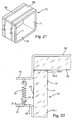
- ein aus einem U-förmigen Formteil und einem plattenförmigen Wandelement zusammengesetztes Ofenmuffelbauteil in perspektivischer Detailansicht,
- Fig. 22
- eine der
Fig. 21 entnommene Detailansicht, - Fig. 23
- abschnittsweise ein Umreifungselement in perspektivischer Darstellung und
- Fig. 24
- eine Detailansicht einer Ofenmuffel in Frontansicht.
- Die
Fig. 1 zeigt einen flächenförmigen rechteckigen Zuschnitt 10.1 aus Glas oder Glaskeramik, der von einem Glas/Glaskeramikband abgehängt ist. Auf der Oberseite des Zuschnitts 10.1 ist ein durchgehender Vorsprung 17 anprofiliert, der während des Walzens das Glasband aus der Schmelze ausgeformt ist. In derFig. 1 sind gestrichelte Biegelinien 18.1 angedeutet, die in Breitenrichtung des Zuschnitts 10.1 verlaufen. An diesen Biegelinien 18.1 wird der Zuschnitt 10.1 zu dem inFig. 2 gezeigten Formteil 10 umgeformt. Dabei werden zwei vertikale seitliche Wandelemente 11 U-förmig von einem horizontalen Wandelement 12 an den Biegelinien 18.1 unter Bildung gerundeter Biegekanten 18 abgebogen. Die Wandelemente 11 stehen zueinander parallel und senkrecht zum Wandelement 12. Denkbar ist auch, dass die Wandelemente 11 in einem Winkel größer als 90° zu dem Wandelement 12 V-förmig angestellt sind. - Wie die
Fig. 2 erkennen lässt, bildet der Vorsprung 17 im Bereich der Frontseite der Ofenmuffel eine Überlaufbarriere am Backofen (Wandelement 12), die ein Auslaufen von beispielsweise Fett verhindert. Die Innenflächen 13 der Wandelemente 11 und 12 gehen zugunsten einer guten Reinigbarkeit in den Kopplungsbereichen gerundet ineinander über. Die vorderseitigen und rückseitigen Kanten der Wandelemente 11 und 12 gehen bündig ineinander über, so dass sich ebene Dichtflächen 19.1 und 19.3 ergeben. Frontseitig kann daran eine Ofentür (nicht dargestellt) und rückseitig ein weiteres Wandelement (nicht dargestellt) abgedichtet angeschlagen werden. Die freien Enden der Wandelemente 11 bilden horizontale Dichtflächen 19.2. - In den
Fig. 2 und3 ist ein Zuschnitt 10.1 beziehungsweise ein Formteil 10 für eine Ofenmuffel beschrieben, die in ihrer Gestaltung dem Zuschnitt 10.1 und dem Formteil 10 gemäßFig. 1 und 2 entsprechen. Unterschiedlich ist lediglich die Ausbildung eines zweiten Vorsprunges 17. Dieser ist im rückseitigen Ofenmuffelbereich angeordnet. Zwischen den beiden bodenseitigen Vorsprüngen 17 und den jeweiligen Wandelementen 11 wird somit ein räumlich begrenzter Auffang gebildet. - In den
Fig. 5 und 6 sind Ausgestaltungen der Erfindung gezeigt, die derFig. 1 und 2 im Wesentlichen entsprechen. Wie dieFig. 5 erkennen lässt, ist in die Innenfläche 13 der die seitlichen Wandelemente 11 bildenden Zuschnittbereiche eine wellenförmige Profilierung eingetieft. Dabei sind schienenförmige Aufnahmen 15 abgebildet, die in Richtung der Ofenmuffeltiefe (entspricht Breite des Zuschnitts 10.1) verlaufen. Die Aufnahmen 15 sind dabei von den Vorsprüngen 16 der wellenförmigen Profilierungen begrenzt. Die Profilierung wird während des Walzens des Glasbandes aus der Schmelze ausgeprägt. Die Aufnahmen 15 der beiden Wandelemente 11 sind einander gegenüberliegend derart angeordnet, dass dort Backbleche oder Führungsschienen eingeschoben werden können. - Im Unterschied zu der Ausführung gem.
Fig. 5 und 6 kann die wellenförmige Profilierung sowohl in der Innen- als auch in der Außenfläche 13 und 14 der Wandelemente 11 vorgesehen sein, so dass sich insgesamt ein welliges Bild der seitlichen Muffelwandung (Wandelement 11) ergibt. Die Funktion der sich innenseitig ergebenden Aufnahmen 15 und Vorsprünge 16 entspricht der gemäßFig. 6 . Allerdings können die Vorsprünge 16 gemäßFig. 7 und 8 intensiver ausgeprägt werden. - In den
Fig. 9 bis 11 ist ein Formteil für eine Ofenmuffel gezeigt, bei der das bodenseitige Wandelement 12 zur Aufnahme von Überlauf eine Eintiefung 20 aufweist. Ausgehend von einer flachen Glaskeramik-Scheibe, wie inFig. 9 dargestellt, wird beim Umformprozess oder als nachgeschalteter separater Verformungsprozess eine Mulde im Bodenbereich abgesenkt. Diese muldenförmige Absenkung kann üblicherweise bei Wiedererwärmung allein durch die Schwerkraft der Glaskeramik-Scheibe erzeugt werden. - Die
Fig. 12 bis 14 zeigen ebenfalls die Ausbildung einer Bodenwanne zur Aufnahme von Überlaufvolumen. In diesem Fall ist die Bodenwanne allerdings durch eine Zwangsverformung des Vorläuferglases erzeugt worden, durch Pressen oder Vakuumsenken. Vorteil ist hier, dass größere und schärfer ausgeprägte Formen (Biegekanten 20.1 und 20.2) möglich sind, als bei der Herstellung wie inFig. 10 und 11 gezeigt. - In der
Fig. 15 ist ein Bauteil für eine Ofenmuffel dargestellt, das aus zwei U-förmigen Formteilen 10 zusammengesetzt ist, die bis auf den Vorsprung 17 entsprechendFig. 2 gefertigt und ausgestaltet sind. Die beiden Formteile 10 sind baugleich, weswegen nur ein Fertigungswerkzeug erforderlich ist. Die beiden Formteile 10 werden unter Zwischenlage eines Teflon- oder Graphit-Bandes als Dichtelement 19.4 im Bereich der Dichtflächen 19.2 gegeneinander gestellt. Damit ergibt sich ein umlaufender Rahmen, bei dem die seitlichen Wandelemente 11 der beiden Formteile 10 jeweils die Ofenmuffelseitenwände und die Wandelemente 12 jeweils die Ofenmuffeldeckenbeziehungsweise -bodenwand bilden. - Das rahmenartige Bauteil wird mit zwei Umreifungselementen 30, die als Spannbänder ausgebildet sind, in Form gehalten. Das Umreifungselement (30) ist als Metallband ausgeführt, das an seinen Bandenden mit nach außen gerichteten Abwinklungen 31 versehen ist. Aus den Abwinklungen 31 sind Laschen 31.1 freigestanzt und abgebogen. Die Laschen 31.1 weisen jeweils einen Durchbruch 31.2 auf. Die Umreifungselemente 30 werden vorder- bzw. rückseitig um den Rahmen geschlungen und die Bandenden aufeinander ausgerichtet. Zwischen dem Umreifungselement (30) und den Formteilen 10 kann ein Teflon- oder Graphitband als Kratzschutz eingelegt sein.
- Bei der Verbindung von Glaskeramik-Muffeln mit Metallteilen müssen grundsätzlich die unterschiedlichen Wärmeausdehnungen beider Materialien beachtet werden, da sich der Metallrahmen weitet oder aber wenn der Metallrahmen in der Backofenmuffel Innen eingreifen würde oder mit der Backofenmuffel fest verbunden wäre, würde die Glaskeramik-Muffel beim Aufheizen einreißen und zerbrechen. Aus diesem Grund sind die Bandenden des Umreifungselementes 30 mit einem Federelement 32 verbunden. Die Federenden sind in die Durchbrüche 31.2 der Abwinklungen 31 vorgespannt eingehangen. Damit wird dem unterschiedlichen Wärmeausdehnungsverhalten Rechnung getragen. Das Federelement 32 kann auch an anderer als der in
Fig. 16 gezeigten Stelle angeordnet sein. Denkbar ist es auch, dass die beiden Formteile 10 miteinander stoffschlüssig verbunden, beispielsweise verlötet oder verschweißt sind. - Die in den
Fig. 17 und 18 gezeigte Anordnung entspricht derFig. 14 und15 , wobei im Bereich der Stoßstellen der Formteile 10 Tragteile 40 in Form von Profilabschnitten eingesetzt sind. Die Tragteile 40 weisen eine Steg 40 auf, der im Bereich der Außenseite einen verdickten Ansatz 42 trägt. Innenseitig ist am Steg 40 ein Halteabschnitt 44 angeformt, der zwei Schenkel 45 trägt. Die Schenkel 45 sind zueinander parallel beabstandet. Von den Schenkelenden 45 gehen rechtwinklig Endabschnitte 46 ab, so dass sich eine hinterschnittene, in Tiefenrichtung verlaufende Aufnahme 43 ergibt. In dieser Aufnahme 43 können Befestigungsmittel (Gestelle, Backbleche, Laufrollen, Führungsschienen etc.) im Innenraum der Ofenmuffel gehalten und fixiert werden. Der Ansatz 42 und der Halteabschnitt 44 verhindern, dass das Tragteil 40 aus der Stoßstelle gezogen werden kann. Zwischen dem Steg 41 und den Dichtflächen 19.2 sind jeweils Dichtelemente 19.4 eingelegt. - Die Ausgestaltungsvariante nach
Fig. 19 und 20 unterscheidet sich von der nachFig. 17 und 18 dadurch, dass der Steg 41 des Tragteils 40 als Hohlprofil ausgebildet ist und Leuchtelemente 47 in Form einer Leuchtdioden-Kette zur Beleuchtung des Garraums aufnimmt. Denkbar ist selbstverständlich auch ein Tragteil 40, das keine Aufnahme 43 bildet und nur die Leuchtelemente 47 aufnimmt. - Ergänzend zu den in
Fig. 15 bis 20 gezeigten halbschaligen Formteilen 10 ist auch denkbar, die seitlichen Wandelemente 11 des U-Profils höher auszugestalten und als Muffeldeckel ein im Wesentlichen gerades Wandelement 50 in Form einer Glaskeramik-Scheibe aufzusetzen. Die Verbindung und Befestigung erfolgt analog den inFig. 15 bis 20 beschriebenen Möglichkeiten. - Zur Halterung der Backofenmuffel im gesamten Backherd wird vorgeschlagen, das Umreifungselement 30 mit ausgeprägter Lasche 33 zu versehen, wie in
Fig. 23 gezeigt. Die ausgeprägten Laschen 23 können über verbördeln, verschrauben, vernieten oder verschweißen mit einem Herdrahmen 60 flexibel verbunden werden. In dem Zwischenraum zwischen Herdrahmen und Backofenmuffel kann ein Dichtelement 34 in Form eines umlaufenden Gewebeschlauches eingeknipst werden. Dies ist eine bekannt Technik, wie sie heute bereits bei Pyrolysebacköfen Verwendung findet. Bei dieser Verbindungsart wird der unterschiedlichen Ausdehnung von Glaskeramik und Metall Rechnung getragen und es wird sichergestellt, dass durch thermische Ausdehnung kein Bruch der Backofenmuffel erzeugt wird. - Das Dichtelement 34 wird von einer Klammer 35 gehalten. Die Klammer 35 ist zwischen dem Umreifungselement 30 und dem Herdrahmen 60 angeordnet, wie dies
Fig. 24 veranschaulicht.
Claims (16)
- Ofenmuffel, insbesondere Backofenmuffel, mit mindestens zwei aneinander grenzenden Wandelementen (11, 12, 50), die einen insbesondere als Garraum dienenden Innenraum zumindest bereichsweise begrenzen,
wobei die Wandelemente (11, 12, 50) aus Glas oder Glaskeramik bestehen, wobei die benachbarten Wandelemente (11, 12, 50) zueinander im Winkel stehen,
wobei die Wandelemente (11, 12, 50) einstückig miteinander verbunden sind und ein Formteil (10) bilden,
wobei der Innenraum von wenigstens zwei Formteilen (10) oder von einem Formteil (10) und einem plattenartigen Wandelement (50) begrenzt ist,
dadurch gekennzeichnet,
dass im Bereich der Stoßstelle zweier aneinander gesetzter Formteile (10) oder im Bereich der Stoßstelle eines Formteils (10) mit einem plattenartigen Wandelement (50) ein Tragteil (40) gehalten ist. - Ofenmuffel nach Anspruch 1,
dadurch gekennzeichnet,
dass das Formteil (10) drei Wandelemente (11, 12) aufweist, und dass die Wandelemente (11, 12) derart angeordnet sind, dass das Formteil im Wesentlichen V- oder U-förmig ausgebildet ist. - Ofenmuffel nach Anspruch 2,
dadurch gekennzeichnet,
dass von dem als Boden- oder Deckwand ausgebildeten Wandelement (13) an gegenüberliegenden Wandelementen die beiden als Seitenwände ausgebildeten Wandelemente (11) abgebogen sind (Biegekante 18). - Ofenmuffel nach einem der Ansprüche 1 bis 3,
dadurch gekennzeichnet,
dass der Ofenmuffelvorder- und/oder -rückseite zugewandte Begrenzungsränder der gegeneinander abgebogenen Wandelemente (11, 12) zur Bildung einer ebenen Dichtfläche (19.1 und/oder 19.3) ineinander übergehen, und/oder
dass wenigstens eines der Wandelemente (11, 12) an seiner dem anderen, angeformten Wandelement (11, 12) abgewandten Seite eine ebene Dichtfläche (19.2) bildet. - Ofenmuffel nach einem der Ansprüche 1 bis 4,
dadurch gekennzeichnet,
dass wenigstens eines der Wandelemente (11, 12) wenigstens ein einstückig angeformtes Funktionselement, insbesonder einen Vorsprung (16, 17), eine Aufnahme (15) oder eine Eintiefung (20), aufweist, das in die dem Innenraum zugewandte Innenfläche (13) des Wandelements (11, 12) eingeformt ist oder in den Innenraum vorstehend von der Innenfläche (13) vorsteht. - Ofenmuffel nach Anspruch 5,
dadurch gekennzeichnet,
dass das Funktionselement ein Vorsprung (17) ist, der im Bereich der Vorder- und/oder Rückseite der Ofenmuffel an das den Ofenmuffelboden und/oder die Ofenmuffelseilenwände bildenden Wandelemente (11, 12) ein- oder angeformt ist. - Ofenmuffel nach Anspruch 5 oder 6,
dadurch gekennzeichnet,
dass die Funktionselemente in Form von Aufnahmen (15) in wenigstens eine der die Ofenmuffelseitenwände bildenden Wandelemente (11, 12) an- oder eingeformt sind. - Ofenmuffel nach Anspruch 7,
dadurch gekennzeichnet,
dass an den beiden, die Ofenmuffeiseitenwände bildenden Wandelementen (11) Aufnahmen (15) angeordnet sind, die in Richtung der Ofenmuffeltiefe verlaufende Führungen für Backbleche bilden. - Ofenmuffel nach einem der Ansprüche 5 bis 8,
dadurch gekennzeichnet,
dass das den Ofenmuffelboden bildende Wandelement (12) eine, in die Innenfläche (13) eingeformte Eintiefung (20) aufweist. - Ofenmuffel nach einem der Ansprüche 1 bis 9.
dadurch gekennzeichnet,
dass die Formteile (10) rahmenartig den Ofenmuffelboden, die beiden Ofenmuffelseitenwände und den Ofenmuffeldeckel bilden. - Ofenmuffel nach einem der Ansprüche 1 bis 9,
dadurch gekennzeichnet,
dass an dem Formteil (10) wenigstens ein plattenartiges Wandelement (50) gehalten ist, das den Innraum begrenzt. - Ofenmuffel nach Anspruch 11,
dadurch gekennzeichnet,
dass das Formteil (10) und das wenigstens eine plattenartige Wandelement (50) rahmenartig den Ofenmuffelboden, die beiden Ofenmuffelseitenwände und den Ofenmuffeldeckel bilden. - Ofenmuffel nach einem der Ansprüche 1 bis 12,
dadurch gekennzeichnet,
dass die Formteile oder das Formteil (10) und das plattenartige Wandelement (50) mittels Umreifungselementen (30) gegeneinander verspannt sind. - Ofenmuffel nach Anspruch 13,
dadurch gekennzeichnet,
dass das Umreifungselement (30) zumindest bereichsweise federelastisch ausgebildet ist oder ein Federelement (32) aufweist. - Ofenmuffel nach einem der Ansprüche 1 bis 14,
dadurch gekennzeichnet,
dass das Tragteil (40) dem Innenraum zugewandt wenigstens eine Befestigungsaufnahme (43) aufweist. - Ofenmuffel nach einem der vorhergehenden Ansprüche,
dadurch gekennzeichnet,
dass das Umreifungselement (30) Halteelemente (33) aufweist und/oder, dass das Tragteil wenigstens ein Leuchtelement (47) aufweist und/oder, dass das Umreifungselement (30) ein Dichtelement (34) trägt.
Applications Claiming Priority (1)
| Application Number | Priority Date | Filing Date | Title |
|---|---|---|---|
| DE200810025907 DE102008025907B4 (de) | 2008-05-29 | 2008-05-29 | Ofenmuffel |
Publications (3)
| Publication Number | Publication Date |
|---|---|
| EP2128529A2 EP2128529A2 (de) | 2009-12-02 |
| EP2128529A3 EP2128529A3 (de) | 2009-12-30 |
| EP2128529B1 true EP2128529B1 (de) | 2016-09-14 |
Family
ID=40887168
Family Applications (1)
| Application Number | Title | Priority Date | Filing Date |
|---|---|---|---|
| EP09005032.9A Not-in-force EP2128529B1 (de) | 2008-05-29 | 2009-04-04 | Ofenmuffel |
Country Status (5)
| Country | Link |
|---|---|
| US (1) | US8794226B2 (de) |
| EP (1) | EP2128529B1 (de) |
| JP (1) | JP5582724B2 (de) |
| CN (1) | CN101592347B (de) |
| DE (1) | DE102008025907B4 (de) |
Families Citing this family (9)
| Publication number | Priority date | Publication date | Assignee | Title |
|---|---|---|---|---|
| USD569491S1 (en) * | 2007-07-02 | 2008-05-20 | Saint-Gobain Ceramics & Plastics, Inc. | Interconnecting muffle |
| ITPD20070420A1 (it) * | 2007-12-20 | 2009-06-21 | Unox S R L | Struttura di forno a muffola, particolarmente per la cottura di prodotti alimentari |
| EP2615377B1 (de) * | 2012-01-13 | 2017-05-03 | Electrolux Home Products Corporation N.V. | Ofeninnenraum und Ofen |
| DE102013018465A1 (de) | 2013-11-05 | 2015-05-07 | Schott Ag | Körper aus einem sprödbrüchigen Material und einem metallischen Material sowie ein Verfahren zur Herstellung einer stoffschlüssigen Verbindung eines sprödbrüchigen Materials und eines metallischen Materials |
| USD900545S1 (en) * | 2017-07-24 | 2020-11-03 | Regale Microwave Ovens Ltd | Microwave oven cavity liner |
| USD901228S1 (en) | 2017-07-24 | 2020-11-10 | Regale Microwave Ovens Ltd | Microwave oven cavity liner |
| US12016105B2 (en) | 2019-11-25 | 2024-06-18 | Bsh Home Appliances Corporation | Home appliance cavity |
| DE102021100667A1 (de) * | 2021-01-14 | 2022-07-14 | Lothar Schmid | Vorrichtung zur Verbindung wenigstens zweier Wandelemente eines Heizofens, Verkleidung für einen Heizofen und Heizofen |
| US20250116409A1 (en) * | 2023-10-10 | 2025-04-10 | Whirlpool Corporation | Cooking appliance |
Family Cites Families (32)
| Publication number | Priority date | Publication date | Assignee | Title |
|---|---|---|---|---|
| US3143638A (en) * | 1962-09-27 | 1964-08-04 | Gen Electric | Convertible drawer oven |
| US3410987A (en) * | 1966-05-12 | 1968-11-12 | Gen Electric | Electric baking oven with a front heating element |
| US3452183A (en) * | 1967-04-12 | 1969-06-24 | Electro Therm | Composite oven liner and heating element structure for self-cleaning ovens |
| US4262183A (en) * | 1979-09-24 | 1981-04-14 | General Electric Company | Combination microwave/forced convection oven |
| DE3231462C1 (de) * | 1982-08-24 | 1984-05-24 | Bosch-Siemens Hausgeräte GmbH, 7000 Stuttgart | Thermisch belastetes Blechteil, insbesondere Ofenmuffel und Verfahren zu dessen Herstellung |
| DE3302794A1 (de) | 1983-01-28 | 1984-08-02 | Miele & Cie GmbH & Co, 4830 Gütersloh | Backmuffel fuer einen elektroherd |
| DE3527957C2 (de) | 1985-08-03 | 1996-06-20 | Aeg Hausgeraete Gmbh | Backofenmuffel aus Glas oder Glaskeramik |
| DE3527958C2 (de) | 1985-08-03 | 1994-01-20 | Licentia Gmbh | Back- und Bratrohr |
| DE3643371A1 (de) * | 1986-12-18 | 1988-06-23 | Bosch Siemens Hausgeraete | Beleuchtungseinrichtung fuer einen backofen |
| JPH0646097B2 (ja) * | 1987-01-30 | 1994-06-15 | 松下電器産業株式会社 | 加熱調理器 |
| DE3715711A1 (de) * | 1987-05-12 | 1988-11-24 | Ruhrkohle Ag | Keramikhohlstopfen fuer koksofentueren |
| US5036179A (en) | 1988-05-19 | 1991-07-30 | Quadlux, Inc. | Visible light and infra-red cooking apparatus |
| FR2732451B1 (fr) * | 1995-03-31 | 1997-06-27 | Cidelcem Ind | Dispositif de raccordement de deux segments successifs d'un four de tunnel de cuisson d'aliments |
| US5670181A (en) * | 1995-10-20 | 1997-09-23 | Stokes; Christine P. | Apparatus and method for slip casting for ceramic objects |
| CA2183498A1 (en) | 1995-11-13 | 1997-05-14 | Walton E. Sparks | Ceran smooth bottom range |
| DE19638663A1 (de) * | 1996-09-20 | 1998-03-26 | Bosch Siemens Hausgeraete | Backofenmodul mit integrierten Heizungen und evakuierter Ummantelung |
| US5918885A (en) * | 1997-03-11 | 1999-07-06 | Federal-Mogul Systems Protection Group, Inc. | Tubular articles with externally installed attachment clips |
| JP4371395B2 (ja) | 1999-01-08 | 2009-11-25 | カドラックス・インク | 走査型光波オーブン及びその操作方法 |
| DE10066132B3 (de) * | 2000-06-29 | 2004-02-05 | BSH Bosch und Siemens Hausgeräte GmbH | Backofen |
| JP2002130692A (ja) * | 2000-10-24 | 2002-05-09 | Toshiba Corp | 加熱調理器 |
| DE10104501B4 (de) * | 2001-01-31 | 2004-06-24 | BSH Bosch und Siemens Hausgeräte GmbH | Gargerät |
| DE10203607A1 (de) | 2002-01-30 | 2003-07-31 | Bsh Bosch Siemens Hausgeraete | Lichtwellenofen mit Kühlkanal |
| DE10203609A1 (de) | 2002-01-30 | 2003-07-31 | Bsh Bosch Siemens Hausgeraete | Lichtwellenofen mit schwenkbarem Lampenreflektor |
| DE10203610A1 (de) | 2002-01-30 | 2003-07-31 | Bsh Bosch Siemens Hausgeraete | Lichtwellenofen mit Strahlungslampen unterschiedlicher Farbtemperatur |
| US6589049B1 (en) * | 2002-05-03 | 2003-07-08 | Igs, Inc. | Rotary kiln seal |
| MXPA05001304A (es) * | 2002-08-06 | 2005-10-06 | Cavity Prot Systems Ltd | Revestimiento de horno. |
| DE102004003408A1 (de) * | 2004-01-23 | 2005-08-18 | Electrolux Schwanden Ag | Ofenmuffel für einen Garofen mit Mikrowellenbetrieb |
| ITPD20040270A1 (it) * | 2004-11-03 | 2005-02-03 | Unox Spa | Struttura perfezionata di muffola |
| CN1895058A (zh) * | 2005-07-15 | 2007-01-17 | 乐金电子(天津)电器有限公司 | 电烤箱烤箱部构造 |
| JP2007315697A (ja) * | 2006-05-26 | 2007-12-06 | Toshiba Corp | 加熱調理器 |
| ITPD20060400A1 (it) * | 2006-10-31 | 2008-05-01 | Unox Spa | "struttura di muffola" |
| FR2911385A1 (fr) * | 2007-01-12 | 2008-07-18 | P H T Premium Heating Technolo | Moufle de cuisson en verre pour enceinte de cuisson et enceinte equipee d'un tel moufle. |
-
2008
- 2008-05-29 DE DE200810025907 patent/DE102008025907B4/de not_active Expired - Fee Related
-
2009
- 2009-04-04 EP EP09005032.9A patent/EP2128529B1/de not_active Not-in-force
- 2009-05-22 JP JP2009123787A patent/JP5582724B2/ja not_active Expired - Fee Related
- 2009-05-27 CN CN200910142019.9A patent/CN101592347B/zh not_active Expired - Fee Related
- 2009-05-29 US US12/455,305 patent/US8794226B2/en not_active Expired - Fee Related
Non-Patent Citations (1)
| Title |
|---|
| None * |
Also Published As
| Publication number | Publication date |
|---|---|
| DE102008025907B4 (de) | 2015-04-30 |
| DE102008025907A1 (de) | 2009-12-03 |
| EP2128529A2 (de) | 2009-12-02 |
| JP2009287916A (ja) | 2009-12-10 |
| EP2128529A3 (de) | 2009-12-30 |
| US8794226B2 (en) | 2014-08-05 |
| CN101592347B (zh) | 2013-07-10 |
| US20090301460A1 (en) | 2009-12-10 |
| JP5582724B2 (ja) | 2014-09-03 |
| CN101592347A (zh) | 2009-12-02 |
Similar Documents
| Publication | Publication Date | Title |
|---|---|---|
| DE102008025907B4 (de) | Ofenmuffel | |
| DE19703301C2 (de) | Gaskochgerät | |
| DE102016224755A1 (de) | Haushaltsgargerät | |
| DE102009028808A1 (de) | Innenrahmen für Dunstabzugshaube und Dunstabzugshaube | |
| DE102021212761A1 (de) | Garraumeinsatz mit spezifischem Grundaufbau, sowie Gargerät | |
| EP1867927A2 (de) | Tür eines Garofens, insbesondere eines Haushaltsgarofens, sowie Verfahren zur Herstellung | |
| EP4185814B1 (de) | Tür und haushaltsgargerät | |
| DE102010003700A1 (de) | Topfträger und Gaskochstelle | |
| EP1340021A1 (de) | Backofen | |
| DE102005036815B4 (de) | Backofen | |
| EP1178264B1 (de) | Tür für ein Haushaltsgerät, inbesondere einen Haushaltsgarofen | |
| DE19801081C2 (de) | Wärmegerät, ausgebildet als Etagenheizung und/oder Durchlauferhitzer | |
| DE3128944C2 (de) | Auflagerost für einen Herd mit Back- und Bratraum | |
| DE10314214B4 (de) | Ofentür zum Verschließen einer Ofenmuffel eines Backofens | |
| DE3602398C2 (de) | ||
| AT403404B (de) | Ofen, insbesondere kaminofen | |
| EP2520866B1 (de) | Backofen | |
| WO2007088090A2 (de) | Gargerät, insbesondere hocheinbau-gargerät, und verfahren zu dessen herstellung | |
| DE19947153A1 (de) | Einschubvorrichtung für Gargutträger im Garraum von Garöfen | |
| DE10207280A1 (de) | Topfträger für Gasmulden | |
| DE29701494U1 (de) | Gaskochgerät | |
| DE9390017U1 (de) | Heizeinrichtung mit einem aus Blechelementen zusammengesetzten Ofenkörper | |
| DE102008064301A1 (de) | Ofenmuffel | |
| DE102007004625A1 (de) | Gargerät, insbesondere Hocheinbau-Gargerät, und Verfahren zu dessen Herstellung | |
| DE102008040844A1 (de) | Dunstabzugsvorrichtung sowie Verfahren zur Herstellung einer solchen Dunstabzugsvorrichtung |
Legal Events
| Date | Code | Title | Description |
|---|---|---|---|
| PUAI | Public reference made under article 153(3) epc to a published international application that has entered the european phase |
Free format text: ORIGINAL CODE: 0009012 |
|
| PUAL | Search report despatched |
Free format text: ORIGINAL CODE: 0009013 |
|
| AK | Designated contracting states |
Kind code of ref document: A2 Designated state(s): AT BE BG CH CY CZ DE DK EE ES FI FR GB GR HR HU IE IS IT LI LT LU LV MC MK MT NL NO PL PT RO SE SI SK TR |
|
| AK | Designated contracting states |
Kind code of ref document: A3 Designated state(s): AT BE BG CH CY CZ DE DK EE ES FI FR GB GR HR HU IE IS IT LI LT LU LV MC MK MT NL NO PL PT RO SE SI SK TR |
|
| 17P | Request for examination filed |
Effective date: 20100630 |
|
| 17Q | First examination report despatched |
Effective date: 20150914 |
|
| GRAP | Despatch of communication of intention to grant a patent |
Free format text: ORIGINAL CODE: EPIDOSNIGR1 |
|
| INTG | Intention to grant announced |
Effective date: 20160630 |
|
| GRAS | Grant fee paid |
Free format text: ORIGINAL CODE: EPIDOSNIGR3 |
|
| GRAA | (expected) grant |
Free format text: ORIGINAL CODE: 0009210 |
|
| AK | Designated contracting states |
Kind code of ref document: B1 Designated state(s): AT BE BG CH CY CZ DE DK EE ES FI FR GB GR HR HU IE IS IT LI LT LU LV MC MK MT NL NO PL PT RO SE SI SK TR |
|
| REG | Reference to a national code |
Ref country code: GB Ref legal event code: FG4D Free format text: NOT ENGLISH |
|
| REG | Reference to a national code |
Ref country code: CH Ref legal event code: EP |
|
| REG | Reference to a national code |
Ref country code: IE Ref legal event code: FG4D Free format text: LANGUAGE OF EP DOCUMENT: GERMAN |
|
| REG | Reference to a national code |
Ref country code: AT Ref legal event code: REF Ref document number: 829436 Country of ref document: AT Kind code of ref document: T Effective date: 20161015 |
|
| REG | Reference to a national code |
Ref country code: DE Ref legal event code: R096 Ref document number: 502009013082 Country of ref document: DE |
|
| REG | Reference to a national code |
Ref country code: LT Ref legal event code: MG4D |
|
| REG | Reference to a national code |
Ref country code: NL Ref legal event code: MP Effective date: 20160914 |
|
| PG25 | Lapsed in a contracting state [announced via postgrant information from national office to epo] |
Ref country code: HR Free format text: LAPSE BECAUSE OF FAILURE TO SUBMIT A TRANSLATION OF THE DESCRIPTION OR TO PAY THE FEE WITHIN THE PRESCRIBED TIME-LIMIT Effective date: 20160914 Ref country code: LT Free format text: LAPSE BECAUSE OF FAILURE TO SUBMIT A TRANSLATION OF THE DESCRIPTION OR TO PAY THE FEE WITHIN THE PRESCRIBED TIME-LIMIT Effective date: 20160914 Ref country code: NO Free format text: LAPSE BECAUSE OF FAILURE TO SUBMIT A TRANSLATION OF THE DESCRIPTION OR TO PAY THE FEE WITHIN THE PRESCRIBED TIME-LIMIT Effective date: 20161214 Ref country code: FI Free format text: LAPSE BECAUSE OF FAILURE TO SUBMIT A TRANSLATION OF THE DESCRIPTION OR TO PAY THE FEE WITHIN THE PRESCRIBED TIME-LIMIT Effective date: 20160914 |
|
| PG25 | Lapsed in a contracting state [announced via postgrant information from national office to epo] |
Ref country code: SE Free format text: LAPSE BECAUSE OF FAILURE TO SUBMIT A TRANSLATION OF THE DESCRIPTION OR TO PAY THE FEE WITHIN THE PRESCRIBED TIME-LIMIT Effective date: 20160914 Ref country code: ES Free format text: LAPSE BECAUSE OF FAILURE TO SUBMIT A TRANSLATION OF THE DESCRIPTION OR TO PAY THE FEE WITHIN THE PRESCRIBED TIME-LIMIT Effective date: 20160914 Ref country code: LV Free format text: LAPSE BECAUSE OF FAILURE TO SUBMIT A TRANSLATION OF THE DESCRIPTION OR TO PAY THE FEE WITHIN THE PRESCRIBED TIME-LIMIT Effective date: 20160914 Ref country code: GR Free format text: LAPSE BECAUSE OF FAILURE TO SUBMIT A TRANSLATION OF THE DESCRIPTION OR TO PAY THE FEE WITHIN THE PRESCRIBED TIME-LIMIT Effective date: 20161215 Ref country code: NL Free format text: LAPSE BECAUSE OF FAILURE TO SUBMIT A TRANSLATION OF THE DESCRIPTION OR TO PAY THE FEE WITHIN THE PRESCRIBED TIME-LIMIT Effective date: 20160914 |
|
| REG | Reference to a national code |
Ref country code: FR Ref legal event code: PLFP Year of fee payment: 9 |
|
| PG25 | Lapsed in a contracting state [announced via postgrant information from national office to epo] |
Ref country code: EE Free format text: LAPSE BECAUSE OF FAILURE TO SUBMIT A TRANSLATION OF THE DESCRIPTION OR TO PAY THE FEE WITHIN THE PRESCRIBED TIME-LIMIT Effective date: 20160914 Ref country code: RO Free format text: LAPSE BECAUSE OF FAILURE TO SUBMIT A TRANSLATION OF THE DESCRIPTION OR TO PAY THE FEE WITHIN THE PRESCRIBED TIME-LIMIT Effective date: 20160914 |
|
| PG25 | Lapsed in a contracting state [announced via postgrant information from national office to epo] |
Ref country code: CZ Free format text: LAPSE BECAUSE OF FAILURE TO SUBMIT A TRANSLATION OF THE DESCRIPTION OR TO PAY THE FEE WITHIN THE PRESCRIBED TIME-LIMIT Effective date: 20160914 Ref country code: PL Free format text: LAPSE BECAUSE OF FAILURE TO SUBMIT A TRANSLATION OF THE DESCRIPTION OR TO PAY THE FEE WITHIN THE PRESCRIBED TIME-LIMIT Effective date: 20160914 Ref country code: SK Free format text: LAPSE BECAUSE OF FAILURE TO SUBMIT A TRANSLATION OF THE DESCRIPTION OR TO PAY THE FEE WITHIN THE PRESCRIBED TIME-LIMIT Effective date: 20160914 Ref country code: PT Free format text: LAPSE BECAUSE OF FAILURE TO SUBMIT A TRANSLATION OF THE DESCRIPTION OR TO PAY THE FEE WITHIN THE PRESCRIBED TIME-LIMIT Effective date: 20170116 Ref country code: IS Free format text: LAPSE BECAUSE OF FAILURE TO SUBMIT A TRANSLATION OF THE DESCRIPTION OR TO PAY THE FEE WITHIN THE PRESCRIBED TIME-LIMIT Effective date: 20170114 Ref country code: BG Free format text: LAPSE BECAUSE OF FAILURE TO SUBMIT A TRANSLATION OF THE DESCRIPTION OR TO PAY THE FEE WITHIN THE PRESCRIBED TIME-LIMIT Effective date: 20161214 |
|
| REG | Reference to a national code |
Ref country code: DE Ref legal event code: R097 Ref document number: 502009013082 Country of ref document: DE |
|
| PG25 | Lapsed in a contracting state [announced via postgrant information from national office to epo] |
Ref country code: IT Free format text: LAPSE BECAUSE OF FAILURE TO SUBMIT A TRANSLATION OF THE DESCRIPTION OR TO PAY THE FEE WITHIN THE PRESCRIBED TIME-LIMIT Effective date: 20160914 |
|
| PLBE | No opposition filed within time limit |
Free format text: ORIGINAL CODE: 0009261 |
|
| STAA | Information on the status of an ep patent application or granted ep patent |
Free format text: STATUS: NO OPPOSITION FILED WITHIN TIME LIMIT |
|
| PG25 | Lapsed in a contracting state [announced via postgrant information from national office to epo] |
Ref country code: DK Free format text: LAPSE BECAUSE OF FAILURE TO SUBMIT A TRANSLATION OF THE DESCRIPTION OR TO PAY THE FEE WITHIN THE PRESCRIBED TIME-LIMIT Effective date: 20160914 |
|
| PGFP | Annual fee paid to national office [announced via postgrant information from national office to epo] |
Ref country code: FR Payment date: 20170419 Year of fee payment: 9 |
|
| 26N | No opposition filed |
Effective date: 20170615 |
|
| PG25 | Lapsed in a contracting state [announced via postgrant information from national office to epo] |
Ref country code: SI Free format text: LAPSE BECAUSE OF FAILURE TO SUBMIT A TRANSLATION OF THE DESCRIPTION OR TO PAY THE FEE WITHIN THE PRESCRIBED TIME-LIMIT Effective date: 20160914 |
|
| REG | Reference to a national code |
Ref country code: CH Ref legal event code: PL |
|
| GBPC | Gb: european patent ceased through non-payment of renewal fee |
Effective date: 20170404 |
|
| REG | Reference to a national code |
Ref country code: IE Ref legal event code: MM4A |
|
| PG25 | Lapsed in a contracting state [announced via postgrant information from national office to epo] |
Ref country code: MC Free format text: LAPSE BECAUSE OF FAILURE TO SUBMIT A TRANSLATION OF THE DESCRIPTION OR TO PAY THE FEE WITHIN THE PRESCRIBED TIME-LIMIT Effective date: 20160914 |
|
| PG25 | Lapsed in a contracting state [announced via postgrant information from national office to epo] |
Ref country code: CH Free format text: LAPSE BECAUSE OF NON-PAYMENT OF DUE FEES Effective date: 20170430 Ref country code: LI Free format text: LAPSE BECAUSE OF NON-PAYMENT OF DUE FEES Effective date: 20170430 Ref country code: LU Free format text: LAPSE BECAUSE OF NON-PAYMENT OF DUE FEES Effective date: 20170404 Ref country code: GB Free format text: LAPSE BECAUSE OF NON-PAYMENT OF DUE FEES Effective date: 20170404 |
|
| REG | Reference to a national code |
Ref country code: BE Ref legal event code: MM Effective date: 20170430 |
|
| PG25 | Lapsed in a contracting state [announced via postgrant information from national office to epo] |
Ref country code: IE Free format text: LAPSE BECAUSE OF NON-PAYMENT OF DUE FEES Effective date: 20170404 |
|
| PG25 | Lapsed in a contracting state [announced via postgrant information from national office to epo] |
Ref country code: BE Free format text: LAPSE BECAUSE OF NON-PAYMENT OF DUE FEES Effective date: 20170430 |
|
| REG | Reference to a national code |
Ref country code: AT Ref legal event code: MM01 Ref document number: 829436 Country of ref document: AT Kind code of ref document: T Effective date: 20170404 |
|
| PG25 | Lapsed in a contracting state [announced via postgrant information from national office to epo] |
Ref country code: AT Free format text: LAPSE BECAUSE OF NON-PAYMENT OF DUE FEES Effective date: 20170404 |
|
| PG25 | Lapsed in a contracting state [announced via postgrant information from national office to epo] |
Ref country code: MT Free format text: LAPSE BECAUSE OF FAILURE TO SUBMIT A TRANSLATION OF THE DESCRIPTION OR TO PAY THE FEE WITHIN THE PRESCRIBED TIME-LIMIT Effective date: 20160914 |
|
| PG25 | Lapsed in a contracting state [announced via postgrant information from national office to epo] |
Ref country code: FR Free format text: LAPSE BECAUSE OF NON-PAYMENT OF DUE FEES Effective date: 20180430 |
|
| PG25 | Lapsed in a contracting state [announced via postgrant information from national office to epo] |
Ref country code: HU Free format text: LAPSE BECAUSE OF FAILURE TO SUBMIT A TRANSLATION OF THE DESCRIPTION OR TO PAY THE FEE WITHIN THE PRESCRIBED TIME-LIMIT; INVALID AB INITIO Effective date: 20090404 |
|
| PG25 | Lapsed in a contracting state [announced via postgrant information from national office to epo] |
Ref country code: CY Free format text: LAPSE BECAUSE OF NON-PAYMENT OF DUE FEES Effective date: 20160914 |
|
| PG25 | Lapsed in a contracting state [announced via postgrant information from national office to epo] |
Ref country code: MK Free format text: LAPSE BECAUSE OF FAILURE TO SUBMIT A TRANSLATION OF THE DESCRIPTION OR TO PAY THE FEE WITHIN THE PRESCRIBED TIME-LIMIT Effective date: 20160914 |
|
| PG25 | Lapsed in a contracting state [announced via postgrant information from national office to epo] |
Ref country code: TR Free format text: LAPSE BECAUSE OF FAILURE TO SUBMIT A TRANSLATION OF THE DESCRIPTION OR TO PAY THE FEE WITHIN THE PRESCRIBED TIME-LIMIT Effective date: 20160914 |
|
| PGFP | Annual fee paid to national office [announced via postgrant information from national office to epo] |
Ref country code: DE Payment date: 20200420 Year of fee payment: 12 |
|
| REG | Reference to a national code |
Ref country code: DE Ref legal event code: R119 Ref document number: 502009013082 Country of ref document: DE |
|
| PG25 | Lapsed in a contracting state [announced via postgrant information from national office to epo] |
Ref country code: DE Free format text: LAPSE BECAUSE OF NON-PAYMENT OF DUE FEES Effective date: 20211103 |