EP2125255B1 - Führungsvorrichtung für die einbaustücke von arbeitswalzen - Google Patents
Führungsvorrichtung für die einbaustücke von arbeitswalzen Download PDFInfo
- Publication number
- EP2125255B1 EP2125255B1 EP07856037A EP07856037A EP2125255B1 EP 2125255 B1 EP2125255 B1 EP 2125255B1 EP 07856037 A EP07856037 A EP 07856037A EP 07856037 A EP07856037 A EP 07856037A EP 2125255 B1 EP2125255 B1 EP 2125255B1
- Authority
- EP
- European Patent Office
- Prior art keywords
- guide
- guides
- bending block
- guide device
- bending
- Prior art date
- Legal status (The legal status is an assumption and is not a legal conclusion. Google has not performed a legal analysis and makes no representation as to the accuracy of the status listed.)
- Active
Links
Images


Classifications
-
- B—PERFORMING OPERATIONS; TRANSPORTING
- B21—MECHANICAL METAL-WORKING WITHOUT ESSENTIALLY REMOVING MATERIAL; PUNCHING METAL
- B21B—ROLLING OF METAL
- B21B31/00—Rolling stand structures; Mounting, adjusting, or interchanging rolls, roll mountings, or stand frames
- B21B31/02—Rolling stand frames or housings; Roll mountings ; Roll chocks
-
- B—PERFORMING OPERATIONS; TRANSPORTING
- B21—MECHANICAL METAL-WORKING WITHOUT ESSENTIALLY REMOVING MATERIAL; PUNCHING METAL
- B21B—ROLLING OF METAL
- B21B29/00—Counter-pressure devices acting on rolls to inhibit deflection of same under load, e.g. backing rolls ; Roll bending devices, e.g. hydraulic actuators acting on roll shaft ends
Definitions
- the invention relates to a guide device for the chocks of work rolls of a rolling mill with fixed to the inner sides of the windows of the rolling mill or horizontally arranged guides, wherein the upper and the lower bending block each page are each associated with two mutually parallel guides.
- Examples of such guiding devices are in DE 39 06 618 C2 or the EP 768 125 B1 disclosed.
- each bending block In the DE 39 06 618 C2 holding pieces are provided, each holding two pairs of guides, which are guided on these guides the bending blocks for the upper and lower chock.
- bushes or similar elements are provided, which are provided at the respective ends of the bending blocks.
- each bending block on a guide bore which is also provided with a provokeslement.
- the invention has for its object to simplify the guide for the bending blocks and in particular to avoid or substantially reduce the friction occurring in the known systems.
- a guide device for the chocks of work rolls of a rolling stand with fixed to the inner sides of the window of the rolling stand or horizontally movable guides, wherein the upper and the lower bending block each side are associated with two mutually parallel guides, which thereby is characterized in that each bending block is associated with one of the guides, while it has a recess encompassing this for the parallel guide, wherein the upper Bending block is guided on one of the parallel guides and the lower bending block on the other guide.
- each bending block has only one tube, which receives two slide bushings, so that this guide performs the actual leadership task.
- a recess is then provided in this bending block.
- associated other bending block serves this guide, for which a recess is provided in the aforementioned bending block, as the actual guide, while there is provided for the other guide a recess.
- Bushings can be provided as plain bearings in the bending block.
- anti-rotation sliding plates are provided on the front of the back bracket.
- the guides can be designed as circular guides.
- the guides are fastened by means of a holder in turn on the rolling stand.
- the guide device can be provided with a horizontal displacement system.
- the bending system consists of 4 units 1 each with 2 bending blocks 2,3 or 4,5 and a holder 20.
- two bending cylinders 12 which engage with their rod end 13 at the upper bending block, are seated in the lower bending block.
- a version with a cylinder is also possible.
- the rear bracket 20 also serves as a vertical stop for the cylinder movements.
- the work roll chocks were designed in their contour so that the line of action of the bending cylinder is as close to the center of the bearing. This results in a different contour from the previously used design, but the advantages of fast roll change are retained.
- the bending system can be used in conventional design, as well as in connection with means for horizontal displacement (HS) of the work rolls. In both cases, the system can be combined with axial displacement devices (CVC, EDC, or similar).
- FIG. 3 is the holder 20 for the guide rods, in this case 6 and 7, shown enlarged.
- FIG. 4 Yet another embodiment of the horizontal displacement of the example of the guide rods 6 and 7. This takes place here via wedge surfaces 14 and 15 and a displacement drive 16th
Landscapes
- Engineering & Computer Science (AREA)
- Mechanical Engineering (AREA)
- Bending Of Plates, Rods, And Pipes (AREA)
- Metal Rolling (AREA)
- Actuator (AREA)
- Presses And Accessory Devices Thereof (AREA)
- Bearings For Parts Moving Linearly (AREA)
Description
- Die Erfindung betrifft eine Führungsvorrichtung für die Einbaustücke von Arbeitswalzen eines Walzgerüstes mit an den Innenseiten der Fenster des Walzgerüstes fest oder horizontal beweglich angeordneten Führungen, wobei dem oberen und dem unteren Biegeblock jeder Seite jeweils zwei parallel zueinander angeordnete Führungen zugeordnet sind.
- Beispiele für derartige Führungsvorrichtungen sind in der
DE 39 06 618 C2 oder derEP 768 125 B1 - Bei der
DE 39 06 618 C2 sind Haltestücke vorgesehen, die jeweils zwei Paar von Führungen halten, wobei auf diesen Führungen die Biegeblöcke für das obere bzw. das untere Einbaustück geführt sind. Für die Führung sind Führungsrohre,-buchsen oder vergleichbare Elemente vorgesehen, die an den jeweiligen Enden der Biegeblöcke vorgesehen sind. Zur Verdrehsicherung weist jeder Biegeblock eine Führungsbohrung auf, die ebenfalls mit einem Führungslement versehen ist. - Bei der aus der
EP 768 125 B1 - Der Erfindung liegt die Aufgabe zugrunde, die Führung für die Biegeblöcke zu vereinfachen und insbesondere die bei den bekannten Systemen auftretende Reibung zu vermeiden bzw. wesentlich zu verringern.
- Gelöst wird diese Aufgabe erfindungsgemäß mit einer Führungsvorrichtung für die Einbaustücke von Arbeitswalzen eines Walzgerüstes mit an den Innenseiten der Fenster des Walzgerüstes fest oder horizontal beweglich angeordneten Führungen, wobei dem oberen und dem unteren Biegeblock jeder Seite jeweils zwei parallel zueinander angeordnete Führungen zugeordnet sind, die dadurch gekennzeichnet ist, dass jedem Biegeblock eine der Führungen zugeordnet ist, während es für die parallel verlaufende Führung eine diese umgreifende Ausnehmung aufweist, wobei der obere Biegeblock auf der einen der parallelen Führungen geführt ist und der untere Biegeblock auf der anderen Führung.
- Hierbei handelt es sich um ein System, das wie das bisher bekannte System der Walzenbiegung mit Biegeblöcken (Führungsstücken) arbeitet. Grundsätzlich anders ist die Art und Weise in der die Biegeblöcke geführt werden. Dies dient dazu die Reibung im System signifikant zu verringern.
- Bei der erfindungsgemäßen Lösung sind ebenfalls zwei Führungen je Führungsvorrichtung vorgesehen, aber jeder Biegeblock weist nur ein Rohr auf, das zwei Gleitbuchsen aufnimmt, so dass diese Führung die eigentliche Führungsaufgabe wahrnimmt. Für die zweite Führung ist in diesem Biegeblock dann eine Ausnehmung vorgesehen. Beim zugeordneten anderen Biegeblock dient dann diese Führung, für die im vorher genannten Biegeblock eine Ausnehmung vorgesehen ist, als eigentliche Führung, während für die andere Führung dort eine Ausnehmung vorgesehen ist. Somit kommt für die Führung eines Biegeblockes jeweils nur eine Führung der Führungsvorrichtung zum Einsatz.
- Im Biegeblock können Buchsen als Gleitlager vorgesehen sein.
- Als Verdrehsicherung sind an der Vorderseite der rückseitigen Halterung Gleitplatten vorgesehen.
- Die Führungen können als Rundführungen ausgebildet sein.
- Vorzugsweise sind die Führungen mittels einer Halterung ihrerseits am Walzgerüst befestigt.
- Schließlich kann die Führungsvorrichtung mit einem Horizontalverschiebesystem versehen sein.
- Die erfindungsgemäße Lösung soll nachfolgend mit Bezug auf die Zeichnungen erläutert werden.
- Dabei zeigt:
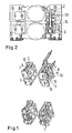
- Fig. 1
- eine perspektivische Darstellung der vier Biegeblöcke,
- Fig. 2
- eine Seitenansicht, teilweise geschnitten,
- Fig. 3
- die Halterung der Führungsstangen im Detail und
- Fig. 4
- ein Ausführungsbeispiel für die Horizontalverschiebung.
- Bei der Darstellung der erfindungsgemäßen Lösung wurden zur Vereinfachung nur die Teile dargestellt, auf die es für das Verständnis ankommt.
- Das Biegesystem besteht aus 4 Einheiten 1 mit je 2 Biegeblöcken 2,3 bzw. 4,5 und einer Halterung 20.
- Pro Halterung gibt es 2 Führungsstangen 6 und 7 bzw. 8 und 9, welche beispielsweise am Walzenständer befestigt ist. Auf jeder Führungstange 6 bzw. 7 ist jeweils ein Biegeblock geführt, und zwar der obere Biegeblock 2 der einen Seite auf der Führung 7, der untere Biegeblock 3 dieser Seite auf der Führung 6 und entsprechend auf der anderen Seite, der obere Biegeblock 4 auf der Führung 8 und der untere Biegeblock 5 auf der Führung 9. Bezogen auf den einen Biegeblock 2 ist dann für die andere Führung 6 eine Ausnehmung 10 vorgesehen. Der untere Biegeblock 3 dieser Seite umgreift dann die Führung 7 mit einer entsprechenden Ausnehmung teilweise.
Entsprechendes gilt für die Biegeblöcke der andere Seite. - Eine weitere Besonderheit im Gegensatz zu früheren Ausführungen ist hier die Länge der Führung.
Im Biegeblock sitzen Buchsen als Gleitlager, an der Halterung 20 sind Gleitleisten 11 als Verdrehsicherung vorgesehen. - Im unteren Biegeblock sitzen bei dem dargestellten Ausführungsbeispiel 2 Biegezylinder 12, die mit ihrem Stangenkopf 13 am oberen Biegeblock angreifen. Eine Ausführung mit einem Zylinder ist ebenfalls möglich. Die rückseitige Halterung 20 dient auch als vertikaler Anschlag für die Zylinderbewegungen.
- Die Arbeitswalzeneinbaustücke wurden in ihrer Kontur so gestaltet das die Wirkungslinie der Biegezylinder möglichst nahe der Lagermitte liegt. Daraus ergibt sich eine vom bisher verwendeten Design abweichende Kontur, jedoch bleiben die Vorteile des schnellen Walzenwechsels erhalten.
- Das Biegesystem ist einsetzbar in konventioneller Bauart, wie auch in Verbindung mit Einrichtungen zur horizontalen Verschiebung (HS) der Arbeitswalzen. In beiden Fällen ist das System kombinierbar mit Axialverschiebeeinrichtungen (CVC,EDC,o.ä.).
- In der
Figur 3 ist die Halterung 20 für die Führungsstangen, in diesem Fall 6 und 7, vergrößert dargestellt. - Schließlich zeigt die
Figur 4 noch ein Ausführungsbeispiel für die Horizontalverschiebung am Beispiel der Führungsstangen 6 und 7. Diese erfolgt hier über Keilflächen 14 und 15 und einen Verschiebeantrieb 16.
Claims (6)
- Führungsvorrichtung für die Einbaustücke von Arbeitswalzen eines Walzgerüstes mit an den Innenseiten der Fenster des Walzgerüstes fest oder horizontal beweglich angeordneten Führungen (6,7,8,9), wobei dem oberen und dem unteren Biegeblock (2,3;4,5) jeder Seite jeweils zwei parallel zueinander angeordnete Führungen (6,7;8,9) zugeordnet sind,
dadurch gekennzeichnet,
dass jedem Biegeblock (2-5) eine der Führungen (6-9) zugeordnet ist, während er für die parallel verlaufende Führung eine diese umgreifende Ausnehmung (10) aufweist, wobei der obere Biegeblock (2;4) auf der einen der parallelen Führungen (7;8) geführt ist und der untere Biegeblock (3;5) auf der anderen Führung (6;9). - Führungsvorrichtung nach Anspruch 1,
dadurch gekennzeichnet,
dass im Biegeblock Buchsen als Gleitlager vorgesehen sind. - Führungsvorrichtung nach einem der vorstehenden Ansprüche,
dadurch gekennzeichnet,
dass an der Vorderseite der rückseitigen Halterung (20) Gleitplatten (11) als Verdrehsicherung vorgesehen sind: - Führungsvorrichtung nach einem der vorstehenden Ansprüche,
dadurch gekennzeichnet,
dass die Führungen als Rundführungen ausgebildet sind. - Führungsvorrichtung nach einem der vorstehenden Ansprüche,
dadurch gekennzeichnet,
dass die Führungen mittels einer Halterung (20) ihrerseits am Walzgerüst befestigt sind. - Führungsvorrichtung nach einem der vorstehenden Ansprüche,
dadurch gekennzeichnet,
dass sie mit einem Horizontalverschiebesystem versehen ist.
Applications Claiming Priority (2)
| Application Number | Priority Date | Filing Date | Title |
|---|---|---|---|
| DE102007001322A DE102007001322A1 (de) | 2007-01-03 | 2007-01-03 | Führungsvorrichtung für die Einbaustücke von Arbeitswalzen |
| PCT/DE2007/002144 WO2008080376A1 (de) | 2007-01-03 | 2007-11-27 | Führungsvorrichtung für die einbaustücke von arbeitswalzen |
Publications (2)
| Publication Number | Publication Date |
|---|---|
| EP2125255A1 EP2125255A1 (de) | 2009-12-02 |
| EP2125255B1 true EP2125255B1 (de) | 2011-10-19 |
Family
ID=39149344
Family Applications (1)
| Application Number | Title | Priority Date | Filing Date |
|---|---|---|---|
| EP07856037A Active EP2125255B1 (de) | 2007-01-03 | 2007-11-27 | Führungsvorrichtung für die einbaustücke von arbeitswalzen |
Country Status (12)
| Country | Link |
|---|---|
| US (1) | US8225637B2 (de) |
| EP (1) | EP2125255B1 (de) |
| JP (1) | JP5386368B2 (de) |
| KR (1) | KR101127408B1 (de) |
| CN (1) | CN101563173B (de) |
| AT (1) | ATE529200T1 (de) |
| BR (1) | BRPI0720753B1 (de) |
| CA (1) | CA2674126C (de) |
| DE (1) | DE102007001322A1 (de) |
| ES (1) | ES2373127T3 (de) |
| RU (1) | RU2429924C2 (de) |
| WO (1) | WO2008080376A1 (de) |
Families Citing this family (4)
| Publication number | Priority date | Publication date | Assignee | Title |
|---|---|---|---|---|
| DE10243677A1 (de) * | 2002-09-20 | 2004-04-01 | Sms Demag Ag | Reibungsarmes Biegesystem in einem Mehrwalzen-Walzgerüst |
| DE102008032522A1 (de) * | 2008-07-10 | 2010-01-14 | Sms Siemag Aktiengesellschaft | Walzvorrichtung mit Verstellvorrichtung |
| JP5311206B2 (ja) * | 2008-12-05 | 2013-10-09 | 大日本印刷株式会社 | ニップロール機構 |
| DE102022203570A1 (de) * | 2022-04-08 | 2023-10-12 | Sms Group Gmbh | Führungsvorrichtung für Einbaustücke von Arbeitswalzen in einem Walzgerüst |
Family Cites Families (15)
| Publication number | Priority date | Publication date | Assignee | Title |
|---|---|---|---|---|
| DE1260283B (de) * | 1965-01-20 | 1968-02-01 | Franz Ropohl | Vorrichtung zum Reinigen staubbeladener Faservlies-Luftfilterpacke mittels eines Spuelluftstromes |
| GB1402696A (en) * | 1972-10-18 | 1975-08-13 | Schloemann Ag | Roll stand |
| SU925454A1 (ru) * | 1979-07-09 | 1982-05-07 | Ижевский механический институт | Устройство дл вертикальной регулировки валка прокатной клети |
| JPH0749124B2 (ja) * | 1986-03-20 | 1995-05-31 | 株式会社日立製作所 | ロールシフト式圧延機 |
| SU1510963A1 (ru) * | 1988-01-15 | 1989-09-30 | Институт черной металлургии | Узел установки валков в станине клети прокатного стана |
| DE3906618C2 (de) | 1989-03-02 | 1997-03-27 | Schloemann Siemag Ag | Führungsvorrichtung für die Einbaustücke von Arbeitswalzen eines Walzgerüstes |
| DE4314472A1 (de) * | 1993-05-03 | 1994-11-10 | Schloemann Siemag Ag | Biegeblock zum Biegen der Walzen von Mehrwalzen-Walzgerüsten |
| FR2718311A1 (fr) * | 1994-03-30 | 1995-10-06 | Trt Telecom Radio Electr | Dispositif de mise en Óoeuvre d'un système de signature de message et carte à puce comportant un tel dispositif. |
| DE19536042A1 (de) | 1995-09-28 | 1997-04-03 | Schloemann Siemag Ag | Führungsvorrichtung für Vier- oder Mehrwalzengerüste |
| DE19922373A1 (de) * | 1999-05-14 | 2000-11-16 | Sms Demag Ag | Biegevorrichtung für die Arbeitswalzen eines Warmwalzgerüstes |
| DE60023188T2 (de) | 2000-03-01 | 2006-07-13 | Hitachi, Ltd. | Walzwerk und tandemwalzwerksanlage zum warmfertigwalzen |
| EP1184094A3 (de) * | 2000-08-29 | 2004-12-22 | Hitachi, Ltd. | Walzwerk und Walzverfahren |
| JP4484376B2 (ja) * | 2001-01-22 | 2010-06-16 | アイセル株式会社 | ガイド装置 |
| DE10150690A1 (de) | 2001-10-17 | 2003-04-30 | Sms Demag Ag | Walzvorrichtung |
| EP1453620B1 (de) * | 2001-12-12 | 2011-02-02 | SMS Siemag AG | Einrichtung zur messung des walzspaltes zwischen arbeitswalzen eines kalt- oder warmwalzgerüstes |
-
2007
- 2007-01-03 DE DE102007001322A patent/DE102007001322A1/de not_active Withdrawn
- 2007-11-27 EP EP07856037A patent/EP2125255B1/de active Active
- 2007-11-27 WO PCT/DE2007/002144 patent/WO2008080376A1/de not_active Ceased
- 2007-11-27 RU RU2009129517/02A patent/RU2429924C2/ru not_active IP Right Cessation
- 2007-11-27 CN CN2007800465647A patent/CN101563173B/zh active Active
- 2007-11-27 KR KR1020097012920A patent/KR101127408B1/ko not_active Expired - Fee Related
- 2007-11-27 AT AT07856037T patent/ATE529200T1/de active
- 2007-11-27 CA CA2674126A patent/CA2674126C/en not_active Expired - Fee Related
- 2007-11-27 US US12/521,659 patent/US8225637B2/en active Active
- 2007-11-27 ES ES07856037T patent/ES2373127T3/es active Active
- 2007-11-27 BR BRPI0720753A patent/BRPI0720753B1/pt not_active IP Right Cessation
- 2007-11-27 JP JP2009544357A patent/JP5386368B2/ja active Active
Also Published As
| Publication number | Publication date |
|---|---|
| CA2674126C (en) | 2013-04-02 |
| JP2010514573A (ja) | 2010-05-06 |
| KR20090096608A (ko) | 2009-09-11 |
| WO2008080376A1 (de) | 2008-07-10 |
| JP5386368B2 (ja) | 2014-01-15 |
| CA2674126A1 (en) | 2008-07-10 |
| ES2373127T3 (es) | 2012-01-31 |
| BRPI0720753B1 (pt) | 2019-08-13 |
| CN101563173A (zh) | 2009-10-21 |
| US8225637B2 (en) | 2012-07-24 |
| ATE529200T1 (de) | 2011-11-15 |
| CN101563173B (zh) | 2011-05-11 |
| BRPI0720753A2 (pt) | 2014-01-21 |
| DE102007001322A1 (de) | 2008-07-10 |
| EP2125255A1 (de) | 2009-12-02 |
| US20100313622A1 (en) | 2010-12-16 |
| RU2429924C2 (ru) | 2011-09-27 |
| RU2009129517A (ru) | 2011-02-10 |
| KR101127408B1 (ko) | 2012-03-22 |
Similar Documents
| Publication | Publication Date | Title |
|---|---|---|
| DE102005016418B4 (de) | Schubladenführung | |
| DE102012112102B3 (de) | Walzenpresse | |
| DE2406802A1 (de) | Axial einstellbare einstellvorrichtung | |
| DE102013110448B4 (de) | Fahrzeugsitz und Nutzkraftfahrzeug mit einem Fahrzeugsitz | |
| EP0623401B1 (de) | Biegeblock zum Biegen der Walzen von Mehrwalzen-Walzgerüsten | |
| DE102008035702A1 (de) | Walzvorrichtung | |
| DE102008049179A1 (de) | Walzvorrichtung | |
| DE202007016471U1 (de) | Vorrichtung zum Festwalzen von Übergangsradien an Kurbelwellen | |
| EP2125255A1 (de) | Führungsvorrichtung für die einbaustücke von arbeitswalzen | |
| EP2135836B1 (de) | Zweiteiliger Teleskoparm eines Kranes | |
| EP2631019B1 (de) | Richtmaschine | |
| DE3107693A1 (de) | Walzgeruest | |
| DE102014109561B3 (de) | Linearmodul mit einer Stützvorrichtung | |
| DE102007058729A1 (de) | Walzvorrichtung mit Verstellvorrichtung | |
| DE3113753C2 (de) | Dreiwalzenbiegemaschine für Blech | |
| DE3128259C2 (de) | Dreiwalzenbiegemaschine | |
| EP0768125B1 (de) | Führungsvorrichtung für Vier- oder Mehrwalzengerüste | |
| DE2940635A1 (de) | Profilstahlschere, -stanze o.dgl. | |
| DE1954460C3 (de) | Abstandshalteeinrichtung an einem Walzgerüst mit auswechselbaren Abstandswalzen | |
| EP0774441A2 (de) | Einrichtung zum gegenläufigen Verschieben von Gabelzinken an Flurförderzeugen | |
| DE102008032524A1 (de) | Walzenanordnung | |
| DE102013103699B4 (de) | Zahnstangenlenkung, insbesondere für Kraftfahrzeuge | |
| EP2139623B1 (de) | Walzvorrichtung | |
| DE1552929A1 (de) | Rollenrichtmaschine | |
| DE102012215783B4 (de) | Linearführung |
Legal Events
| Date | Code | Title | Description |
|---|---|---|---|
| PUAI | Public reference made under article 153(3) epc to a published international application that has entered the european phase |
Free format text: ORIGINAL CODE: 0009012 |
|
| 17P | Request for examination filed |
Effective date: 20090803 |
|
| AK | Designated contracting states |
Kind code of ref document: A1 Designated state(s): AT BE BG CH CY CZ DE DK EE ES FI FR GB GR HU IE IS IT LI LT LU LV MC MT NL PL PT RO SE SI SK TR |
|
| DAX | Request for extension of the european patent (deleted) | ||
| GRAP | Despatch of communication of intention to grant a patent |
Free format text: ORIGINAL CODE: EPIDOSNIGR1 |
|
| GRAS | Grant fee paid |
Free format text: ORIGINAL CODE: EPIDOSNIGR3 |
|
| GRAA | (expected) grant |
Free format text: ORIGINAL CODE: 0009210 |
|
| AK | Designated contracting states |
Kind code of ref document: B1 Designated state(s): AT BE BG CH CY CZ DE DK EE ES FI FR GB GR HU IE IS IT LI LT LU LV MC MT NL PL PT RO SE SI SK TR |
|
| REG | Reference to a national code |
Ref country code: GB Ref legal event code: FG4D Free format text: NOT ENGLISH |
|
| REG | Reference to a national code |
Ref country code: CH Ref legal event code: EP |
|
| REG | Reference to a national code |
Ref country code: IE Ref legal event code: FG4D |
|
| REG | Reference to a national code |
Ref country code: DE Ref legal event code: R096 Ref document number: 502007008482 Country of ref document: DE Effective date: 20111222 |
|
| REG | Reference to a national code |
Ref country code: SE Ref legal event code: TRGR |
|
| REG | Reference to a national code |
Ref country code: NL Ref legal event code: T3 |
|
| REG | Reference to a national code |
Ref country code: ES Ref legal event code: FG2A Ref document number: 2373127 Country of ref document: ES Kind code of ref document: T3 Effective date: 20120131 |
|
| LTIE | Lt: invalidation of european patent or patent extension |
Effective date: 20111019 |
|
| PG25 | Lapsed in a contracting state [announced via postgrant information from national office to epo] |
Ref country code: LT Free format text: LAPSE BECAUSE OF FAILURE TO SUBMIT A TRANSLATION OF THE DESCRIPTION OR TO PAY THE FEE WITHIN THE PRESCRIBED TIME-LIMIT Effective date: 20111019 Ref country code: IS Free format text: LAPSE BECAUSE OF FAILURE TO SUBMIT A TRANSLATION OF THE DESCRIPTION OR TO PAY THE FEE WITHIN THE PRESCRIBED TIME-LIMIT Effective date: 20120219 |
|
| REG | Reference to a national code |
Ref country code: IE Ref legal event code: FD4D |
|
| PG25 | Lapsed in a contracting state [announced via postgrant information from national office to epo] |
Ref country code: SI Free format text: LAPSE BECAUSE OF FAILURE TO SUBMIT A TRANSLATION OF THE DESCRIPTION OR TO PAY THE FEE WITHIN THE PRESCRIBED TIME-LIMIT Effective date: 20111019 Ref country code: GR Free format text: LAPSE BECAUSE OF FAILURE TO SUBMIT A TRANSLATION OF THE DESCRIPTION OR TO PAY THE FEE WITHIN THE PRESCRIBED TIME-LIMIT Effective date: 20120120 Ref country code: PT Free format text: LAPSE BECAUSE OF FAILURE TO SUBMIT A TRANSLATION OF THE DESCRIPTION OR TO PAY THE FEE WITHIN THE PRESCRIBED TIME-LIMIT Effective date: 20120220 Ref country code: LV Free format text: LAPSE BECAUSE OF FAILURE TO SUBMIT A TRANSLATION OF THE DESCRIPTION OR TO PAY THE FEE WITHIN THE PRESCRIBED TIME-LIMIT Effective date: 20111019 |
|
| PG25 | Lapsed in a contracting state [announced via postgrant information from national office to epo] |
Ref country code: CY Free format text: LAPSE BECAUSE OF FAILURE TO SUBMIT A TRANSLATION OF THE DESCRIPTION OR TO PAY THE FEE WITHIN THE PRESCRIBED TIME-LIMIT Effective date: 20111019 Ref country code: MC Free format text: LAPSE BECAUSE OF NON-PAYMENT OF DUE FEES Effective date: 20111130 |
|
| REG | Reference to a national code |
Ref country code: CH Ref legal event code: PL |
|
| PG25 | Lapsed in a contracting state [announced via postgrant information from national office to epo] |
Ref country code: CH Free format text: LAPSE BECAUSE OF NON-PAYMENT OF DUE FEES Effective date: 20111130 Ref country code: BG Free format text: LAPSE BECAUSE OF FAILURE TO SUBMIT A TRANSLATION OF THE DESCRIPTION OR TO PAY THE FEE WITHIN THE PRESCRIBED TIME-LIMIT Effective date: 20120119 Ref country code: DK Free format text: LAPSE BECAUSE OF FAILURE TO SUBMIT A TRANSLATION OF THE DESCRIPTION OR TO PAY THE FEE WITHIN THE PRESCRIBED TIME-LIMIT Effective date: 20111019 Ref country code: EE Free format text: LAPSE BECAUSE OF FAILURE TO SUBMIT A TRANSLATION OF THE DESCRIPTION OR TO PAY THE FEE WITHIN THE PRESCRIBED TIME-LIMIT Effective date: 20111019 Ref country code: SK Free format text: LAPSE BECAUSE OF FAILURE TO SUBMIT A TRANSLATION OF THE DESCRIPTION OR TO PAY THE FEE WITHIN THE PRESCRIBED TIME-LIMIT Effective date: 20111019 Ref country code: LI Free format text: LAPSE BECAUSE OF NON-PAYMENT OF DUE FEES Effective date: 20111130 Ref country code: IE Free format text: LAPSE BECAUSE OF FAILURE TO SUBMIT A TRANSLATION OF THE DESCRIPTION OR TO PAY THE FEE WITHIN THE PRESCRIBED TIME-LIMIT Effective date: 20111019 |
|
| PLBE | No opposition filed within time limit |
Free format text: ORIGINAL CODE: 0009261 |
|
| STAA | Information on the status of an ep patent application or granted ep patent |
Free format text: STATUS: NO OPPOSITION FILED WITHIN TIME LIMIT |
|
| PG25 | Lapsed in a contracting state [announced via postgrant information from national office to epo] |
Ref country code: PL Free format text: LAPSE BECAUSE OF FAILURE TO SUBMIT A TRANSLATION OF THE DESCRIPTION OR TO PAY THE FEE WITHIN THE PRESCRIBED TIME-LIMIT Effective date: 20111019 Ref country code: RO Free format text: LAPSE BECAUSE OF FAILURE TO SUBMIT A TRANSLATION OF THE DESCRIPTION OR TO PAY THE FEE WITHIN THE PRESCRIBED TIME-LIMIT Effective date: 20111019 |
|
| 26N | No opposition filed |
Effective date: 20120720 |
|
| REG | Reference to a national code |
Ref country code: DE Ref legal event code: R097 Ref document number: 502007008482 Country of ref document: DE Effective date: 20120720 |
|
| PG25 | Lapsed in a contracting state [announced via postgrant information from national office to epo] |
Ref country code: MT Free format text: LAPSE BECAUSE OF FAILURE TO SUBMIT A TRANSLATION OF THE DESCRIPTION OR TO PAY THE FEE WITHIN THE PRESCRIBED TIME-LIMIT Effective date: 20111019 |
|
| PG25 | Lapsed in a contracting state [announced via postgrant information from national office to epo] |
Ref country code: LU Free format text: LAPSE BECAUSE OF NON-PAYMENT OF DUE FEES Effective date: 20111127 |
|
| PG25 | Lapsed in a contracting state [announced via postgrant information from national office to epo] |
Ref country code: HU Free format text: LAPSE BECAUSE OF FAILURE TO SUBMIT A TRANSLATION OF THE DESCRIPTION OR TO PAY THE FEE WITHIN THE PRESCRIBED TIME-LIMIT Effective date: 20111019 |
|
| REG | Reference to a national code |
Ref country code: DE Ref legal event code: R082 Ref document number: 502007008482 Country of ref document: DE Representative=s name: HEMMERICH & KOLLEGEN, DE Ref country code: DE Ref legal event code: R081 Ref document number: 502007008482 Country of ref document: DE Owner name: SMS GROUP GMBH, DE Free format text: FORMER OWNER: SMS SIEMAG AG, 40237 DUESSELDORF, DE |
|
| REG | Reference to a national code |
Ref country code: FR Ref legal event code: PLFP Year of fee payment: 9 |
|
| REG | Reference to a national code |
Ref country code: FR Ref legal event code: PLFP Year of fee payment: 10 |
|
| REG | Reference to a national code |
Ref country code: FR Ref legal event code: PLFP Year of fee payment: 11 |
|
| PGFP | Annual fee paid to national office [announced via postgrant information from national office to epo] |
Ref country code: NL Payment date: 20181120 Year of fee payment: 12 |
|
| PGFP | Annual fee paid to national office [announced via postgrant information from national office to epo] |
Ref country code: CZ Payment date: 20181126 Year of fee payment: 12 |
|
| REG | Reference to a national code |
Ref country code: FI Ref legal event code: MAE |
|
| REG | Reference to a national code |
Ref country code: SE Ref legal event code: EUG |
|
| REG | Reference to a national code |
Ref country code: NL Ref legal event code: MM Effective date: 20191201 |
|
| PG25 | Lapsed in a contracting state [announced via postgrant information from national office to epo] |
Ref country code: FI Free format text: LAPSE BECAUSE OF NON-PAYMENT OF DUE FEES Effective date: 20191127 Ref country code: CZ Free format text: LAPSE BECAUSE OF NON-PAYMENT OF DUE FEES Effective date: 20191127 |
|
| PG25 | Lapsed in a contracting state [announced via postgrant information from national office to epo] |
Ref country code: SE Free format text: LAPSE BECAUSE OF NON-PAYMENT OF DUE FEES Effective date: 20191128 |
|
| PG25 | Lapsed in a contracting state [announced via postgrant information from national office to epo] |
Ref country code: NL Free format text: LAPSE BECAUSE OF NON-PAYMENT OF DUE FEES Effective date: 20191201 |
|
| REG | Reference to a national code |
Ref country code: ES Ref legal event code: FD2A Effective date: 20210531 |
|
| PG25 | Lapsed in a contracting state [announced via postgrant information from national office to epo] |
Ref country code: ES Free format text: LAPSE BECAUSE OF NON-PAYMENT OF DUE FEES Effective date: 20191128 |
|
| PG25 | Lapsed in a contracting state [announced via postgrant information from national office to epo] |
Ref country code: TR Free format text: LAPSE BECAUSE OF NON-PAYMENT OF DUE FEES Effective date: 20191127 |
|
| P01 | Opt-out of the competence of the unified patent court (upc) registered |
Effective date: 20230707 |
|
| PGFP | Annual fee paid to national office [announced via postgrant information from national office to epo] |
Ref country code: GB Payment date: 20231123 Year of fee payment: 17 |
|
| GBPC | Gb: european patent ceased through non-payment of renewal fee |
Effective date: 20241127 |
|
| PG25 | Lapsed in a contracting state [announced via postgrant information from national office to epo] |
Ref country code: GB Free format text: LAPSE BECAUSE OF NON-PAYMENT OF DUE FEES Effective date: 20241127 |
|
| PGFP | Annual fee paid to national office [announced via postgrant information from national office to epo] |
Ref country code: DE Payment date: 20251119 Year of fee payment: 19 |
|
| PGFP | Annual fee paid to national office [announced via postgrant information from national office to epo] |
Ref country code: AT Payment date: 20251120 Year of fee payment: 19 |
|
| PGFP | Annual fee paid to national office [announced via postgrant information from national office to epo] |
Ref country code: IT Payment date: 20251125 Year of fee payment: 19 |
|
| PGFP | Annual fee paid to national office [announced via postgrant information from national office to epo] |
Ref country code: FR Payment date: 20251121 Year of fee payment: 19 |
|
| PGFP | Annual fee paid to national office [announced via postgrant information from national office to epo] |
Ref country code: BE Payment date: 20251119 Year of fee payment: 19 |