EP2119897A1 - Anomalien-diagnosevorrichtung für einen nox-sensor - Google Patents
Anomalien-diagnosevorrichtung für einen nox-sensor Download PDFInfo
- Publication number
- EP2119897A1 EP2119897A1 EP08721970A EP08721970A EP2119897A1 EP 2119897 A1 EP2119897 A1 EP 2119897A1 EP 08721970 A EP08721970 A EP 08721970A EP 08721970 A EP08721970 A EP 08721970A EP 2119897 A1 EP2119897 A1 EP 2119897A1
- Authority
- EP
- European Patent Office
- Prior art keywords
- nox
- catalyst
- sensor
- concentration
- nox sensor
- Prior art date
- Legal status (The legal status is an assumption and is not a legal conclusion. Google has not performed a legal analysis and makes no representation as to the accuracy of the status listed.)
- Granted
Links
Images

Classifications
-
- F—MECHANICAL ENGINEERING; LIGHTING; HEATING; WEAPONS; BLASTING
- F02—COMBUSTION ENGINES; HOT-GAS OR COMBUSTION-PRODUCT ENGINE PLANTS
- F02D—CONTROLLING COMBUSTION ENGINES
- F02D41/00—Electrical control of supply of combustible mixture or its constituents
- F02D41/22—Safety or indicating devices for abnormal conditions
- F02D41/222—Safety or indicating devices for abnormal conditions relating to the failure of sensors or parameter detection devices
-
- B—PERFORMING OPERATIONS; TRANSPORTING
- B01—PHYSICAL OR CHEMICAL PROCESSES OR APPARATUS IN GENERAL
- B01D—SEPARATION
- B01D53/00—Separation of gases or vapours; Recovering vapours of volatile solvents from gases; Chemical or biological purification of waste gases, e.g. engine exhaust gases, smoke, fumes, flue gases, aerosols
- B01D53/34—Chemical or biological purification of waste gases
- B01D53/92—Chemical or biological purification of waste gases of engine exhaust gases
- B01D53/94—Chemical or biological purification of waste gases of engine exhaust gases by catalytic processes
- B01D53/9404—Removing only nitrogen compounds
- B01D53/9409—Nitrogen oxides
-
- B—PERFORMING OPERATIONS; TRANSPORTING
- B01—PHYSICAL OR CHEMICAL PROCESSES OR APPARATUS IN GENERAL
- B01D—SEPARATION
- B01D53/00—Separation of gases or vapours; Recovering vapours of volatile solvents from gases; Chemical or biological purification of waste gases, e.g. engine exhaust gases, smoke, fumes, flue gases, aerosols
- B01D53/34—Chemical or biological purification of waste gases
- B01D53/92—Chemical or biological purification of waste gases of engine exhaust gases
- B01D53/94—Chemical or biological purification of waste gases of engine exhaust gases by catalytic processes
- B01D53/9495—Controlling the catalytic process
-
- F—MECHANICAL ENGINEERING; LIGHTING; HEATING; WEAPONS; BLASTING
- F01—MACHINES OR ENGINES IN GENERAL; ENGINE PLANTS IN GENERAL; STEAM ENGINES
- F01N—GAS-FLOW SILENCERS OR EXHAUST APPARATUS FOR MACHINES OR ENGINES IN GENERAL; GAS-FLOW SILENCERS OR EXHAUST APPARATUS FOR INTERNAL COMBUSTION ENGINES
- F01N11/00—Monitoring or diagnostic devices for exhaust-gas treatment apparatus, e.g. for catalytic activity
-
- F—MECHANICAL ENGINEERING; LIGHTING; HEATING; WEAPONS; BLASTING
- F02—COMBUSTION ENGINES; HOT-GAS OR COMBUSTION-PRODUCT ENGINE PLANTS
- F02D—CONTROLLING COMBUSTION ENGINES
- F02D41/00—Electrical control of supply of combustible mixture or its constituents
- F02D41/02—Circuit arrangements for generating control signals
- F02D41/14—Introducing closed-loop corrections
- F02D41/1438—Introducing closed-loop corrections using means for determining characteristics of the combustion gases; Sensors therefor
- F02D41/1444—Introducing closed-loop corrections using means for determining characteristics of the combustion gases; Sensors therefor characterised by the characteristics of the combustion gases
- F02D41/146—Introducing closed-loop corrections using means for determining characteristics of the combustion gases; Sensors therefor characterised by the characteristics of the combustion gases the characteristics being an NOx content or concentration
- F02D41/1461—Introducing closed-loop corrections using means for determining characteristics of the combustion gases; Sensors therefor characterised by the characteristics of the combustion gases the characteristics being an NOx content or concentration of the exhaust gases emitted by the engine
-
- F—MECHANICAL ENGINEERING; LIGHTING; HEATING; WEAPONS; BLASTING
- F02—COMBUSTION ENGINES; HOT-GAS OR COMBUSTION-PRODUCT ENGINE PLANTS
- F02D—CONTROLLING COMBUSTION ENGINES
- F02D41/00—Electrical control of supply of combustible mixture or its constituents
- F02D41/02—Circuit arrangements for generating control signals
- F02D41/14—Introducing closed-loop corrections
- F02D41/1438—Introducing closed-loop corrections using means for determining characteristics of the combustion gases; Sensors therefor
- F02D41/1444—Introducing closed-loop corrections using means for determining characteristics of the combustion gases; Sensors therefor characterised by the characteristics of the combustion gases
- F02D41/146—Introducing closed-loop corrections using means for determining characteristics of the combustion gases; Sensors therefor characterised by the characteristics of the combustion gases the characteristics being an NOx content or concentration
- F02D41/1463—Introducing closed-loop corrections using means for determining characteristics of the combustion gases; Sensors therefor characterised by the characteristics of the combustion gases the characteristics being an NOx content or concentration of the exhaust gases downstream of exhaust gas treatment apparatus
-
- F—MECHANICAL ENGINEERING; LIGHTING; HEATING; WEAPONS; BLASTING
- F01—MACHINES OR ENGINES IN GENERAL; ENGINE PLANTS IN GENERAL; STEAM ENGINES
- F01N—GAS-FLOW SILENCERS OR EXHAUST APPARATUS FOR MACHINES OR ENGINES IN GENERAL; GAS-FLOW SILENCERS OR EXHAUST APPARATUS FOR INTERNAL COMBUSTION ENGINES
- F01N2560/00—Exhaust systems with means for detecting or measuring exhaust gas components or characteristics
- F01N2560/02—Exhaust systems with means for detecting or measuring exhaust gas components or characteristics the means being an exhaust gas sensor
- F01N2560/026—Exhaust systems with means for detecting or measuring exhaust gas components or characteristics the means being an exhaust gas sensor for measuring or detecting NOx
-
- Y—GENERAL TAGGING OF NEW TECHNOLOGICAL DEVELOPMENTS; GENERAL TAGGING OF CROSS-SECTIONAL TECHNOLOGIES SPANNING OVER SEVERAL SECTIONS OF THE IPC; TECHNICAL SUBJECTS COVERED BY FORMER USPC CROSS-REFERENCE ART COLLECTIONS [XRACs] AND DIGESTS
- Y02—TECHNOLOGIES OR APPLICATIONS FOR MITIGATION OR ADAPTATION AGAINST CLIMATE CHANGE
- Y02T—CLIMATE CHANGE MITIGATION TECHNOLOGIES RELATED TO TRANSPORTATION
- Y02T10/00—Road transport of goods or passengers
- Y02T10/10—Internal combustion engine [ICE] based vehicles
- Y02T10/40—Engine management systems
Definitions
- the present invention relates to an abnormality diagnosis apparatus, and in particular, to an apparatus diagnosing, for abnormality, an NOx sensor provided downstream of an NOx catalyst of storage reduction type.
- NOx catalysts purifying NOx (nitrogen oxide) contained in exhaust gas are commonly known as exhaust purification apparatuses located in exhaust systems of internal combustion engines such as diesel engines or lean burn gasoline engines.
- exhaust purification apparatuses located in exhaust systems of internal combustion engines such as diesel engines or lean burn gasoline engines.
- Various types of NOx catalysts are known, and an NOx catalyst of storage reduction type (NSR: NOx Storage Reduction) is well known to absorb and remove NOx in exhaust gas.
- NSR NOx Storage Reduction
- the NOx catalyst of storage reduction type exerts an NOx absorbing and releasing effect so as to absorb NOx in supplied exhaust gas when the exhaust gas has an air-fuel ratio leaner than a predetermined value (typically, a theoretical air-fuel ratio) (that is, the exhaust gas is in an oxygen excess atmosphere), while releasing the absorbed NOx to reduce NOx to N 2 when the exhaust gas has an air-fuel ratio richer than the predetermined value (that is, the exhaust gas is in an oxygen poor atmosphere).
- a predetermined value typically, a theoretical air-fuel ratio
- the NOx catalyst of storage reduction type is saturated with NOx, that is, the NOx catalyst is full of NOx, as a result of absorption, the NOx catalyst can no longer absorb NOx.
- the NOx catalyst is supplied with a reducing agent and thus set in an oxygen poor atmosphere. The absorbed NOx is thus released from the NOx catalyst, which thus recovers the NOx absorbing capability. This is called NOx recovery.
- an NOx sensor is provided downstream of the NOx catalyst in order to detect the concentration of NOx in the exhaust gas. For example, when the NOx catalyst becomes full of NOx as a result of absorption, NOx starts to leak downstream of the catalyst. Thus, the NOx recovery may be started when the NOx sensor detects the leaking NOx. Furthermore, when the NOx concentration detected by the NOx sensor during the NOx recovery decreases sufficiently, all of the absorbed NOx is determined to have been released. Thus, the NOx recovery may be ended.
- a method for the abnormality diagnosis of the NOx sensor, a method is possible in which a plurality of NOx sensors are provided at the same position so that detected values from the sensors can be relatively compared with one another or in which the NOx sensor is removed and checked using a fixed analyzer.
- the former method increases costs, and the latter method prevents onboard diagnoses.
- Japanese Patent Application Laid-Open No. 2003-120399 discloses an abnormality detection apparatus for an NOx sensor provided downstream of an NOx absorber.
- the NOx concentration of exhaust gas reaching the NOx sensor is forcibly varied. If variation in NOx sensor output value deviates from possible variation during the normal condition of the sensor, the NOx sensor is determined to be abnormal.
- the exhaust gas reaching the NOx sensor has passed through the NOx absorber.
- the NOx concentration of the exhaust gas corresponds to one obtained after NOx has been absorbed by the NOx absorber. That is, the impact of the NOx absorber located before the sensor is reflected in the output value from the NOx sensor. This may reduce the accuracy of the abnormality diagnosis of the NOx sensor.
- an object of the present invention is to provide an abnormality diagnosis apparatus for an NOx sensor which can suitably detect the abnormality of the NOx sensor provided downstream of an NOx catalyst of storage reduction type.
- the NOx flowing into the NOx catalyst passes through the NOx catalyst without stopping and flows further downstream.
- the NOx concentration on the upstream side of the NOx catalyst is substantially equal to that on the downstream side of the NOx catalyst.
- the after-catalyst NOx sensor can be determined to be abnormal. Abnormality diagnosis is performed in a condition similar to that in which no NOx catalyst is present. Thus, the possible impact of the NOx catalyst on the abnormality diagnosis can be eliminated, allowing the abnormality of the after-catalyst NOx sensor to be suitably detected.
- the apparatus can avoid the incorrect determination of whether the NOx catalyst or the after-catalyst NOx sensor is abnormal and reliably determine the after-catalyst NOx sensor to be abnormal.
- a second aspect of the present invention corresponds to the first aspect characterized by further comprising catalyst temperature acquiring means for detecting or estimating temperature of the NOx catalyst, and in that the abnormality determining means determines the possible abnormality of the after-catalyst NOx sensor by comparing the NOx concentration detected by the after-catalyst NOx sensor and the NOx concentration detected or estimated by the before-catalyst NOx concentration acquiring means, under a condition that the catalyst temperature detected or estimated by the catalyst temperature acquiring means is such that at the temperature, the NOx catalyst does not substantially absorb the NOx in the exhaust gas.
- the NOx catalyst cannot substantially absorb or release NOx when the temperature of the catalyst falls out of a predetermined temperature range. Thus, the NOx catalyst cannot absorb NOx when the catalyst temperature is higher or lower than the temperature range.
- the second embodiment determines the possible abnormality of the after-catalyst NOx sensor by comparing the after-catalyst and before-catalyst NOx concentrations detected when the catalyst temperature falls out of such a temperature range. This allows the NOx on the upstream side of the NOx catalyst to pass through the NOx catalyst and flow further downstream. Thus, the after-catalyst NOx sensor can be suitably diagnosed for abnormality as is the case with the first aspect.
- a third aspect of the present invention corresponds to the first aspect characterized by comprising air-fuel ratio acquiring means for detecting or estimating air-fuel ratio of the exhaust gas flowing into the NOx catalyst, and in that the abnormality determining means determines the possible abnormality of the after-catalyst NOx sensor by comparing the NOx concentration detected by the after-catalyst NOx sensor and the NOx concentration detected or estimated by the before-catalyst NOx concentration acquiring means, under a condition that the air-fuel ratio detected or estimated by the air-fuel ratio acquiring means is equal to or richer than a theoretical air-fuel ratio.
- the NOx catalyst releases NOx and cannot absorb NOx. This situation can thus be utilized to diagnose the after-catalyst NOx sensor for abnormality.
- a fourth aspect of the present invention corresponds to any one of the first to third aspects characterized by comprising rich spike control means for performing rich spike control for allowing NOx absorbed by the NOx catalyst to be released, and in that the rich spike control means performs the rich spike control before the after-catalyst NOx sensor detects the NOx concentration.
- the NOx absorbed by the NOx catalyst can be released before the NOx concentration is detected, thus eliminating the possible impact of the absorbed NOx during the subsequent detection of the NOx concentration.
- a fifth aspect of the present invention corresponds to any one of the first to fourth aspects characterized in that the before-catalyst NOx concentration acquiring means comprises at least one of estimation means for estimating the NOx concentration of the exhaust gas emitted by the internal combustion engine based on an operating condition of the internal combustion engine and a before-catalyst NOx sensor detecting the NOx concentration of the exhaust gas on the upstream side of the NOx catalyst.
- a sixth aspect of the present invention corresponds to the fifth aspects characterized in that the before-catalyst NOx concentration acquiring means comprises both the estimating means and the before-catalyst NOx sensor, and the abnormality determining means compares the value of the NOx concentration detected by the after-catalyst NOx sensor, the value of the NOx concentration detected by the before-catalyst NOx sensor, and the value of the NOx concentration estimated by the estimation means to determine the possible abnormality of the after-catalyst NOx sensor and the before-catalyst NOx sensor in a distinguishable manner.
- a seventh aspect of the present invention corresponds to any one of the first to sixth aspects characterized in that the abnormality determining means determines the possible abnormality of the after-catalyst NOx sensor based on the NOx concentration detected by the after-catalyst NOx sensor under a condition that the after-catalyst NOx sensor is active.
- the present invention is very effective for allowing the suitable detection of abnormality of the NOx sensor provided downstream of the NOx catalyst of storage reduction type.
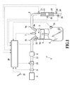
- Fig. 1 is a schematic systematic diagram of an internal combustion engine according to an embodiment of the present invention.
- the internal combustion engine 1 combusts a mixed gas of fuel and air inside a combustion chamber 3 formed in a cylinder block 2 to reciprocate the piston 4 in the combustion chamber to generate power.
- the internal combustion engine 1 is a multi-cylinder engine (only one cylinder is shown) for vehicles, specifically, a spark ignition type engine, more specifically, a gasoline engine.
- the internal combustion engine to which the present invention is applied is not limited to the spark ignition type but may be a compression ignition type, that is, a diesel engine.
- An intake valve Vi that opens and closes an intake port and an exhaust valve Ve that opens and closes an exhaust port are disposed on the cylinder head of each cylinder of the internal combustion engine 1.
- the intake valve Vi and the exhaust valve Ve are opened and closed by a cam shaft (not shown in the drawings).
- an ignition plug 7 is attached to the top of the cylinder head of each cylinder in order to ignite the mixed gas in the combustion chamber 3.
- an injector (fuel injection valve) 12 is disposed on the cylinder head of each cylinder so as to inject fuel directly into the combustion chamber 3.
- the piston 4 is configured so as to be of what is called a dish top surface type with a recess portion 4a formed in the top surface.
- the injector 12 injects fuel toward the recess portion 4a of the piston 4.
- a layer of mixed gas of fuel and air is formed (stratified) near an ignition plug 7 and separately from the surrounding air layer.
- stable stratified combustion is performed.
- the intake port of each cylinder is connected, via a branch pipe for each cylinder, to a surge tank 8 that is an intake air collecting chamber.
- An intake pipe 13 serving as an intake air collecting passage is connected to the upstream side of the surge tank 8.
- An air cleaner 9 is provided at the upstream end of the intake pipe 13.
- An airflow meter 5 detecting the amount of intake air and an electronic control throttle valve 10 are incorporated in the intake pipe 13 and arranged in this order from the upstream side to the downstream side.
- the intake port, the surge tank 8, and the intake pipe 13 form an intake passage.
- each cylinder is connected, via a branch pipe for each cylinder, to an exhaust pipe 6 serving as an exhaust gas collecting passage.
- a three way catalyst 11 capable of simultaneously purifying CO, HC, and NOx in exhaust gas is provided on the upstream side of the exhaust pipe 6.
- An NOx catalyst 16 capable of purifying NOx in the exhaust gas is provided on the downstream side of the exhaust pipe 6.
- the present embodiment uses a CCL (Catalytic Converter Lean) catalyst unit in which the there way catalyst 11 and the NOx catalyst 16 are accommodated in the same casing.
- the three way catalyst 11 and the NOx catalyst 16 may be accommodated in separate casings so as to be individually arranged.
- the three way catalyst 11 is not necessarily essential and may be omitted. For example, in the diesel engine, the three way catalyst is often omitted.
- An air-fuel ratio sensor 17 is installed upstream of the three way catalyst 11 in order to detect the air-fuel ratio (A/F) of the exhaust gas. Furthermore, an NOx sensor detecting the NOx concentration of the exhaust gas, that is, an after-catalyst NOx sensor 18, is installed downstream of the NOx catalyst 16.
- the air-fuel ratio sensor 17 is made up of what is called a wide-range air-fuel ratio sensor.
- the air-fuel ratio sensor 17 can continuously detect the air-fuel ratio over a relatively wide range, and outputs current signals proportional to the air-fuel ratio.
- the air-fuel ratio sensor 17 may be made up of what is called an O 2 sensor providing an output voltage that varies largely at a boundary of a theoretical air-fuel ratio (stoichiometry).
- the above-described ignition plug 7, throttle valve 10, injector 12, and the like are electrically connected to an electronic control unit (hereinafter referred to as an ECU) serving as control means.
- the ECU 20 includes a CPU, a ROM, a RAM, an I/O port, and a storage device (none of these components are shown in the drawings). Furthermore, as shown in FIG.
- the ECU 20 connects not only to the airflow meter 5, air-fuel ratio sensor 17, and after-catalyst NOx sensor 18 described above but also to a crank angle sensor 14 detecting the crank angle of the internal combustion engine 1, an accelerator opening sensor 15 detecting accelerator opening, exhaust temperature sensors installed upstream and downstream, respectively, of the NOx catalyst 16, that is, a before-catalyst exhaust temperature sensor 21 and an after-catalyst exhaust temperature sensor 22, and various other sensors, via A/D converters or the like (not shown in the drawings).
- the ECU 20 controls the ignition plug 7, the throttle valve 10, the injector 12, and the like and thus ignition timing, fuel injection amount, fuel injection timing, throttle opening, and the like so as to obtain desired outputs.
- the before-catalyst exhaust temperature sensor 21 is installed at a position between the three way catalyst 11 and the NOx catalyst 16.
- the after-catalyst NOx sensor 18 adopted includes a heater. The temperature of the after-catalyst NOx sensor 18 is controlled (heat controlled) by the ECU 20. Outputs from the crank angle sensor 14 are used to detect an engine rotation speed Ne.
- the range (window) of the air-fuel ratio within which the three elements can be simultaneously efficiently purified is relatively narrow.
- the air-fuel ratio of the mixed gas is controlled such that the air-fuel ratio of the exhaust gas flowing into the three way catalyst 11 is close to the theoretical air-fuel ratio. This is called stoichiometric control, and the operational aspect of the engine in which stoichiometric control is performed is called a stoichiometric operation.
- the stoichiometric control sets a target air-fuel ratio to be equal to the theoretical air-fuel ratio.
- the amount of fuel injected by the injector 12 or the air-fuel ratio is feedback-controlled so that the air-fuel ratio detected by the air-fuel ratio sensor 17 is equal to the target air-fuel ratio.
- the target air-fuel ratio may be set a value higher than the theoretical air-fuel ratio, that is, a lean value.
- lean burn control a value higher than the theoretical air-fuel ratio
- the operational aspect of the engine in which the lean burn control is performed is called a lean burn operation.
- the fuel injection amount or the air-fuel ratio is feedback-controlled so that the air-fuel ratio detected by the air-fuel ratio sensor 17 is equal to the target air-fuel ratio.
- the air-fuel ratio of the exhaust gas emitted by the engine may have such a lean value that the three way catalyst 11 cannot substantially purify NOx.
- the NOx catalyst 16 is provided downstream of the three way catalyst 11 to purify the NOx having passed through the three way catalyst 11 in the above-described case.
- the NOx catalyst of storage reduction type is composed of a base material made up of an oxide such as alumina Al 2 O 3 , rare metal such as platinum Pt serving as a catalytic component, and an NOx absorbing component; the rare metal and the NOx absorbing component carried on the surface of the base material.
- the NOx absorbing material is made up of one selected from alkali metal such as potassium K, sodium Na, lithium Li, and cesium Cs, alkali earths such as barium Ba and calcium Ca, and rare earths such as lanthanum La and yttrium Y.
- the NOx catalyst of storage reduction type 16 exerts an NOx absorbing and releasing effect such that the catalyst absorbs the NOx in the exhaust gas flowing into the catalyst, in the form of nitrate when the air-fuel ratio of the exhaust gas is leaner than the theoretical air-fuel ratio and such that the catalyst releases the absorbed NOx when the air-fuel ratio of the exhaust gas flowing into the catalyst is equal to or richer than the theoretical air-fuel ratio.
- the exhaust air-fuel ratio is leaner than the theoretical air-fuel ratio.
- the NOx catalyst 16 absorbs NOx from the exhaust gas.
- the NOx catalyst 16 can no longer absorb NOx.
- rich spike control is performed such that the NOx catalyst 16 is temporarily supplied with exhaust gas with an air-fuel ratio equal to or richer than the theoretical air-fuel ratio.
- the target air-fuel ratio is temporarily set equal to or richer than the theoretical air-fuel ratio so that the air-fuel ratio of the mixed gas or the exhaust gas is controlled to a rich value equal to or lower than the theoretical air-fuel ratio.
- the absorbed NOx is released from the NOx catalyst 16 to recover the NOx storing capability of the NOx catalyst 16. This is called NOx recovery.
- a reducing agent supply valve may be separately provided upstream of the NOx catalyst and controllably opened to feed a reducing agent into the exhaust gas.
- the reducing agent has only to generate a reducing component such as carbon hydride HC or carbon monoxide CO in the exhaust gas.
- the possible reducing agent include gas such as hydrogen or carbon monoxide, liquid or gaseous carbon hydride such as propane, propylene, or butane, and liquid fuel such as gasoline, light oil, or kerosene.
- fuel for the engine that is, gasoline
- the fuel is injected from the injector 12 into the combustion chamber 3 during the latter phase of an expansion stroke or during an exhaust stroke so that the exhaust gas contains much unburned fuel.
- the present embodiment detects or estimates the temperature of the NOx catalyst 16 (catalyst bed temperature).
- the temperature of the NOx catalyst 16 can be detected directly by a temperature sensor imbedded in the NOx catalyst.
- the present embodiment estimates the temperature.
- the ECU 20 estimates the catalyst temperature based on a before-catalyst exhaust temperature and an after-catalyst exhaust temperature detected by a before-catalyst exhaust temperature sensor 21 and an after-catalyst exhaust temperature sensor 22, respectively.
- the estimation method is not limited to this example.
- the abnormality diagnosis of the after-catalyst NOx sensor 18 in the present embodiment is generally characterized in that the possible abnormality of the after-catalyst NOx sensor 18 is determined by, under the condition that the NOx catalyst 16 does not substantially absorb the NOx in the exhaust gas, allowing the after-catalyst NOx sensor 18 to detect the after-catalyst NOx concentration and detecting or estimating the before-catalyst NOx concentration on the upstream side of the NOx catalyst, and then comparing the before-catalyst NOx concentration with the after-catalyst NOx concentration.
- the expression "NOx catalyst does not substantially absorb the NOx in the exhaust gas” means that the normal, non-deteriorated NOx catalyst does not substantially absorb the NOx in the exhaust gas.
- the NOx catalyst is normal and is not deteriorated but has its NOx absorbing capability temporarily significantly degraded. This involves a condition in which the NOx absorbing capability of the NOx catalyst is zero.
- the present invention is not limited to this condition.
- the NOx catalyst 16 does not substantially operate.
- the NOx flowing into the NOx catalyst 16 passes through the NOx catalyst 16 and flows further downstream.
- the NOx concentration on the upstream side of the NOx catalyst 16, that is, the before-catalyst NOx concentration is generally equal to the NOx concentration on the downstream side of the NOx catalyst 16, that is, the after-catalyst NOx concentration.
- the after-catalyst NOx sensor 18 can be determined to abnormal.
- the after-catalyst NOx sensor 18 can be determined to be normal.
- the abnormality diagnosis is performed in a condition in which the NOx catalyst does not operate, that is, in a condition similar to that in which no NOx catalyst is present.
- the possible impact of the NOx catalyst on the abnormality diagnosis can be eliminated, ensuring a high diagnosis accuracy.
- the apparatus can avoid the incorrect determination of whether the NOx catalyst or the after-catalyst NOx sensor is abnormal and reliably determine the after-catalyst NOx sensor to be abnormal.
- the present embodiment determines the possible abnormality of the after-catalyst NOx sensor by comparing the after-catalyst NOx concentration and before-catalyst NOx concentration detected under the condition that the catalyst temperature, which is an estimated temperature, is such that at the catalyst temperature, the NOx catalyst 16 does not substantially absorb NOx.
- the NOx catalyst 16 cannot substantially absorb or release NOx unless the temperature of the NOx catalyst 16 falls within the predetermined operative temperature range.
- the NOx catalyst 16 cannot absorb NOx.
- the present embodiment determines the possible abnormality of the after-catalyst NOx sensor by comparing the before-catalyst NOx concentration with the after-catalyst NOx concentration detected when the catalyst temperature is at least either higher or lower than the operative temperature range.
- the situation where the catalyst temperature falls out of the operative temperature range is utilized to perform the abnormality diagnosis of the after-catalyst NOx sensor.
- the lower limit temperature Tcmin of the operative temperature range is, for example, 300°C.
- the upper limit temperature Tcmax of the operative temperature range is, for example, 550°C.
- the possible abnormality of the after-catalyst NOx sensor may be determined by comparing the after-catalyst NOx concentration and before-catalyst NOx concentration detected under the condition that the air-fuel ratio (in the present embodiment, the air-fuel ratio detected by the air-fuel ratio sensor 17) of the exhaust gas flowing into the NOx catalyst 16 is equal to or richer than the theoretical air-fuel ratio.
- the air-fuel ratio of the exhaust gas flowing into the NOx catalyst 16 is equal to or richer than the theoretical air-fuel ratio
- the NOx catalyst 16 can also not release or absorb NOx. Thus, this situation can be utilized to diagnose the after-catalyst NOx sensor for abnormality.
- the possible abnormality of the after-catalyst NOx sensor may be determined by comparing the after-catalyst NOx concentration and before-catalyst NOx concentration detected under the condition that as a result of absorption, the NOx catalyst 16 is saturated with (full of) NOx. Also in this case, the NOx catalyst 16 cannot absorb NOx. Thus, this situation can be utilized to diagnose the after-catalyst NOx sensor for abnormality.
- the before-catalyst NOx concentration is preferably one of the concentration of NOx in the exhaust gas emitted from the combustion chamber 13 of the engine 10 which concentration is estimated based on the operating condition of the engine 10 (this concentration of NOx is hereinafter referred to as a before-catalyst estimated NOx concentration) and the NOx concentration detected by the NOx sensor provided upstream of the NOx catalyst 16, that is, the before-catalyst NOx sensor (see reference numeral 30 in Fig. 4 ) (this concentration is hereinafter referred to as a before-catalyst detected NOx concentration).
- the present embodiment uses the former before-catalyst NOx concentration, that is, the before-catalyst estimated NOx concentration.
- the ECU 20 Based on the detected value of a parameter indicating the operating condition of the engine, the ECU 20 calculates the before-catalyst estimated NOx concentration according to a pre-created map or the like.
- the parameter may be at least one of, for example, an engine rotation speed Ne, an intake air amount Ga, an air-fuel ratio A/F, an exhaust temperature Teg, and a fuel injection amount Q.
- the before-catalyst estimated NOx concentration is calculated according to a predetermined map or the like.
- the actual detected value is used. This may enable a possible estimation error to be inhibited if the data in an NOx concentration estimation map is temporally inappropriate.
- the use of both the former and latter before-catalyst NOx concentrations may enable the diagnosis accuracy to be improved as a result of comparison with the two values.
- the before-catalyst NOx concentration needs to have an accurate value.
- Other sites (the injector and the like) of the engine are diagnosed for abnormality by the ECU 20.
- the before-catalyst estimated NOx concentration can be considered to be accurate. This ensures the accuracy of the before-catalyst estimated NOx concentration and the reliability of the results of abnormality diagnosis of the after-catalyst NOx sensor 18.
- the three way catalyst 11 is located upstream of the NOx catalyst 16.
- the engine is subjected to a lean burn operation to increase the exhaust air-fuel ratio to the degree that the three way catalyst 11 cannot purify NOx, as described below.
- the possible impact of the three way catalyst 11 is inhibited, and the three way catalyst 11 can be considered to be absent.
- NOx emitted by the engine can be considered to pass through the three way catalyst 11 and the NOx catalyst 16 without stopping and reach the after-catalyst NOx sensor 18.
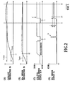
- Fig. 2 shows variation in various values after the start of the engine.
- Fig. 2(A) shows a catalyst temperature Tc estimated by the ECU 20.
- Fig. 2(B) shows the temperature Ts of the after-catalyst NOx sensor 18 (hereinafter sometimes simply referred to as the sensor temperature).
- Fig. 2(C) shows output from the air-fuel ratio sensor 17 (in terms of the value of the air-fuel ratio A/F).
- Fig. 2(D) shows output from the after-catalyst NOx sensor 18 (in terms of the value of the NOx concentration Cr).
- Time t0 is the time when the engine start is completed.
- the temperature Ts of the after-catalyst NOx sensor 18 is detected and controlled by the ECU 20.
- the ECU 20 detects the element impedance of the after-catalyst NOx sensor 18, and controls the heater in the after-catalyst NOx sensor 18 so that the element impedance exhibits a predetermined value obtained while the sensor is active.
- the catalyst temperature Tc and the sensor temperature Ts rise gradually.
- the catalyst temperature Tc exceeds the lower limit temperature Tcmin and enters the operative temperature range (time t1).
- the sensor temperature Ts also exceeds a lower limit temperature Tsmin (for example, about 750°C) and enters the operative temperature range (time t2).
- the sensor temperature Ts is thereafter maintained at a value slightly larger than that of the lower limit temperature Tsmin.
- the air-fuel ratio control shifts from stoichiometric control to lean burn control.
- the air-fuel ratio is maintained at a value (for example, about 16 to 18) larger than that of the theoretical air-fuel ratio (stoichiometry).
- the rich spike control is performed as shown by reference character (a) in Fig. 2(C) .
- the air-fuel ratio of the mixed gas or exhaust gas is controlled to a rich value smaller than that of the theoretical air-fuel ratio.
- the NOx absorbed by the NOx catalyst 16 is released, and detected downstream of the NOx catalyst 16 as shown by reference numeral (b) in Fig. 2D .
- the rich spike is performed before NOx is detected by the after-catalyst NOx sensor 18, that is, before the NOx catalyst 16 becomes full of NOx absorbed.
- the rich spike may be performed after NOx has been detected by the after-catalyst NOx sensor 18, that is, after the NOx catalyst 16 has become full of NOx absorbed.
- the catalyst temperature Tc thereafter rises gradually and exceeds the upper limit temperature Tc max to deviate from the operative temperature range (time t3).
- the present embodiment utilizes this timing to diagnose the after-catalyst NOx sensor 18 for abnormality.
- the rich spike control is performed as shown by reference numeral (c) in Fig. 2C . This is to emit the NOx absorbed by the NOx catalyst 16 before the NOx concentration is detected in order to inhibit the possible impact of the absorbed NOx during the subsequent detection of the NOx concentration. This is, so to speak, a preprocessing rich spike control.
- the apparatus ends the rich spike control to shift to the lean burn control shown by reference character (d) in Fig. 2C .
- the catalyst temperature Tc is higher than an upper limit temperature Tcmax, the NOx catalyst 16 cannot absorb NOx.
- NOx emitted by the engine passes through the three way catalyst 11 and the NOx catalyst 16 without stopping and reaches the after-catalyst NOx sensor 18.
- the NOx concentration Cr detected by the after-catalyst NOx sensor 18 in the above-described case should be almost equal to the before-catalyst estimated NOx concentration Ce estimated based on the operating condition of the engine.
- the after-catalyst NOx concentration Cr detected by the after-catalyst NOx sensor 18 is acquired. Furthermore, the before-catalyst estimated NOx concentration Ce during the same period is acquired. Then, the NOx concentrations are compared.
- the after-catalyst NOx sensor 18 is determined to be normal. In contrast, if the after-catalyst NOx concentration Cr falls out of the predetermined concentration range ⁇ , the after-catalyst NOx sensor 18 is determined to be abnormal. In the illustrated example, the after-catalyst NOx sensor 18 is determined to be normal.
- the catalyst temperature Tc lowers gradually, and at time t5, reaches the upper limit temperature Tcmax or lower to enter the operative temperature range.
- the after-catalyst NOx concentration Cr and the before-catalyst estimated NOx concentration Ce are acquired during any period between the end of the rich spike and the time when the catalyst temperature Tc becomes equal to or lower than the upper limit temperature Tcmax (t5).
- the abnormality diagnosis is performed when the catalyst temperature Tc is higher than the operative temperature range.
- the abnormality diagnosis may be performed when the catalyst temperature Tc is lower than the operative temperature range.
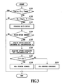
- the illustrated process is executed by the ECU 20.
- a prerequisite for the process is such that lean burn control preventing the three way catalyst 11 from purifying NOx is performed at any time other than during the rich spike control.
- the apparatus determines whether the estimated catalyst temperature Tc falls within the operative temperature range, that is, whether the estimated catalyst temperature Tc is equal to or higher than the lower limit temperature Tcmin and is equal to or lower than the upper limit temperature Tcmax.
- the catalyst temperature Tc falls within the operative temperature range, the present process is ended.
- the catalyst temperature Tc may be controlled so as to fall out of the operative temperature range. For example, making the air-fuel ratio richer raises the catalyst temperature Tc. Making the air-fuel ratio leaner lowers the catalyst temperature Tc.
- step S102 the apparatus determines whether or not the after-catalyst NOx sensor 108 is active, that is, whether or not the temperature Ts of the after-catalyst NOx 18 is higher than the lower limit temperature Tsmin.
- the present process is ended. If the after-catalyst NOx sensor 18 is active, the rich spike control is performed in step S103.
- step S104 the apparatus determines whether or not the rich spike control is ended, that is, a predetermined rich spike end condition is met. If the rich spike control is not ended, that is, if the rich spike control is being performed, the present process is ended. If the rich spike control is ended, the process proceeds to step S105. A step waiting for a predetermined time to pass may be additionally carried out between steps S104 and S105.
- step S105 the value of the before-catalyst estimated NOx concentration Ce estimated based on the operating condition of the engine is acquired. Then, in step S106, the value of the after-catalyst NOx concentration Cr detected by the after-catalyst NOx sensor 18 is acquired.
- step S107 the after-catalyst NOx concentration Cr and the before-catalyst estimated NOx concentration Ce are compared to determine whether or not the concentrations are substantially equal.
- the apparatus determines whether or not the concentration difference ⁇ C is larger than a predetermined value ⁇ Cs.
- the concentration difference ⁇ C is equal to or smaller than the predetermined value ⁇ Cs, the after-catalyst NOx concentration Cr is considered to be substantially equal to the before-catalyst estimated NOx concentration Ce, and in step S108, the after-catalyst NOx sensor 18 is determined to be normal.
- the concentration difference ⁇ C is larger than the predetermined value ⁇ Cs, the after-catalyst NOx concentration Cr is considered to be relatively significantly different from the before-catalyst estimated NOx concentration Ce, and in step S109, the after-catalyst NOx sensor 18 is determined to be abnormal.
- the present process is ended.
- the after-catalyst NOx concentration Cr and the before-catalyst estimated NOx concentration Ce are acquired under the condition (under the temperature condition) that the NOx catalyst 16 cannot substantially absorb NOx. Then, the concentrations acquired are compared to determine the possible abnormality of the after-catalyst NOx sensor 18.
- the abnormality diagnosis can be performed without being affected by the intervening NOx catalyst 16. Consequently, suitable abnormality diagnosis with a high diagnosis accuracy can be achieved.
- the present embodiment also eliminates the need for addition of a specific component such as additional provision of an NOx sensor at the same position as that of the NOx sensor 18. This is economically advantageous and eliminates the need to add complicated control. Of course, the present embodiment is also suitable for onboard diagnosis.
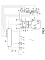
- a before-catalyst NOx sensor 30 is additionally provided in an exhaust passage located upstream of an NOx catalyst 16.
- the before-catalyst NOx sensor 30 detects the NOx concentration on the upstream side of the NOx catalyst (before-catalyst detected NOx concentration).
- the before-catalyst NOx sensor 30 is located upstream of a three way catalyst 11.
- the present invention is not limited to this example.
- the before-catalyst NOx sensor 30 may be located between the three way catalyst 11 and the NOx catalyst 16.
- the present embodiment compares the after-catalyst NOx concentration detected by an after-catalyst NOx sensor 18, the before-catalyst detected NOx concentration detected by the before-catalyst NOx sensor 30, and the before-catalyst estimated NOx concentration estimated based on the operating condition of the engine. Then, based on the result of the comparison, the possible abnormality of the after-catalyst NOx sensor 18 and the before-catalyst NOx sensor 30 is determined in a distinguishable manner.
- the before-catalyst detected Ox concentration is compared with the before-catalyst estimated NOx concentration.
- the before-catalyst NOx sensor 30 directly senses NOx emitted by the engine so that the sensing is not affected by the three way catalyst 11 and the NOx catalyst 16.
- the before-catalyst detected NOx concentration is significantly different from the before-catalyst estimated NOx concentration, the before-catalyst NOx sensor 30 can be determined to abnormal. Since even the abnormality of the before-catalyst NOx sensor 30 can be detected, the scope of the abnormality diagnosis can be expanded.
- the after-catalyst NOx concentration is compared with the before-catalyst detected NOx concentration.
- the after-catalyst NOx concentration and the before-catalyst detected NOx concentration should be almost equal.
- the after-catalyst NOx concentration is significantly different from the before-catalyst detected NOx concentration, the after-catalyst NOx sensor 18 can be determined to be abnormal.
- the after-catalyst NOx concentration may be compared with the before-catalyst estimated NOx concentration.
- Fig. 5 shows a specific process according to the present embodiment. As described above, it is assumed that the illustrated process is executed by the ECU 20 and that a prerequisite for the process is that such lean burn control as prevents the three way catalyst 11 from purifying NOx is performed at any time other than during the rich spike control.
- Steps S201 to S206 are the same as the above-described steps S101 to S106.
- step S207 the value of the before-catalyst detected NOx concentration Cf detected by the before-catalyst NOx sensor 30 is acquired.
- step S208 the before-catalyst detected NOx concentration Cf and the after-catalyst NOx estimated NOx concentration Ce are compared to determine whether or not the concentrations are substantially equal.
- the apparatus determines whether or not the first concentration difference ⁇ C1 is larger than a first predetermined value ⁇ C1s.
- the before-catalyst detected NOx concentration Cf is considered to be relatively significantly different from the before-catalyst estimated NOx concentration Ce.
- the before-catalyst NOx sensor 30 is determined to be abnormal.
- the first concentration difference ⁇ C1 is equal to or smaller than the first predetermined value ⁇ C1s, the before-catalyst detected NOx concentration Cf is considered to be substantially equal to the before-catalyst estimated NOx concentration Ce. The process then proceeds to step S210.
- step S211 the after-catalyst NOx sensor 18 is determined to be abnormal.
- the second concentration difference ⁇ C2 is equal to or smaller than the second predetermined value ⁇ C2s, the after-catalyst NOx concentration Cr is considered to be substantially equal to the before-catalyst detected NOx concentration Cf. The process then proceeds to step S212.
- step S212 both the before-catalyst NOx sensor 30 and the after-catalyst NOx sensor 18 are determined to be normal. The present process is thus completed.
- the embodiments of the present invention have been described. However, the present invention may take other embodiments. For example, the above-described embodiments compare the NOx concentrations based on the difference between the concentrations. However, the present invention is not limited to this aspect, and may compare the NOx concentrations based on the ratio of the concentrations.
- the preprocessing rich spike control (steps S103 and S203) may be performed immediately after the catalyst temperature Tc falls out of the operative temperature range as is the case with the above-described embodiments or immediately before the catalyst temperature Tc falls out of the operative temperature range.
- the preprocessing rich spike control may be omitted.
- the NOx concentration of the exhaust gas may be forcibly controllably varied so as to allow the detected and acquired NOx concentrations to be compared to determine the possible abnormality.
- the present invention is applicable to an NOx sensor provided in an exhaust system of an internal combustion engine.
Landscapes
- Engineering & Computer Science (AREA)
- Chemical & Material Sciences (AREA)
- Combustion & Propulsion (AREA)
- Mechanical Engineering (AREA)
- General Engineering & Computer Science (AREA)
- Chemical Kinetics & Catalysis (AREA)
- Biomedical Technology (AREA)
- Environmental & Geological Engineering (AREA)
- Analytical Chemistry (AREA)
- General Chemical & Material Sciences (AREA)
- Oil, Petroleum & Natural Gas (AREA)
- Health & Medical Sciences (AREA)
- Exhaust Gas After Treatment (AREA)
- Combined Controls Of Internal Combustion Engines (AREA)
- Exhaust Gas Treatment By Means Of Catalyst (AREA)
Applications Claiming Priority (2)
| Application Number | Priority Date | Filing Date | Title |
|---|---|---|---|
| JP2007056043A JP4537417B2 (ja) | 2007-03-06 | 2007-03-06 | NOxセンサの異常診断装置 |
| PCT/JP2008/054555 WO2008108501A1 (ja) | 2007-03-06 | 2008-03-06 | NOxセンサの異常診断装置 |
Publications (3)
| Publication Number | Publication Date |
|---|---|
| EP2119897A1 true EP2119897A1 (de) | 2009-11-18 |
| EP2119897A4 EP2119897A4 (de) | 2012-03-07 |
| EP2119897B1 EP2119897B1 (de) | 2013-09-18 |
Family
ID=39738363
Family Applications (1)
| Application Number | Title | Priority Date | Filing Date |
|---|---|---|---|
| EP08721970.5A Not-in-force EP2119897B1 (de) | 2007-03-06 | 2008-03-06 | Anomalien-diagnosevorrichtung für einen nox-sensor |
Country Status (5)
| Country | Link |
|---|---|
| US (1) | US8091404B2 (de) |
| EP (1) | EP2119897B1 (de) |
| JP (1) | JP4537417B2 (de) |
| CN (1) | CN101646855B (de) |
| WO (1) | WO2008108501A1 (de) |
Cited By (4)
| Publication number | Priority date | Publication date | Assignee | Title |
|---|---|---|---|---|
| WO2011126429A1 (en) * | 2010-04-08 | 2011-10-13 | Scania Cv Ab | Device and method for detecting a state of a sensor in the exhaust system of a motor vehicle |
| AT512760A1 (de) * | 2012-03-21 | 2013-10-15 | Avl List Gmbh | Verfahren zum Betreiben einer Brennkraftmaschine |
| WO2017097557A1 (de) * | 2015-12-11 | 2017-06-15 | Continental Automotive Gmbh | Verfahren, vorrichtung und system zum betreiben eines stickoxidsensors |
| WO2018059834A1 (de) * | 2016-09-29 | 2018-04-05 | Robert Bosch Gmbh | Stationärer erdgasmotor mit wenigstens einem stickoxidsensor |
Families Citing this family (31)
| Publication number | Priority date | Publication date | Assignee | Title |
|---|---|---|---|---|
| JP2009162181A (ja) * | 2008-01-09 | 2009-07-23 | Denso Corp | NOxセンサ診断装置およびそれを用いた排気浄化システム |
| JPWO2010109946A1 (ja) * | 2009-03-23 | 2012-09-27 | ボッシュ株式会社 | Noxセンサの合理性診断装置及び合理性診断方法 |
| JP5500867B2 (ja) * | 2009-04-30 | 2014-05-21 | 日野自動車株式会社 | 排気浄化装置 |
| JP4853548B2 (ja) * | 2009-05-29 | 2012-01-11 | 株式会社デンソー | 排気センサ診断装置 |
| WO2010151690A2 (en) * | 2009-06-24 | 2010-12-29 | Cummins Ip, Inc. | APPARATUS, SYSTEM, AND METHOD FOR ESTIMATING DETERIORATION OF A NOx SENSOR RESPONSE RATE |
| JP4816773B2 (ja) * | 2009-07-16 | 2011-11-16 | 株式会社デンソー | 排気成分濃度センサの応答性検出装置 |
| US8683856B2 (en) * | 2010-04-23 | 2014-04-01 | Toyota Jidosha Kabushiki Kaisha | Catalyst abnormality diagnosis apparatus |
| JP5533235B2 (ja) * | 2010-05-17 | 2014-06-25 | いすゞ自動車株式会社 | NOxセンサ診断装置及びSCRシステム |
| EP2573370A4 (de) * | 2010-05-17 | 2018-02-21 | Toyota Jidosha Kabushiki Kaisha | Steuerungsvorrichtung für einen verbrennungsmotor |
| JP5789925B2 (ja) * | 2010-07-08 | 2015-10-07 | いすゞ自動車株式会社 | NOxセンサ診断装置及びSCRシステム |
| JP2012082710A (ja) * | 2010-10-07 | 2012-04-26 | Toyota Motor Corp | Noxセンサの劣化検出システム |
| JP5831162B2 (ja) * | 2011-11-18 | 2015-12-09 | いすゞ自動車株式会社 | NOxセンサの異常診断方法、NOxセンサの異常診断システム、及び内燃機関 |
| JP5790545B2 (ja) * | 2012-03-05 | 2015-10-07 | 三菱自動車工業株式会社 | 触媒診断装置及び触媒診断方法 |
| JP6037037B2 (ja) * | 2013-09-25 | 2016-11-30 | トヨタ自動車株式会社 | センサの異常診断装置 |
| JP6036772B2 (ja) * | 2013-09-25 | 2016-11-30 | トヨタ自動車株式会社 | 内燃機関の制御装置 |
| US9562486B2 (en) * | 2014-10-24 | 2017-02-07 | Toyota Jidosha Kabushiki Kaisha | Control device for internal combustion engine |
| CN105653071B (zh) * | 2015-12-28 | 2018-12-18 | 联想(北京)有限公司 | 一种信息处理方法和电子设备 |
| DE102016200721A1 (de) * | 2016-01-20 | 2017-07-20 | Robert Bosch Gmbh | Verfahren zur Überwachung von NOx-Sensoren |
| JP7169826B2 (ja) * | 2018-09-21 | 2022-11-11 | 日本碍子株式会社 | 触媒劣化診断システムおよび触媒劣化診断方法 |
| JP2020060120A (ja) * | 2018-10-09 | 2020-04-16 | 日本碍子株式会社 | 触媒の劣化診断装置及び触媒の劣化診断方法 |
| KR102527191B1 (ko) * | 2018-11-20 | 2023-05-02 | 에이치에스디엔진 주식회사 | 선택적 촉매 환원 시스템 |
| CN110631835B (zh) * | 2019-09-25 | 2021-07-09 | 潍坊内燃机质量检验中心有限公司 | 增压压力可信性检测方法及设备 |
| CN111044684A (zh) * | 2019-12-30 | 2020-04-21 | 潍柴动力股份有限公司 | 氮氧传感器篡改的判断方法及设备 |
| US11828210B2 (en) | 2020-08-20 | 2023-11-28 | Denso International America, Inc. | Diagnostic systems and methods of vehicles using olfaction |
| US11760169B2 (en) | 2020-08-20 | 2023-09-19 | Denso International America, Inc. | Particulate control systems and methods for olfaction sensors |
| US11760170B2 (en) | 2020-08-20 | 2023-09-19 | Denso International America, Inc. | Olfaction sensor preservation systems and methods |
| US11932080B2 (en) | 2020-08-20 | 2024-03-19 | Denso International America, Inc. | Diagnostic and recirculation control systems and methods |
| US11813926B2 (en) | 2020-08-20 | 2023-11-14 | Denso International America, Inc. | Binding agent and olfaction sensor |
| US11636870B2 (en) | 2020-08-20 | 2023-04-25 | Denso International America, Inc. | Smoking cessation systems and methods |
| US11881093B2 (en) | 2020-08-20 | 2024-01-23 | Denso International America, Inc. | Systems and methods for identifying smoking in vehicles |
| EP4080024B1 (de) * | 2021-04-22 | 2024-05-29 | Volvo Truck Corporation | Verfahren zur erkennung einer sensoranomalie |
Citations (3)
| Publication number | Priority date | Publication date | Assignee | Title |
|---|---|---|---|---|
| DE10049685A1 (de) * | 2000-10-07 | 2002-04-11 | Volkswagen Ag | Verfahren und Vorrichtung zur Eigendiagnose eines NOX-Sensors |
| US20030192305A1 (en) * | 2001-09-28 | 2003-10-16 | Hitachi, Ltd. | Controller of compression-ignition engine |
| FR2852395A1 (fr) * | 2003-03-13 | 2004-09-17 | Bosch Gmbh Robert | Procede de diagnostic d'un detecteur nox |
Family Cites Families (11)
| Publication number | Priority date | Publication date | Assignee | Title |
|---|---|---|---|---|
| JPH0472446A (ja) * | 1990-07-13 | 1992-03-06 | Nippondenso Co Ltd | 内燃機関のアクセル操作量検出装置 |
| DE19828929A1 (de) * | 1998-06-29 | 2000-01-05 | Siemens Ag | Verfahren zur Überprüfung des Dynamikverhaltens eines Meßaufnehmers im Abgastrakt einer Brennkraftmaschine |
| DE19945374A1 (de) * | 1999-09-22 | 2001-03-29 | Volkswagen Ag | Verfahren zur Funktionsüberwachung eines in einem Abgaskanal einer Verbrennungskraftmaschine angeordneten NO¶x¶-Sensors |
| JP2002047979A (ja) * | 2000-08-03 | 2002-02-15 | Hitachi Ltd | エンジンの制御装置 |
| JP2003120399A (ja) | 2001-10-09 | 2003-04-23 | Toyota Motor Corp | NOxセンサ異常検出装置 |
| JP2003120339A (ja) | 2001-10-10 | 2003-04-23 | Toyota Motor Corp | アクセル反力制御装置 |
| JP3873904B2 (ja) * | 2003-02-26 | 2007-01-31 | 日産自動車株式会社 | 内燃機関の排気浄化装置 |
| JP4273306B2 (ja) * | 2003-03-05 | 2009-06-03 | 三菱ふそうトラック・バス株式会社 | NOxセンサの異常判定装置 |
| DE102004051747A1 (de) * | 2004-10-23 | 2006-04-27 | Robert Bosch Gmbh | Verfahren zum Betreiben einer Brennkraftmaschine und Vorrichtung zur Durchführung des Verfahrens |
| JP2006348778A (ja) * | 2005-06-14 | 2006-12-28 | Denso Corp | 圧力センサの異常診断装置 |
| FR2906312B1 (fr) * | 2006-09-27 | 2016-04-15 | Bosch Gmbh Robert | Procede de diagnostic d'un capteur de gaz d'echappement equipant un moteur a combustion interne et dispositif pour sa mise en oeuvre. |
-
2007
- 2007-03-06 JP JP2007056043A patent/JP4537417B2/ja not_active Expired - Fee Related
-
2008
- 2008-03-06 CN CN2008800072572A patent/CN101646855B/zh not_active Expired - Fee Related
- 2008-03-06 EP EP08721970.5A patent/EP2119897B1/de not_active Not-in-force
- 2008-03-06 WO PCT/JP2008/054555 patent/WO2008108501A1/ja active Application Filing
- 2008-03-06 US US12/449,892 patent/US8091404B2/en not_active Expired - Fee Related
Patent Citations (3)
| Publication number | Priority date | Publication date | Assignee | Title |
|---|---|---|---|---|
| DE10049685A1 (de) * | 2000-10-07 | 2002-04-11 | Volkswagen Ag | Verfahren und Vorrichtung zur Eigendiagnose eines NOX-Sensors |
| US20030192305A1 (en) * | 2001-09-28 | 2003-10-16 | Hitachi, Ltd. | Controller of compression-ignition engine |
| FR2852395A1 (fr) * | 2003-03-13 | 2004-09-17 | Bosch Gmbh Robert | Procede de diagnostic d'un detecteur nox |
Non-Patent Citations (1)
| Title |
|---|
| See also references of WO2008108501A1 * |
Cited By (7)
| Publication number | Priority date | Publication date | Assignee | Title |
|---|---|---|---|---|
| WO2011126429A1 (en) * | 2010-04-08 | 2011-10-13 | Scania Cv Ab | Device and method for detecting a state of a sensor in the exhaust system of a motor vehicle |
| EP2556227A4 (de) * | 2010-04-08 | 2018-03-21 | Scania CV AB | Vorrichtung und verfahren zur erkennung des status eines sensors im abgassystem eines motorfahrzeugs |
| AT512760A1 (de) * | 2012-03-21 | 2013-10-15 | Avl List Gmbh | Verfahren zum Betreiben einer Brennkraftmaschine |
| AT512760B1 (de) * | 2012-03-21 | 2014-05-15 | Avl List Gmbh | Verfahren zum Betreiben einer Brennkraftmaschine |
| WO2017097557A1 (de) * | 2015-12-11 | 2017-06-15 | Continental Automotive Gmbh | Verfahren, vorrichtung und system zum betreiben eines stickoxidsensors |
| US10914220B2 (en) | 2015-12-11 | 2021-02-09 | Vitesco Technologies GmbH | Method, device, and system for operating a nitrogen oxide sensor |
| WO2018059834A1 (de) * | 2016-09-29 | 2018-04-05 | Robert Bosch Gmbh | Stationärer erdgasmotor mit wenigstens einem stickoxidsensor |
Also Published As
| Publication number | Publication date |
|---|---|
| EP2119897B1 (de) | 2013-09-18 |
| US8091404B2 (en) | 2012-01-10 |
| CN101646855B (zh) | 2013-01-16 |
| JP4537417B2 (ja) | 2010-09-01 |
| JP2008215260A (ja) | 2008-09-18 |
| EP2119897A4 (de) | 2012-03-07 |
| WO2008108501A1 (ja) | 2008-09-12 |
| US20100024520A1 (en) | 2010-02-04 |
| CN101646855A (zh) | 2010-02-10 |
Similar Documents
| Publication | Publication Date | Title |
|---|---|---|
| EP2119897B1 (de) | Anomalien-diagnosevorrichtung für einen nox-sensor | |
| EP2119882B1 (de) | Vorrichtung zur diagnose des alterungszustandes eines nox-katalysators | |
| EP2188506B1 (de) | Nox-sensor-fehlfunktionsdiagnosevorrichtung und fehlfunktionsdiagnoseverfahren | |
| US20090199543A1 (en) | Catalyst monitoring system and monitoring method | |
| US6990800B2 (en) | Diesel aftertreatment systems | |
| US9784721B2 (en) | Determination of a degree of aging of an oxidizing catalytic converter | |
| JP5062529B2 (ja) | 触媒の劣化を診断するための装置及び方法 | |
| US20090094963A1 (en) | Exhaust particulate matter measuring apparatus | |
| JP6059272B2 (ja) | 触媒劣化診断装置 | |
| JP2008215261A (ja) | 触媒の劣化診断装置及び劣化診断方法 | |
| EP2362082A1 (de) | Motorsystemsteuervorrichtung | |
| US11492952B2 (en) | Catalyst degradation detection apparatus | |
| JP2009138604A (ja) | 内燃機関の触媒劣化診断装置 | |
| US20120023913A1 (en) | Catalyst abnormality diagnosis apparatus | |
| JP4867909B2 (ja) | NOx触媒の劣化診断装置 | |
| JP5260978B2 (ja) | 燃料性状判定装置及びこれを備えた触媒劣化診断装置 | |
| JP5494571B2 (ja) | 燃料性状判定装置及びこれを備えた触媒異常診断装置 | |
| JP2009121414A (ja) | 内燃機関の触媒劣化診断装置 | |
| Sawada et al. | Abnormality diagnosis apparatus for NO x sensor | |
| JP2009138605A (ja) | NOx触媒の劣化診断装置 | |
| WO2013157048A1 (ja) | 触媒異常診断装置 | |
| JP2004060518A (ja) | 内燃機関の排気浄化装置 | |
| JP2017129037A (ja) | NOx吸蔵還元型触媒の異常診断装置 | |
| JP2019157671A (ja) | 排気浄化触媒の異常検出装置 | |
| JP2013024118A (ja) | 触媒異常診断装置 |
Legal Events
| Date | Code | Title | Description |
|---|---|---|---|
| PUAI | Public reference made under article 153(3) epc to a published international application that has entered the european phase |
Free format text: ORIGINAL CODE: 0009012 |
|
| 17P | Request for examination filed |
Effective date: 20090903 |
|
| AK | Designated contracting states |
Kind code of ref document: A1 Designated state(s): AT BE BG CH CY CZ DE DK EE ES FI FR GB GR HR HU IE IS IT LI LT LU LV MC MT NL NO PL PT RO SE SI SK TR |
|
| DAX | Request for extension of the european patent (deleted) | ||
| A4 | Supplementary search report drawn up and despatched |
Effective date: 20120202 |
|
| RIC1 | Information provided on ipc code assigned before grant |
Ipc: F01N 3/18 20060101ALI20120127BHEP Ipc: F02D 45/00 20060101AFI20120127BHEP Ipc: F02D 41/22 20060101ALI20120127BHEP Ipc: F01N 3/00 20060101ALI20120127BHEP Ipc: B01D 53/94 20060101ALI20120127BHEP Ipc: F02D 41/14 20060101ALI20120127BHEP Ipc: F01N 3/08 20060101ALI20120127BHEP Ipc: F01N 3/28 20060101ALI20120127BHEP |
|
| RIC1 | Information provided on ipc code assigned before grant |
Ipc: B01D 53/94 20060101ALI20120814BHEP Ipc: F01N 3/00 20060101ALI20120814BHEP Ipc: F01N 3/28 20060101ALI20120814BHEP Ipc: F01N 3/18 20060101ALI20120814BHEP Ipc: F02D 45/00 20060101AFI20120814BHEP Ipc: F02D 41/14 20060101ALI20120814BHEP Ipc: F01N 3/08 20060101ALI20120814BHEP Ipc: F02D 41/22 20060101ALI20120814BHEP |
|
| RIC1 | Information provided on ipc code assigned before grant |
Ipc: F01N 3/28 20060101ALI20120924BHEP Ipc: F01N 3/00 20060101ALI20120924BHEP Ipc: F01N 3/18 20060101ALI20120924BHEP Ipc: F02D 41/14 20060101ALI20120924BHEP Ipc: B01D 53/94 20060101ALI20120924BHEP Ipc: F01N 3/08 20060101ALI20120924BHEP Ipc: F02D 45/00 20060101AFI20120924BHEP Ipc: F02D 41/22 20060101ALI20120924BHEP |
|
| RAP1 | Party data changed (applicant data changed or rights of an application transferred) |
Owner name: TOYOTA JIDOSHA KABUSHIKI KAISHA Owner name: DENSO CORPORATION |
|
| GRAJ | Information related to disapproval of communication of intention to grant by the applicant or resumption of examination proceedings by the epo deleted |
Free format text: ORIGINAL CODE: EPIDOSDIGR1 |
|
| GRAP | Despatch of communication of intention to grant a patent |
Free format text: ORIGINAL CODE: EPIDOSNIGR1 |
|
| GRAP | Despatch of communication of intention to grant a patent |
Free format text: ORIGINAL CODE: EPIDOSNIGR1 |
|
| INTG | Intention to grant announced |
Effective date: 20130328 |
|
| GRAS | Grant fee paid |
Free format text: ORIGINAL CODE: EPIDOSNIGR3 |
|
| GRAA | (expected) grant |
Free format text: ORIGINAL CODE: 0009210 |
|
| AK | Designated contracting states |
Kind code of ref document: B1 Designated state(s): AT BE BG CH CY CZ DE DK EE ES FI FR GB GR HR HU IE IS IT LI LT LU LV MC MT NL NO PL PT RO SE SI SK TR |
|
| REG | Reference to a national code |
Ref country code: GB Ref legal event code: FG4D |
|
| REG | Reference to a national code |
Ref country code: CH Ref legal event code: EP |
|
| REG | Reference to a national code |
Ref country code: IE Ref legal event code: FG4D |
|
| REG | Reference to a national code |
Ref country code: AT Ref legal event code: REF Ref document number: 632932 Country of ref document: AT Kind code of ref document: T Effective date: 20131015 |
|
| REG | Reference to a national code |
Ref country code: DE Ref legal event code: R096 Ref document number: 602008027628 Country of ref document: DE Effective date: 20131114 |
|
| PG25 | Lapsed in a contracting state [announced via postgrant information from national office to epo] |
Ref country code: HR Free format text: LAPSE BECAUSE OF FAILURE TO SUBMIT A TRANSLATION OF THE DESCRIPTION OR TO PAY THE FEE WITHIN THE PRESCRIBED TIME-LIMIT Effective date: 20130918 Ref country code: CY Free format text: LAPSE BECAUSE OF FAILURE TO SUBMIT A TRANSLATION OF THE DESCRIPTION OR TO PAY THE FEE WITHIN THE PRESCRIBED TIME-LIMIT Effective date: 20130814 Ref country code: NO Free format text: LAPSE BECAUSE OF FAILURE TO SUBMIT A TRANSLATION OF THE DESCRIPTION OR TO PAY THE FEE WITHIN THE PRESCRIBED TIME-LIMIT Effective date: 20131218 Ref country code: SE Free format text: LAPSE BECAUSE OF FAILURE TO SUBMIT A TRANSLATION OF THE DESCRIPTION OR TO PAY THE FEE WITHIN THE PRESCRIBED TIME-LIMIT Effective date: 20130918 Ref country code: LT Free format text: LAPSE BECAUSE OF FAILURE TO SUBMIT A TRANSLATION OF THE DESCRIPTION OR TO PAY THE FEE WITHIN THE PRESCRIBED TIME-LIMIT Effective date: 20130918 |
|
| REG | Reference to a national code |
Ref country code: NL Ref legal event code: VDEP Effective date: 20130918 |
|
| REG | Reference to a national code |
Ref country code: AT Ref legal event code: MK05 Ref document number: 632932 Country of ref document: AT Kind code of ref document: T Effective date: 20130918 |
|
| REG | Reference to a national code |
Ref country code: LT Ref legal event code: MG4D |
|
| PG25 | Lapsed in a contracting state [announced via postgrant information from national office to epo] |
Ref country code: LV Free format text: LAPSE BECAUSE OF FAILURE TO SUBMIT A TRANSLATION OF THE DESCRIPTION OR TO PAY THE FEE WITHIN THE PRESCRIBED TIME-LIMIT Effective date: 20130918 Ref country code: GR Free format text: LAPSE BECAUSE OF FAILURE TO SUBMIT A TRANSLATION OF THE DESCRIPTION OR TO PAY THE FEE WITHIN THE PRESCRIBED TIME-LIMIT Effective date: 20131219 Ref country code: FI Free format text: LAPSE BECAUSE OF FAILURE TO SUBMIT A TRANSLATION OF THE DESCRIPTION OR TO PAY THE FEE WITHIN THE PRESCRIBED TIME-LIMIT Effective date: 20130918 Ref country code: SI Free format text: LAPSE BECAUSE OF FAILURE TO SUBMIT A TRANSLATION OF THE DESCRIPTION OR TO PAY THE FEE WITHIN THE PRESCRIBED TIME-LIMIT Effective date: 20130918 |
|
| PG25 | Lapsed in a contracting state [announced via postgrant information from national office to epo] |
Ref country code: CY Free format text: LAPSE BECAUSE OF FAILURE TO SUBMIT A TRANSLATION OF THE DESCRIPTION OR TO PAY THE FEE WITHIN THE PRESCRIBED TIME-LIMIT Effective date: 20130918 Ref country code: BE Free format text: LAPSE BECAUSE OF FAILURE TO SUBMIT A TRANSLATION OF THE DESCRIPTION OR TO PAY THE FEE WITHIN THE PRESCRIBED TIME-LIMIT Effective date: 20130918 |
|
| PG25 | Lapsed in a contracting state [announced via postgrant information from national office to epo] |
Ref country code: IS Free format text: LAPSE BECAUSE OF FAILURE TO SUBMIT A TRANSLATION OF THE DESCRIPTION OR TO PAY THE FEE WITHIN THE PRESCRIBED TIME-LIMIT Effective date: 20140118 Ref country code: EE Free format text: LAPSE BECAUSE OF FAILURE TO SUBMIT A TRANSLATION OF THE DESCRIPTION OR TO PAY THE FEE WITHIN THE PRESCRIBED TIME-LIMIT Effective date: 20130918 Ref country code: RO Free format text: LAPSE BECAUSE OF FAILURE TO SUBMIT A TRANSLATION OF THE DESCRIPTION OR TO PAY THE FEE WITHIN THE PRESCRIBED TIME-LIMIT Effective date: 20130918 Ref country code: NL Free format text: LAPSE BECAUSE OF FAILURE TO SUBMIT A TRANSLATION OF THE DESCRIPTION OR TO PAY THE FEE WITHIN THE PRESCRIBED TIME-LIMIT Effective date: 20130918 Ref country code: SK Free format text: LAPSE BECAUSE OF FAILURE TO SUBMIT A TRANSLATION OF THE DESCRIPTION OR TO PAY THE FEE WITHIN THE PRESCRIBED TIME-LIMIT Effective date: 20130918 Ref country code: CZ Free format text: LAPSE BECAUSE OF FAILURE TO SUBMIT A TRANSLATION OF THE DESCRIPTION OR TO PAY THE FEE WITHIN THE PRESCRIBED TIME-LIMIT Effective date: 20130918 |
|
| PG25 | Lapsed in a contracting state [announced via postgrant information from national office to epo] |
Ref country code: ES Free format text: LAPSE BECAUSE OF FAILURE TO SUBMIT A TRANSLATION OF THE DESCRIPTION OR TO PAY THE FEE WITHIN THE PRESCRIBED TIME-LIMIT Effective date: 20130918 Ref country code: PL Free format text: LAPSE BECAUSE OF FAILURE TO SUBMIT A TRANSLATION OF THE DESCRIPTION OR TO PAY THE FEE WITHIN THE PRESCRIBED TIME-LIMIT Effective date: 20130918 Ref country code: AT Free format text: LAPSE BECAUSE OF FAILURE TO SUBMIT A TRANSLATION OF THE DESCRIPTION OR TO PAY THE FEE WITHIN THE PRESCRIBED TIME-LIMIT Effective date: 20130918 |
|
| REG | Reference to a national code |
Ref country code: DE Ref legal event code: R097 Ref document number: 602008027628 Country of ref document: DE |
|
| PG25 | Lapsed in a contracting state [announced via postgrant information from national office to epo] |
Ref country code: PT Free format text: LAPSE BECAUSE OF FAILURE TO SUBMIT A TRANSLATION OF THE DESCRIPTION OR TO PAY THE FEE WITHIN THE PRESCRIBED TIME-LIMIT Effective date: 20140120 |
|
| PLBE | No opposition filed within time limit |
Free format text: ORIGINAL CODE: 0009261 |
|
| STAA | Information on the status of an ep patent application or granted ep patent |
Free format text: STATUS: NO OPPOSITION FILED WITHIN TIME LIMIT |
|
| 26N | No opposition filed |
Effective date: 20140619 |
|
| PG25 | Lapsed in a contracting state [announced via postgrant information from national office to epo] |
Ref country code: IT Free format text: LAPSE BECAUSE OF FAILURE TO SUBMIT A TRANSLATION OF THE DESCRIPTION OR TO PAY THE FEE WITHIN THE PRESCRIBED TIME-LIMIT Effective date: 20130918 |
|
| PG25 | Lapsed in a contracting state [announced via postgrant information from national office to epo] |
Ref country code: DK Free format text: LAPSE BECAUSE OF FAILURE TO SUBMIT A TRANSLATION OF THE DESCRIPTION OR TO PAY THE FEE WITHIN THE PRESCRIBED TIME-LIMIT Effective date: 20130918 |
|
| REG | Reference to a national code |
Ref country code: DE Ref legal event code: R097 Ref document number: 602008027628 Country of ref document: DE Effective date: 20140619 |
|
| PG25 | Lapsed in a contracting state [announced via postgrant information from national office to epo] |
Ref country code: LU Free format text: LAPSE BECAUSE OF FAILURE TO SUBMIT A TRANSLATION OF THE DESCRIPTION OR TO PAY THE FEE WITHIN THE PRESCRIBED TIME-LIMIT Effective date: 20140306 |
|
| REG | Reference to a national code |
Ref country code: CH Ref legal event code: PL |
|
| GBPC | Gb: european patent ceased through non-payment of renewal fee |
Effective date: 20140306 |
|
| REG | Reference to a national code |
Ref country code: FR Ref legal event code: ST Effective date: 20141128 |
|
| REG | Reference to a national code |
Ref country code: IE Ref legal event code: MM4A |
|
| PG25 | Lapsed in a contracting state [announced via postgrant information from national office to epo] |
Ref country code: FR Free format text: LAPSE BECAUSE OF NON-PAYMENT OF DUE FEES Effective date: 20140331 Ref country code: LI Free format text: LAPSE BECAUSE OF NON-PAYMENT OF DUE FEES Effective date: 20140331 Ref country code: IE Free format text: LAPSE BECAUSE OF NON-PAYMENT OF DUE FEES Effective date: 20140306 Ref country code: CH Free format text: LAPSE BECAUSE OF NON-PAYMENT OF DUE FEES Effective date: 20140331 Ref country code: GB Free format text: LAPSE BECAUSE OF NON-PAYMENT OF DUE FEES Effective date: 20140306 |
|
| REG | Reference to a national code |
Ref country code: DE Ref legal event code: R084 Ref document number: 602008027628 Country of ref document: DE |
|
| PG25 | Lapsed in a contracting state [announced via postgrant information from national office to epo] |
Ref country code: MT Free format text: LAPSE BECAUSE OF FAILURE TO SUBMIT A TRANSLATION OF THE DESCRIPTION OR TO PAY THE FEE WITHIN THE PRESCRIBED TIME-LIMIT Effective date: 20130918 |
|
| PG25 | Lapsed in a contracting state [announced via postgrant information from national office to epo] |
Ref country code: BG Free format text: LAPSE BECAUSE OF FAILURE TO SUBMIT A TRANSLATION OF THE DESCRIPTION OR TO PAY THE FEE WITHIN THE PRESCRIBED TIME-LIMIT Effective date: 20130918 Ref country code: MC Free format text: LAPSE BECAUSE OF FAILURE TO SUBMIT A TRANSLATION OF THE DESCRIPTION OR TO PAY THE FEE WITHIN THE PRESCRIBED TIME-LIMIT Effective date: 20130918 |
|
| PG25 | Lapsed in a contracting state [announced via postgrant information from national office to epo] |
Ref country code: HU Free format text: LAPSE BECAUSE OF FAILURE TO SUBMIT A TRANSLATION OF THE DESCRIPTION OR TO PAY THE FEE WITHIN THE PRESCRIBED TIME-LIMIT; INVALID AB INITIO Effective date: 20080306 Ref country code: TR Free format text: LAPSE BECAUSE OF FAILURE TO SUBMIT A TRANSLATION OF THE DESCRIPTION OR TO PAY THE FEE WITHIN THE PRESCRIBED TIME-LIMIT Effective date: 20130918 |
|
| PGFP | Annual fee paid to national office [announced via postgrant information from national office to epo] |
Ref country code: DE Payment date: 20200225 Year of fee payment: 13 |
|
| REG | Reference to a national code |
Ref country code: DE Ref legal event code: R119 Ref document number: 602008027628 Country of ref document: DE |
|
| PG25 | Lapsed in a contracting state [announced via postgrant information from national office to epo] |
Ref country code: DE Free format text: LAPSE BECAUSE OF NON-PAYMENT OF DUE FEES Effective date: 20211001 |