EP2117796B1 - Verfahren und vorrichtung zur aufbereitung eines materials - Google Patents
Verfahren und vorrichtung zur aufbereitung eines materials Download PDFInfo
- Publication number
- EP2117796B1 EP2117796B1 EP20080706015 EP08706015A EP2117796B1 EP 2117796 B1 EP2117796 B1 EP 2117796B1 EP 20080706015 EP20080706015 EP 20080706015 EP 08706015 A EP08706015 A EP 08706015A EP 2117796 B1 EP2117796 B1 EP 2117796B1
- Authority
- EP
- European Patent Office
- Prior art keywords
- gas
- receiving container
- mixing
- supply means
- gas supply
- Prior art date
- Legal status (The legal status is an assumption and is not a legal conclusion. Google has not performed a legal analysis and makes no representation as to the accuracy of the status listed.)
- Active
Links
- 239000000463 material Substances 0.000 title claims abstract description 149
- 238000000034 method Methods 0.000 title claims abstract description 17
- 230000008569 process Effects 0.000 title claims abstract description 13
- 239000007789 gas Substances 0.000 claims abstract description 167
- 238000002156 mixing Methods 0.000 claims abstract description 89
- 239000000126 substance Substances 0.000 claims abstract description 30
- 239000002245 particle Substances 0.000 claims abstract description 15
- 229920006395 saturated elastomer Polymers 0.000 claims abstract description 6
- 239000011261 inert gas Substances 0.000 claims abstract 2
- 239000004033 plastic Substances 0.000 claims description 35
- 230000002452 interceptive effect Effects 0.000 claims description 13
- 238000012545 processing Methods 0.000 claims description 10
- XLYOFNOQVPJJNP-UHFFFAOYSA-N water Chemical compound O XLYOFNOQVPJJNP-UHFFFAOYSA-N 0.000 claims description 8
- 238000001035 drying Methods 0.000 claims description 7
- 238000011144 upstream manufacturing Methods 0.000 claims description 6
- 238000010438 heat treatment Methods 0.000 claims description 5
- 238000011049 filling Methods 0.000 claims description 2
- 238000007599 discharging Methods 0.000 claims 11
- 238000009434 installation Methods 0.000 claims 4
- 238000005086 pumping Methods 0.000 claims 3
- 239000002861 polymer material Substances 0.000 claims 2
- 239000008188 pellet Substances 0.000 claims 1
- 239000012634 fragment Substances 0.000 abstract 1
- 239000012535 impurity Substances 0.000 description 10
- 230000000694 effects Effects 0.000 description 5
- 239000000356 contaminant Substances 0.000 description 4
- 238000010276 construction Methods 0.000 description 3
- 239000002826 coolant Substances 0.000 description 3
- 230000002349 favourable effect Effects 0.000 description 3
- 239000012530 fluid Substances 0.000 description 3
- 239000000203 mixture Substances 0.000 description 3
- 230000015572 biosynthetic process Effects 0.000 description 2
- 238000004891 communication Methods 0.000 description 2
- 150000001875 compounds Chemical class 0.000 description 2
- 238000013461 design Methods 0.000 description 2
- 238000002474 experimental method Methods 0.000 description 2
- 238000000605 extraction Methods 0.000 description 2
- 238000002347 injection Methods 0.000 description 2
- 239000007924 injection Substances 0.000 description 2
- 239000011159 matrix material Substances 0.000 description 2
- 238000004886 process control Methods 0.000 description 2
- 229920001169 thermoplastic Polymers 0.000 description 2
- 239000004416 thermosoftening plastic Substances 0.000 description 2
- 238000005406 washing Methods 0.000 description 2
- 230000009471 action Effects 0.000 description 1
- 230000002411 adverse Effects 0.000 description 1
- 238000003776 cleavage reaction Methods 0.000 description 1
- 238000000576 coating method Methods 0.000 description 1
- 238000004040 coloring Methods 0.000 description 1
- 230000006835 compression Effects 0.000 description 1
- 238000007906 compression Methods 0.000 description 1
- 238000009833 condensation Methods 0.000 description 1
- 230000005494 condensation Effects 0.000 description 1
- 238000001816 cooling Methods 0.000 description 1
- 238000007872 degassing Methods 0.000 description 1
- 230000001419 dependent effect Effects 0.000 description 1
- 239000000428 dust Substances 0.000 description 1
- 238000001704 evaporation Methods 0.000 description 1
- 230000008020 evaporation Effects 0.000 description 1
- 239000000835 fiber Substances 0.000 description 1
- 239000008187 granular material Substances 0.000 description 1
- 238000007726 management method Methods 0.000 description 1
- 239000000178 monomer Substances 0.000 description 1
- 239000006259 organic additive Substances 0.000 description 1
- 238000013021 overheating Methods 0.000 description 1
- JTJMJGYZQZDUJJ-UHFFFAOYSA-N phencyclidine Chemical class C1CCCCN1C1(C=2C=CC=CC=2)CCCCC1 JTJMJGYZQZDUJJ-UHFFFAOYSA-N 0.000 description 1
- 239000004014 plasticizer Substances 0.000 description 1
- 229920000098 polyolefin Polymers 0.000 description 1
- 238000002360 preparation method Methods 0.000 description 1
- 238000007639 printing Methods 0.000 description 1
- 238000004064 recycling Methods 0.000 description 1
- 230000009467 reduction Effects 0.000 description 1
- 230000007017 scission Effects 0.000 description 1
- 238000000926 separation method Methods 0.000 description 1
- 239000002689 soil Substances 0.000 description 1
- 239000007787 solid Substances 0.000 description 1
- 230000003319 supportive effect Effects 0.000 description 1
- 230000009044 synergistic interaction Effects 0.000 description 1
- 230000003685 thermal hair damage Effects 0.000 description 1
- 239000003039 volatile agent Substances 0.000 description 1
- 239000001993 wax Substances 0.000 description 1
- 238000010626 work up procedure Methods 0.000 description 1
Images

Classifications
-
- B—PERFORMING OPERATIONS; TRANSPORTING
- B02—CRUSHING, PULVERISING, OR DISINTEGRATING; PREPARATORY TREATMENT OF GRAIN FOR MILLING
- B02C—CRUSHING, PULVERISING, OR DISINTEGRATING IN GENERAL; MILLING GRAIN
- B02C18/00—Disintegrating by knives or other cutting or tearing members which chop material into fragments
- B02C18/06—Disintegrating by knives or other cutting or tearing members which chop material into fragments with rotating knives
- B02C18/08—Disintegrating by knives or other cutting or tearing members which chop material into fragments with rotating knives within vertical containers
-
- B—PERFORMING OPERATIONS; TRANSPORTING
- B29—WORKING OF PLASTICS; WORKING OF SUBSTANCES IN A PLASTIC STATE IN GENERAL
- B29B—PREPARATION OR PRETREATMENT OF THE MATERIAL TO BE SHAPED; MAKING GRANULES OR PREFORMS; RECOVERY OF PLASTICS OR OTHER CONSTITUENTS OF WASTE MATERIAL CONTAINING PLASTICS
- B29B17/00—Recovery of plastics or other constituents of waste material containing plastics
-
- B—PERFORMING OPERATIONS; TRANSPORTING
- B01—PHYSICAL OR CHEMICAL PROCESSES OR APPARATUS IN GENERAL
- B01F—MIXING, e.g. DISSOLVING, EMULSIFYING OR DISPERSING
- B01F27/00—Mixers with rotary stirring devices in fixed receptacles; Kneaders
- B01F27/80—Mixers with rotary stirring devices in fixed receptacles; Kneaders with stirrers rotating about a substantially vertical axis
- B01F27/81—Mixers with rotary stirring devices in fixed receptacles; Kneaders with stirrers rotating about a substantially vertical axis the stirrers having central axial inflow and substantially radial outflow
- B01F27/811—Mixers with rotary stirring devices in fixed receptacles; Kneaders with stirrers rotating about a substantially vertical axis the stirrers having central axial inflow and substantially radial outflow with the inflow from one side only, e.g. stirrers placed on the bottom of the receptacle, or used as a bottom discharge pump
-
- B—PERFORMING OPERATIONS; TRANSPORTING
- B01—PHYSICAL OR CHEMICAL PROCESSES OR APPARATUS IN GENERAL
- B01F—MIXING, e.g. DISSOLVING, EMULSIFYING OR DISPERSING
- B01F33/00—Other mixers; Mixing plants; Combinations of mixers
- B01F33/80—Mixing plants; Combinations of mixers
- B01F33/83—Mixing plants specially adapted for mixing in combination with disintegrating operations
- B01F33/8305—Devices with one shaft, provided with mixing and milling tools, e.g. using balls or rollers as working tools; Devices with two or more tools rotating about the same axis
-
- B—PERFORMING OPERATIONS; TRANSPORTING
- B01—PHYSICAL OR CHEMICAL PROCESSES OR APPARATUS IN GENERAL
- B01F—MIXING, e.g. DISSOLVING, EMULSIFYING OR DISPERSING
- B01F33/00—Other mixers; Mixing plants; Combinations of mixers
- B01F33/80—Mixing plants; Combinations of mixers
- B01F33/836—Mixing plants; Combinations of mixers combining mixing with other treatments
- B01F33/8361—Mixing plants; Combinations of mixers combining mixing with other treatments with disintegrating
- B01F33/83611—Mixing plants; Combinations of mixers combining mixing with other treatments with disintegrating by cutting
-
- B—PERFORMING OPERATIONS; TRANSPORTING
- B01—PHYSICAL OR CHEMICAL PROCESSES OR APPARATUS IN GENERAL
- B01F—MIXING, e.g. DISSOLVING, EMULSIFYING OR DISPERSING
- B01F35/00—Accessories for mixers; Auxiliary operations or auxiliary devices; Parts or details of general application
- B01F35/75—Discharge mechanisms
- B01F35/754—Discharge mechanisms characterised by the means for discharging the components from the mixer
- B01F35/75455—Discharge mechanisms characterised by the means for discharging the components from the mixer using a rotary discharge means, e.g. a screw beneath the receptacle
- B01F35/754551—Discharge mechanisms characterised by the means for discharging the components from the mixer using a rotary discharge means, e.g. a screw beneath the receptacle using helical screws
-
- B—PERFORMING OPERATIONS; TRANSPORTING
- B02—CRUSHING, PULVERISING, OR DISINTEGRATING; PREPARATORY TREATMENT OF GRAIN FOR MILLING
- B02C—CRUSHING, PULVERISING, OR DISINTEGRATING IN GENERAL; MILLING GRAIN
- B02C18/00—Disintegrating by knives or other cutting or tearing members which chop material into fragments
- B02C18/06—Disintegrating by knives or other cutting or tearing members which chop material into fragments with rotating knives
- B02C18/08—Disintegrating by knives or other cutting or tearing members which chop material into fragments with rotating knives within vertical containers
- B02C18/086—Disintegrating by knives or other cutting or tearing members which chop material into fragments with rotating knives within vertical containers specially adapted for disintegrating plastics, e.g. cinematographic films
-
- B—PERFORMING OPERATIONS; TRANSPORTING
- B02—CRUSHING, PULVERISING, OR DISINTEGRATING; PREPARATORY TREATMENT OF GRAIN FOR MILLING
- B02C—CRUSHING, PULVERISING, OR DISINTEGRATING IN GENERAL; MILLING GRAIN
- B02C18/00—Disintegrating by knives or other cutting or tearing members which chop material into fragments
- B02C18/06—Disintegrating by knives or other cutting or tearing members which chop material into fragments with rotating knives
- B02C18/08—Disintegrating by knives or other cutting or tearing members which chop material into fragments with rotating knives within vertical containers
- B02C18/12—Disintegrating by knives or other cutting or tearing members which chop material into fragments with rotating knives within vertical containers with drive arranged below container
-
- B—PERFORMING OPERATIONS; TRANSPORTING
- B02—CRUSHING, PULVERISING, OR DISINTEGRATING; PREPARATORY TREATMENT OF GRAIN FOR MILLING
- B02C—CRUSHING, PULVERISING, OR DISINTEGRATING IN GENERAL; MILLING GRAIN
- B02C23/00—Auxiliary methods or auxiliary devices or accessories specially adapted for crushing or disintegrating not provided for in preceding groups or not specially adapted to apparatus covered by a single preceding group
- B02C23/18—Adding fluid, other than for crushing or disintegrating by fluid energy
- B02C23/24—Passing gas through crushing or disintegrating zone
- B02C23/26—Passing gas through crushing or disintegrating zone characterised by point of gas entry or exit or by gas flow path
-
- B—PERFORMING OPERATIONS; TRANSPORTING
- B29—WORKING OF PLASTICS; WORKING OF SUBSTANCES IN A PLASTIC STATE IN GENERAL
- B29B—PREPARATION OR PRETREATMENT OF THE MATERIAL TO BE SHAPED; MAKING GRANULES OR PREFORMS; RECOVERY OF PLASTICS OR OTHER CONSTITUENTS OF WASTE MATERIAL CONTAINING PLASTICS
- B29B13/00—Conditioning or physical treatment of the material to be shaped
- B29B13/10—Conditioning or physical treatment of the material to be shaped by grinding, e.g. by triturating; by sieving; by filtering
-
- B—PERFORMING OPERATIONS; TRANSPORTING
- B29—WORKING OF PLASTICS; WORKING OF SUBSTANCES IN A PLASTIC STATE IN GENERAL
- B29B—PREPARATION OR PRETREATMENT OF THE MATERIAL TO BE SHAPED; MAKING GRANULES OR PREFORMS; RECOVERY OF PLASTICS OR OTHER CONSTITUENTS OF WASTE MATERIAL CONTAINING PLASTICS
- B29B17/00—Recovery of plastics or other constituents of waste material containing plastics
- B29B17/04—Disintegrating plastics, e.g. by milling
- B29B17/0412—Disintegrating plastics, e.g. by milling to large particles, e.g. beads, granules, flakes, slices
-
- B—PERFORMING OPERATIONS; TRANSPORTING
- B29—WORKING OF PLASTICS; WORKING OF SUBSTANCES IN A PLASTIC STATE IN GENERAL
- B29B—PREPARATION OR PRETREATMENT OF THE MATERIAL TO BE SHAPED; MAKING GRANULES OR PREFORMS; RECOVERY OF PLASTICS OR OTHER CONSTITUENTS OF WASTE MATERIAL CONTAINING PLASTICS
- B29B7/00—Mixing; Kneading
- B29B7/02—Mixing; Kneading non-continuous, with mechanical mixing or kneading devices, i.e. batch type
- B29B7/06—Mixing; Kneading non-continuous, with mechanical mixing or kneading devices, i.e. batch type with movable mixing or kneading devices
- B29B7/10—Mixing; Kneading non-continuous, with mechanical mixing or kneading devices, i.e. batch type with movable mixing or kneading devices rotary
- B29B7/12—Mixing; Kneading non-continuous, with mechanical mixing or kneading devices, i.e. batch type with movable mixing or kneading devices rotary with single shaft
- B29B7/16—Mixing; Kneading non-continuous, with mechanical mixing or kneading devices, i.e. batch type with movable mixing or kneading devices rotary with single shaft with paddles or arms
-
- B—PERFORMING OPERATIONS; TRANSPORTING
- B29—WORKING OF PLASTICS; WORKING OF SUBSTANCES IN A PLASTIC STATE IN GENERAL
- B29B—PREPARATION OR PRETREATMENT OF THE MATERIAL TO BE SHAPED; MAKING GRANULES OR PREFORMS; RECOVERY OF PLASTICS OR OTHER CONSTITUENTS OF WASTE MATERIAL CONTAINING PLASTICS
- B29B17/00—Recovery of plastics or other constituents of waste material containing plastics
- B29B17/04—Disintegrating plastics, e.g. by milling
- B29B2017/0424—Specific disintegrating techniques; devices therefor
- B29B2017/048—Cutter-compactors, e.g. of the EREMA type
-
- Y—GENERAL TAGGING OF NEW TECHNOLOGICAL DEVELOPMENTS; GENERAL TAGGING OF CROSS-SECTIONAL TECHNOLOGIES SPANNING OVER SEVERAL SECTIONS OF THE IPC; TECHNICAL SUBJECTS COVERED BY FORMER USPC CROSS-REFERENCE ART COLLECTIONS [XRACs] AND DIGESTS
- Y02—TECHNOLOGIES OR APPLICATIONS FOR MITIGATION OR ADAPTATION AGAINST CLIMATE CHANGE
- Y02W—CLIMATE CHANGE MITIGATION TECHNOLOGIES RELATED TO WASTEWATER TREATMENT OR WASTE MANAGEMENT
- Y02W30/00—Technologies for solid waste management
- Y02W30/50—Reuse, recycling or recovery technologies
- Y02W30/62—Plastics recycling; Rubber recycling
Definitions
- the invention relates to a method according to claim 1 and a device according to claim 6.
- the zone where primarily the crushing or drying or preheating of the material takes place is separate from the zone in which the material is pressed into the screw housing.
- Hiebei arises after a short period of operation, a balance between the withdrawn from the screw under the support disk volume of material and the entering through the annular gap from top to bottom in the space under the support disk material flow.
- This has the consequence that the substantially filled with material to be transported away from the screw space below the support disc the withdrawal of the material which circulates in the form of a Mischtrombe in the receptacle, a certain resistance opposes, so - if at all - only a negligible proportion of freshly introduced into the receptacle material can get straight down in the area under the rotating carrier disk.
- the temperature of the material introduced into the discharge opening of the receptacle is made uniform, since essentially all plastic parts in the receptacle are sufficiently preprocessed.
- the approximately constant temperature of entering the screw housing material has the consequence that inhomogeneous plastic nests or areas in the housing of the extruder screw can be largely eliminated and thereby the screw length can be kept lower than in the known constructions, since the screw apply less work in order to bring the plastic material with certainty to the same plasticizing temperature.
- the constant inlet temperature of the plastic material in the screw housing also results in a uniform pre-compression of the material in the screw housing, which has a favorable effect on the conditions at the extruder opening, in particular in the form of a uniform extruder throughput and a uniform material quality at the extruder outlet.
- the shortened screw length results in energy savings and a reduced processing temperature in the extruder compared to other designs, since the average temperature at which the material enters the screw housing is more uniform than in these other constructions. In such devices, therefore, the processed plastic material - seen over the entire processing operation - must be brought to a lower compared to the known constructions higher temperature to have the assurance of sufficient plasticization. This reduction of the peak temperatures has the initially mentioned energy savings result and further avoid thermal damage to the material to be processed.
- the carrier disk at least one, in particular close to the axis and close to the circulation of the carrier disk arranged trailing edges of the tools, breakthrough, which connects the space above her with the space below her.
- breakthrough which connects the space above her with the space below her.
- all substances which emerge from the material to be treated or detach from the material introduced or may even be introduced together with the material and which may subsequently impair the processing can be regarded as interfering substances.
- the impurities can adhere to the outside of the surfaces of the material to be processed, as is the case in particular with washing water, surface coatings, etc. and then evaporate there, sublimate, detach themselves from the surface od.
- the impurities can also in the matrix of Material or inside the material and then in the course of Diffuse to the outside and evaporate there, sublimate od. Like .. This is especially important for organic additives, such as plasticizers, but also water, monomers, gases or waxes may be present in the matrix.
- the contaminants to be removed may also be subliming solids or dust.
- Devices are known from the prior art with which by means of suction devices, e.g. Water vapor that has formed over the material to be processed, can be sucked off.
- suction devices e.g. Water vapor that has formed over the material to be processed
- a receiving container in its lower region substantially gas-tight or is a pressure-compensating subsequent flow of air from below difficult, so that the moisture-saturated air can not be sucked well. In devices with multiple superposed discs or mixing tools this is associated with additional difficulties.
- the object of the present invention is therefore to provide a method and / or a device by means of which it is possible to remove unwanted contaminants which impair the processing or further processing of the material, for example volatile substances, in particular moisture or water vapor to remove the material to be processed and to lead the treatment process in an advantageous manner and influence.
- the gas supply means may be formed as a passive gas supply means, for example as a mere passage openings, through which the gas is sucked only passively, for example by negative pressure in the cutting compressor into the interior of the cutting compressor.
- the gas supply means may also be od as active gas supply means, for example as nozzles.
- Be formed by the gas for example, with pumps, blowers, etc. with positive pressure actively injected into the interior of the cutting compressor, injected or pumped.
- the gas removal means may be formed as passive gas discharge means through which the gas is forced only by overpressure in the receptacle, passes through or act as example via suction pumps, active gas removal means.
- the gas before it is supplied to the receptacle, heated or pre-dried via an upstream heater or a gas drying device.
- an upstream heater or a gas drying device In this way, the removal of the contaminants or the process control can be effectively controlled.
- the gas supply and / or discharge means are at least partially closable or controllable.
- the gas supply means may be formed as a single singular openings having a diameter between 10 and 300 mm, preferably between 50 and 90 mm.
- a cover or shield may be provided to prevent the material from clogging the gas supply means.
- the gas supply means In order not to disturb the rotational movement in the interior of the receptacle as possible and to avoid local overheating, it is also advantageous for the gas supply means to be flush with the inner wall of the container and not protrude or protrude from it.
- the characteristic design of the gas supply means and their position has an influence on the flow of the material through the gas and thus on the removal of the interfering substances.
- the gas supply means may additionally be formed in the bottom surface of the cutting compressor below the lowermost soil mixing tool and there preferably within the innermost radius third of the bottom surface. If the additional gas supply means are formed in the bottom surface, it comes through the injection of the gas from below also to a loosening of the sump, whereby an even better treatment of the material is ensured.
- the gas supply means may be formed as a single singular openings or in the form of an approximately continuously extending around the implementation of the drive shaft of the mixing tool through the bottom surface annular slot-like opening.
- the gas supply means are arranged in the side wall of the cutting compressor, it being important to ensure that the gas supply means are constantly below the material level.
- the gas supply means open not in the region of the edges of the carrier discs or mixing tools, but, in particular, in each case in the area between two carrier discs or mixing tools in the receptacle or are arranged there, wherein the gas supply means in particular centrally between each two carrier discs or mixing tools are arranged.
- the gas supply means are formed in that region of the side wall of the container in which the rotating material particles exert the highest pressure on the side wall, the gas supply means must counteract this pressure and, as active gas supply means, inject the gas into the interior of the container with pressure.
- the gas supply means may be formed as a single singular openings. But they can also be designed in the form of an annular gap extending along the circumference.
- the gas supply means can also be arranged on at least one of the mixing tools or on the carrier disk.
- an arrangement on the lower, the bottom surface next mixing tool or on the lower carrier plate is advantageous.
- the gas supply means close to the axis of the carrier disk or of the mixing tools and advantageously close to the edges of the tools following the circulation of the carrier disk or close to the aperture. In this way, an effective removal of the contaminants can be ensured.
- the conveying wings thus interact in an advantageous manner with the gas supply means and possibly formed apertures and thus ensure an effective material discharge from the area below the carrier disk and an advantageous process control.
- the gas removal means In order to prevent entrainment of material particles or flakes by excessive suction of the gas, it is advantageous to arrange the gas removal means as far as possible from the material level, in particular in the lid of the receptacle.
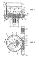
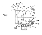
- the device has a receptacle or cutting compressor 1 for the processed, in particular thermoplastic, plastic material which is introduced into this container 1 from above by means of a conveyor, not shown, for example, a conveyor belt.
- the supplied plastic material may be pre-shredded and / or pre-dried.
- the receptacle 1 is cylindrical pot-shaped with vertical side walls 2 and has a horizontal flat bottom 3 with circular cross-section.
- the receptacle 1 may be closed at the top or open.
- a shaft 4 penetrates, sealed, the bottom 3 and has a vertical axis 8, which coincides with the container axis.
- the shaft 4 is driven by a motor 3 arranged below the bottom 3 with gear 6 for rotational movement.
- a rotor 7 and a carrier disc arranged above 9 are rotationally connected.
- the rotor 7 is formed by a circular cylindrical block whose axial extent h is substantially greater than that of the flat carrier disk 9, whose radial extent d, however, is substantially smaller than that of the carrier disk 9.
- a free space 10th formed, which communicates with the located above the support plate 9 space 26 of the container 1 via an annular gap 11 in free flow communication for the machined material, which is between the periphery of the support plate 9 and the side wall 2 of the container 1.
- an annular gap 11 in free flow communication for the machined material, which is between the periphery of the support plate 9 and the side wall 2 of the container 1.
- the upper support plate 9 carries on its upper side firmly arranged upper mixing tools 21, which mix the material located in the space 26 of the container 1 and / or crush and / or heat.
- the tools 21 may be formed with cutting edges 22 which are curved or angled against the direction of rotation of the carrier disk 9 (arrow 23) ( Fig. 2 ) may be formed to achieve a pulling cut.
- a screw housing 16 connects, in which a worm 17 is rotatably mounted, which is driven at its one end face by a motor 18 with gear 19 for rotational movement and the supplied plastic material at the other end, for example through an extruder head 20, expresses. It can be a single screw, a twin screw or a multiple screw.
- the screw housing 16 is connected approximately tangentially to the container, so that deflections of the plastic material plasticized by the screw 16 in the region of its exit from the housing 16 are avoided.
- the auger 17 may also be a pure auger which feeds the material prepared in the container 1 for further use, e.g. an extruder.
- the introduced into the container 1 material is usually not completely dry and / or it has impurities that emit during processing in the container volatile substances, such as water vapor, cleavage products from the machined material, evaporated coolant, volatile substances Coloring material and / or printing material, etc.
- the carrier disk 9 according to Fig. 1 and 2 at least one, but preferably a plurality of apertures 36, which connect the space 26 above the carrier disk 9 with the space 10 located below it. Through these breakthroughs 36, the trapped in the space 10 volatile substances can escape through the support disk 9 through up and so are discharged from the container 10, for example, by a suction 51.
- openings may be formed by circular or slotted holes in a cross section.
- At least some of these apertures 36 are arranged near the axis 8 of the container 1, directly behind the tools 21, so that the apertures 36, seen in the direction of rotation (arrow 23) of the support disk 9, the trailing edges 37 and edges of the tools 21st lie adjacent.
- the induced by the tools 21 in their circulation at their trailing edge suction supports the extraction of the volatile substances through the apertures 36 upwards.
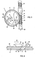
- the axes of the apertures 36 may be vertical, but it is more appropriate, these axes 38 according to Fig. 6 to be arranged obliquely, in such a way that they are inclined both to the plane of the top surface 39 of the carrier disc 9 and to the container axis 8.
- the inclination of the walls 40 of the apertures is suitably between 30 and 60 °, preferably at about 45 °. This inclination is chosen so that the entry end 41 of each breakthrough 36, seen in the direction of rotation of the support disk 9 (arrow 23) is further forward than the exit end 42. This measure also supports the aforementioned suction and acts a direct Falling of the goods from the space 26 through the openings 36 in the space 10 against.
- Fig. 3 it is expedient to provide the apertures or at least some of them with a cover 28 which covers the opening 36 all around, except for an outwardly directed towards the circumference 43 of the support disk 9 and radially (with respect to the axis 8) directed Opening 35.
- the size, i. the cross-sectional area of the apertures 36 depends on the amount of volatiles to be removed. As a rule, it is sufficient to dimension the cross-sectional area of all apertures 36 to be maximally as large as the cross-sectional area of all screws or screw housings of the extruder or screws 17 which are in fluid communication with the discharge opening 15 of the container 1.
- a gas supply means 50 In the lower region of the side wall 2 of the receptacle 1 is a gas supply means 50, arranged or opens in the side wall 2 of the receptacle 1 in the receptacle 1 a.
- This gas supply means 50 is formed as an active gas supply means 50 in the form of a nozzle, i. it can be injected with pressure gas inside the cutter compactor.
- the nozzle is arranged at such a height or at a distance from the bottom surface 3 that they are constantly below the procedurally predetermined filling level of the cutting material 1 or rotating material particles or the level of formed during the movement or rotation of the material particles Mischthrombe lies.
- the nozzle is in the range of the lower third of the total height of the cutting compressor. 1
- the nozzle 50a is arranged in the side wall 2 in the region between the upper mixing tools 21 or the upper carrier disk 9 and the lower mixing tools 12 or the lower carrier disk 29 and thus opens into the lower interior part 10.
- the gas supply means advantageously open in the region between the uppermost and the lower carrier disk or in the region between the uppermost and the lowermost mixing tools. In this way, an advantageous flow and mixing and thus an advantageous work-up of the material can be ensured.
- the gas supply means 50 not in the region of the edges of the carrier disks or the mixing tools, but in particular in each case, enter or are arranged in the region between in each case two carrier disks or mixing tools in the receptacle 1.
- the nozzle is formed as a singular opening in the side wall 2 and has a diameter of about 70 mm. In addition, further such openings may be formed at the same height, in particular evenly distributed over the circumference.
- the nozzle is provided with a cover or shield 60 which prevents the rotating material from being pushed into the interior of the nozzle.
- the cover is advantageously located upstream of the direction of rotation of the material in front of the nozzle.
- the nozzle is arranged substantially on the discharge opening 15 opposite side of the receptacle 1.
- a gas discharge means 51 in the form of an active gas suction or a suction pump 53 is provided in the region above the material level.
- the gas discharge means 51 may also be formed as a passive gas discharge means, which is the case in a simple embodiment, in particular in an open-topped receptacle 1.
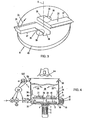
- the alternative embodiment according to the Fig. 4 and 5 differs from that after the Fig. 1 and 2 above all, that the lower mixing tools 12 are not suspended oscillating, but sit rigidly on another support disk 29 which is arranged coaxially to the support disk 9 and can be driven via the same shaft 4 for rotational movement.
- the rotor 7 can be formed narrower or omitted as an extension of the shaft 4 in its entirety.
- the lower mixing tools 12 are arranged at the level of the discharge opening 15 of the container 1 in order to be able to effectively convey the processed plastic material located in the space 10 into the intake opening 27 of the screw housing 16.
- the further lower mixing tools 12 located in the space 10 below the upper carrier disk 9 are fixedly arranged on a further lower carrier disk 29 arranged below the carrier disk 9, but may also be suspended pivotably on the carrier disk 9 or on the shaft 4.
- a gas supply means 50 is arranged in the region between the carrier disks 9,29 or between the upper and lower mixing tools 21,12 and opens into the space 10 a.
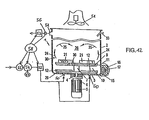
- Fig. 4 shows, in the upper cutting chamber 26 above the support plate 9, a temperature measuring unit 30 and a cooling device 33 is provided, the latter may be formed as a coolant injection.
- a suction 51 may be provided above the resulting in this cutting space 26 Mischtrombe.
- a measuring device 56 is arranged, with which the temperature of the exiting gas and / or its moisture and / or the content of the impurities in this gas can be determined.
- a control device 58 is shown schematically, with which the device according to the invention or its individual elements can be controlled or adjusted.
- the control device 58 is connected to the gas discharge means 51 and the gas supply means 50, shown.
- the control device 58 In the path of the supplied gas are a heater 54 and a gas drying device 55 and a pump or blower 52. These units can be controlled under the action of the controller 58, the amount or the temperature or the pressure of the supplied gas. It is also possible to use the temperature or humidity of the exiting gas for controlling the temperature and / or amount and / or the pressure of the supplied gas.
- the amount of gas supplied through the introduction opening 50 substantially corresponds to the amount of gas leaving through the gas outlet 51.
- the escaping gas may be entrainment units for the entrained impurities, e.g. Cyclones or gas separators have and can be supplied as purified gas, if necessary recycled, in turn, the gas inlet opening 50.
- FIGS. 7 and 8 The device according to FIGS. 7 and 8 is similar to the one in Fig. 1 and 2 illustrated embodiment, however, no breakthroughs 36 are formed in the upper carrier disk 9. With regard to the embodiment, reference is made to the above statements.
- a lower free interior part 10 is formed below the upper support plate 9, which is located above the carrier disc 9 upper interior part 26 of the container 1 via the between the outer periphery of the support plate 9 and the side wall 2 of the container 1 existing annular gap eleventh is in free flow connection for the machined material.
- lower mixing tools 12 are arranged, which rotate in this annular space about the axis 8.
- the plastic material is forced into a discharge opening 15 of the container 1, which opening 15 is at the height of the tools 12 and connects the lower interior part 10 of the container 1 with the interior of a cylindrical housing 16, in which a screw 17 is rotatably mounted.
- the upper carrier plate 9 also carries upper mixing tools 21, which are firmly connected to the carrier plate 9. These upper mixing tools 21 mix and / or comminute and / or heat the material located in the upper interior part 26 of the container 1. For effective comminution, it is expedient to form the tools 21 with cutting edges 22.
- the screw 17 must therefore bring less work into the plastic mass to bring the plastic mass to the desired degree of plasticization, which has the consequence that high thermal peak stresses on the plastic material in the screw housing 16 accounts. As a result, the plastic material is spared and substantially saved on energy for driving the worm 17.
- the shape and size of the annular space 10 depend on the field of application envisaged.
- the distance h, in which the underside of the support disk 9 from the bottom 3 of the container 1, depends on the height of the rotor 7 and also on the size and location of the discharge opening 15.
- the height h of the annular space 10th at least equal, preferably substantially larger than the diameter d of the screw 17 and the inner diameter of the screw housing 16.
- Other cross-sectional shapes of this annular space are possible, in particular when other tools circulate in this annular space 10, for example a rotor 7 designed as a paddle wheel.
- the size of the annular gap 11 is of influence for the described mode of operation.
- This annular gap should not be too large, so that it is prevented that larger material particles can pass through this annular gap 11.
- this gap should not be too small, otherwise too little material passes under the support plate 9 in the lower interior part 10 and thus there is a risk that the screw 17 is insufficiently filled.
- the size of the annular gap 11 may be formed variable, for example by means of the support plate 9 supported, relative to their adjustable components through which the gap 11 are partially covered or released in an enlarged width can. Such components may optionally also be provided on the wall 2 of the container 1.
- a gas supply means 50 is disposed in the region between the support disks 9,29 or between the upper and lower mixing tools 21,12 and opens into the space 10 a.
- Fig. 9 shows a further embodiment in vertical section.
- This device has a receptacle 1, in which only a single carrier disc 9,29 is provided with mixing tools 12,21 in the lower region just above the bottom 3 at the level of the discharge opening 15. These mixing tools 12,21 produce a movement of the material ponds or a Mischthrombe 25th
- an additional active gas supply means 50 in the form of an annular gap surrounding the shaft 4, in particular almost continuously, through which gas is blown in with a fan 52.
- a further active gas supply means 50 is formed, which also extends circumferentially over almost the entire circumference Annular gap is formed.
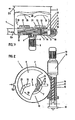
- 10 and 11 show a further embodiment in vertical section and in plan view.
- the 10 and 11 only partially shown device - so only the bottom support plate 29 and the lowest mixing tools are shown - corresponds in the Academic, not shown in the Fig. 1 to 9 shown devices. It is thus in terms of the features not shown on this Fig. 1 to 9 directed.
- conveying wings 65 On the underside of the lowermost carrier disk 29 a plurality of conveying wings 65 are arranged. These conveying wings 65 extend radially from the region of the center of the carrier disk 29 and curved in the opposite direction to the direction of rotation and extend almost over the entire radius of the carrier disk 29.
- the conveying wings 65 are designed as bar-shaped webs and protrude into the region between the carrier disk 29 and the bottom surface 3 inside.
- the conveying wings 65 generate a flow during operation and cause a material flow which causes no material to be treated to remain in this area below the carrier disk 29.
- additional gas supply means 50 are formed near the central axis, which open into the region below the support plate 29.
- the gas supply means 50 may be formed as active or passive gas supply means 50a, 50b. In this way, gas or air can be actively introduced into the area below the support disk 29 or is sucked in by the conveying wings 65. The gas then flows as in Fig. 10 represented by the arrows 68, through the annular gap 11 upwards and thereby supports the application of the material to be treated from the area below the support plate 29. Also, the gas flows through any formed apertures 36, as in Fig. 10 represented by the arrows 69 and transported in this way material upwards.
- the conveying wings 65 thus interact with the gas supply means 50 and possibly the openings in an advantageous manner and thus ensure an effective discharge of material from the region below the carrier disk 29.
- Such conveying wings 65 or such a combination arrangement of conveying wings 65, openings 36 and / or gas supply means 50 can be found in all in Fig. 1 to 9 be formed devices shown.
- Fig. 12 is shown a further advantageous embodiment. This is analogous to the embodiment according to Fig. 4 and 5 built up. It is in this regard to the comments Fig. 4 and 5 directed.
- the gas supply means 50 In contrast to Fig. 4 and 5 are the gas supply means 50, but additionally formed in the bottom surface 3, as in the embodiments of the Fig. 9 . 10 or 11 is the case.
Landscapes
- Engineering & Computer Science (AREA)
- Food Science & Technology (AREA)
- Mechanical Engineering (AREA)
- Chemical & Material Sciences (AREA)
- Chemical Kinetics & Catalysis (AREA)
- Environmental & Geological Engineering (AREA)
- Processing And Handling Of Plastics And Other Materials For Molding In General (AREA)
- Crushing And Pulverization Processes (AREA)
- Separation, Recovery Or Treatment Of Waste Materials Containing Plastics (AREA)
- Drying Of Solid Materials (AREA)
Priority Applications (8)
| Application Number | Priority Date | Filing Date | Title |
|---|---|---|---|
| PL10005120T PL2221158T3 (pl) | 2007-02-15 | 2008-02-08 | Sposób i urządzenie do przygotowywania materiału |
| DK10005119T DK2218565T3 (da) | 2007-02-15 | 2008-02-08 | Fremgangsmåde og apparat til bearbejdning af et materiale |
| EP20100005120 EP2221158B1 (de) | 2007-02-15 | 2008-02-08 | Verfahren und Vorrichtung zur Aufbereitung eines Materials |
| EP20100005119 EP2218565B1 (de) | 2007-02-15 | 2008-02-08 | Verfahren und Vorrichtung zur Aufbereitung eines Materials |
| DK10005120T DK2221158T3 (da) | 2007-02-15 | 2008-02-08 | Fremgangsmåde og apparat til behandling af et materiale |
| PL10005119T PL2218565T3 (pl) | 2007-02-15 | 2008-02-08 | Sposób i urządzenie do przygotowywania materiału |
| PL08706015T PL2117796T3 (pl) | 2007-02-15 | 2008-02-08 | Sposób i urządzenie do uzdatniania materiału |
| SI200830696T SI2117796T1 (sl) | 2007-02-15 | 2008-02-08 | Postopek in naprava za pripravo materiala |
Applications Claiming Priority (2)
| Application Number | Priority Date | Filing Date | Title |
|---|---|---|---|
| ATA244/2007A AT504854B1 (de) | 2007-02-15 | 2007-02-15 | Verfahren und vorrichtung zur aufbereitung eines materials |
| PCT/AT2008/000045 WO2008098274A1 (de) | 2007-02-15 | 2008-02-08 | Verfahren und vorrichtung zur aufbereitung eines materials |
Related Child Applications (2)
| Application Number | Title | Priority Date | Filing Date |
|---|---|---|---|
| EP10005120.0 Division-Into | 2010-05-17 | ||
| EP10005119.2 Division-Into | 2010-05-17 |
Publications (2)
| Publication Number | Publication Date |
|---|---|
| EP2117796A1 EP2117796A1 (de) | 2009-11-18 |
| EP2117796B1 true EP2117796B1 (de) | 2012-06-20 |
Family
ID=37986761
Family Applications (3)
| Application Number | Title | Priority Date | Filing Date |
|---|---|---|---|
| EP20080706015 Active EP2117796B1 (de) | 2007-02-15 | 2008-02-08 | Verfahren und vorrichtung zur aufbereitung eines materials |
| EP20100005120 Active EP2221158B1 (de) | 2007-02-15 | 2008-02-08 | Verfahren und Vorrichtung zur Aufbereitung eines Materials |
| EP20100005119 Active EP2218565B1 (de) | 2007-02-15 | 2008-02-08 | Verfahren und Vorrichtung zur Aufbereitung eines Materials |
Family Applications After (2)
| Application Number | Title | Priority Date | Filing Date |
|---|---|---|---|
| EP20100005120 Active EP2221158B1 (de) | 2007-02-15 | 2008-02-08 | Verfahren und Vorrichtung zur Aufbereitung eines Materials |
| EP20100005119 Active EP2218565B1 (de) | 2007-02-15 | 2008-02-08 | Verfahren und Vorrichtung zur Aufbereitung eines Materials |
Country Status (20)
Families Citing this family (73)
| Publication number | Priority date | Publication date | Assignee | Title |
|---|---|---|---|---|
| AT504709B1 (de) * | 2006-11-23 | 2008-09-15 | Erema | Verfahren und vorrichtung zur einbringung von zusatzstoffen |
| AT507856B1 (de) * | 2009-02-03 | 2011-09-15 | Starlinger & Co Gmbh | Vorrichtung zur zerkleinerung von kunststoff |
| AT508925B1 (de) * | 2010-01-14 | 2011-05-15 | Erema | Läuferscheibe |
| AT508895B1 (de) * | 2010-01-14 | 2011-05-15 | Erema | Läuferscheibe |
| AT508924B1 (de) | 2010-01-14 | 2011-05-15 | Erema | Läuferscheibe |
| BR112012018288B1 (pt) | 2010-01-22 | 2020-01-21 | Erema Engineering Recycling Maschinen Und Anlagen Gesellschaft M.B.H. | processo de processamento e desintoxicação de um material e dispositivo para a realização do processo |
| AT511362B1 (de) | 2010-04-14 | 2014-01-15 | Erema | Vorrichtung zum aufbereiten von kunststoffmaterial |
| AT509323B1 (de) | 2010-04-16 | 2011-08-15 | Erema | Verfahren und vorrichtung zur aufbereitung und reinigung eines polymermaterials |
| AT512208B1 (de) * | 2011-10-14 | 2015-02-15 | Erema | Vorrichtung zum aufbereiten von kunststoffmaterial |
| AT512146B1 (de) * | 2011-10-14 | 2015-02-15 | Erema | Vorrichtung zum aufbereiten von kunststoffmaterial |
| AT512207B1 (de) * | 2011-10-14 | 2015-02-15 | Erema | Vorrichtung zum aufbereiten von kunststoffmaterial |
| AT512147B1 (de) | 2011-10-14 | 2015-02-15 | Erema | Vorrichtung zum aufbereiten von kunststoffmaterial |
| AT512212B1 (de) * | 2011-10-14 | 2015-02-15 | Erema | Vorrichtung zum aufbereiten von kunststoffmaterial |
| AT512149B1 (de) * | 2011-10-14 | 2015-02-15 | Erema | Vorrichtung zum aufbereiten von kunststoffmaterial |
| AT512205B1 (de) * | 2011-10-14 | 2015-02-15 | Erema | Vorrichtung zum aufbereiten von kunststoffmaterial |
| AT512223B1 (de) * | 2011-10-14 | 2015-02-15 | Erema | Vorrichtung zum aufbereiten von kunststoffmaterial |
| AT512209B1 (de) * | 2011-10-14 | 2015-02-15 | Erema | Vorrichtung zum aufbereiten von kunststoffmaterial |
| AT512145B1 (de) * | 2011-10-14 | 2015-02-15 | Erema | Vorrichtung zum aufbereiten von kunststoffmaterial |
| AT512222B1 (de) | 2011-10-14 | 2015-02-15 | Erema | Vorrichtung zum aufbereiten von kunststoffmaterial |
| AT512148B1 (de) | 2011-10-14 | 2015-02-15 | Erema | Vorrichtung zum aufbereiten von kunststoffmaterial |
| US8956892B2 (en) * | 2012-01-10 | 2015-02-17 | Asm Technology Singapore Pte. Ltd. | Method and apparatus for fabricating a light-emitting diode package |
| US9011557B2 (en) * | 2012-04-03 | 2015-04-21 | General Electric Company | System for drying a gasification feed |
| DE102012104375A1 (de) | 2012-05-22 | 2013-11-28 | Rehau Ag + Co | Verfahren und Vorrichtung zur Herstellung eines WPC-Compounds |
| JP6656155B2 (ja) * | 2013-12-31 | 2020-03-04 | メディ−フィジックス・インコーポレイテッド | 原料を混合するための装置 |
| CN103736564A (zh) * | 2014-01-02 | 2014-04-23 | 浙江海洋学院 | 一种船用非金属密封废料粉碎设备 |
| AT515363B1 (de) * | 2014-01-28 | 2018-12-15 | Erema Eng Recycling Maschinen & Anlagen Gmbh | Zerkleinerungswerkzeug |
| AT517756B1 (de) * | 2015-09-22 | 2017-11-15 | Next Generation Recyclingmaschinen Gmbh | Vorrichtung und Verfahren zur Verarbeitung von thermoplastischem Kunststoff mit einer Blasvorrichtung für eine Transportschnecke |
| WO2018048736A1 (en) * | 2016-09-06 | 2018-03-15 | Geo-Tech Polymers, Llc | Film treatment system |
| CN109049400B (zh) * | 2016-09-30 | 2021-06-29 | 漳州龙文区信创友工业设计有限公司 | 一种注塑工艺用pa12干燥装置的干燥方法 |
| KR101820118B1 (ko) * | 2017-07-14 | 2018-01-18 | (주)그린파이프 | 파이프 제조장치 |
| CN107442227A (zh) * | 2017-07-24 | 2017-12-08 | 江苏天蓬饲料有限公司 | 一种带除湿功能的饲料生产用粉碎机 |
| PL3473396T3 (pl) * | 2017-10-17 | 2021-12-13 | Buss Ag | Asymetryczny dwuskrzydłowy wałek ślimakowy do maszyny mieszającej oraz ugniatającej |
| CN107774390A (zh) * | 2017-11-16 | 2018-03-09 | 广州安适易环境科技有限公司 | 立式垃圾破碎机的破碎组件 |
| CN108097399B (zh) * | 2017-12-05 | 2020-02-25 | 广西贵港东方传奇食品科技股份有限公司 | 一种立式酿酒原料制粉装置 |
| WO2020109675A1 (fr) * | 2018-11-30 | 2020-06-04 | Family Self Care | Carrousel de distribution |
| CN108906227B (zh) * | 2018-07-05 | 2023-09-19 | 福建南方路面机械股份有限公司 | 一种立轴式破碎机及其破碎方法 |
| CN108914665A (zh) * | 2018-08-23 | 2018-11-30 | 江苏大唐机械有限公司 | 一种水力碎浆机转子装置 |
| TWI828878B (zh) * | 2019-03-29 | 2024-01-11 | 日商夏普股份有限公司 | 粉碎裝置 |
| DE102019205147A1 (de) | 2019-04-10 | 2020-10-15 | Glatt Gesellschaft Mit Beschränkter Haftung | Verfahren zur Entleerung einer Vorrichtung zur Herstellung von Granulaten oder Extrudaten |
| DE102019205148A1 (de) | 2019-04-10 | 2020-10-15 | Glatt Gesellschaft Mit Beschränkter Haftung | Vorrichtung zur Herstellung von Granulaten oder Extrudaten |
| CN110181717B (zh) * | 2019-07-10 | 2024-06-04 | 吉林重通成飞新材料股份公司 | 风电叶片材料筛分设备及风电叶片材料筛分方法 |
| CN110328775B (zh) * | 2019-07-18 | 2024-04-05 | 南京汇科高分子材料有限公司 | 一种用于生产玻璃包边用聚氨酯组合料的干燥箱 |
| CN110480869B (zh) * | 2019-07-28 | 2021-09-17 | 盐城市贝迪塑业有限公司 | 一种再生塑料颗粒干燥装置及进料结构 |
| AT523143B1 (de) * | 2019-10-11 | 2021-11-15 | Erema Eng Recycling Maschinen & Anlagen Gmbh | Anordnung zum Granulieren von extrudiertem Material |
| AT523082B1 (de) * | 2019-10-16 | 2022-07-15 | Pureloop Gesmbh | Vorrichtung zur Verarbeitung von Material, insbesondere von Kunststoffmaterial |
| CN111421692B (zh) * | 2020-03-29 | 2022-02-01 | 太仓民翔特种无纺布有限公司 | 应用于无纺布加工原料投放设备中的闸门系统的闸门驱动控制机构 |
| CN111497064A (zh) * | 2020-03-30 | 2020-08-07 | 唐汉平 | 城市生活塑料垃圾的压缩处理设备及处理方法 |
| CN111774155B (zh) * | 2020-07-10 | 2022-06-03 | 深圳市圣西马生物技术有限公司 | 一种生物质粉碎发酵系统 |
| CN111957423A (zh) * | 2020-07-30 | 2020-11-20 | 徐陈花 | 一种高效型农副产品粉碎设备 |
| CN111993616A (zh) * | 2020-08-10 | 2020-11-27 | 广西长科新材料有限公司 | 一种高效br和sbr橡胶的溶解设备 |
| CN112248267B (zh) * | 2020-09-28 | 2022-05-20 | 夜视丽新材料(仙居)有限公司 | 一种反光膜uv生产设备 |
| CN112466683B (zh) * | 2020-11-19 | 2022-01-07 | 山东泰开电力电子有限公司 | 一种利用气旋分离原理的电容器真空干燥浸渍装置 |
| CN112495534B (zh) * | 2020-11-25 | 2022-04-08 | 上海信谊天平药业有限公司 | 一种制药用原材粉碎装置 |
| CN112892761A (zh) * | 2020-12-28 | 2021-06-04 | 新昌县辰逸服饰有限公司 | 一种防风涤纶织物涂层剂加工装置 |
| CN112720824B (zh) * | 2020-12-29 | 2022-03-01 | 桂林航天工业学院 | 一种陶瓷生产装置的材料回收环保装置 |
| CN112892768A (zh) * | 2021-01-19 | 2021-06-04 | 李文音 | 一种用于高速混合制粒机的控制装置 |
| CN112827629A (zh) * | 2021-01-22 | 2021-05-25 | 赵绪光 | 一种医用检验用匀浆装置以及使用方法 |
| CN113198366B (zh) * | 2021-04-27 | 2022-05-24 | 张彦伟 | 一种畜牧用饲料加工装置 |
| CN113340094B (zh) * | 2021-06-28 | 2022-07-22 | 江西省农业科学院农业工程研究所 | 一种批次粮食烘干作业量远程监测方法 |
| CN113477379B (zh) * | 2021-07-29 | 2022-09-30 | 九江一晖环保集团有限公司 | 一种基于物料衡算的废弃物金属回收方法 |
| CN113877681B (zh) * | 2021-09-09 | 2022-11-01 | 内蒙古自治区农牧业科学院 | 一种过瘤胃5-羟色胺包被装置及包被方法 |
| CN113952997B (zh) * | 2021-09-15 | 2022-11-22 | 智泽工程技术有限公司 | 一种建筑用混凝土废料粉碎回收装置 |
| CN114160276B (zh) * | 2021-11-08 | 2023-01-10 | 江苏大学镇江流体工程装备技术研究院 | 一种应用于渣浆泵的多重固液分离破碎装置 |
| CN114653440A (zh) * | 2022-03-17 | 2022-06-24 | 重庆东星炭素材料有限公司 | 一种生产锂电池石墨负极材料的高效率磨粉机 |
| JP2023175107A (ja) * | 2022-05-30 | 2023-12-12 | ウツミリサイクルシステムズ株式会社 | 耐熱性ポリエチレンテレフタレートトレイおよびその製造方法 |
| CN115487928B (zh) * | 2022-08-17 | 2023-09-19 | 山东戴瑞克新材料有限公司 | 一种带氮气保护的粉碎过滤装置 |
| DE102022122710A1 (de) | 2022-09-07 | 2024-03-07 | Karl Schnell Gmbh & Co. Kg | Zerkleinerungsmaschine und Verfahren zum Zerkleinern eines Produkts unter Zuführung eines Fluids |
| DE102022122711B3 (de) * | 2022-09-07 | 2024-03-07 | Karl Schnell Gmbh & Co. Kg | Zerkleinerungsmaschine mit einem mehrteiligen Gehäuse |
| CN115816699B (zh) * | 2022-11-16 | 2025-09-30 | 勐腊金色橡胶有限公司 | 一种基于橡胶加工用破碎筛选设备 |
| CN116272497B (zh) * | 2023-03-30 | 2025-08-29 | 厦门金世宇科技有限公司 | 一种菌菇培育基质混匀装置 |
| CN116692377A (zh) * | 2023-08-08 | 2023-09-05 | 江苏天利智能科技有限公司 | 一种投料站用输送装置 |
| CN117160591B (zh) * | 2023-08-15 | 2024-04-30 | 民安医药(山东)有限公司 | 一种益生菌粉及其生产装置 |
| AT528144A1 (de) * | 2024-03-19 | 2025-10-15 | Erema Eng Recycling Maschinen & Anlagen Gmbh | Extruder zur Bearbeitung von Polymermaterialien |
Family Cites Families (15)
| Publication number | Priority date | Publication date | Assignee | Title |
|---|---|---|---|---|
| DE2432494A1 (de) | 1974-07-04 | 1976-01-22 | Erich Beck | Vorrichtung zum ueberfuehren von kunststoffabfaellen in ein granulat |
| DE2609850A1 (de) * | 1976-03-10 | 1977-09-15 | Weiss Gmbh & Co Kg Maschinen F | Verfahren und vorrichtung zur aufbereitung von duennwandigen kunststoffabfaellen zu kunststoffgranulat |
| GB2077125B (en) * | 1980-05-16 | 1984-10-24 | Draiswerke Gmbh | Apparatus for feeding flowable solids and liquids to treatment machines |
| ES525783A0 (es) * | 1982-09-24 | 1985-03-01 | Freunt Ind Co Ltd | Maquina para granular y revestir |
| HU196717B (en) * | 1986-02-20 | 1989-01-30 | Mta Mueszaki Kemiai Kutato Int | Apparatus and method for fluidization contacting materials |
| JPH04163004A (ja) * | 1990-10-24 | 1992-06-08 | Matsuji Nakagome | プラスチック乾燥装置 |
| DE4200827C2 (de) * | 1992-01-15 | 1997-09-04 | Jackering Altenburger Masch | Verfahren und Vorrichtung zur Erfassung von Kunststoff oder Gummi aus einem Abfallgemisch |
| DE9202161U1 (de) * | 1992-02-20 | 1992-04-09 | Schmoll, Heinz, 6242 Kronberg | Gerät zum Zerkleinern von leeren Ölkanistern aus Kunststoff |
| DE4205073A1 (de) | 1992-02-20 | 1993-08-26 | Heinz Schmoll | Geraet zum zerkleinern von leeren oelkanistern aus kunststoff |
| AT405726B (de) | 1995-04-11 | 1999-11-25 | Bacher Helmut | Vorrichtung zum aufbereiten thermoplastischen kunststoffgutes |
| RU2133196C1 (ru) * | 1998-03-11 | 1999-07-20 | Уминский Анатолий Аркадьевич | Способ утилизации отходов фторопластов и получения преимущественно тонкодисперсного порошка и устройство для его осуществления |
| RU2153416C1 (ru) * | 1999-01-12 | 2000-07-27 | Колесников Игорь Владимирович | Установка для криогенного измельчения пластмасс |
| AT407970B (de) | 1999-06-02 | 2001-07-25 | Bacher Helmut | Vorrichtung und verfahren zum aufbereiten von, insbesondere thermoplastischem, kunststoffmaterial |
| WO2000074834A1 (en) * | 1999-06-07 | 2000-12-14 | Freund Industrial Co., Ltd. | Centrifugally rolling granulating device and method of treating powder and granular material using the device |
| AT413199B (de) * | 2004-03-17 | 2005-12-15 | Erema | Vorrichtung zum aufbereiten von kunststoffmaterial |
-
2007
- 2007-02-15 AT ATA244/2007A patent/AT504854B1/de active
-
2008
- 2008-02-08 WO PCT/AT2008/000045 patent/WO2008098274A1/de not_active Ceased
- 2008-02-08 KR KR1020107020330A patent/KR101618348B1/ko not_active Expired - Fee Related
- 2008-02-08 EP EP20080706015 patent/EP2117796B1/de active Active
- 2008-02-08 CN CN201510647471.6A patent/CN105269709A/zh active Pending
- 2008-02-08 PT PT08706015T patent/PT2117796E/pt unknown
- 2008-02-08 RU RU2009134337/05A patent/RU2461459C2/ru active
- 2008-02-08 EP EP20100005120 patent/EP2221158B1/de active Active
- 2008-02-08 KR KR1020167004546A patent/KR20160028485A/ko not_active Withdrawn
- 2008-02-08 UA UAA200909073A patent/UA90641C2/uk unknown
- 2008-02-08 BR BR122013024728A patent/BR122013024728B1/pt not_active IP Right Cessation
- 2008-02-08 DE DE200820018151 patent/DE202008018151U1/de not_active Expired - Lifetime
- 2008-02-08 DK DK10005120T patent/DK2221158T3/da active
- 2008-02-08 EP EP20100005119 patent/EP2218565B1/de active Active
- 2008-02-08 US US12/526,755 patent/US8616478B2/en active Active
- 2008-02-08 ES ES10005119T patent/ES2389166T3/es active Active
- 2008-02-08 AU AU2008215149A patent/AU2008215149B2/en active Active
- 2008-02-08 PT PT10005119T patent/PT2218565E/pt unknown
- 2008-02-08 ES ES10005120T patent/ES2389874T3/es active Active
- 2008-02-08 KR KR1020097019245A patent/KR101568655B1/ko active Active
- 2008-02-08 BR BRPI0807740-1A2A patent/BRPI0807740A2/pt active IP Right Grant
- 2008-02-08 KR KR1020157036335A patent/KR20160005786A/ko not_active Withdrawn
- 2008-02-08 CN CNA2008800050342A patent/CN101610886A/zh active Pending
- 2008-02-08 JP JP2009549744A patent/JP2010517831A/ja active Pending
- 2008-02-08 MX MX2009008406A patent/MX2009008406A/es active IP Right Grant
- 2008-02-08 DK DK10005119T patent/DK2218565T3/da active
- 2008-02-08 CA CA2678246A patent/CA2678246C/en active Active
- 2008-02-08 PL PL10005120T patent/PL2221158T3/pl unknown
- 2008-02-08 SI SI200830696T patent/SI2117796T1/sl unknown
- 2008-02-08 DK DK08706015T patent/DK2117796T3/da active
- 2008-02-08 SI SI200830731T patent/SI2221158T1/sl unknown
- 2008-02-08 PL PL08706015T patent/PL2117796T3/pl unknown
- 2008-02-08 RU RU2010130271/05A patent/RU2492045C2/ru active
- 2008-02-08 SI SI200830697T patent/SI2218565T1/sl unknown
- 2008-02-08 CN CN2010102030075A patent/CN101869866B/zh active Active
- 2008-02-08 ES ES08706015T patent/ES2389895T3/es active Active
- 2008-02-08 PT PT10005120T patent/PT2221158E/pt unknown
- 2008-02-08 PL PL10005119T patent/PL2218565T3/pl unknown
-
2009
- 2009-07-21 ZA ZA200905078A patent/ZA200905078B/xx unknown
-
2010
- 2010-07-09 JP JP2010157278A patent/JP2011005862A/ja active Pending
- 2010-08-06 AU AU2010209997A patent/AU2010209997B2/en not_active Ceased
Also Published As
Similar Documents
| Publication | Publication Date | Title |
|---|---|---|
| EP2117796B1 (de) | Verfahren und vorrichtung zur aufbereitung eines materials | |
| EP2558262B1 (de) | Verfahren und vorrichtung zur aufbereitung und reinigung von polymermaterial mittels einer lanze | |
| EP1729944B1 (de) | Vorrichtung zum aufbereiten von kunststoffmaterial | |
| EP2286973B1 (de) | Verfahren und Vorrichtung zur Behandlung von Kunststoffmaterial | |
| EP0835882B1 (de) | Verfahren und Vorrichtung zum gleichzeitigen Mahlen und Trocknen eines feuchten Celluloseether enthaltenden Mahlgutes | |
| EP2766163B1 (de) | Vorrichtung zum aufbereiten von kunststoffmaterial | |
| EP1276597B1 (de) | Vorrichtung und verfahren zum aufbereiten von thermoplastischem kunststoffgut | |
| DE4103932A1 (de) | Einrichtung zur verringerung des volumens von kunststoffschaumabfaellen | |
| EP1364713B9 (de) | Messermühle zur Zerkleinerung von Kunststoffmaterial und Verfahren zum Betrieb | |
| WO2007090599A1 (de) | Vorrichtung und verfahren zur einspeisung von feuchten und/oder klebrigen produkten, insbesondere zellulose, in eine luftwirbelmühle | |
| EP2393598B1 (de) | Vorrichtung zur zerkleinerung von kunststoff | |
| DE102004035260A1 (de) | Vorrichtung und Verfahren zum Herstellen von Presslingen, Pellets, Compounds, Composites, Agglomeraten, Granulaten und dergleichen | |
| DE102019205147A1 (de) | Verfahren zur Entleerung einer Vorrichtung zur Herstellung von Granulaten oder Extrudaten | |
| EP4584024A1 (de) | Zerkleinerungsmaschine und verfahren zum zerkleinern eines produkts unter zuführung eines fluids | |
| DE10011949C2 (de) | Anlage zur Verarbeitung von umweltbelastenden Abprodukten | |
| DE20011744U1 (de) | Einwellenzerkleinerer | |
| AT503325B1 (de) | Materialaufbereitungsvorrichtung |
Legal Events
| Date | Code | Title | Description |
|---|---|---|---|
| PUAI | Public reference made under article 153(3) epc to a published international application that has entered the european phase |
Free format text: ORIGINAL CODE: 0009012 |
|
| 17P | Request for examination filed |
Effective date: 20090807 |
|
| AK | Designated contracting states |
Kind code of ref document: A1 Designated state(s): AT BE BG CH CY CZ DE DK EE ES FI FR GB GR HR HU IE IS IT LI LT LU LV MC MT NL NO PL PT RO SE SI SK TR |
|
| DAX | Request for extension of the european patent (deleted) | ||
| 17Q | First examination report despatched |
Effective date: 20100712 |
|
| REG | Reference to a national code |
Ref country code: DE Ref legal event code: R079 Ref document number: 502008007474 Country of ref document: DE Free format text: PREVIOUS MAIN CLASS: B29B0017000000 Ipc: B02C0018080000 |
|
| GRAP | Despatch of communication of intention to grant a patent |
Free format text: ORIGINAL CODE: EPIDOSNIGR1 |
|
| RIC1 | Information provided on ipc code assigned before grant |
Ipc: B29B 13/10 20060101ALI20111206BHEP Ipc: B29B 17/04 20060101ALI20111206BHEP Ipc: B01F 15/02 20060101ALI20111206BHEP Ipc: B29B 17/00 20060101ALI20111206BHEP Ipc: B02C 23/26 20060101ALI20111206BHEP Ipc: B02C 18/08 20060101AFI20111206BHEP Ipc: B01F 13/10 20060101ALI20111206BHEP Ipc: B02C 18/12 20060101ALI20111206BHEP Ipc: B29B 7/16 20060101ALI20111206BHEP Ipc: B01F 7/16 20060101ALI20111206BHEP |
|
| GRAS | Grant fee paid |
Free format text: ORIGINAL CODE: EPIDOSNIGR3 |
|
| GRAA | (expected) grant |
Free format text: ORIGINAL CODE: 0009210 |
|
| AK | Designated contracting states |
Kind code of ref document: B1 Designated state(s): AT BE BG CH CY CZ DE DK EE ES FI FR GB GR HR HU IE IS IT LI LT LU LV MC MT NL NO PL PT RO SE SI SK TR |
|
| REG | Reference to a national code |
Ref country code: GB Ref legal event code: FG4D Free format text: NOT ENGLISH |
|
| REG | Reference to a national code |
Ref country code: CH Ref legal event code: EP |
|
| REG | Reference to a national code |
Ref country code: AT Ref legal event code: REF Ref document number: 562710 Country of ref document: AT Kind code of ref document: T Effective date: 20120715 |
|
| REG | Reference to a national code |
Ref country code: IE Ref legal event code: FG4D Free format text: LANGUAGE OF EP DOCUMENT: GERMAN |
|
| REG | Reference to a national code |
Ref country code: DE Ref legal event code: R096 Ref document number: 502008007474 Country of ref document: DE Effective date: 20120816 |
|
| REG | Reference to a national code |
Ref country code: SE Ref legal event code: TRGR |
|
| REG | Reference to a national code |
Ref country code: RO Ref legal event code: EPE |
|
| REG | Reference to a national code |
Ref country code: PT Ref legal event code: SC4A Free format text: AVAILABILITY OF NATIONAL TRANSLATION Effective date: 20120914 |
|
| REG | Reference to a national code |
Ref country code: CH Ref legal event code: NV Representative=s name: BUECHEL, VON REVY & PARTNER |
|
| REG | Reference to a national code |
Ref country code: DK Ref legal event code: T3 |
|
| REG | Reference to a national code |
Ref country code: NL Ref legal event code: T3 |
|
| PG25 | Lapsed in a contracting state [announced via postgrant information from national office to epo] |
Ref country code: NO Free format text: LAPSE BECAUSE OF FAILURE TO SUBMIT A TRANSLATION OF THE DESCRIPTION OR TO PAY THE FEE WITHIN THE PRESCRIBED TIME-LIMIT Effective date: 20120920 Ref country code: FI Free format text: LAPSE BECAUSE OF FAILURE TO SUBMIT A TRANSLATION OF THE DESCRIPTION OR TO PAY THE FEE WITHIN THE PRESCRIBED TIME-LIMIT Effective date: 20120620 Ref country code: LT Free format text: LAPSE BECAUSE OF FAILURE TO SUBMIT A TRANSLATION OF THE DESCRIPTION OR TO PAY THE FEE WITHIN THE PRESCRIBED TIME-LIMIT Effective date: 20120620 |
|
| REG | Reference to a national code |
Ref country code: PL Ref legal event code: T3 |
|
| REG | Reference to a national code |
Ref country code: ES Ref legal event code: FG2A Ref document number: 2389895 Country of ref document: ES Kind code of ref document: T3 Effective date: 20121102 |
|
| REG | Reference to a national code |
Ref country code: LT Ref legal event code: MG4D Effective date: 20120620 |
|
| PG25 | Lapsed in a contracting state [announced via postgrant information from national office to epo] |
Ref country code: LV Free format text: LAPSE BECAUSE OF FAILURE TO SUBMIT A TRANSLATION OF THE DESCRIPTION OR TO PAY THE FEE WITHIN THE PRESCRIBED TIME-LIMIT Effective date: 20120620 Ref country code: HR Free format text: LAPSE BECAUSE OF FAILURE TO SUBMIT A TRANSLATION OF THE DESCRIPTION OR TO PAY THE FEE WITHIN THE PRESCRIBED TIME-LIMIT Effective date: 20120620 Ref country code: GR Free format text: LAPSE BECAUSE OF FAILURE TO SUBMIT A TRANSLATION OF THE DESCRIPTION OR TO PAY THE FEE WITHIN THE PRESCRIBED TIME-LIMIT Effective date: 20120921 |
|
| REG | Reference to a national code |
Ref country code: SK Ref legal event code: T3 Ref document number: E 12539 Country of ref document: SK |
|
| PG25 | Lapsed in a contracting state [announced via postgrant information from national office to epo] |
Ref country code: IS Free format text: LAPSE BECAUSE OF FAILURE TO SUBMIT A TRANSLATION OF THE DESCRIPTION OR TO PAY THE FEE WITHIN THE PRESCRIBED TIME-LIMIT Effective date: 20121020 Ref country code: CY Free format text: LAPSE BECAUSE OF FAILURE TO SUBMIT A TRANSLATION OF THE DESCRIPTION OR TO PAY THE FEE WITHIN THE PRESCRIBED TIME-LIMIT Effective date: 20120620 Ref country code: EE Free format text: LAPSE BECAUSE OF FAILURE TO SUBMIT A TRANSLATION OF THE DESCRIPTION OR TO PAY THE FEE WITHIN THE PRESCRIBED TIME-LIMIT Effective date: 20120620 |
|
| PLBE | No opposition filed within time limit |
Free format text: ORIGINAL CODE: 0009261 |
|
| STAA | Information on the status of an ep patent application or granted ep patent |
Free format text: STATUS: NO OPPOSITION FILED WITHIN TIME LIMIT |
|
| 26N | No opposition filed |
Effective date: 20130321 |
|
| REG | Reference to a national code |
Ref country code: DE Ref legal event code: R097 Ref document number: 502008007474 Country of ref document: DE Effective date: 20130321 |
|
| PG25 | Lapsed in a contracting state [announced via postgrant information from national office to epo] |
Ref country code: MC Free format text: LAPSE BECAUSE OF NON-PAYMENT OF DUE FEES Effective date: 20130228 |
|
| REG | Reference to a national code |
Ref country code: HU Ref legal event code: AG4A Ref document number: E017156 Country of ref document: HU |
|
| REG | Reference to a national code |
Ref country code: IE Ref legal event code: MM4A |
|
| PG25 | Lapsed in a contracting state [announced via postgrant information from national office to epo] |
Ref country code: IE Free format text: LAPSE BECAUSE OF NON-PAYMENT OF DUE FEES Effective date: 20130208 |
|
| PG25 | Lapsed in a contracting state [announced via postgrant information from national office to epo] |
Ref country code: MT Free format text: LAPSE BECAUSE OF FAILURE TO SUBMIT A TRANSLATION OF THE DESCRIPTION OR TO PAY THE FEE WITHIN THE PRESCRIBED TIME-LIMIT Effective date: 20120620 |
|
| REG | Reference to a national code |
Ref country code: FR Ref legal event code: PLFP Year of fee payment: 9 |
|
| PGFP | Annual fee paid to national office [announced via postgrant information from national office to epo] |
Ref country code: LU Payment date: 20160224 Year of fee payment: 9 |
|
| PGFP | Annual fee paid to national office [announced via postgrant information from national office to epo] |
Ref country code: CH Payment date: 20160217 Year of fee payment: 9 |
|
| REG | Reference to a national code |
Ref country code: FR Ref legal event code: PLFP Year of fee payment: 10 |
|
| PGFP | Annual fee paid to national office [announced via postgrant information from national office to epo] |
Ref country code: SE Payment date: 20170216 Year of fee payment: 10 |
|
| PGFP | Annual fee paid to national office [announced via postgrant information from national office to epo] |
Ref country code: SK Payment date: 20170207 Year of fee payment: 10 |
|
| REG | Reference to a national code |
Ref country code: CH Ref legal event code: PL |
|
| PG25 | Lapsed in a contracting state [announced via postgrant information from national office to epo] |
Ref country code: CH Free format text: LAPSE BECAUSE OF NON-PAYMENT OF DUE FEES Effective date: 20170228 Ref country code: LI Free format text: LAPSE BECAUSE OF NON-PAYMENT OF DUE FEES Effective date: 20170228 |
|
| PG25 | Lapsed in a contracting state [announced via postgrant information from national office to epo] |
Ref country code: LU Free format text: LAPSE BECAUSE OF NON-PAYMENT OF DUE FEES Effective date: 20170208 |
|
| REG | Reference to a national code |
Ref country code: FR Ref legal event code: PLFP Year of fee payment: 11 |
|
| REG | Reference to a national code |
Ref country code: SE Ref legal event code: EUG |
|
| PG25 | Lapsed in a contracting state [announced via postgrant information from national office to epo] |
Ref country code: SE Free format text: LAPSE BECAUSE OF NON-PAYMENT OF DUE FEES Effective date: 20180209 |
|
| REG | Reference to a national code |
Ref country code: SK Ref legal event code: MM4A Ref document number: E 12539 Country of ref document: SK Effective date: 20180208 |
|
| PG25 | Lapsed in a contracting state [announced via postgrant information from national office to epo] |
Ref country code: SK Free format text: LAPSE BECAUSE OF NON-PAYMENT OF DUE FEES Effective date: 20180208 |
|
| P01 | Opt-out of the competence of the unified patent court (upc) registered |
Effective date: 20230530 |
|
| PGFP | Annual fee paid to national office [announced via postgrant information from national office to epo] |
Ref country code: NL Payment date: 20250218 Year of fee payment: 18 |
|
| PGFP | Annual fee paid to national office [announced via postgrant information from national office to epo] |
Ref country code: HU Payment date: 20250220 Year of fee payment: 18 |
|
| PGFP | Annual fee paid to national office [announced via postgrant information from national office to epo] |
Ref country code: PT Payment date: 20250130 Year of fee payment: 18 Ref country code: DE Payment date: 20250218 Year of fee payment: 18 |
|
| PGFP | Annual fee paid to national office [announced via postgrant information from national office to epo] |
Ref country code: DK Payment date: 20250224 Year of fee payment: 18 Ref country code: RO Payment date: 20250205 Year of fee payment: 18 |
|
| PGFP | Annual fee paid to national office [announced via postgrant information from national office to epo] |
Ref country code: BG Payment date: 20250221 Year of fee payment: 18 |
|
| PGFP | Annual fee paid to national office [announced via postgrant information from national office to epo] |
Ref country code: ES Payment date: 20250328 Year of fee payment: 18 |
|
| PGFP | Annual fee paid to national office [announced via postgrant information from national office to epo] |
Ref country code: AT Payment date: 20250207 Year of fee payment: 18 Ref country code: SI Payment date: 20250130 Year of fee payment: 18 Ref country code: BE Payment date: 20250218 Year of fee payment: 18 |
|
| PGFP | Annual fee paid to national office [announced via postgrant information from national office to epo] |
Ref country code: PL Payment date: 20250130 Year of fee payment: 18 Ref country code: FR Payment date: 20250221 Year of fee payment: 18 Ref country code: CZ Payment date: 20250131 Year of fee payment: 18 |
|
| PGFP | Annual fee paid to national office [announced via postgrant information from national office to epo] |
Ref country code: IT Payment date: 20250224 Year of fee payment: 18 Ref country code: GB Payment date: 20250219 Year of fee payment: 18 |
|
| PGFP | Annual fee paid to national office [announced via postgrant information from national office to epo] |
Ref country code: TR Payment date: 20250203 Year of fee payment: 18 |