EP2110534B1 - Verbrennungsmotor mit Doppeleinspritzung - Google Patents
Verbrennungsmotor mit Doppeleinspritzung Download PDFInfo
- Publication number
- EP2110534B1 EP2110534B1 EP09009238A EP09009238A EP2110534B1 EP 2110534 B1 EP2110534 B1 EP 2110534B1 EP 09009238 A EP09009238 A EP 09009238A EP 09009238 A EP09009238 A EP 09009238A EP 2110534 B1 EP2110534 B1 EP 2110534B1
- Authority
- EP
- European Patent Office
- Prior art keywords
- injection
- fuel
- learning
- cylinder
- period
- Prior art date
- Legal status (The legal status is an assumption and is not a legal conclusion. Google has not performed a legal analysis and makes no representation as to the accuracy of the status listed.)
- Expired - Fee Related
Links
Images


Classifications
-
- F—MECHANICAL ENGINEERING; LIGHTING; HEATING; WEAPONS; BLASTING
- F02—COMBUSTION ENGINES; HOT-GAS OR COMBUSTION-PRODUCT ENGINE PLANTS
- F02D—CONTROLLING COMBUSTION ENGINES
- F02D35/00—Controlling engines, dependent on conditions exterior or interior to engines, not otherwise provided for
- F02D35/02—Controlling engines, dependent on conditions exterior or interior to engines, not otherwise provided for on interior conditions
- F02D35/027—Controlling engines, dependent on conditions exterior or interior to engines, not otherwise provided for on interior conditions using knock sensors
-
- F—MECHANICAL ENGINEERING; LIGHTING; HEATING; WEAPONS; BLASTING
- F02—COMBUSTION ENGINES; HOT-GAS OR COMBUSTION-PRODUCT ENGINE PLANTS
- F02D—CONTROLLING COMBUSTION ENGINES
- F02D41/00—Electrical control of supply of combustible mixture or its constituents
- F02D41/30—Controlling fuel injection
- F02D41/3094—Controlling fuel injection the fuel injection being effected by at least two different injectors, e.g. one in the intake manifold and one in the cylinder
-
- F—MECHANICAL ENGINEERING; LIGHTING; HEATING; WEAPONS; BLASTING
- F02—COMBUSTION ENGINES; HOT-GAS OR COMBUSTION-PRODUCT ENGINE PLANTS
- F02D—CONTROLLING COMBUSTION ENGINES
- F02D41/00—Electrical control of supply of combustible mixture or its constituents
- F02D41/30—Controlling fuel injection
- F02D41/38—Controlling fuel injection of the high pressure type
- F02D41/40—Controlling fuel injection of the high pressure type with means for controlling injection timing or duration
- F02D41/401—Controlling injection timing
-
- G—PHYSICS
- G01—MEASURING; TESTING
- G01L—MEASURING FORCE, STRESS, TORQUE, WORK, MECHANICAL POWER, MECHANICAL EFFICIENCY, OR FLUID PRESSURE
- G01L23/00—Devices or apparatus for measuring or indicating or recording rapid changes, such as oscillations, in the pressure of steam, gas, or liquid; Indicators for determining work or energy of steam, internal-combustion, or other fluid-pressure engines from the condition of the working fluid
- G01L23/22—Devices or apparatus for measuring or indicating or recording rapid changes, such as oscillations, in the pressure of steam, gas, or liquid; Indicators for determining work or energy of steam, internal-combustion, or other fluid-pressure engines from the condition of the working fluid for detecting or indicating knocks in internal-combustion engines; Units comprising pressure-sensitive members combined with ignitors for firing internal-combustion engines
- G01L23/221—Devices or apparatus for measuring or indicating or recording rapid changes, such as oscillations, in the pressure of steam, gas, or liquid; Indicators for determining work or energy of steam, internal-combustion, or other fluid-pressure engines from the condition of the working fluid for detecting or indicating knocks in internal-combustion engines; Units comprising pressure-sensitive members combined with ignitors for firing internal-combustion engines for detecting or indicating knocks in internal combustion engines
- G01L23/225—Devices or apparatus for measuring or indicating or recording rapid changes, such as oscillations, in the pressure of steam, gas, or liquid; Indicators for determining work or energy of steam, internal-combustion, or other fluid-pressure engines from the condition of the working fluid for detecting or indicating knocks in internal-combustion engines; Units comprising pressure-sensitive members combined with ignitors for firing internal-combustion engines for detecting or indicating knocks in internal combustion engines circuit arrangements therefor
-
- Y—GENERAL TAGGING OF NEW TECHNOLOGICAL DEVELOPMENTS; GENERAL TAGGING OF CROSS-SECTIONAL TECHNOLOGIES SPANNING OVER SEVERAL SECTIONS OF THE IPC; TECHNICAL SUBJECTS COVERED BY FORMER USPC CROSS-REFERENCE ART COLLECTIONS [XRACs] AND DIGESTS
- Y02—TECHNOLOGIES OR APPLICATIONS FOR MITIGATION OR ADAPTATION AGAINST CLIMATE CHANGE
- Y02T—CLIMATE CHANGE MITIGATION TECHNOLOGIES RELATED TO TRANSPORTATION
- Y02T10/00—Road transport of goods or passengers
- Y02T10/10—Internal combustion engine [ICE] based vehicles
- Y02T10/40—Engine management systems
Definitions
- the present invention relates to a dual injection type internal combustion engine and, more specifically, to a dual injection type internal combustion engine including an injector for in-cylinder injection for injecting fuel to the inside of a cylinder and an injector for intake manifold injection for injecting fuel to the intake manifold or to an intake port, provided with learning means for learning background noise level used as a reference at the time of knock determination.
- a so-called dual injection type internal combustion engine has been known that generally includes an injector for in-cylinder injection for injecting fuel to the inside of a cylinder and an injector for intake manifold injection for injecting fuel to the intake manifold or to an intake port, in which the injectors are switched and used in accordance with the operating state of the engine, to realize, for example, stratified charge combustion in a low-load operating range and homogeneous combustion in a high-load operating range or to inject fuel from each of the injectors at a prescribed contribution ratio in accordance with the operating state, so as to improve mileage and output characteristics.
- a knock determination is made to determine the presence or absence of knock and knock control is performed in which spark timing and the like is adjusted in accordance with the determination results.
- the knock determination is made using a knock sensor, which is a vibration detecting sensor mounted on the cylinder block or the like.
- the presence or absence of knock is then detected based on an output signal from the knock sensor during a predetermined period (knock determination period or gate period) set close to the compression top dead center of each cylinder (see, for example, Japanese Patent Laying-Open No. 2004-251218 ).
- the output signal of the knock sensor includes, in addition to the signals derived from knocking, various signals that come from the vibration of engine itself. Such signals are referred to as a background noise, a threshold value is set using the background noise level as a reference, and when the output value of the knock sensor exceeds the threshold value in the knock determination, it is determined that knock is occurring.
- the background noise level varies in accordance with the operating state of the engine. Generally, the higher the engine speed and the higher the engine load, the higher becomes the background noise level.
- the value of the background noise level set in a prescribed operating range of the engine is not always a suitable value in another operating range of the engine.
- the background noise level would increase and the sensor output value exceeds the threshold value because of the background noise itself, resulting in an erroneous determination that knock is occurring.
- operational noise of the injector at the start and end timings of injection of the in-cylinder injector may ride on the output signals of the knock sensor, forming a part of the background noise.
- background learning such a state having the operational noise of the injector riding on the signals is rather preferable, as it enables accurate background learning.
- Document EP 1 450 024 A discloses that, under engine operating conditions in which a default setting for a knock determination period overlaps with a fuel injection period during which fuel is injected by a fuel injector, the fuel injection timing and the knock determination period are set in correlation with each other such that the knock determination period is shorter than its default setting so the fuel injection period and the knock determination period no longer overlap. Thereby it is possible to avoid a case in which noise produced by operation of the fuel injector rides on an output signal from a knock sensor during the knock determination period, and thus inhibit a decrease in accuracy of the knock determination due to that noise.
- Document EP 1 531 324 A discloses an electronic control unit for determining knocking in an internal combustion engine having an intake injector for injecting fuel into an air intake port and an in-cylinder injector for directly injecting fuel into a combustion chamber. Knocking is determined based on an output signal from a knock sensor during a knock determination period. The electronic control unit alters the knock determination period in accordance with the ratio of the amount of fuel injected by the two injectors.
- the present invention was made in view of the foregoing, and its object is to suppress knocking during background learning and to provide a dual injection type internal combustion engine that allows execution of accurate background learning.
- a dual injection type internal combustion engine including an injector for in-cylinder injection and an injector for intake manifold injection, including: a knock sensor; a learning portion learning a background noise level based on an output signal of the knock sensor; and a fixing portion fixing, while learning the background noise level, a start timing or end timing of fuel injection by the injector for in-cylinder injection at a basic timing determined by the operating state of the engine.
- the quantity of fuel injection by the in-cylinder injector is changed from the basic value determined by the operating state of the engine and, as a result, start timing or end timing of fuel injection might be changed from the basic timing.
- the start timing or end timing of fuel injection by the injector for in-cylinder injection is fixed at the basic timing that is determined by the operating state of the engine during learning of the background noise level. Therefore, if the operational noise of the injector is riding on the background noise in the basic state, it is possible to maintain such a state during the background learning, and hence accurate background learning becomes possible.
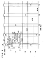
- an engine 1 includes a plurality of (four in the present embodiment) cylinders 1a, and each cylinder 1a is connected through a corresponding intake branch pipe 2 to a common surge tank 3.
- Surge tank 3 is connected through an intake duct 4 to an air cleaner 5, and in intake duct 4, an air flow meter 4a, and a throttle valve 7 driven by an electric motor 6 are arranged.
- Throttle valve 7 has its opening position controlled based on an output signal of an electronic control unit 30, independent from an accelerator pedal 10.
- Each cylinder 1a is coupled to a common exhaust manifold 8, which manifold 8 is coupled to a three-way catalyst converter 9.
- an intake port, an exhaust port, an intake valve and an exhaust valve, not shown are provided, and the intake and exhaust valves are driven to open/close by an actuator or a cam shaft driven in synchronization with the engine.
- a spark plug not shown, an injector 11 for in-cylinder injection for injecting fuel into the cylinder, and an injector 12 for intake manifold injection for injecting fuel into the intake manifold are provided.
- injectors 11 and 12 are each controlled based on an output signal of electronic control unit 30.
- injectors 11 for in-cylinder injection are connected to a common fuel delivery pipe 13, and fuel delivery pipe 13 is connected to an engine-driven high-pressure fuel pump 15, through a check valve 14 that allows passage toward fuel delivery pipe 13.
- the discharge side of high-pressure fuel pump 15 is coupled to the intake side of high-pressure fuel pump 15 through a spill electromagnetic valve 15a, and the smaller the opening position of spill electromagnetic valve 15a, the larger becomes the quantity of fuel supplied from high-pressure fuel pump 15 to fuel delivery pipe 13.
- spill electromagnetic valve 15a is fully open, fuel supply from the high-pressure fuel pump 15 to fuel delivery pipe 13 is stopped. It is noted that spill electromagnetic valve 15a is controlled based on the output signal of electronic control unit 30.
- Each injector 12 for intake manifold injection is connected to a common fuel delivery pipe 16, and fuel delivery pipe 16 and high-pressure fuel pump 15 are connected through a common fuel pressure regulator 17 to an electric-motor-driven low-pressure fuel pump 18. Further, low-pressure fuel pump 18 is connected through a fuel filter 19 to a fuel tank 20. Fuel pressure regulator 17 is adapted such that when the fuel pressure discharged from low-pressure fuel pump 18 becomes higher than a predetermined set fuel pressure, fuel pressure regulator 17 returns part of the fuel discharged from low-pressure fuel pump 18 to fuel tank 20, and therefore, it prevents the pressure of fuel supplied to injector 12 for intake manifold injection and the pressure of fuel supplied to high-pressure fuel pump 15 from becoming higher than the set fuel pressure mentioned above. Further, as shown in Fig.
- an open/close valve 21 is provided between high-pressure fuel pump 15 and fuel pressure regulator 17.
- the open/close valve 21 is normally open, and when it is closed, fuel supply from low-pressure fuel pump 18 to high-pressure fuel pump 15 is stopped. Opening and closing of open/close valve 21 are controlled based on the output signal of electronic control unit 30.
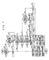
- Electronic control unit 30 is implemented by a digital computer, and includes an ROM (Read Only Memory) 32, an RAM (Random Access Memory) 33, a CPU (micro processor) 34, an input port 35 and an output port 36, which are connected to each other through a bi-directional bus 31.
- Air flow meter 4a generates an output voltage that is in proportion to the quantity of intake air, and the output voltage of air flow meter 4a is input through an AD converter 37 to input port 35.
- a coolant temperature sensor 38 generating an output voltage that is in proportion to the temperature of engine coolant is attached to engine 1, and the output voltage of coolant temperature sensor 38 is input through an AD converter 39 to input port 35.
- a fuel pressure sensor 40 generating an output voltage that is in proportion to the fuel pressure in fuel delivery pipe 13 is attached to fuel delivery pipe 13, and the output voltage of fuel pressure sensor 40 is input through an AD converter 41 to input port 35.
- An air-fuel ratio sensor 42 generating an output voltage that is in proportion to the oxygen concentration in exhaust gas is attached to an exhaust manifold 8 on the upstream side of catalyst 9, and the output voltage of air-fuel ratio sensor 42 is input through an AD converter 43 to input port 35.
- the air-fuel ratio sensor of the present embodiment is a full-range air-fuel ratio sensor (linear air-fuel ratio sensor) that generates an output voltage that is in proportion to the air-fuel ratio of the air-fuel mixture combusted in engine 1.
- an O 2 sensor that detects, in an on-off manner, whether the air-fuel ratio of air-fuel mixture combusted in engine 1 is rich or lean as compared with the theoretical air-fuel ratio may be used.
- Accelerator pedal 10 is connected to an accelerator open position sensor 44 generating an output voltage that is in proportion to the amount of pressing the accelerator pedal 10, and the output voltage of accelerator open position sensor 44 is input through an AD converter 45 to input port 35.
- a crank sensor 46 is connected, which generates an output pulse at every prescribed crank phase of the engine.
- the pulse signal is transmitted to CPU 34 and based on the pulse signal, CPU calculates the engine speed.
- ROM 32 of electronic control unit 30 values of basic fuel injection quantity, timing of fuel injection, timing of ignition and the like are mapped and stored in advance, which values are set in correspondence with the engine speed obtained by crank sensor 46 and engine load obtained by accelerator open position sensor 44.
- a knock sensor 23 which is a vibration sensor, is arranged in a cylinder block of the engine.
- Knock sensor 23 is common to four cylinders 1a, and positioned between central two cylinders 1a among four cylinders 1a arranged in series.
- Knock sensor 23 generates an output voltage that is in proportion to the vibration level of the engine, and the output voltage of knock sensor 23 is input through an AD converter 25 to input port 35.
- the four cylinders 1a arranged in series are respectively referred to as the first cylinder #1, second cylinder #2, third cylinder #3 and fourth cylinder #4 from an end.
- ROM 32 of electronic control unit 30 stores a three-dimensional map such as shown in Fig. 2 , that determines in advance the relation between the basic quantity of fuel injection and the speed and load of the engine 1.
- the entire range of the map that is, the entire operating range of the engine is divided into three ranges, namely, first, second and third ranges R1, R2 and R3.
- the speed is full-speed and the load is low, and only the in-cylinder injection is performed by injector 11 for in-cylinder injection.
- the in-cylinder injection is performed in the compression stroke of the engine, whereby stratified charge combustion is performed.
- stratified charge combustion is performed.
- a relatively rich layer of air-fuel mixture is formed around the spark plug and an air layer is formed therearound, so that satisfactory ignition of air-fuel mixture is assured while the average air-fuel ratio in the entire combustion chamber can be made leaner than the theoretical air-fuel ratio, whereby improved mileage can be attained.
- the speed is low to middle speed and the load is high, and both the port injection by injector 12 for intake manifold injection and in-cylinder injection by injector 11 for in-cylinder injection are performed.
- the in-cylinder injection here is performed in the intake stroke and the compression stroke of the engine. This leads to homogeneous combustion particularly for high load.
- port injection is performed before the intake valve is opened, followed by in-cylinder injection in the intake stroke. Consequently, a large part of the fuel of the total quantity of fuel injection forms a sufficiently homogeneous air-fuel mixture with the taken air in the combustion chamber.
- the air-fuel mixture is mixed with the injected fuel introduced by the in-cylinder injection in the compression stroke and sparked.
- in-cylinder injection By in-cylinder injection, the temperature of intake air and the air-fuel mixture can be lowered, because of latent heat in vaporization of fuel. Therefore, the intake air filling efficiency increases, and the engine output is enhanced. Further, particularly because of the in-cylinder injection in the compression stroke immediately before ignition, knock resistance can also be improved.
- the second range R2 is the range other than the first and third ranges R1 and R3, in which both the port injection by injector12 for intake manifold injection and in-cylinder injection by injector 11 for in-cylinder injection are performed.
- in-cylinder injection is performed only in the intake stroke of the engine. This also realizes homogeneous combustion.
- port injection is performed before the intake valve is opened, followed by the in-cylinder injection in the intake stroke.
- the fuel of total quantity of fuel injection forms, together with the intake air, sufficiently homogeneous air-fuel mixture in the combustion chamber, which air-fuel mixture is sparked by ignition after compression.
- the ratio of injection quantity by injector 11 for in-cylinder injection and injector 12 for intake manifold injection that is, the ratio of fuel injection quantity by injector 11 for in-cylinder injection and injector 12 for intake manifold injection with respect to the total quantity of fuel injection, is determined in advance for every engine speed and load.
- This ratio is represented as injection contribution ratio ⁇ , and the injection contribution ratio ⁇ refers to the ratio of fuel injection quantity injected from injector 11 for in-cylinder injection to the total quantity of fuel injection.
- the ratio of fuel injected from injector 11 for in-cylinder injection is 30% of the total quantity of fuel
- the ratio of fuel injection quantity injected by injector 11 for in-cylinder injection in the intake stroke and the compression stroke, respectively, is determined in advance for every speed and load.
- the ratio is represented as in-cylinder injection contribution ratio ⁇
- the in-cylinder injection contribution ratio ⁇ refers to the ratio of fuel injection quantity injected in the compression stroke to the total fuel injection quantity injected by injector 11 for in-cylinder injection.
- the ratio of fuel injection from injector 11 for in-cylinder injection in the intake stroke is 70% (1- ⁇ )
- the ratio of fuel injection from injector 11 for in-cylinder injection in the compression stroke is 30%.
- the values ⁇ and ⁇ of injection contribution ratios are determined in advance for every speed and load, and stored as a map in ROM 32.
- timings of injection (meaning the start timings of injection) by injector 11 for in-cylinder injection and injector 12 for intake manifold injection are also determined in advance as functions of speed and load for the entire operating range of the engine, and stored as a map in ROM 32.
- injection pressure is also controlled. Specifically, fuel pressure in fuel delivery pipe 13 that corresponds to the injection pressure is determined in advance as a function of speed and load for the entire operating range of the engine, and stored as a map in ROM 32. Feed back control is performed such that the actual fuel pressure detected by fuel pressure sensor 40 matches the target fuel pressure calculated from the map. At this time, the actual fuel pressure is increased or decreased by controlling spill electromagnetic valve 15a.
- electromagnetic control unit 30 determines the quantity and timing of fuel injection by injectors 11 and 12 based on the detected speed and load values and on the plurality of maps mentioned above, and determines the target fuel pressure in fuel delivery pipe 13.
- the time of electric conduction to injectors 11 and 12 that corresponds to the fuel injection quantity is calculated, and by adding the calculated time of electric conduction to the timing of fuel injection, the timing of closing the valves of injectors 11 and 12, that is, the end timing of injection, is determined.
- the actual fuel pressure is set beforehand to the target fuel pressure determined in the above-described manner, and when it comes to the timing of injection by injectors 11 and 12, a driving signal is output to injectors 11 and 12 (that is, injectors 11 and 12 are turned on), so as to open the valve of injectors 11 and 12.
- a driving signal is output to injectors 11 and 12 (that is, injectors 11 and 12 are turned on), so as to open the valve of injectors 11 and 12.
- Such electrically conducted state that is, valve-open state of injectors 11 and 12 is maintained to the injection end timing, and when it comes to the injection end timing, output of the driving signal to the injectors 11 and 12 is stopped (that is, injectors 11 and 12 are turned off), so that injectors 11 and 12 are closed.
- injectors 11 and 12 When injectors 11 and 12 are turned on, the electromagnetic solenoid of each of injectors 11 and 12 is energized, and by electromagnetic attraction generated thereby, the nozzle needle is moved away from the valve seat. Consequently, injection opening of injectors 11 and 12 is opened and injection starts.
- injectors 11 and 12 are turned off, the electromagnetic solenoid is de-energized, so that the nozzle needle comes to be seated back against the valve seat. Consequently, injection opening is closed and injection ends.
- the nozzle needle abutting or hitting the needle stopper and the valve seat as the injector 11 for in-cylinder injection is turned on and off may possibly be detected by knock sensor 23, momentarily heightening the output signal level of the knock sensor 23.
- knock determination is made based on an output signal of knock sensor 23, and in accordance with the result of determination, knock control is performed to adjust spark timing and the like. This will be described in the following.
- electronic control unit 30 When it is determined in knock determination that knocking is occurring, electronic control unit 30 as the knock control means retards the target spark timing by a prescribed amount. On the contrary, when it is determined that knocking is not occurring, electronic control unit 30 gradually advances the target spark timing.
- the target spark timing represents the timing of spark in each cylinder by a crank angle with the compression top dead center of each cylinder used as a reference.
- Electromagnetic unit 30 outputs a spark signal that turns on at a timing indicated by the target spark timing to an igniter (not shown) of each cylinder, for ignition. Thus, the spark timing is adjusted to be close to a limit of knocking occurrence.
- the knock determination will be described next. As shown in Fig. 2 , the entire operating range of the engine is divided beforehand to a low noise range (hereinafter referred to as range A) in which the threshold for knock determination is set to a relatively low value and a high noise range (hereinafter referred to as range B) in which the threshold for knock determination is set to a relatively high value.
- range A low noise range
- range B high noise range
- the range B is the hatched range in which the engine speed is high and the engine load is high.
- the range A is the remaining range.
- the range B partially overlaps with a part of the second range and a part of the third range.
- the knock determination will be outlined, assuming that the operating state of the engine is in range A.
- an output signal K of knock sensor 23 is transmitted to electronic control unit 30, and electronic control unit 30 compares the magnitude of output signal K, that is, the output value, with a knock determination threshold value THA that has been stored beforehand in ROM 32.
- THA a knock determination threshold value
- electromagnetic control unit 30 determines that knocking is occurring.
- the spark timing retarding control as described above is executed.
- the knock determination as such is performed only on the signal K that exists in the gate period, which is the prescribed range of crank phase of the engine.
- the threshold value THA is set by adding a prescribed value MA to a standard background noise level BGNLA of range A.
- the background noise refers to signals output from knock sensor 23 resulting from factors other than knocking, such as combustion in the engine cylinder, vibration of dynamic valves and crank vibration.
- the magnitude of background noise is referred to as the background noise level.
- the background noise level varies in accordance with the operating state of the engine. Generally, the background noise level tends to increase as the engine speed becomes higher and the engine load becomes higher.
- range B is set in advance as a range in which the background noise level is high.
- the background noise level BGNLB is higher than the level BGNLA of range A.
- the knock sensor output value may exceed the threshold value THA because of the background noise itself even if knocking were not occurring, possibly leading to an erroneous determination that knocking is occurring. In other words, range B is prone to such erroneous determination.
- the background noise level is learned in range B in which the background noise level tends to be high, and based on the result, knock determination threshold is increased.
- the knock determination threshold value THB in range B is set and stored, and thereafter in range B, knock determination is made based on the newly set threshold value THB.
- the output value of knock sensor 23 exceeds the threshold value THB (as represented by YB in the figure)
- electronic control unit 30 determines that knocking is occurring. After this determination, spark timing retarding control is performed in the similar manner as described above.
- the added value MB for range B may be or may not be the same as added value MA for range A.
- the knock determination threshold value THB in range B obtained in this manner is larger than the knock determination threshold value THA in range A, and therefore, erroneous determination that knocking is occurring resulting from the background noise itself can be prevented.
- the output signal of knock sensor 23 is treated exclusively as the background noise while background learning is being done, and the knock determination threshold has not yet been determined. Therefore, in this period, knock determination is impossible. Therefore, knock control by which the spark timing is adjusted in accordance with the result of knock determination is not possible either, and as a result, there is a possibility of knocking.
- knocking suppression control means for executing knocking suppression control, which suppresses knocking, by controlling fuel injection by injector 11 for in-cylinder injection or injector 12 for intake manifold injection during background learning. This will be described in the following.
- the ratio of fuel injection by injector 11 for in-cylinder injection with respect to injector 12 for intake manifold injection is increased from the basic ratio of injection determined by the operating state of the engine.
- the in-cylinder injection by injector 11 for in-cylinder injection has functions of lowering intake air temperature in the cylinder because of latent heat in vaporization of fuel, promoting disturbance of air-fuel mixture in the cylinder because of the penetrating force of injected fuel and lowering the temperature of air-fuel mixture in the cylinder during compression and increasing the rate of combustion. These functions are effective to suppress knocking, and therefore, the first approach in which the ratio of in-cylinder injection is increased than the basic ratio of injection is suitable for suppressing knocking.
- the operating state of the engine makes a transition from range A to range B, and from time point t1 to t2, background learning is performed.
- the total quantity of fuel injection Qt, quantity of port injection Qp and quantity of in-cylinder injection Qd are 20, 10 and 10, respectively.
- the total quantity of fuel injection Qt, quantity of port injection Qp and quantity of in-cylinder injection Qd are supposed to be 50, 30 and 20, in accordance with the basic control of fuel injection described above.
- the ratio of in-cylinder injection is increased from the basic ratio of in-cylinder injection in the learning period, so that the total quantity of fuel injection Qt, quantity of port injection Qr and quantity of in-cylinder injection Qd are set to 50, 15 and 35, respectively.
- the injection contribution ratio ⁇ ratio of fuel injection quantity of in-cylinder injection to the total quantity of fuel injection
- the ratio of in-cylinder injection is set to 100% and only the in-cylinder injection is performed.
- the above-described knocking suppressing effect can be fully made use of, and occurrence of knocking can be suppressed to the full extent.
- Range B in which the background learning is done includes the second range R2 in which port injection and in-cylinder injection of intake stroke are performed, and the third range R3 in which port injection and in-cylinder injection of intake and compression strokes are performed.
- the knocking suppression control of the first approach can be performed no matter to which of the second and third ranges R2 and R3 the operating state of the engine enters.
- synchronous injection is executed, in which at least part of the fuel injection period by injector 12 for intake manifold injection is overlapped with the open period of the intake valve.
- the port injected fuel can positively be introduced to the in-cylinder combustion chamber as the fuel can be carried over the flow of intake air generated by the opening of the intake valve or intake port, while preventing adhesion to the port wall surface, whereby similar functions and effects as attained by the in-cylinder injection described above can be obtained.
- the basic injection period is determined such that the injection ends before the intake valve is opened (that is, asynchronous injection).
- the port injection is not yet finished when the intake valve is in the open state, and port injection is performed while the intake valve is open. Port injection ends after opening of the intake valve has started. Therefore, by such synchronous injection during background learning, the injection period can be retarded, and because of the functions described above, knocking can be better suppressed than in the case of basic port injection.
- the ratio of fuel injection quantity in compression stroke to the quantity in intake stroke is increased from the basic ratio of injection quantity determined by the operating state of the engine. Specifically, when the ratio of fuel injection quantity in the compression stroke is increased, in-cylinder injection becomes possible at a timing closer to the timing of combustion, whereby the disturbance of air-fuel mixture in the cylinder can be promoted, rate of combustion can be increased and knocking can be suppressed.
- the third approach of knocking suppression control is on the premise that the in-cylinder injection is performed both in the intake stroke and the compression stroke, and therefore, it is performed in that portion of range B which overlaps with the third range R3.
- the operating state of the engine makes a transition from range A to range B at time point t1, and in the period between t1 and t2, background learning is performed.
- the total quantity of fuel injection Qt, quantity of port injection Qp and quantity of in-cylinder injection of intake stroke Qdi and quantity of in-cylinder injection of compression stroke Qdc are 50, 25, 25 and 0, respectively.
- the total quantity of fuel injection Qt, quantity of port injection Qp and quantity of in-cylinder injection of intake stroke Qdi and quantity of in-cylinder injection of compression stroke Qdc are supposed to be 100, 30, 50 and 20, in accordance with the basic fuel injection control described above.
- the ratio of in-cylinder injection of the compression stroke is increased from the basic ratio of in-cylinder injection of the compression stroke, and the total quantity of fuel injection Qt, quantity of port injection Qp and quantity of in-cylinder injection of intake stroke Qdi and quantity of in-cylinder injection of compression stroke Qdc are 100, 30, 40 and 30, respectively.
- One or two or more of the first to third approaches may be selected and combined, as needed.
- knocking suppression control By the knocking suppression control described above, knocking during background learning can be suppressed. It is noted, however, that when such knocking suppression control is performed, the quantity of fuel injection for the in-cylinder injection is changed from the basic value, possibly resulting in the following problem.
- the injector for injecting fuel is structured such that by energizing the electromagnetic solenoid, the nozzle needle is driven away from the valve seat and the valve is opened and fuel injection starts, and by deenergizing the electromagnetic solenoid, the nozzle needle comes to be seated against the valve seat and fuel injection ends.
- the nozzle needle when the valve is opened, the nozzle needle abuts the valve stopper and generates vibration by the impact at that time, and when the valve is closed, the nozzle needle is seated against the valve seat and generates vibration by the impact at that time.
- vibrations generated at the time of opening and closing the valve of the injector may ride as noise on the output signal of the knock sensor.
- injector 11 for in-cylinder injection is positioned close to the knock sensor 23 and the vibration generated at injector 11 for in-cylinder injection tends to be directly transmitted to knock sensor 23 through the cylinder block, and therefore, the influence of noise generated by the operation of injector 11 for in-cylinder injection (hereinafter referred to as injector noise) tends to be more significant than in a port-injection type internal combustion engine.
- the object is absolutely to learn the background noise level in the normal or basic state, and therefore, when the injector noise is riding on the background noise in the basic state, learning of the basic state as such is desirable.
- fixing means for fixing the start timing or end timing of fuel injection by injector 11 for in-cylinder injection during the background learning is provided. This will be described in the following.
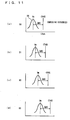
- Fig. 6 shows an operation of the internal combustion engine in accordance with the present embodiment, in which the abscissa represents the crank angle, indicating a full cylinder cycle from 0° at the intake top dead center of the first cylinder #1 to 720°. From the upper portion of the figure, operations or strokes of the first cylinder #1, third cylinder #3, fourth cylinder #4 and the second cylinder #2 are shown in the order of ignition. Here, “intake” represents the intake stroke, and the star mark represents the spark timing.
- the gate signal is originally for determining the period in which knock determination is made, and the knock determination is made by referring to the output signal of knock sensor 34 while the gate signal is on.
- This period is also referred to as the gate period meaning that the gate for obtaining the output value of knock sensor 34 is open.
- the output value of knock sensor 34 related to the background learning is obtained in the gate period.
- setting of the on timing and off timing of the gate signal is done with reference to a map stored in advance in ROM 32 of electronic control unit 30.
- the map is defined as a three-dimensional map in relation to the engine speed and the engine load. It is noted, however, that the on timing and the off timing of the gate signal.may be set as constant timings. In the shown example, the on timing and the off timing of the gate signal are set at timings before and after the spark timing of each cylinder, as knocking is likely near the spark timing of each cylinder.
- first cylinder #1 Various patterns of in-cylinder injection executed by injector 11 for in-cylinder injection are shown in the column of first cylinder #1 of the figure. As fuel injection control is performed for each cylinder, similar patterns are observed on other cylinders. Here, only the patterns of first cylinder #1 are shown for simplicity. These patterns are all in the learning period immediately after the operating state of the engine made transition to the range B.
- T represents injection period
- S represents injection start timing
- E represents injection end timing, respectively.
- in-cylinder injection of the first cylinder #1 is done in the intake stroke, and the problem is whether the injection start timing S or injection end timing E is within the gate period Tg4 opened for ignition of the fourth cylinder #4 or within the gate period Tg2 opened for ignition of the second cylinder #2.
- the first approach represented by G1 will be described first.
- the first approach focuses on the relation between the injection start timing S and the gate period Tg4.
- T11 represents the injection period determined in accordance with the basic fuel injection control based on the operating state of the engine, and only the injection start timing S11 thereof is within the gate period Tg4.
- the quantity of in-cylinder injection at one time may sometimes be increased and in that case, the injection period must also be made longer.
- the injection start timing T12 is fixed to be the same as the basic injection start timing S11 and, instead, the injection end timing E12 that is originally not within the gate period Tg4 is retarded from the basic injection end timing E11, as can be seen from injection period T12. In this manner, the start timing for in-cylinder injection is fixed in the background learning.
- the injection period is made longer not by advancing the injection start timing S 13 to be earlier than the basic injection start timing S 11, as shown by injection period T13.
- the injection start timing S13 would be out of the gate period Tg4, and it is possible that the background noise level differs from that in the basic state.
- the injection period is to be made longer as requested by the knocking suppression control and the basic injection start timing is within the gate period, such a state is maintained after the period is made longer.
- the injection start timing is fixed, to be the same even after the period is made longer.
- the background noise including the injector noise generated at the injection start timing which is the same as in the basic state, can be obtained.
- accurate background learning becomes possible.
- T21 represents the injection period determined in accordance with the basic fuel injection control based on the operating state of the engine, and only the injection end timing E21 thereof is within the gate period Tg2.
- the quantity of in-cylinder injection at one time may sometimes be increased and in that case, the injection period must also be made longer.
- the injection end timing E22 is fixed to be the same as the basic injection end timing E21 and, instead, the injection start timing S22 that is originally not within the gate period Tg2 is advanced from the basic injection start timing S21, as can be seen from injection period T22. In this manner, the start timing for in-cylinder injection is fixed in the background learning.
- the injection period is made longer not by retarding the injection end timing E23 to be later than the basic injection end timing E21, as shown by injection period T23.
- the injection end timing E23 would be out of the gate period Tg2, and it is possible that the background noise level differs from that in the basic state.
- the injection period is to be made longer as requested by the knocking suppression control and the basic injection end timing is within the gate period, such a state is maintained after the period is made longer.
- the injection end timing is fixed, to be the same even after the period is made longer.
- the background noise including the injector noise generated at the injection end timing that is the same as in the basic state can be obtained.
- accurate background learning becomes possible.
- T31 represents the injection period determined in accordance with the basic fuel injection control based on the operating state of the engine.
- the injection start timing S31 is within the gate period Tg4, and the injection end timing E31 is within the gate period Tg2.
- the injection start timing S31 and the injection end timing S31 must be kept within the gate periods Tg4 and Tg2, respectively. Therefore, in the third approach, when the in-cylinder injection quantity is to be made larger as requested by the knocking suppression control, the injection start timing and the injection end timing are maintained at the basic timings, that is, the injection start timing and the injection end timing are maintained within the gate periods, and the fuel pressure of the fuel to be injected by injector 11 for in-cylinder injection is increased, so that the quantity of in-cylinder injection is increased without changing the injection period.
- the fuel pressure of injector 11 for in-cylinder injection (that is, the pressure in fuel delivery pipe 13) is under feedback-control to match the target value on the map, based on the operating state of the engine. Therefore, by changing the basic target fuel pressure determined in this manner to a higher value, that is, a value that can attain comparable fuel injection quantity within the same injection period, knocking suppression control that increases the quantity of in-cylinder injection without changing the injection start timing S31 and injection end timing E31 can be realized.
- the injection end timing E or injection start timing S that is not fixed reaches a pre-set guard and it becomes impossible to further retard or advance the end timing or the start timing. In that case also, by increasing the fuel pressure, desired quantity of in-cylinder injection can be attained within a limited injection period.
- the value of a learning counter CKCSG is set to 0 in S102, the injection start timing, injection end timing and target fuel pressure in fuel delivery pipe 13 are set to the basic values in accordance with the basic control in S103, S 104 and S105, respectively, execution of knocking suppression control is terminated in S106 and the process ends.
- the background learning area AREA refers to a smaller area in range B, distinguished by whether the gate period described above includes only the injection start timing of in-cylinder injection, only the injection end timing, both timings or neither of the timings.
- the background learning area AREA is B1.
- the last background learning area AREA and the present background learning are AREA are compared so as to determines whether the area has been changed or not, and as the background noise level is set for every background learning area AREA (see Fig. 11 ).
- the background noise tends to vary dependent on how many factors of background noise generation (such as start and end of injection) are included in the gate period. By setting the background noise level for each of the areas, it becomes possible to set accurate levels for respective areas and to perform accurate knock determination for respective areas.
- the initial value n of learning counter CKCSG defines the number of obtaining the output values of knock sensor 23 in the gate period and preferably, at least 10 is set as the value, as described above.
- the data is obtained by the number of times equal to the initial value n for every background learning area AREA, and based on the data, the background noise level is set.
- the period in which the value of learning counter attains from the initial value n to 0 is the learning period.
- Fig. 8 is a flow chart representing such a process. This process is also executed by electronic control unit 30 in synchronization with the process shown in Fig. 7 (namely, in the period corresponding to the crank angle of 180°).
- the on timing and off timing of the gate signal are set.
- the setting is done with reference to maps stored in advance, based on the engine speed and engine load.
- the gate period is set in this manner, and when it comes to the on timing of the gate signal, the gate signal is turned on in S202, and the gate is opened.
- the flow proceeds to S203, in which the peak-holding of the output signal of knock sensor 34 is executed. The peak-holding is performed until it comes to the off timing of the gate signal and the gate signal is turned off, that is, until the gate is closed, in S204.
- the peak-holding is done in such a manner that every time the output value of knock sensor 34 attains the maximum value after the gate signal is turned on, the value is updated. In this manner, when the gate signal is turned off, one peak hold value VKPEAK can be found for the just finished gate period. The thus found peak hold value VKPEAK is stored in RAM 33 of electronic control unit 30 in S205. Then the process ends.
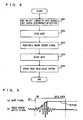
- n peak hold values VKPEAK are stored. Therefore, in the process of Fig. 10 , a method is adopted in which distribution of the n peak hold values VKPEAK is found, and the median thereof is taken as the background level learning value.
- the read n peak hold values VKPEAK are each subjected to logarithmic transformation to find n logarithmically transformed values LVpk, and the distribution DS such as shown in Fig. 11(a) of these logarithmically transformed values LVpk is found.
- the median Vm of the distribution DS is taken as the background learning value, and stored in RAM 33.
- the abscissa is in logarithm, and therefore, in actual noise determination, the knock determination threshold value THB subjected to logarithmic transformation is used, and knock determination is made by the comparison between the knock determination threshold value THB and the logarithmically transformed knock sensor output value.
- the range in which the background noise is relatively high and therefore the knock determination threshold value should also be set to a relatively high value has been selected as range B in which background learning is done. It is possible, however, to select the range in which the basic start timing or end timing of in-cylinder injection is always within the gate period as the range B. The reason for this is that matching between the injection start timing or end timing and the gate period is one factor that causes higher background noise.
- the range B is divided into areas B 1, B2 and B3, and accordingly, three values are set as the background learning values.
- logarithmically transformed values LVpk are calculated, and the median Vm of the distribution of logarithmically transformed values LVpk is used as the background noise level learning value. It is possible, however, to more simply use an average of the plurality of sensor output values as the background noise level learning value.
Claims (1)
- Als Zweifacheinspritzungs-Motor ausgelegter Verbrennungsmotor (1) mit einem Injektor (11) für eine Zylindereinspritzung und einem Injektor (12) für eine Saugrohreinspritzung, aufweisend:einen Klopfsensor (23);einen Lernabschnitt, der einen Hintergrund-Geräuschpegel auf der Basis eines Ausgangssignals vom Klopfsensor lernt; undeinen Fixierungsabschnitt (S112, S117), der, während er den Hintergrund-Geräuschpegel lernt, zumindest einen Startzeitpunkt und/oder einen Endzeitpunkt der Kraftstoffeinspritzung durch den Injektor für eine Zylindereinspritzung auf einen vorbestimmten Zeitpunkt, in einem vorbestimmten Betriebsbereich des Motors, festlegt, wobeider vorbestimmte Zeitpunkt innerhalb einer Gate-Periode zum Lernen des Hintergrundgeräuschpegels liegt.
Applications Claiming Priority (2)
| Application Number | Priority Date | Filing Date | Title |
|---|---|---|---|
| JP2005000187A JP4492351B2 (ja) | 2005-01-04 | 2005-01-04 | デュアル噴射型内燃機関 |
| EP05819562A EP1834072B1 (de) | 2005-01-04 | 2005-12-16 | Verbrennungsmotor mit doppeleinspritzung |
Related Parent Applications (2)
| Application Number | Title | Priority Date | Filing Date |
|---|---|---|---|
| EP05819562A Division EP1834072B1 (de) | 2005-01-04 | 2005-12-16 | Verbrennungsmotor mit doppeleinspritzung |
| EP05819562.9 Division | 2005-12-16 |
Publications (2)
| Publication Number | Publication Date |
|---|---|
| EP2110534A1 EP2110534A1 (de) | 2009-10-21 |
| EP2110534B1 true EP2110534B1 (de) | 2011-08-31 |
Family
ID=36013382
Family Applications (2)
| Application Number | Title | Priority Date | Filing Date |
|---|---|---|---|
| EP09009238A Expired - Fee Related EP2110534B1 (de) | 2005-01-04 | 2005-12-16 | Verbrennungsmotor mit Doppeleinspritzung |
| EP05819562A Expired - Fee Related EP1834072B1 (de) | 2005-01-04 | 2005-12-16 | Verbrennungsmotor mit doppeleinspritzung |
Family Applications After (1)
| Application Number | Title | Priority Date | Filing Date |
|---|---|---|---|
| EP05819562A Expired - Fee Related EP1834072B1 (de) | 2005-01-04 | 2005-12-16 | Verbrennungsmotor mit doppeleinspritzung |
Country Status (6)
| Country | Link |
|---|---|
| US (2) | US7377255B2 (de) |
| EP (2) | EP2110534B1 (de) |
| JP (1) | JP4492351B2 (de) |
| CN (1) | CN101151446B (de) |
| DE (1) | DE602005020506D1 (de) |
| WO (1) | WO2006073062A1 (de) |
Cited By (1)
| Publication number | Priority date | Publication date | Assignee | Title |
|---|---|---|---|---|
| DE102012207733B4 (de) | 2012-05-09 | 2024-05-02 | Robert Bosch Gmbh | Verfahren und Vorrichtung zur Erkennung eines Klopfens eines Verbrennungsmotors |
Families Citing this family (38)
| Publication number | Priority date | Publication date | Assignee | Title |
|---|---|---|---|---|
| JP4353216B2 (ja) * | 2006-08-04 | 2009-10-28 | トヨタ自動車株式会社 | 筒内噴射式火花点火内燃機関 |
| JP5018026B2 (ja) * | 2006-11-09 | 2012-09-05 | トヨタ自動車株式会社 | 車両用駆動装置の制御装置 |
| WO2008067406A2 (en) * | 2006-11-28 | 2008-06-05 | Transocean Sedco Forex Ventures Limited | Through-hull mooring system |
| JP2008202493A (ja) | 2007-02-20 | 2008-09-04 | Yamaha Motor Co Ltd | 燃料噴射制御装置、エンジンおよび鞍乗型車両 |
| DE102007019641A1 (de) * | 2007-04-26 | 2008-10-30 | Robert Bosch Gmbh | Verfahren und Vorrichtung zur Steuerung einer Brennkraftmaschine |
| JP4349451B2 (ja) * | 2007-08-23 | 2009-10-21 | 株式会社デンソー | 燃料噴射制御装置およびそれを用いた燃料噴射システム |
| US20090078027A1 (en) * | 2007-09-25 | 2009-03-26 | Lycoming Engines, A Division Of Avco Corporation | Aircraft engine cylinder assembly knock detection and suppression system |
| US7904231B2 (en) * | 2008-07-22 | 2011-03-08 | GM Global Technology Operations LLC | Method for controlling combustion noise in a compression-ignition engine |
| US8291888B2 (en) * | 2008-07-24 | 2012-10-23 | Honda Motor Co., Ltd. | Speed dependent knock control |
| US20100038236A1 (en) * | 2008-08-18 | 2010-02-18 | Alex Rivera | Hydrogen-from-water on-demand supplemental vehicle fuel electrolyzer system |
| FR2936017B1 (fr) * | 2008-09-18 | 2015-09-04 | Inst Francais Du Petrole | Procede de controle de la combustion d'un melange carbure pour un moteur a combustion interne a allumage commande, notamment pour un moteur suralimente |
| JP5333172B2 (ja) * | 2009-11-24 | 2013-11-06 | トヨタ自動車株式会社 | 内燃機関の制御装置 |
| JP5508834B2 (ja) * | 2009-12-22 | 2014-06-04 | 日産自動車株式会社 | 内燃機関のノック判定装置 |
| DE102010061810A1 (de) | 2010-11-23 | 2012-05-24 | Robert Bosch Gmbh | Verfahren zum Betreiben eines Kraftstoffsystems einer Brennkraftmaschine |
| WO2012131943A1 (ja) * | 2011-03-30 | 2012-10-04 | トヨタ自動車株式会社 | 内燃機関の燃料噴射制御装置 |
| WO2013061425A1 (ja) | 2011-10-26 | 2013-05-02 | トヨタ自動車 株式会社 | 内燃機関の燃料噴射制御装置 |
| WO2013061426A1 (ja) | 2011-10-26 | 2013-05-02 | トヨタ自動車 株式会社 | 内燃機関の燃料噴射制御装置 |
| JP6123175B2 (ja) * | 2012-06-29 | 2017-05-10 | マツダ株式会社 | 直噴エンジンの燃料噴射装置 |
| US9556784B2 (en) * | 2013-03-14 | 2017-01-31 | Ford Global Technologies, Llc | Method and system for vacuum control |
| US9255541B2 (en) | 2013-04-01 | 2016-02-09 | Ford Global Technologies, Llc | Method and system for engine control |
| US9297329B2 (en) * | 2013-04-01 | 2016-03-29 | Ford Global Technologies, Llc | Method and system for engine control |
| JP6098477B2 (ja) * | 2013-11-07 | 2017-03-22 | トヨタ自動車株式会社 | 火花点火式内燃機関の制御システム |
| JP6090594B2 (ja) * | 2014-06-24 | 2017-03-08 | トヨタ自動車株式会社 | 内燃機関の燃料噴射システム |
| CN106224107A (zh) * | 2016-08-23 | 2016-12-14 | 海博瑞德(北京)汽车技术有限公司 | 32位多点喷射发动机控制单元 |
| CN106930845B (zh) * | 2017-04-12 | 2019-08-27 | 潍柴西港新能源动力有限公司 | 一种燃气发动机爆震标定方法 |
| IT201700050454A1 (it) * | 2017-05-10 | 2018-11-10 | Magneti Marelli Spa | Metodo per il controllo di un dispositivo attuatore per un motore a combustione interna |
| JP6555323B2 (ja) * | 2017-11-10 | 2019-08-07 | マツダ株式会社 | 圧縮着火式エンジンの制御装置 |
| US10995683B2 (en) * | 2018-04-30 | 2021-05-04 | Woodward, Inc. | Acoustic knock detection in dual-fuel engines |
| US10746153B2 (en) | 2018-05-21 | 2020-08-18 | Ford Global Technologies, Llc | Method and system for adjusting engine knock background noise of a variable displacement engine |
| US10975828B2 (en) | 2018-05-21 | 2021-04-13 | Ford Global Technologies, Llc | Method and system for adjusting engine knock background noise levels |
| US11204011B2 (en) | 2018-05-21 | 2021-12-21 | Ford Global Technologies, Llc | Method and system for variable displacement engine knock control |
| US11255288B2 (en) * | 2018-05-23 | 2022-02-22 | Ford Global Technologies, Llc | Method and system for determining engine knock background noise levels |
| US10830163B2 (en) * | 2018-09-05 | 2020-11-10 | Ford Global Technologies, Llc | Method and system for learning contributions to an engine knock background noise level |
| US11073093B2 (en) * | 2018-11-19 | 2021-07-27 | Ford Global Technologies, Llc | Method and system for learning contributions of engine knock background noise for a variable displacement engine |
| DE102019000239A1 (de) | 2019-01-14 | 2020-07-16 | Daimler Ag | Verfahren zum Betreiben einer Verbrennungskraftmaschine, insbesondere eines Kraftfahrzeugs |
| CN111980817A (zh) * | 2019-05-21 | 2020-11-24 | 上海汽车集团股份有限公司 | 一种发动机控制方法及装置 |
| FR3102212B1 (fr) * | 2019-10-16 | 2022-03-18 | Psa Automobiles Sa | Moteur à combustion interne à essence à allumage par compression |
| JP2023133802A (ja) * | 2022-03-14 | 2023-09-27 | トヨタ自動車株式会社 | 内燃機関の制御装置 |
Family Cites Families (20)
| Publication number | Priority date | Publication date | Assignee | Title |
|---|---|---|---|---|
| JPH02191819A (ja) | 1988-04-07 | 1990-07-27 | Mazda Motor Corp | ロータリピストンエンジンの燃料供給装置 |
| JPH0653728A (ja) | 1992-07-31 | 1994-02-25 | Sony Corp | 送信及び/又は受信アンテナ |
| JP3668497B2 (ja) * | 1992-09-30 | 2005-07-06 | 株式会社日立製作所 | 内燃機関のノッキング検出方法及び点火時期制御方法 |
| JP2964826B2 (ja) * | 1993-03-17 | 1999-10-18 | 松下電器産業株式会社 | ノッキング検出装置 |
| JP3317166B2 (ja) | 1996-11-26 | 2002-08-26 | トヨタ自動車株式会社 | 内燃機関のノッキング判定装置 |
| GB2343220A (en) * | 1998-10-26 | 2000-05-03 | Ford Motor Co | Internal combustion engine knock detection |
| JP3193692B2 (ja) * | 1998-11-13 | 2001-07-30 | ダイハツ工業株式会社 | 内燃機関のノック判定用学習値の学習方法 |
| JP2002227697A (ja) * | 2001-01-31 | 2002-08-14 | Mitsubishi Motors Corp | 内燃機関の燃料噴射装置 |
| JP2003013785A (ja) | 2001-06-28 | 2003-01-15 | Nissan Motor Co Ltd | 直噴火花点火式内燃機関の制御装置 |
| JP3893909B2 (ja) | 2001-06-28 | 2007-03-14 | 日産自動車株式会社 | 直噴火花点火式内燃機関の制御装置 |
| JP3521894B2 (ja) * | 2001-09-17 | 2004-04-26 | トヨタ自動車株式会社 | 可変バルブタイミング装置付き内燃機関の制御装置 |
| JP4178386B2 (ja) * | 2002-03-28 | 2008-11-12 | 株式会社デンソー | 内燃機関のノッキング抑制制御装置 |
| JP4211296B2 (ja) * | 2002-06-12 | 2009-01-21 | 日産自動車株式会社 | 内燃機関のノック制御装置 |
| JP3900088B2 (ja) * | 2003-02-20 | 2007-04-04 | トヨタ自動車株式会社 | 内燃機関のノック判定期間の設定方法、燃料噴射時期の設定方法、及び内燃機関の制御装置 |
| JP2004270583A (ja) * | 2003-03-10 | 2004-09-30 | Toyota Motor Corp | 内燃機関の燃料噴射装置 |
| JP2004278461A (ja) | 2003-03-18 | 2004-10-07 | Toyota Motor Corp | 内燃機関のノッキング制御装置 |
| JP2004308618A (ja) | 2003-04-10 | 2004-11-04 | Toyota Motor Corp | 圧縮比変更機構を備えた内燃機関および内燃機関の制御方法 |
| JP4052230B2 (ja) | 2003-11-12 | 2008-02-27 | トヨタ自動車株式会社 | 内燃機関のノッキング判定装置 |
| JP4036198B2 (ja) | 2004-03-03 | 2008-01-23 | トヨタ自動車株式会社 | 内燃機関の燃料噴射制御装置 |
| JP2006037912A (ja) * | 2004-07-29 | 2006-02-09 | Toyota Motor Corp | 内燃機関のノッキング判定装置 |
-
2005
- 2005-01-04 JP JP2005000187A patent/JP4492351B2/ja not_active Expired - Fee Related
- 2005-12-16 DE DE602005020506T patent/DE602005020506D1/de active Active
- 2005-12-16 WO PCT/JP2005/023556 patent/WO2006073062A1/en active Application Filing
- 2005-12-16 US US11/304,539 patent/US7377255B2/en not_active Expired - Fee Related
- 2005-12-16 EP EP09009238A patent/EP2110534B1/de not_active Expired - Fee Related
- 2005-12-16 CN CN2005800459312A patent/CN101151446B/zh not_active Expired - Fee Related
- 2005-12-16 EP EP05819562A patent/EP1834072B1/de not_active Expired - Fee Related
-
2008
- 2008-04-25 US US12/149,078 patent/US7844389B2/en not_active Expired - Fee Related
Cited By (1)
| Publication number | Priority date | Publication date | Assignee | Title |
|---|---|---|---|---|
| DE102012207733B4 (de) | 2012-05-09 | 2024-05-02 | Robert Bosch Gmbh | Verfahren und Vorrichtung zur Erkennung eines Klopfens eines Verbrennungsmotors |
Also Published As
| Publication number | Publication date |
|---|---|
| CN101151446A (zh) | 2008-03-26 |
| WO2006073062A1 (en) | 2006-07-13 |
| JP2006188973A (ja) | 2006-07-20 |
| US7844389B2 (en) | 2010-11-30 |
| EP1834072A1 (de) | 2007-09-19 |
| CN101151446B (zh) | 2010-09-08 |
| US7377255B2 (en) | 2008-05-27 |
| US20060144365A1 (en) | 2006-07-06 |
| JP4492351B2 (ja) | 2010-06-30 |
| US20080208439A1 (en) | 2008-08-28 |
| EP1834072B1 (de) | 2010-04-07 |
| DE602005020506D1 (de) | 2010-05-20 |
| EP2110534A1 (de) | 2009-10-21 |
Similar Documents
| Publication | Publication Date | Title |
|---|---|---|
| EP2110534B1 (de) | Verbrennungsmotor mit Doppeleinspritzung | |
| US6981487B2 (en) | Knocking determination apparatus for internal combustion engine | |
| US7286924B2 (en) | Knocking determining apparatus of internal combustion engine | |
| US7055500B2 (en) | Ignition timing control apparatus for internal combustion engine | |
| US7207315B2 (en) | Device and method for controlling internal combustion engine | |
| JP5809796B2 (ja) | 内燃機関の燃料噴射制御装置 | |
| EP1443197B1 (de) | Regelsystem für die Direkteinspritzung des Kraftstoffs | |
| US6925987B2 (en) | Method for setting a knock determination period in an internal combustion engine, method for setting a fuel injection timing in an internal combustion engine, and control apparatus for an internal combustion engine | |
| CN112166245B (zh) | 内燃机的控制装置以及内燃机的控制方法 | |
| US20160040618A1 (en) | Control of an internal combustion engine | |
| JP2006194098A (ja) | 内燃機関の燃料噴射制御装置 | |
| JP3893909B2 (ja) | 直噴火花点火式内燃機関の制御装置 | |
| JP2007154853A (ja) | 火花点火式直噴内燃機関の制御装置 | |
| WO2013061425A1 (ja) | 内燃機関の燃料噴射制御装置 | |
| WO2013061424A1 (ja) | 内燃機関の燃料噴射制御装置 | |
| JP4640526B2 (ja) | デュアル噴射型内燃機関 | |
| JP5282636B2 (ja) | 内燃機関の制御装置 | |
| JP2006316667A (ja) | 複数燃料内燃機関のノッキング判定装置 | |
| JP4200963B2 (ja) | 内燃機関の制御装置 | |
| JP2006132399A (ja) | 過給機付エンジンの制御装置および制御方法 | |
| US11421623B2 (en) | Internal combustion engine control device | |
| JP5195383B2 (ja) | 筒内直接噴射式火花点火内燃機関 | |
| JP2006132400A (ja) | 内燃機関の燃料噴射制御方法 | |
| JP2022093782A (ja) | 内燃機関の制御方法および制御装置 |
Legal Events
| Date | Code | Title | Description |
|---|---|---|---|
| PUAI | Public reference made under article 153(3) epc to a published international application that has entered the european phase |
Free format text: ORIGINAL CODE: 0009012 |
|
| AC | Divisional application: reference to earlier application |
Ref document number: 1834072 Country of ref document: EP Kind code of ref document: P |
|
| AK | Designated contracting states |
Kind code of ref document: A1 Designated state(s): DE FR IT |
|
| 17P | Request for examination filed |
Effective date: 20090715 |
|
| GRAP | Despatch of communication of intention to grant a patent |
Free format text: ORIGINAL CODE: EPIDOSNIGR1 |
|
| RIC1 | Information provided on ipc code assigned before grant |
Ipc: F02D 35/02 20060101AFI20110113BHEP Ipc: G01L 23/22 20060101ALI20110113BHEP |
|
| GRAS | Grant fee paid |
Free format text: ORIGINAL CODE: EPIDOSNIGR3 |
|
| GRAA | (expected) grant |
Free format text: ORIGINAL CODE: 0009210 |
|
| AC | Divisional application: reference to earlier application |
Ref document number: 1834072 Country of ref document: EP Kind code of ref document: P |
|
| AK | Designated contracting states |
Kind code of ref document: B1 Designated state(s): DE FR IT |
|
| REG | Reference to a national code |
Ref country code: DE Ref legal event code: R096 Ref document number: 602005029849 Country of ref document: DE Effective date: 20111110 |
|
| PLBE | No opposition filed within time limit |
Free format text: ORIGINAL CODE: 0009261 |
|
| STAA | Information on the status of an ep patent application or granted ep patent |
Free format text: STATUS: NO OPPOSITION FILED WITHIN TIME LIMIT |
|
| 26N | No opposition filed |
Effective date: 20120601 |
|
| REG | Reference to a national code |
Ref country code: DE Ref legal event code: R097 Ref document number: 602005029849 Country of ref document: DE Effective date: 20120601 |
|
| REG | Reference to a national code |
Ref country code: DE Ref legal event code: R084 Ref document number: 602005029849 Country of ref document: DE Effective date: 20120924 |
|
| PGFP | Annual fee paid to national office [announced via postgrant information from national office to epo] |
Ref country code: DE Payment date: 20131211 Year of fee payment: 9 |
|
| PGFP | Annual fee paid to national office [announced via postgrant information from national office to epo] |
Ref country code: FR Payment date: 20131209 Year of fee payment: 9 Ref country code: IT Payment date: 20131223 Year of fee payment: 9 |
|
| REG | Reference to a national code |
Ref country code: DE Ref legal event code: R119 Ref document number: 602005029849 Country of ref document: DE |
|
| REG | Reference to a national code |
Ref country code: FR Ref legal event code: ST Effective date: 20150831 |
|
| PG25 | Lapsed in a contracting state [announced via postgrant information from national office to epo] |
Ref country code: DE Free format text: LAPSE BECAUSE OF NON-PAYMENT OF DUE FEES Effective date: 20150701 |
|
| PG25 | Lapsed in a contracting state [announced via postgrant information from national office to epo] |
Ref country code: FR Free format text: LAPSE BECAUSE OF NON-PAYMENT OF DUE FEES Effective date: 20141231 |
|
| PG25 | Lapsed in a contracting state [announced via postgrant information from national office to epo] |
Ref country code: IT Free format text: LAPSE BECAUSE OF NON-PAYMENT OF DUE FEES Effective date: 20141216 |