EP2108935A1 - Dispositif de détermination de cliquetis de moteur à combustion interne et système de commande d'ignition le comportant - Google Patents
Dispositif de détermination de cliquetis de moteur à combustion interne et système de commande d'ignition le comportant Download PDFInfo
- Publication number
- EP2108935A1 EP2108935A1 EP09167082A EP09167082A EP2108935A1 EP 2108935 A1 EP2108935 A1 EP 2108935A1 EP 09167082 A EP09167082 A EP 09167082A EP 09167082 A EP09167082 A EP 09167082A EP 2108935 A1 EP2108935 A1 EP 2108935A1
- Authority
- EP
- European Patent Office
- Prior art keywords
- waveform
- vibration
- engine
- knock
- internal combustion
- Prior art date
- Legal status (The legal status is an assumption and is not a legal conclusion. Google has not performed a legal analysis and makes no representation as to the accuracy of the status listed.)
- Withdrawn
Links
Images


Classifications
-
- G—PHYSICS
- G01—MEASURING; TESTING
- G01L—MEASURING FORCE, STRESS, TORQUE, WORK, MECHANICAL POWER, MECHANICAL EFFICIENCY, OR FLUID PRESSURE
- G01L23/00—Devices or apparatus for measuring or indicating or recording rapid changes, such as oscillations, in the pressure of steam, gas, or liquid; Indicators for determining work or energy of steam, internal-combustion, or other fluid-pressure engines from the condition of the working fluid
- G01L23/22—Devices or apparatus for measuring or indicating or recording rapid changes, such as oscillations, in the pressure of steam, gas, or liquid; Indicators for determining work or energy of steam, internal-combustion, or other fluid-pressure engines from the condition of the working fluid for detecting or indicating knocks in internal-combustion engines; Units comprising pressure-sensitive members combined with ignitors for firing internal-combustion engines
- G01L23/221—Devices or apparatus for measuring or indicating or recording rapid changes, such as oscillations, in the pressure of steam, gas, or liquid; Indicators for determining work or energy of steam, internal-combustion, or other fluid-pressure engines from the condition of the working fluid for detecting or indicating knocks in internal-combustion engines; Units comprising pressure-sensitive members combined with ignitors for firing internal-combustion engines for detecting or indicating knocks in internal combustion engines
- G01L23/225—Devices or apparatus for measuring or indicating or recording rapid changes, such as oscillations, in the pressure of steam, gas, or liquid; Indicators for determining work or energy of steam, internal-combustion, or other fluid-pressure engines from the condition of the working fluid for detecting or indicating knocks in internal-combustion engines; Units comprising pressure-sensitive members combined with ignitors for firing internal-combustion engines for detecting or indicating knocks in internal combustion engines circuit arrangements therefor
-
- F—MECHANICAL ENGINEERING; LIGHTING; HEATING; WEAPONS; BLASTING
- F02—COMBUSTION ENGINES; HOT-GAS OR COMBUSTION-PRODUCT ENGINE PLANTS
- F02P—IGNITION, OTHER THAN COMPRESSION IGNITION, FOR INTERNAL-COMBUSTION ENGINES; TESTING OF IGNITION TIMING IN COMPRESSION-IGNITION ENGINES
- F02P5/00—Advancing or retarding ignition; Control therefor
- F02P5/04—Advancing or retarding ignition; Control therefor automatically, as a function of the working conditions of the engine or vehicle or of the atmospheric conditions
- F02P5/145—Advancing or retarding ignition; Control therefor automatically, as a function of the working conditions of the engine or vehicle or of the atmospheric conditions using electrical means
- F02P5/15—Digital data processing
- F02P5/152—Digital data processing dependent on pinking
- F02P5/1521—Digital data processing dependent on pinking with particular means during a transient phase, e.g. starting, acceleration, deceleration, gear change
-
- Y—GENERAL TAGGING OF NEW TECHNOLOGICAL DEVELOPMENTS; GENERAL TAGGING OF CROSS-SECTIONAL TECHNOLOGIES SPANNING OVER SEVERAL SECTIONS OF THE IPC; TECHNICAL SUBJECTS COVERED BY FORMER USPC CROSS-REFERENCE ART COLLECTIONS [XRACs] AND DIGESTS
- Y02—TECHNOLOGIES OR APPLICATIONS FOR MITIGATION OR ADAPTATION AGAINST CLIMATE CHANGE
- Y02T—CLIMATE CHANGE MITIGATION TECHNOLOGIES RELATED TO TRANSPORTATION
- Y02T10/00—Road transport of goods or passengers
- Y02T10/10—Internal combustion engine [ICE] based vehicles
- Y02T10/40—Engine management systems
Definitions
- the present invention relates generally to knock determination devices and ignition control systems including the same and particularly to such devices and systems that determine from a waveform of vibration of an internal combustion engine whether the engine knocks.
- Japanese Patent Laying-Open No. 2000-205096 discloses an internal combustion engine knock detection device provided for an internal combustion engine and capable of detecting knocking with high precision.
- the knock detection device disclosed in this document includes a knock detector detecting the internal combustion engine's mechanical vibration to output a knock signal, and a knock determiner determining whether the engine knocks from the knock detector's knock signal in accordance with a reference knock level obtained by a background level BG (i.e., the knock detector's output level provided when the engine does not knock minus a mechanical vibration noise component and an electrical noise component that is multiplied by an adaptation constant K.
- BG background level
- the knock determiner determines that the engine knocks if a vibration component calculated by subtracting mechanical vibration and electrical components from a peak value of a signal output from the knock detector is larger than the reference knock level, and if the vibration component is equal to or smaller than the reference knock level the knock determiner determines that the engine does not knock.
- the knock detection device described in this document can compare a vibration component corresponding to a peak value of a signal output from the knock determiner minus mechanical vibration and electrical noise components with a reference knock level obtained by removing mechanical vibration and electrical noise components to detect with high precision whether an internal combustion engine knocks or not.
- the knock detection device described in the above document is, however, disadvantageous in that if the knock detector outputs a signal having a peak large in value the device detects that the engine knocks, and when the engine does not knock and the knock detector nonetheless outputs a signal having a peak increased in value a decision that the engine knocks may erroneously be made.
- An object of the present invention is to provide a knock determination device capable of determining with high precision whether knocking occurs.
- Another object of the present invention is to provide an ignition control system capable of determining with high precision whether knocking occurs, and if so, reducing the knocking.
- Still another object of the present invention is to provide a knock determination device capable of reducing an erroneous decision that knocking does not occur despite that knocking occurs.
- Still another object of the present invention is to provide a knock determination device capable of objectively determining whether knocking occurs.
- the present knock determination device for an internal combustion engine includes: a crank angle detector detecting the internal combustion engine's crank angle; a waveform detector detecting a waveform of vibration of the internal combustion engine for a predetermined crank angle range; a storage previously storing a waveform of vibration of the internal combustion engine for the predetermined crank angle range; a corrector correcting the waveform of the vibration of the internal combustion engine stored in the storage, as based on a waveform of vibration of the internal combustion engine detected when the internal combustion engine is in a predetermined driving condition; and a determiner determining whether the internal combustion engine knocks, as based on a result of comparing the detected waveform and the corrected waveform.
- a crank angle detector detects an internal combustion engine's crank angle and a waveform detector detects a waveform of vibration of the internal combustion engine for a predetermined crank angle range.
- a storage previously stores a waveform of vibration of the internal combustion engine for the predetermined crank angle range and a corrector corrects the waveform of the vibration of the internal combustion engine stored in the storage, as based on a waveform of vibration of the internal combustion engine detected when the internal combustion engine is in a predetermined driving condition.
- a knock waveform model created for example in an experiment can be corrected as based a waveform of vibration detected when the engine does not knock, and the engine itselfs mechanical vibration component can be contained in a waveform of vibration stored.
- the knock waveform model can be more approximate to a waveform of vibration of the engine caused when the engine knocks.
- the model and a detected waveform can be compared to determine whether the engine knocks.
- a crank angle for which vibration occurs can also be depended on to determine whether the engine knocks.
- the knock determination device can determine with high precision whether the engine knocks.
- the determiner determines that the internal combustion engine knocks when the detected waveform and the corrected waveform match within a predetermined range.
- the determiner determines that the internal combustion engine knocks when the detected waveform and the corrected waveform match within a predetermined range.
- a knock waveform model corresponding to a waveform of vibration caused when the engine knocks can previously be created for example in an experiment and stored and if for example a corrected version of this knock waveform model and a detected waveform provide a deviation within a reference value for each crank angle or such deviations' average falls within the reference value a decision can be made that the engine knocks.
- a crank angle for which vibration occurs can also be depended on to determine whether the engine knocks. As a result whether the engine knocks can be determined with high precision.
- the corrector corrects the waveform of the vibration of the internal combustion engine stored in the storage, as based on a waveform of vibration of the internal combustion engine detected when fuel supplied to the internal combustion engine is interrupted.
- the corrector corrects the waveform of the vibration of the internal combustion engine stored in the storage, as based on a waveform of vibration of the internal combustion engine detected when fuel supplied to the internal combustion engine is interrupted.
- a waveform of vibration detected will be that of mechanical vibration of the engine itself.
- This waveform of mechanical vibration of the engine itself can be used to correct a stored waveform of vibration to allow the stored waveform of vibration to contain the engine itselfs mechanical vibration component.
- the stored waveform of vibration can thus be more approximate to a waveform of vibration of the engine caused when the engine knocks. As a result, whether the engine knocks can be determined with high precision.
- the corrector corrects the waveform of the vibration of the internal combustion engine stored in the storage, as based on a waveform of vibration of the internal combustion engine detected when the internal combustion engine's output transitions.
- the determiner determines whether the internal combustion engine knocks, as based on a result of comparing the detected waveform and the corrected waveform.
- the corrector corrects the waveform of the vibration of the internal combustion engine stored in the storage, as based on a waveform of vibration of the internal combustion engine detected when the internal combustion engine's output transitions.
- This allows the stored waveform of vibration to contain a vibration component provided in the transition.
- the stored waveform of vibration can be more approximate to a waveform of vibration of the engine caused in the transition when the engine knocks.
- a detected waveform and a corrected waveform are compared and from a result thereof the determiner determines whether the engine knocks. Whether the engine knocks can thus be determined with precision.
- the present invention in another aspect provides a knock determination device for an internal combustion engine, including: a crank angle detector detecting the internal combustion engine's crank angle; a waveform detector detecting a waveform of vibration of the internal combustion engine for a predetermined crank angle range; a storage previously storing a waveform of vibration of the internal combustion engine for the predetermined crank angle range; and a determiner determining whether the internal combustion engine knocks, as based on a result of comparing the detected waveform and the stored waveform.
- the determiner determines whether the internal combustion engine knocks, as based on a result of comparing a waveform of vibration of a frequency higher than a predetermined frequency with the stored waveform.
- a crank angle detector detects an internal combustion engine's crank angle and a waveform detector detects a waveform of vibration of the internal combustion engine for a predetermined crank angle range.
- a storage previously stores a waveform of vibration of the internal combustion engine for the predetermined crank angle range and a determiner determines whether the internal combustion engine knocks, as based on a result of comparing the detected waveform and the stored waveform.
- a knock waveform model corresponding to a waveform of vibration caused when the engine knocks can previously be created for example in an experiment and stored and the model and a detected waveform can be compared to determine whether the engine knocks.
- a crank angle for which vibration occurs can also be depended on to determine whether the engine knocks.
- a spark retard as compared with a predetermined crank angle (formed for example when the engine starts)
- a decision is made as to whether the internal combustion engine knocks, as based on a result of comparing a waveform of vibration of a frequency higher than a predetermined frequency with the stored waveform. If the internal combustion engine has a spark retard as compared with the predetermined crank angle, and the engine does not knock, a waveform of vibration of low frequency can nonetheless be analogous to a waveform provided when the engine knocks.
- a waveform of vibration of a frequency higher than the predetermined frequency can be compared with the stored waveform and from a result thereof whether the internal combustion engine knocks can be determined. This can minimize an erroneous decision that the engine knocks and thus allow whether the engine knocks to be determined with high precision.
- the knock determination device can determine with high precision whether the engine knocks.
- the present invention in still another aspect provides an ignition control system including: the knock determination device; and a spark retard device providing the internal combustion engine with a spark retard when the knock determination device determines that the internal combustion engine knocks.
- the spark retard device when the knock determination device determines that the internal combustion engine knocks the spark retard device provides the internal combustion engine with a spark retard.
- the system can determine with high precision whether the engine knocks, and if so reduce the knocking.
- the present invention in still another aspect provides a knock determination device for an internal combustion engine, including: a crank angle detector detecting the internal combustion engine's crank angle; a vibration detector detecting a value associated in magnitude with vibration of the internal combustion engine; a waveform detector detecting, as based on the value associated in magnitude with vibration of the internal combustion engine, a waveform of vibration of the internal combustion engine for a predetermined crank angle range; a storage previously storing a waveform of vibration of the internal combustion engine; and a determiner determining whether the internal combustion engine knocks, as based on a result of comparing the detected waveform with the stored waveform.
- the waveform detector detects the waveform of vibration of the internal combustion engine, as based on the value associated in magnitude with vibration of the internal combustion engine divided by a maximum one of values associated in magnitude with vibration detected.
- the crank angle detector detects the internal combustion engine's crank angle.
- the vibration detector detects a value associated in magnitude with vibration of the internal combustion engine.
- the waveform detector detects, as based on the value associated in magnitude with vibration of the internal combustion engine, a waveform of vibration of the internal combustion engine for a predetermined crank angle range.
- the storage previously stores a waveform of vibration of the internal combustion engine.
- the determiner determines whether the internal combustion engine knocks, as based on a result of comparing the detected waveform with the stored waveform.
- a knock waveform model corresponding to a waveform of vibration caused when the engine knocks can previously be created for example in an experiment and stored and the model and a detected waveform can be compared to determine whether the engine knocks.
- a value associated in magnitude with vibration is divided by the maximum one of values associated in magnitude with vibration detected to represent detected waveform's vibration in magnitude by a dimensionless number of 0 to 1.
- a detected waveform and a knock waveform model can be compared to determine whether the engine knocks.
- the knock determination device can determine with high precision whether the engine knocks.
- the vibration detector detects at a predetermined interval the value associated in magnitude with vibration of the internal combustion engine.
- a value associated in magnitude with vibration of the internal combustion engine can be detected at a predetermined interval. This allows minimized detection of a waveform having a complicated form associated with vibration having a magnitude varying minutely as a crank angle changes, and a waveform having a form suitable for comparison with a knock waveform model can be detected. This allows a waveform to be compared with the knock waveform model with high precision.
- the determiner determines whether the internal combustion engine knocks, as based on a result of comparing the detected waveform with the stored waveform while a timing of the detected waveform attaining vibration maximized in magnitude and that of the stored waveform attaining vibration maximized in magnitude are matched.
- a detected waveform and a stored waveform can be compared at a crank angle considered as an angle for which the engine knocks. This allows detected and stored waveforms to be compared at a crank angle free of knocking to minimize an erroneous decision that the engine knocks.
- the knock determination device further includes a deviation calculator calculating a deviation of the detected waveform and the stored waveform. The determiner determines from the deviation whether the internal combustion engine knocks.
- a difference between detected and stored waveforms is represented numerically as a deviation.
- the detected waveform can be numerically analyzed to objectively determine whether the engine knocks.
- the determiner determines whether the internal combustion engine knocks from the deviation and in addition thereto the maximum value associated in magnitude with vibration of the internal combustion engine.
- vibration's magnitude in addition to vibration's waveform, vibration's magnitude can also be depended on to determine whether the engine knocks with higher precision.
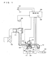
- Engine 100 is an internal combustion engine that allows a mixture of air aspirated through an air cleaner 102 and a fuel injected by an injector 104 to be ignited in a combustion chamber by an ignition plug 104 and thus combusted.
- the air fuel mixture combusted causes combustion pressure which presses a piston 108 down and a crank shaft 110 rotates.
- the combusted air fuel mixture (or exhaust gas) is purified by a ternary catalyst 112 and thereafter discharged outside the vehicle.
- Engine 110 aspirates an amount of air adjusted by a throttle valve 114.
- Engine 100 is controlled by an engine ECU 200 having connected thereto a knock sensor 300, a water temperature sensor 302, a crank position sensor 306 arranged opposite a timing rotor 304, a throttle opening sensor 308, a vehicle speed sensor 310, and an ignition switch 312.
- Knock sensor 300 is implemented by a piezoelectric element. As engine 100 vibrates, knock sensor 300 generates a voltage having a magnitude corresponding to that of the vibration. Knock sensor 300 transmits a signal representing the voltage to engine ECU 200. Water temperature sensor 302 detects temperature of refrigerant water in engine 100 at a water jacket and transmits a signal representing a resultant detection to engine ECU 200.
- Timing rotor 304 is provided at a crank shaft 110 and rotates as crank shaft 110 do. Timing rotor 304 is circumferentially provided with a plurality of protrusions spaced as predetermined. Crank position sensor 306 is arranged opposite the protrusions of timing rotor 304. When timing rotor 304 rotates, an air gap between the protrusions of timing rotor 304 and crank position sensor 306 varies, and a coil portion of crank position sensor 306 passes an increased/decreased magnetic flux and thus experiences electromotive force. Crank position sensor 306 transmits a signal representing the electromotive force to engine ECU 200. From the signal, engine ECU 200 detects a crank angle.
- Throttle opening sensor 308 detects a throttle opening and transmits a signal representing a resultant detection to engine ECU 200.
- Vehicle speed sensor 310 detects a rate of rotation of a wheel (not shown) and transmits a signal representing a resultant detection to engine ECU 200. From the wheel's rate of rotation engine ECU 200 calculates the vehicle's speed.
- Ignition switch 312 is turned on by a driver starting engine 100.
- Engine ECU 200 uses the signals transmitted from each sensor and ignition switch 312 and a map and program stored in a memory 202 to perform an arithmetic operation to control equipment so that engine 100 has a desired driving condition.
- engine ECU 200 depends on a signal transmitted from knock sensor 300 and a crank angle to detect a waveform of vibration of engine 100 at a predetermined knock detection gate (a section from a predetermined first crank angle to a predetermined second crank angle) (hereinafter the waveform will also simply be referred to as "vibration waveform”) and from the detected vibration waveform determines whether engine 100 knocks.
- a predetermined knock detection gate a section from a predetermined first crank angle to a predetermined second crank angle
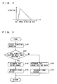
- the engine ECU 200 memory 202 stores a knock waveform model corresponding to a model of a waveform of vibration caused when engine 100 knocks, as shown in Fig. 2 .
- the model is stored in association with vibration of a plurality of frequency bands. More specifically, a plurality of such models are stored.
- the models are obtained as follows: an experiment or the like is conducted to cause engine 100 to knock to detect the engine's vibration waveform, from which the models are previously created and stored. It should be noted, however, that the models may be created by a different method.
- Engine ECU 200 compares a detected waveform with the stored models to determine whether engine 100 knocks.
- ignition control system engine ECU 200 executes a program controlled in a structure as will be described hereinafter.
- step (hereinafter simply referred to as "S") 100 engine ECU 200 detects the engine 100 vibration waveform based on a signal transmitted from knock sensor 300 and a crank angle.
- engine ECU 200 determines for all frequency bands whether any detected vibration waveform matches any stored knock waveform model within a predetermined range. In the present embodiment whether the detected vibration waveform and the model match within the predetermined range may be determined for example by whether for each crank angle the engine 100 vibrates with a deviation falling within a reference value or whether such deviations averaged fall within the reference value. Note that a method different than the above may alternatively be employed to determine whether the detected waveform and the stored model match within the predetermined range. If the detected waveform and the stored model match within the predetermined range (YES at S102) the control proceeds with S104. Otherwise (NO at S102) the control proceeds with S 108.
- engine ECU 200 determines that engine 100 knocks.
- engine ECU 200 introduces a spark retard.
- engine ECU 200 determines that engine 100 does not knock.
- engine ECU 200 introduces a spark advance.
- ignition control system engine ECU 200 operates as will be described hereinafter.
- knock sensor 300 When a driver turns on ignition switch 312 to start engine 100 and knock sensor 300 transmits a signal from which and a crank angle the engine 100 vibration waveform is detected (S100) and a decision is made as to whether the detected waveform matches a stored knock waveform model within the predetermined range (S102).
- a vibration waveform indicated by a chained, single dashed line and a knock waveform model indicated by a solid line match within the predetermined range (YES at S 102) the control determines that the engine knocks (S 104) and introduces a spark retard (S106) to prevent the engine from knocking.
- a vibration waveform indicated by a chained, double dashed line and the model indicated by the solid line do not match within the predetermined range (NO at S 102)
- the control determines that the engine does not knock even if the vibration waveform has a peak equal to or larger in value than that of vibration of the model (S 108).
- the control introduces a spark advance (S110).
- the engine ECU depends on a signal received from a knock sensor and a crank angle to detect the engine's vibration waveform at a predetermined knock detection gate and compares the vibration waveform with a knock waveform model to determine whether the engine knocks.
- a crank angle for which vibration occurs can also be depended on to determine whether the engine knocks. Consequently, whether engine knocks or not can be determined with high precision.
- FIG. 5-8 the present invention in a second embodiment will be described.
- the present embodiment is distinguished from the first embodiment by correcting a knock waveform model.
- the remainder in configuration and function is identical to the first embodiment.
- the present embodiment's ignition control system has engine ECU 200 executing a program controlled in a structure as will be described hereinafter. Note that engine ECU 200 executes the program described in the first embodiment and in addition thereto a program as will be described hereinafter.
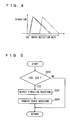
- engine ECU 200 determines whether injector 100 is interrupted from injecting a fuel (hereinafter also referred to as "the fuel is cut”). Whether the fuel is cut may be determined by whether the vehicle is in a driving condition cutting the fuel (e.g., whether the accelerator is turned off and the engine rotates at at least a predetermined rate). If the fuel is cut (YES at S200) the control proceeds with S202, otherwise (NO at S202) this process ends.
- a driving condition cutting the fuel e.g., whether the accelerator is turned off and the engine rotates at at least a predetermined rate.
- engine ECU 200 detects the engine 100 vibration waveform from a signal transmitted from knock sensor 300 and a crank angle. At S204 engine ECU 200 depends on the detected vibration waveform to correct a knock waveform model stored in memory 202.
- ignition control system engine ECU 200 operates as will be described hereinafter.
- the engine 100 vibration waveform is detected (S202).
- the detected waveform will be a waveform of mechanical vibration of engine 100 itself, as shown in Fig. 6 .
- the model has the waveform of the mechanical vibration of engine 100 itself added thereto to correct the model, as shown in Fig. 8 (S204).
- the model can be more approximate to a waveform of vibration of engine 100 caused when the engine knocks.
- the engine ECU corrects a knock waveform model in a memory by mechanical vibration of the engine itself detected when the fuel is cut.
- the model can be approximated to the engine's vibration waveform caused when the engine knocks, and whether the engine knocks or not can thus be determined with high precision.
- the present invention in a third embodiment will be described.
- the present embodiment is distinguished from the first embodiment by correcting a knock waveform model.
- the remainder in configuration and function is identical to the first embodiment.
- the present embodiment's ignition control system has engine ECU 200 executing a program controlled in a structure as will be described hereinafter. Note that engine ECU 200 executes the program described in the first embodiment and in addition thereto a program as will be described hereinafter.
- engine ECU 200 determines whether the engine 100 provides an output that transitions (or varies). Whether the engine 100 output is in transition may be determined for example by whether a throttle opening's variation rate, aspirated air's temperature, the engine 100 refrigerant water's temperature and the like are larger in value than predetermined. If the engine 100 output is in transition (YES at S300), the control proceeds with S302. Otherwise (NO at S300) this process ends.
- engine ECU 200 detects the engine 100 vibration waveform from a signal received from knock sensor 300.
- engine ECU 200 determines whether the detected vibration waveform does not contain a vibration component attributed to knocking. This decision may be made for example by whether the vibration waveform has a peak having a value smaller than a predetermined value. If the detected vibration waveform does not contain a vibration component attributed to knocking (YES at S304), the control proceeds with S306. Otherwise (NO at S304) this process ends.
- engine ECU 200 corrects a knock waveform model in memory 202, as based on the detected vibration waveform.
- ignition control system engine ECU 200 operates as will be described hereinafter.
- the engine 100 vibration waveform is detected (S302). If the engine 100 output is in transition (YES at S300) the engine 100 vibration waveform is detected (S302). If the engine 100 output is in transition, the engine tends to knock, and it is necessary to determine with high precision whether the engine has knocked. When the engine's output is in transition, however, the engine 100 vibration varies even if the engine does not knock. As such, if the Fig. 10 knock waveform model is fixed, and engine 100 knocks, the engine 100 itselfs mechanical vibration affects so that the model and a detected vibration waveform do not match, which may result in an erroneous decision that the engine does not knock.
- a detected vibration waveform does not contain a vibration component attributed to knocking (YES at S304)
- the vibration waveform is added to a knock waveform model stored in memory 202 to correct the model, as shown in Fig. 12 (S306). This allows the model stored in memory 202 to match by the engine 100 vibration waveform caused when the engine knocks.
- the engine ECU corrects a knock waveform model stored in a memory by a vibration waveform detected when the engine's output is in transition.
- the model can be more approximate to a vibration waveform caused when the engine knocks, and whether the engine knocks or not can be determined with high precision.
- ignition control system engine ECU 200 executes a program controlled in a structure as will be described hereinafter.
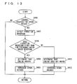
- engine ECU 200 determines whether engine 100 is controlled to have a spark retard from a predetermined crank angle (formed for example when engine 100 starts) (hereinafter such control will also be referred to as "spark retard control"). Whether spark retard control is effected may be determined from whether the vehicle is in a condition subject to spark retard, such as whether the catalyst's temperature is lower than a predetermined temperature, whether the vehicle is rapidly accelerated, or the like. If spark retard control is effected (YES at S400), the control proceeds with S402, otherwise (NO at S400) this process ends.
- engine ECU 200 detects the engine 100 vibration waveform based on a signal transmitted from knock sensor 300.
- engine ECU 200 determines whether a detected vibration waveform that is equal to or higher than a predetermined frequency matches a knock waveform model stored in memory 202 within a predetermined range. More specifically, whether the engine knocks is not determined for waveforms of vibration of low frequency. If the model and the detected vibration waveform match within the predetermined range (YES at S404) the control proceeds with S406, otherwise (NO at S404) the control proceeds with S410.
- engine ECU 200 determines that engine 100 knocks. At S408 engine ECU 200 introduces a spark retard. At S410 engine ECU 200 determines that engine 100 does not knock. At S412 engine ECU 200 introduces a spark advance.
- ignition control system engine ECU 200 operates as will be described hereinafter.
- spark retard control When spark retard control is effected (YES at S400), the engine 100 vibration waveform is detected (S402).
- spark retard control there exists a crank angle range for which a waveform of vibration of low frequency is analogous to a waveform provided when the engine knocks despite that the engine does not knock (hereinafter this range will be referred to as a pseudo knock range).
- this range will be referred to as a pseudo knock range.
- a decision is made as to whether a detected vibration waveform that is equal to or higher than a predetermined frequency matches a knock waveform model stored in memory 202 within a predetermined range (S404).
- the engine ECU determines whether a detected vibration waveform that is equal to or higher than a predetermined frequency matches a knock waveform model stored in a memory within a predetermined range. If so, a decision is made that the engine knocks. Otherwise, a decision is made that the engine does not knock. This can prevent an erroneous decision associated with a pseudo knock range for which a waveform of vibration of low frequency is analogous to a waveform provided when the engine knocks.
- the present invention differs from the first embodiment in that waveforms of vibration of different frequency bands are composited together to detect a vibration waveform. Furthermore a nock waveform model provides vibration having a magnitude that does not uniquely correspond to a crank angle. The remainder in configuration and hence function is identical to the first embodiment.
- the engine ECU 200 memory 202 has stored therein a knock waveform model corresponding to a portion of vibration, represented in magnitude, caused by knocking that follows a peak. Note that a knock waveform model that corresponds to vibration attributed to knocking following the rise of the vibration, may be stored.
- vibration's magnitude is represented by a dimensionless number of 0 to 1 and does not uniquely correspond to a crank angle. More specifically, for the present embodiment's knock waveform model, after vibration's peak value in magnitude the vibration is reduced in magnitude as the crank angle increases, however the crank angle for which the vibration has the peak value in magnitude is not determined. Furthermore, the model is a wave of a composition of vibration of frequency bands. In Fig. 14 , CA represents a crank angle.
- ignition control system engine ECU 200 executes a program controlled in a structure as will be described hereinafter.
- engine ECU 200 detects the engine 100 vibration in magnitude from a signal transmitted from knock sensor 300.
- the vibration's magnitude is represented by a value of voltage output from knock sensor 300.
- the vibration's magnitude may be represented by a value corresponding to the value of the voltage output from knock sensor 300.
- the vibration's magnitude is detected in a combustion process for an angle from a top dead center to (a crank angle of) 90°.
- engine ECU 200 calculates for a crank angle of every five degrees an integration (hereinafter also be referred to as an "integrated value") of values of voltage output from knock sensor 300 (i.e., representing magnitude of vibration).
- the integrated value is calculated for vibration of each frequency band.
- a waveform of vibration of each frequency band is detected.
- the integrated value may be calculated for a crank angle other than every five degrees.
- engine ECU 200 composites waveforms of vibration of frequency bands. Thus engine 100 vibration waveform is detected.
- engine ECU 200 uses the largest integrated value of waveforms of vibration composited to normalize the engine's vibration waveform.
- normalizing a waveform means dividing each integrated value by the largest integrated value to represent the vibration's magnitude by a dimensionless number of 0 to 1.
- engine ECU 200 calculates a coefficient of correlation K, a value associated with a deviation of a normalized vibration waveform and a knock waveform model.
- a timing of the normalized vibration waveform achieving vibration maximized in magnitude and that of the model achieving vibration maximized in magnitude are matched, while the deviation in absolute value (or an amount of offset) of the normalized vibration waveform and the model is calculated for each crank angle (of five degrees) to calculate the coefficient of correlation K.
- coefficient of correlation K may be calculated by a different method.
- engine ECU 200 determines whether knock intensity N is larger than a predetermined reference value. If so (YES at S512) the control proceeds with S514, otherwise (NO at S512) the control proceeds with S518.
- engine ECU 200 determines that engine 100 knocks. At S516 engine ECU 200 introduces a spark retard. At S518 engine ECU 200 determines that engine 100 does not knock. At S502 engine ECU 200 introduces a spark advance.
- ignition control system engine ECU 200 operates as will be described hereinafter.
- each integrated value for every five degrees is calculated for each frequency (S502) and integrated values calculated for the frequencies are composited together (S504).
- S502 the engine 100 vibration waveform is detected.
- Fig. 16 represents a vibration waveform in a rectangle
- each integrated value may be connected by a line to represent the vibration waveform.
- each integrated value alone may be represented in a dot to represent the vibration waveform.
- Using an integrated value for every five degrees to detect a vibration waveform allows minimized detection of a waveform of vibration having a complicated form attributed to vibration having a magnitude varying minutely. This can help to compare a detected vibration waveform with a knock waveform model.
- the maximum integrated value is used to normalize the engine's vibration waveform (S506).
- the integrated value for 15° to 20° is used to normalize the engine's vibration waveform for the sake of illustration.
- a timing of a normalized vibration waveform providing vibration maximized in magnitude and that of a knock waveform model providing vibration maximized in magnitude are matched, while a deviation in absolute value ⁇ S (I) of the normalized vibration waveform and the knock waveform model is calculated for each crank angle.
- vibration's magnitude can also be depended on to analyze in more detail whether the engine 100 vibration is attributed to knocking.
- knock intensity N is larger than a predetermined reference value (YES at S512) a decision is made that engine knocks (S514) and a spark retard is introduced (S516) to prevent the engine from knocking.
- knock intensity N is not larger than the predetermined reference value (NO at S512)
- the engine ECU detects the engine's vibration waveform based on a signal transmitted from a knock sensor and compares the vibration waveform with a knock vibration model to calculate the coefficient of correlation K. Furthermore, the product of the coefficient of correlation K and the vibration waveform's maximum integrated value P is divided by the BGL to calculate knock intensity N. If knock intensity N is larger than a reference value, a decision is made that the engine knocks. If knock intensity N is not larger than the reference value, a decision is made that the engine does not knock.
- vibration's magnitude can also be depended on to analyze in more detail whether the engine's vibration is attributed to knocking. Thus whether the engine knocks or not can be determined with high precision.
- An engine ECU executes a program including the steps of: detecting a waveform of vibration of an engine at a predetermined knock detection gate (S100); determining whether a detected vibration's waveform and a knock waveform model stored in memory match within a predetermined range; if the model and the detected vibration's waveform match within the predetermined range (YES at S102), determining that the engine knocks (S104); and if the model and the detected vibration's waveform do not match within the predetermined range (NO at S102), then determining that the engine does not knock (S 108).
- S100 predetermined knock detection gate
Applications Claiming Priority (3)
| Application Number | Priority Date | Filing Date | Title |
|---|---|---|---|
| JP2004127025 | 2004-04-22 | ||
| JP2004371489A JP4410674B2 (ja) | 2004-04-22 | 2004-12-22 | 内燃機関のノッキング判定装置およびその装置を含む点火制御システム |
| EP05737093.4A EP1738148B1 (fr) | 2004-04-22 | 2005-04-21 | Dispositif de determination de cliquetis dans un moteur a combustion interne et systeme de commande d'allumage comportant un tel dispositif |
Related Parent Applications (2)
| Application Number | Title | Priority Date | Filing Date |
|---|---|---|---|
| EP05737093.4A Division EP1738148B1 (fr) | 2004-04-22 | 2005-04-21 | Dispositif de determination de cliquetis dans un moteur a combustion interne et systeme de commande d'allumage comportant un tel dispositif |
| EP05737093.4A Division-Into EP1738148B1 (fr) | 2004-04-22 | 2005-04-21 | Dispositif de determination de cliquetis dans un moteur a combustion interne et systeme de commande d'allumage comportant un tel dispositif |
Publications (1)
| Publication Number | Publication Date |
|---|---|
| EP2108935A1 true EP2108935A1 (fr) | 2009-10-14 |
Family
ID=34966342
Family Applications (2)
| Application Number | Title | Priority Date | Filing Date |
|---|---|---|---|
| EP09167082A Withdrawn EP2108935A1 (fr) | 2004-04-22 | 2005-04-21 | Dispositif de détermination de cliquetis de moteur à combustion interne et système de commande d'ignition le comportant |
| EP05737093.4A Active EP1738148B1 (fr) | 2004-04-22 | 2005-04-21 | Dispositif de determination de cliquetis dans un moteur a combustion interne et systeme de commande d'allumage comportant un tel dispositif |
Family Applications After (1)
| Application Number | Title | Priority Date | Filing Date |
|---|---|---|---|
| EP05737093.4A Active EP1738148B1 (fr) | 2004-04-22 | 2005-04-21 | Dispositif de determination de cliquetis dans un moteur a combustion interne et systeme de commande d'allumage comportant un tel dispositif |
Country Status (4)
| Country | Link |
|---|---|
| US (1) | US7263430B2 (fr) |
| EP (2) | EP2108935A1 (fr) |
| JP (1) | JP4410674B2 (fr) |
| WO (1) | WO2005103466A2 (fr) |
Cited By (2)
| Publication number | Priority date | Publication date | Assignee | Title |
|---|---|---|---|---|
| US9279406B2 (en) | 2012-06-22 | 2016-03-08 | Illinois Tool Works, Inc. | System and method for analyzing carbon build up in an engine |
| EP1875187B1 (fr) * | 2005-04-26 | 2016-05-11 | Toyota Jidosha Kabushiki Kaisha | Detecteur de cliquetis dans un moteur a combustion interne |
Families Citing this family (26)
| Publication number | Priority date | Publication date | Assignee | Title |
|---|---|---|---|---|
| JP2006300036A (ja) * | 2005-04-25 | 2006-11-02 | Toyota Motor Corp | 内燃機関のノッキング判定装置 |
| JP4404811B2 (ja) * | 2005-06-28 | 2010-01-27 | トヨタ自動車株式会社 | ノッキング状態判定装置 |
| JP4452660B2 (ja) * | 2005-06-28 | 2010-04-21 | トヨタ自動車株式会社 | ノッキング状態判定装置 |
| JP4468865B2 (ja) | 2005-06-30 | 2010-05-26 | トヨタ自動車株式会社 | 内燃機関のノッキング判定装置 |
| JP4404813B2 (ja) | 2005-06-30 | 2010-01-27 | トヨタ自動車株式会社 | 内燃機関のノッキング判定装置 |
| JP4756968B2 (ja) * | 2005-09-16 | 2011-08-24 | 株式会社デンソー | 内燃機関のノック判定装置 |
| JP4589238B2 (ja) * | 2006-01-10 | 2010-12-01 | トヨタ自動車株式会社 | 内燃機関のノッキング判定装置 |
| JP2007211690A (ja) * | 2006-02-09 | 2007-08-23 | Toyota Motor Corp | 内燃機関の点火時期制御装置 |
| JP4358198B2 (ja) | 2006-03-20 | 2009-11-04 | トヨタ自動車株式会社 | 内燃機関のノッキング判定装置 |
| JP4575902B2 (ja) * | 2006-05-29 | 2010-11-04 | トヨタ自動車株式会社 | 内燃機関のノッキング判定装置 |
| JP4447576B2 (ja) * | 2006-05-29 | 2010-04-07 | トヨタ自動車株式会社 | 内燃機関のノッキング判定装置 |
| JP4357501B2 (ja) * | 2006-05-29 | 2009-11-04 | トヨタ自動車株式会社 | 内燃機関のノッキング判定装置 |
| JP4390786B2 (ja) | 2006-06-06 | 2009-12-24 | トヨタ自動車株式会社 | 内燃機関のノッキング判定装置 |
| JP4221013B2 (ja) | 2006-06-16 | 2009-02-12 | トヨタ自動車株式会社 | 内燃機関の点火時期制御装置 |
| JP4312213B2 (ja) | 2006-06-28 | 2009-08-12 | トヨタ自動車株式会社 | 内燃機関のノッキング判定装置 |
| JP4597167B2 (ja) | 2006-06-28 | 2010-12-15 | トヨタ自動車株式会社 | 内燃機関のノッキング判定装置 |
| JP4490455B2 (ja) * | 2006-10-06 | 2010-06-23 | トヨタ自動車株式会社 | 内燃機関のノッキング判定装置、ノッキング判定方法、その方法を実現するプログラムおよびそのプログラムを記録した記録媒体 |
| JP4919020B2 (ja) * | 2006-10-12 | 2012-04-18 | トヨタ自動車株式会社 | 内燃機関のノック判定装置 |
| JP2008095602A (ja) * | 2006-10-12 | 2008-04-24 | Denso Corp | 内燃機関のノック判定装置 |
| JP4729536B2 (ja) * | 2007-05-29 | 2011-07-20 | トヨタ自動車株式会社 | 内燃機関のノッキング判定装置、判定方法およびその方法をコンピュータで実現されるプログラムならびにそのプログラムを記録した記録媒体 |
| JP4600431B2 (ja) * | 2007-05-30 | 2010-12-15 | トヨタ自動車株式会社 | 内燃機関のノッキング判定装置 |
| KR101316224B1 (ko) * | 2007-12-17 | 2013-10-08 | 현대자동차주식회사 | 엔진 점화시기 효율 제어방법 |
| JP5253432B2 (ja) * | 2010-02-16 | 2013-07-31 | トヨタ自動車株式会社 | 内燃機関のノッキング判定装置 |
| KR101393879B1 (ko) * | 2011-10-17 | 2014-05-13 | 현대자동차주식회사 | 엔진의 점화시기 제어 방법 |
| WO2013065400A1 (fr) * | 2011-11-01 | 2013-05-10 | 日産自動車株式会社 | Dispositif de diagnostic de dysfonctionnement et procédé de diagnostic de dysfonctionnement pour capteur de cliquetis |
| JP5839972B2 (ja) * | 2011-12-12 | 2016-01-06 | 三菱電機株式会社 | 内燃機関の制御装置 |
Citations (4)
| Publication number | Priority date | Publication date | Assignee | Title |
|---|---|---|---|---|
| US4565087A (en) | 1983-05-28 | 1986-01-21 | Robert Bosch Gmbh | Method and apparatus for recognition of knocking in an internal combustion engine |
| GB2245382A (en) | 1990-04-28 | 1992-01-02 | Motorola Inc | Automotive diagnostic system |
| US5386722A (en) | 1993-03-24 | 1995-02-07 | Ford Motor Company | Method and apparatus for statistically determining knock borderline and evaluating knock intensity in an internal combustion engine |
| US20020014108A1 (en) | 2000-07-05 | 2002-02-07 | Peter Hohner | Method for detecting knocking combustion in the operation of an internal combustion engine |
Family Cites Families (24)
| Publication number | Priority date | Publication date | Assignee | Title |
|---|---|---|---|---|
| JPS6125951A (ja) * | 1984-07-17 | 1986-02-05 | Kyushu Denki Seizo Kk | 着火時振動の包絡線波形の統計的特徴を利用するエンジンの異常診断方式 |
| JPS631761A (ja) | 1986-06-19 | 1988-01-06 | Nissan Motor Co Ltd | 内燃機関の点火時期制御装置 |
| US5083278A (en) * | 1989-04-14 | 1992-01-21 | Fuji Jukogyo Kabushiki Kaisha | Knocking detection device for an automotive engine |
| JP2948828B2 (ja) * | 1989-04-14 | 1999-09-13 | 富士重工業株式会社 | エンジンのノック検出装置 |
| JP2922027B2 (ja) * | 1991-08-01 | 1999-07-19 | 株式会社日立製作所 | 内燃機関の燃焼状態検出装置 |
| JP3325067B2 (ja) | 1993-02-26 | 2002-09-17 | 株式会社日立製作所 | 内燃機関のノッキング検出装置 |
| US5421195A (en) * | 1993-07-01 | 1995-06-06 | Wlodarczyk; Marek T. | Fiber optic microbend sensor for engine knock and misfire detection |
| JP3790932B2 (ja) * | 1995-05-25 | 2006-06-28 | 株式会社キューキ | 内燃機関の動作状態判定装置 |
| FR2765623B1 (fr) | 1997-07-03 | 1999-09-10 | Renault | Dispositif de detection et de mesure de cliquetis et systeme anticliquetis comprenant un tel dispositif |
| JP2000205096A (ja) | 1999-01-19 | 2000-07-25 | Toyota Motor Corp | 内燃機関のノック検出装置 |
| JP4390939B2 (ja) | 1999-12-16 | 2009-12-24 | 株式会社デンソー | 内燃機関用ノック制御装置 |
| JP3753583B2 (ja) * | 2000-02-15 | 2006-03-08 | 株式会社デンソー | 内燃機関用ノック制御装置 |
| JP4465928B2 (ja) * | 2001-07-04 | 2010-05-26 | 株式会社デンソー | 内燃機関のノック制御装置 |
| JP2002357156A (ja) | 2001-05-30 | 2002-12-13 | Mitsubishi Electric Corp | 内燃機関用ノック制御装置 |
| JP2003172196A (ja) | 2001-12-06 | 2003-06-20 | Toyota Motor Corp | 内燃機関のノック制御装置 |
| JP2003278592A (ja) | 2002-03-22 | 2003-10-02 | Toyota Motor Corp | 内燃機関のノック制御装置 |
| JP4211296B2 (ja) * | 2002-06-12 | 2009-01-21 | 日産自動車株式会社 | 内燃機関のノック制御装置 |
| JP3851612B2 (ja) * | 2003-02-10 | 2006-11-29 | 本田技研工業株式会社 | 内燃機関のノック制御装置 |
| JP4297734B2 (ja) * | 2003-05-28 | 2009-07-15 | 株式会社デンソー | 内燃機関のノック制御装置 |
| US6968825B2 (en) * | 2003-06-06 | 2005-11-29 | Mazda Motor Corporation | Control device for spark-ignition engine |
| JP4165751B2 (ja) | 2003-07-03 | 2008-10-15 | 株式会社デンソー | 内燃機関のノック検出装置 |
| JP4311657B2 (ja) * | 2004-04-15 | 2009-08-12 | 株式会社デンソー | 内燃機関のノック検出装置 |
| JP4375728B2 (ja) * | 2004-04-15 | 2009-12-02 | 株式会社デンソー | 内燃機関の制御装置 |
| JP4390104B2 (ja) * | 2004-04-16 | 2009-12-24 | 株式会社デンソー | 内燃機関のノック判定装置 |
-
2004
- 2004-12-22 JP JP2004371489A patent/JP4410674B2/ja active Active
-
2005
- 2005-04-19 US US11/108,809 patent/US7263430B2/en active Active
- 2005-04-21 WO PCT/JP2005/008108 patent/WO2005103466A2/fr active Application Filing
- 2005-04-21 EP EP09167082A patent/EP2108935A1/fr not_active Withdrawn
- 2005-04-21 EP EP05737093.4A patent/EP1738148B1/fr active Active
Patent Citations (4)
| Publication number | Priority date | Publication date | Assignee | Title |
|---|---|---|---|---|
| US4565087A (en) | 1983-05-28 | 1986-01-21 | Robert Bosch Gmbh | Method and apparatus for recognition of knocking in an internal combustion engine |
| GB2245382A (en) | 1990-04-28 | 1992-01-02 | Motorola Inc | Automotive diagnostic system |
| US5386722A (en) | 1993-03-24 | 1995-02-07 | Ford Motor Company | Method and apparatus for statistically determining knock borderline and evaluating knock intensity in an internal combustion engine |
| US20020014108A1 (en) | 2000-07-05 | 2002-02-07 | Peter Hohner | Method for detecting knocking combustion in the operation of an internal combustion engine |
Cited By (2)
| Publication number | Priority date | Publication date | Assignee | Title |
|---|---|---|---|---|
| EP1875187B1 (fr) * | 2005-04-26 | 2016-05-11 | Toyota Jidosha Kabushiki Kaisha | Detecteur de cliquetis dans un moteur a combustion interne |
| US9279406B2 (en) | 2012-06-22 | 2016-03-08 | Illinois Tool Works, Inc. | System and method for analyzing carbon build up in an engine |
Also Published As
| Publication number | Publication date |
|---|---|
| US20050251320A1 (en) | 2005-11-10 |
| JP2005330954A (ja) | 2005-12-02 |
| WO2005103466A3 (fr) | 2006-03-09 |
| US7263430B2 (en) | 2007-08-28 |
| EP1738148B1 (fr) | 2016-10-12 |
| WO2005103466A2 (fr) | 2005-11-03 |
| EP1738148A2 (fr) | 2007-01-03 |
| JP4410674B2 (ja) | 2010-02-03 |
Similar Documents
| Publication | Publication Date | Title |
|---|---|---|
| EP2108935A1 (fr) | Dispositif de détermination de cliquetis de moteur à combustion interne et système de commande d'ignition le comportant | |
| US7251556B2 (en) | Knock determination device for internal combustion engine | |
| US7669459B2 (en) | Knocking determination device for internal combustion engine | |
| US7945379B2 (en) | Knock determination device and method for internal combustion engine | |
| EP1896816B1 (fr) | Dispositif de determination d'un etat de cognement | |
| US7206691B2 (en) | Internal combustion engine knock determination device | |
| US7478624B2 (en) | Ignition timing control device of internal combustion engine | |
| US20060185422A1 (en) | Knock determination device for internal combustion engine | |
| KR100929994B1 (ko) | 내연기관의 노킹 판정 장치 및 방법 | |
| US7478622B2 (en) | Device and method for determining knocking of internal combustion engine | |
| US20060236753A1 (en) | Internal combustion engine knock determination device | |
| US7621172B2 (en) | Knocking determination device for internal combustion engine | |
| US20090005956A1 (en) | Knocking Determination Device and Knocking Determination Method of Internal Combustion Engine | |
| CN100520331C (zh) | 内燃机爆震判定装置和包含该装置的点火控制系统 | |
| JP2006307711A (ja) | 内燃機関のノッキング判定装置 | |
| JP4410719B2 (ja) | 内燃機関のノッキング判定装置 |
Legal Events
| Date | Code | Title | Description |
|---|---|---|---|
| PUAI | Public reference made under article 153(3) epc to a published international application that has entered the european phase |
Free format text: ORIGINAL CODE: 0009012 |
|
| 17P | Request for examination filed |
Effective date: 20090803 |
|
| AC | Divisional application: reference to earlier application |
Ref document number: 1738148 Country of ref document: EP Kind code of ref document: P |
|
| AK | Designated contracting states |
Kind code of ref document: A1 Designated state(s): DE FR IT |
|
| RAP1 | Party data changed (applicant data changed or rights of an application transferred) |
Owner name: DENSO CORPORATION Owner name: TOYOTA JIDOSHA KABUSHIKI KAISHA |
|
| 17Q | First examination report despatched |
Effective date: 20100128 |
|
| R17C | First examination report despatched (corrected) |
Effective date: 20100226 |
|
| STAA | Information on the status of an ep patent application or granted ep patent |
Free format text: STATUS: THE APPLICATION IS DEEMED TO BE WITHDRAWN |
|
| 18D | Application deemed to be withdrawn |
Effective date: 20100909 |