EP2106519B1 - Vorrichtung und verfahren zur durchführung chemischer und/oder physikalischer reaktionen zwischen einem feststoff und einem gas sowie anlage zur zementherstellung - Google Patents
Vorrichtung und verfahren zur durchführung chemischer und/oder physikalischer reaktionen zwischen einem feststoff und einem gas sowie anlage zur zementherstellung Download PDFInfo
- Publication number
- EP2106519B1 EP2106519B1 EP08774293A EP08774293A EP2106519B1 EP 2106519 B1 EP2106519 B1 EP 2106519B1 EP 08774293 A EP08774293 A EP 08774293A EP 08774293 A EP08774293 A EP 08774293A EP 2106519 B1 EP2106519 B1 EP 2106519B1
- Authority
- EP
- European Patent Office
- Prior art keywords
- gas
- conduit
- helical
- solid material
- spiral
- Prior art date
- Legal status (The legal status is an assumption and is not a legal conclusion. Google has not performed a legal analysis and makes no representation as to the accuracy of the status listed.)
- Not-in-force
Links
- 238000006243 chemical reaction Methods 0.000 title claims abstract description 7
- 239000000126 substance Substances 0.000 title claims abstract description 7
- 239000011343 solid material Substances 0.000 title claims abstract 21
- 239000004568 cement Substances 0.000 title claims description 6
- 238000000034 method Methods 0.000 title description 3
- 238000000926 separation method Methods 0.000 claims abstract description 26
- 239000000725 suspension Substances 0.000 claims abstract description 22
- 239000000463 material Substances 0.000 claims abstract description 13
- 238000007599 discharging Methods 0.000 claims abstract description 12
- 238000001354 calcination Methods 0.000 claims abstract description 6
- 238000001816 cooling Methods 0.000 claims abstract description 6
- 238000004519 manufacturing process Methods 0.000 claims description 4
- 230000001174 ascending effect Effects 0.000 claims description 3
- 239000007789 gas Substances 0.000 description 64
- 239000007787 solid Substances 0.000 description 32
- 230000008021 deposition Effects 0.000 description 9
- 239000002245 particle Substances 0.000 description 4
- 238000002474 experimental method Methods 0.000 description 2
- 238000010438 heat treatment Methods 0.000 description 2
- 230000015572 biosynthetic process Effects 0.000 description 1
- 238000004891 communication Methods 0.000 description 1
- 238000010276 construction Methods 0.000 description 1
- 230000001419 dependent effect Effects 0.000 description 1
- 239000000203 mixture Substances 0.000 description 1
- JTJMJGYZQZDUJJ-UHFFFAOYSA-N phencyclidine Chemical class C1CCCCN1C1(C=2C=CC=CC=2)CCCCC1 JTJMJGYZQZDUJJ-UHFFFAOYSA-N 0.000 description 1
- 239000002994 raw material Substances 0.000 description 1
Images

Classifications
-
- F—MECHANICAL ENGINEERING; LIGHTING; HEATING; WEAPONS; BLASTING
- F27—FURNACES; KILNS; OVENS; RETORTS
- F27B—FURNACES, KILNS, OVENS OR RETORTS IN GENERAL; OPEN SINTERING OR LIKE APPARATUS
- F27B7/00—Rotary-drum furnaces, i.e. horizontal or slightly inclined
- F27B7/20—Details, accessories or equipment specially adapted for rotary-drum furnaces
- F27B7/2016—Arrangements of preheating devices for the charge
- F27B7/2025—Arrangements of preheating devices for the charge consisting of a single string of cyclones
-
- B—PERFORMING OPERATIONS; TRANSPORTING
- B01—PHYSICAL OR CHEMICAL PROCESSES OR APPARATUS IN GENERAL
- B01D—SEPARATION
- B01D45/00—Separating dispersed particles from gases or vapours by gravity, inertia, or centrifugal forces
- B01D45/12—Separating dispersed particles from gases or vapours by gravity, inertia, or centrifugal forces by centrifugal forces
- B01D45/16—Separating dispersed particles from gases or vapours by gravity, inertia, or centrifugal forces by centrifugal forces generated by the winding course of the gas stream, the centrifugal forces being generated solely or partly by mechanical means, e.g. fixed swirl vanes
-
- C—CHEMISTRY; METALLURGY
- C04—CEMENTS; CONCRETE; ARTIFICIAL STONE; CERAMICS; REFRACTORIES
- C04B—LIME, MAGNESIA; SLAG; CEMENTS; COMPOSITIONS THEREOF, e.g. MORTARS, CONCRETE OR LIKE BUILDING MATERIALS; ARTIFICIAL STONE; CERAMICS; REFRACTORIES; TREATMENT OF NATURAL STONE
- C04B7/00—Hydraulic cements
- C04B7/36—Manufacture of hydraulic cements in general
- C04B7/43—Heat treatment, e.g. precalcining, burning, melting; Cooling
Definitions
- the invention relates to a device and a method for carrying out chemical and / or physical reactions between a solid and a gas, in particular for preheating, cooling and / or calcination of fine-grained materials and a plant for cement production.
- the helical and / or spiral line has a rectangular cross section and is connected to a side surface of a cuboid deposition chamber.
- the connection point extends over the entire side surface of the cuboid deposition chamber.
- the lower part of the separation chamber tapers in a funnel shape and serves to discharge the solid while the gas is discharged upwards.
- the degree of separation of this deposition chamber is insufficient.
- a cyclotron for the separation of particles from a gas-particle mixture which has a sloping inlet opening. The particles are discharged downwards, while the gas is discharged via a dip tube opening into the cyclotron.
- the invention has the object to improve the degree of separation in the deposition chamber.
- the device according to the invention for carrying out chemical and / or physical reactions between a solid and a gas, in particular for preheating, cooling and / or calcining fine-grained materials consists essentially of at least one helical and / or spiral line in which a gas is generated by centrifugal forces Solids suspension and a gas stream are separated, and at least one associated with the end of the helical or spiral-like line separation area to which a solid line for discharging the solids flow and a gas line for discharging the gas stream is connected.
- the separation region is formed by a lower part of the gas line, wherein the separation region in the region of the junction of the helical and / or spiral-like line and the above subsequent part of the gas line the have the same diameter.
- the helical and / or spiral line opens tangentially to form a swirl flow, with an angle to the horizontal of at least 30 ° in the deposition area.
- a line is understood, which is at least partially helical and / or helical.
- the rotation of the helical and / or spiral-like line can in particular only extend over a smaller angular range, for example 90 °.
- the gas-solid suspension is introduced via the helical and / or spiral line into the gas line such that a swirl flow is generated in the gas line and the solid is discharged directly downwards.
- the helical and / or spiral line opens tangentially into the following gas line for generating the swirl flow.
- tangential of course, such connections of the helical and / or spiral line are meant, which are aligned approximately tangentially.
- the gas line is designed to be round in order to support the swirl flow. Furthermore, it is advantageous if the helical and / or spiral line is connected to the gas line at an angle to the horizontal, which is between 30-60 °. In this way, the solid is led directly down to the solid line, while the gas stream can be discharged upwards.
- the width of the helical line in the region of the connection to the deposition chamber is smaller than the width of the deposition chamber and preferably less than 50% of the width of the deposition chamber, viewed in the horizontal direction.
- the lower part of the gas line is funnel-shaped tapered, wherein the solid line is connected to the funnel-shaped tapered part of the gas line.
- the gas line may have a smaller or a larger diameter in the further course in the flow direction of the gas. In this way, procedural parameters such as pressure loss or separation efficiency can be influenced and optimized.
- the device is expediently designed as a multi-stage and / or multi-strand arrangement with a plurality of helical and / or spiral-type lines and associated gas lines.
- a gas in particular a gas.
- Solid suspension line can be provided, which has a riser and a Descending helical and / or spiral-like line, which are connected to one another via a deflection.
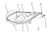
- the in the Fig. 1 to Fig. 3 apparatus for carrying out chemical and / or physical reactions between a solid 4 and a gas 5, in particular for preheating, cooling and / or calcining of fine-grained materials consists essentially of at least one helical and / or spiral line 1, at least one with the end of the helical and / or spiral-like line in communication gas line 2 for discharging the gas stream and a connected to the gas line solid line 3 for discharging the solid.
- the helical and / or spiral line 1 opens tangentially and at an angle ⁇ relative to the horizontal of at least 30 ° into the separation region 2a.
- the angle ⁇ is preferably in the range between 30 ° and 60 °.
- the gas line 2 or the separation region 2 a of the gas line 2 also has in its lower region a funnel-shaped tapering part 2 b, to which the solid line 3 is connected.
- the funnel-shaped tapered part 2b adjoins immediately below the junction of the helical and / or spiral line 1 at. It is within the scope of the invention, however, also conceivable that between the lower part of the junction of the helical and / or spiral line 1 and the funnel-shaped tapered part 2b, a small distance is provided, but less than the radius preferably less than half Radius, the gas line should be 2 in the area of the junction.
- the gas-solid suspension is fed via the helical and / or spiral line 1 to the gas line 2.
- the gas line 2 due to the centrifugal forces, a pre-separation of the gas-solid suspension into the solids stream 4 and the gas stream 5 occurs.
- the solid stream 4 previously separated from the gas stream is fed directly to the solid line 3 via the funnel-shaped tapering part 2b.
- the gas stream 5 is also transferred into a swirl flow and discharged upwards via the gas line 2. This prevents material from being re-absorbed and discharged by the gas stream.
- the obliquely downwardly directed material supply into the gas line also prevents the overlapping of the material flow with the swirl flow formed in the gas line occurring in the region of the mouth of the helical and / or spiral line 1.
- separation of the solids stream and the gas stream can be effected with high efficiency by generating this swirl flow.
- the cross section of the gas line 2 in the region of the junction 0.5 bits 1.5 times as large as the cross section of the helical and / or spiral line 1. This cross-sectional ratio supports the formation of the swirl flow.
- a gas-solid suspension line can be provided which has a riser 6 and the descending helical and / or spiral line 1, and Further, a deflection head 7 is provided which the riser. 6 with the helical and / or spiral line 1 connects. Due to the ascending and descending branch of the gas-solid suspension line, a sufficient contact time between gas and solid is ensured. On the other hand, a very compact design with comparatively low height can be achieved by this construction.
- the radius and / or the slope and / or the cross-sectional shape and / or the cross-sectional size of the helical and / or spiral line 1 changes in the flow direction of the gas-solid suspension.
- the helical and / or spiral line 1 can be adapted to external conditions. This is particularly advantageous when several stages are interleaved and arranged one above the other.
- the radius, pitch, cross-sectional shape and / or cross-sectional size can change continuously in the flow direction and / or at least in one section. For example, a radius reduction causes an increase in centrifugal force, while a radius increase corresponds to a decrease in centrifugal force. By changing the cross-sectional shape and size influence on the flow velocity can be taken.
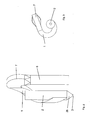
- the device described above will be formed as a multi-stage and / or multi-strand arrangement with a plurality of helical and / or spiral lines and associated gas lines.
- a three-stage arrangement is schematically shown in FIGS 4 and FIG. 5 shown. These are in particular a lower stage I, a middle stage II and an upper stage III, wherein in each case the gas line 2 of a further down stage in the helical or spiral line 1 passes over a step above.
- the gas line 2 "of the uppermost stage III is connected, for example, for dedusting to a filter or to a downstream high-efficiency separator Solid lines 3 behaves accordingly reversed.
- the solid line 3 "of the uppermost stage III is connected to the spiral line 1 leading to the middle stage II gas line 2, while the solid line of the middle stage II with the spiral or spiral line 1 of the lower stage
- the solid line 3 of the lowest stage I is connected to a subsequent aggregate, for example a calciner or a rotary kiln, in this way one can lead into the spiral and / or spiral line 1 "of the uppermost stage III Gas line introduced solid are heat treated in a hot gas stream.
- the individual stages of the multi-stage arrangement can be arranged intertwined due to the helical or spiral lines, so that there is a very compact overall arrangement in the vertical direction.
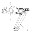
- FIG. 6 shows a three-dimensional representation of a plant for heat treatment of fine-grained material in cement production with a rotary kiln 10, a calciner 20 and a preheater 30.
- the calciner 20 and / or the preheater 30 can according to the in FIGS. 1 to 5 be formed device described.
Landscapes
- Chemical & Material Sciences (AREA)
- Engineering & Computer Science (AREA)
- Ceramic Engineering (AREA)
- Materials Engineering (AREA)
- Organic Chemistry (AREA)
- Physics & Mathematics (AREA)
- Thermal Sciences (AREA)
- Mechanical Engineering (AREA)
- Chemical Kinetics & Catalysis (AREA)
- Structural Engineering (AREA)
- General Engineering & Computer Science (AREA)
- Separating Particles In Gases By Inertia (AREA)
- Curing Cements, Concrete, And Artificial Stone (AREA)
- Cyclones (AREA)
- Devices And Processes Conducted In The Presence Of Fluids And Solid Particles (AREA)
- Physical Or Chemical Processes And Apparatus (AREA)
- Silicon Compounds (AREA)
- Branch Pipes, Bends, And The Like (AREA)
Applications Claiming Priority (2)
| Application Number | Priority Date | Filing Date | Title |
|---|---|---|---|
| DE102007037281 | 2007-08-07 | ||
| PCT/EP2008/058100 WO2009019070A1 (de) | 2007-08-07 | 2008-06-25 | Vorrichtung und verfahren zur durchführung chemischer und/oder physikalischer reaktionen zwischen einem feststoff und einem gas sowie anlage zur zementherstellung |
Publications (2)
| Publication Number | Publication Date |
|---|---|
| EP2106519A1 EP2106519A1 (de) | 2009-10-07 |
| EP2106519B1 true EP2106519B1 (de) | 2011-08-17 |
Family
ID=39790969
Family Applications (3)
| Application Number | Title | Priority Date | Filing Date |
|---|---|---|---|
| EP08774293A Not-in-force EP2106519B1 (de) | 2007-08-07 | 2008-06-25 | Vorrichtung und verfahren zur durchführung chemischer und/oder physikalischer reaktionen zwischen einem feststoff und einem gas sowie anlage zur zementherstellung |
| EP08761374A Not-in-force EP2174086B1 (de) | 2007-08-07 | 2008-06-25 | Vorrichtung zur durchführung chemischer und/oder physikalischer reaktionen zwischen einem feststoff und einem gas |
| EP08761375A Not-in-force EP2106518B1 (de) | 2007-08-07 | 2008-06-25 | Vorrichtung zur separierung von einem feststoff und einem gas sowie anlage zur zementherstellung |
Family Applications After (2)
| Application Number | Title | Priority Date | Filing Date |
|---|---|---|---|
| EP08761374A Not-in-force EP2174086B1 (de) | 2007-08-07 | 2008-06-25 | Vorrichtung zur durchführung chemischer und/oder physikalischer reaktionen zwischen einem feststoff und einem gas |
| EP08761375A Not-in-force EP2106518B1 (de) | 2007-08-07 | 2008-06-25 | Vorrichtung zur separierung von einem feststoff und einem gas sowie anlage zur zementherstellung |
Country Status (12)
| Country | Link |
|---|---|
| US (2) | US8439670B2 (enExample) |
| EP (3) | EP2106519B1 (enExample) |
| JP (2) | JP2010535687A (enExample) |
| CN (2) | CN101772686B (enExample) |
| AT (3) | ATE492779T1 (enExample) |
| BR (2) | BRPI0813805A2 (enExample) |
| CA (2) | CA2691869A1 (enExample) |
| DE (1) | DE502008002099D1 (enExample) |
| DK (1) | DK2106519T3 (enExample) |
| ES (1) | ES2370092T3 (enExample) |
| RU (2) | RU2477430C2 (enExample) |
| WO (3) | WO2009019072A1 (enExample) |
Families Citing this family (3)
| Publication number | Priority date | Publication date | Assignee | Title |
|---|---|---|---|---|
| US20110097679A1 (en) * | 2008-06-25 | 2011-04-28 | Verena Georg | Device for performing chemical and/or physical reactions between a solid material and a gas |
| US11059049B2 (en) | 2016-07-21 | 2021-07-13 | Superior Industries, Inc. | Classifying apparatus, systems and methods |
| CA3031406C (en) * | 2016-07-21 | 2024-06-18 | Superior Industries, Inc. | Classifying apparatus, systems and methods |
Family Cites Families (44)
| Publication number | Priority date | Publication date | Assignee | Title |
|---|---|---|---|---|
| US2878891A (en) * | 1953-10-05 | 1959-03-24 | Exxon Research Engineering Co | Loop separator for gases and solids |
| FR95046E (fr) * | 1964-10-05 | 1970-03-27 | Creusot Forges Ateliers | Perfectionnements aux installations de préchauffage de substances pulvérulentes par les gaz d'échappement d'un four de traitement de ces substances. |
| DE2324519C3 (de) * | 1973-05-15 | 1982-07-08 | Krupp Polysius Ag, 4720 Beckum | Verfahren und Vorrichtungen zur Wärmebehandlung von feinkörnigem Gut |
| GB1446241A (en) * | 1974-03-22 | 1976-08-18 | Smdth Co As F L | Method of and plant for calcinating pulverous raw material |
| GB1506733A (en) * | 1974-03-29 | 1978-04-12 | Lafarge Sa | Method of treating raw material for producing cement |
| JPS532646B2 (enExample) * | 1974-09-30 | 1978-01-30 | ||
| GB1510392A (en) * | 1976-01-19 | 1978-05-10 | Ass Portland Cement | Portland cement manufacture and utilisation of waste matter |
| US4201546A (en) * | 1976-07-09 | 1980-05-06 | Klockner-Humboldt-Deutz Aktiengesellschaft | Method and apparatus for the thermal treatment of alkali-containing pulverized raw material to be used in the manufacture of cement |
| DE2724654C2 (de) * | 1977-06-01 | 1984-01-26 | Klöckner-Humboldt-Deutz AG, 5000 Köln | Verfahren und Einrichtung zum Brennen von feinkörnigem bis staubförmigem Gut, insbesondere von Zementrohmehl |
| DE2744042C2 (de) * | 1977-09-30 | 1984-09-06 | Klöckner-Humboldt-Deutz AG, 5000 Köln | Wärmetauscher zur thermischen Behandlung von feinkörnigem Gut |
| DE2745425C3 (de) * | 1977-10-08 | 1986-02-13 | Klöckner-Humboldt-Deutz AG, 5000 Köln | Verfahren und Vorrichtung zur Aufbereitung von Kohle in einer Luftstrom-Mahltrocknungs-Anlage |
| DE2815461C2 (de) * | 1978-04-10 | 1987-01-29 | Klöckner-Humboldt-Deutz AG, 5000 Köln | Verfahren und Vorrichtung zur thermischen Behandlung von feinkörnigem Gut mit heißen Gasen |
| US4318697A (en) | 1979-02-02 | 1982-03-09 | Itzhak Shoher | Dental restorative anterior structure |
| FR2452954A1 (fr) * | 1979-04-02 | 1980-10-31 | Lab | Perfectionnements aux separateurs centrifuges |
| US4288235A (en) * | 1979-07-06 | 1981-09-08 | Stone & Webster Engineering Corporation | Low residence time solid-gas separation device and system |
| JPS5934271B2 (ja) * | 1980-01-21 | 1984-08-21 | 株式会社神戸製鋼所 | 粉粒体と気体との熱交換方法及びその装置 |
| JPS6014494Y2 (ja) * | 1980-02-29 | 1985-05-09 | 株式会社神戸製鋼所 | 粉粒体と気体との熱交換分離ユニツト |
| US4318692A (en) * | 1981-01-02 | 1982-03-09 | Allis-Chalmers Corporation | Helical duct gas/meal separator |
| JPS6014496Y2 (ja) * | 1981-07-29 | 1985-05-09 | 株式会社神戸製鋼所 | 粉粒体と気体との熱交換ユニツト |
| AT378170B (de) * | 1982-04-16 | 1985-06-25 | Perlmooser Zementwerke Ag | Verfahren zur herstellung von zementklinker |
| JPS5949817A (ja) * | 1982-09-14 | 1984-03-22 | Nippon Cement Co Ltd | 分離機 |
| SE437943B (sv) * | 1983-08-16 | 1985-03-25 | Stal Laval Turbin Ab | Sett att oka en cyklons avskiljningsgrad och cyklonavskiljare for genomforande av settet |
| DE3333718A1 (de) * | 1983-09-17 | 1985-04-04 | Klöckner-Humboldt-Deutz AG, 5000 Köln | Anlage zum brennen von feinkoernigem gut, insbesondere zu zementklinker |
| DE3507371A1 (de) * | 1985-03-02 | 1986-09-04 | Norddeutsche Affinerie AG, 2000 Hamburg | Vorrichtung fuer die pyrometallurgische behandlung feinkoerniger, schmelzfluessige produkte ergebender feststoffe |
| DE3538707A1 (de) * | 1985-10-31 | 1987-05-07 | Kloeckner Humboldt Deutz Ag | Verfahren und vorrichtung zur thermischen behandlung von mehlfoermigen rohmaterialien |
| DE3580488D1 (de) * | 1985-12-09 | 1990-12-13 | Ahlstroem Oy | Reaktor mit zirkulierendem wirbelbett, verfahren zum trennen von feststoffen aus rauchgas. |
| DE3612031A1 (de) | 1986-04-10 | 1987-10-22 | Krupp Polysius Ag | Verfahren und anlage zur waermebehandlung von pulverfoermigem rohmaterial |
| GB2227301A (en) * | 1989-01-18 | 1990-07-25 | Smidth & Co As F L | Method and apparatus for producing cement clinker |
| DE4002553A1 (de) * | 1990-01-30 | 1991-08-01 | Kloeckner Humboldt Deutz Ag | Verfahren und anlage zur waermebehandlung von feinkoernigem gut, insbesondere zur herstellung von zementklinker |
| JPH10508245A (ja) * | 1994-10-06 | 1998-08-18 | アーノルド,エードリアン クリストファー | 粒子状物質の除去 |
| DE4435871A1 (de) * | 1994-10-07 | 1996-04-11 | Heidelberger Zement Ag | Schwebegaswärmetauscher als Vorschaltstufe vor einen Trockendrehofen zum Brennen von Zementklinker oder dergleichen |
| RU2080939C1 (ru) * | 1995-01-26 | 1997-06-10 | Анатолий Васильевич Тананаев | Инерционный фильтр-сепаратор |
| GB9608341D0 (en) * | 1996-04-23 | 1996-06-26 | Blue Circle Ind Plc | Disposal of waste tyres |
| US6210154B1 (en) * | 1997-04-22 | 2001-04-03 | Blue Circle Industries, Inc. | Treatment of exhaust gases from kilns |
| EP0882687B1 (en) * | 1997-06-02 | 2000-03-15 | Joseph E. Dipl.-Ing. Doumet | Method and apparatus for producing cement clinker |
| DE19854582B4 (de) * | 1998-11-25 | 2007-11-22 | Khd Humboldt Wedag Gmbh | Verfahren zur thermischen Behandlung von Zementrohmehl |
| CN1100978C (zh) * | 1999-04-21 | 2003-02-05 | 镇江市电站辅机厂 | 一种锅炉底灰渣的冷却方法及其冷却装置 |
| JP2000304229A (ja) * | 1999-04-23 | 2000-11-02 | Mitsubishi Heavy Ind Ltd | 焼却炉 |
| JP3065120U (ja) * | 1999-06-23 | 2000-01-28 | 日本建設工業株式会社 | 圧縮空気の除湿装置 |
| TW487689B (en) * | 2000-03-30 | 2002-05-21 | Smidth & Co As F L | Method and apparatus for manufacturing cement clinker from particulate cement raw material |
| DE10309575A1 (de) * | 2003-03-05 | 2004-09-30 | OCé PRINTING SYSTEMS GMBH | Zyklotron zur Abscheidung von Partikeln aus einem Gas-Partikel-Gemisch |
| CN2675648Y (zh) * | 2003-12-12 | 2005-02-02 | 青岛市团岛污水处理厂 | 污水处理用浮渣收集设备 |
| CN2815487Y (zh) * | 2005-08-12 | 2006-09-13 | 周凤举 | 带迷宫螺旋翅片导流挡板的内返流塔式流化床反应器 |
| JP2007136340A (ja) * | 2005-11-18 | 2007-06-07 | Idemitsu Kosan Co Ltd | 粉粒物分離装置、その方法、気体分析装置、および、ガス処理装置 |
-
2008
- 2008-06-25 US US12/672,525 patent/US8439670B2/en not_active Expired - Fee Related
- 2008-06-25 JP JP2010519392A patent/JP2010535687A/ja active Pending
- 2008-06-25 US US12/672,530 patent/US8454715B2/en not_active Expired - Fee Related
- 2008-06-25 AT AT08761374T patent/ATE492779T1/de active
- 2008-06-25 CA CA002691869A patent/CA2691869A1/en not_active Abandoned
- 2008-06-25 AT AT08761375T patent/ATE532019T1/de active
- 2008-06-25 EP EP08774293A patent/EP2106519B1/de not_active Not-in-force
- 2008-06-25 CN CN2008801020306A patent/CN101772686B/zh not_active Expired - Fee Related
- 2008-06-25 BR BRPI0813805-2A2A patent/BRPI0813805A2/pt not_active IP Right Cessation
- 2008-06-25 CN CN200880102000.5A patent/CN101849155B/zh not_active Expired - Fee Related
- 2008-06-25 RU RU2010108293/02A patent/RU2477430C2/ru not_active IP Right Cessation
- 2008-06-25 JP JP2010519393A patent/JP2010535688A/ja active Pending
- 2008-06-25 RU RU2010108294/02A patent/RU2463540C2/ru not_active IP Right Cessation
- 2008-06-25 CA CA002691834A patent/CA2691834A1/en not_active Abandoned
- 2008-06-25 WO PCT/EP2008/058105 patent/WO2009019072A1/de not_active Ceased
- 2008-06-25 BR BRPI0812852-9A2A patent/BRPI0812852A2/pt not_active IP Right Cessation
- 2008-06-25 WO PCT/EP2008/058100 patent/WO2009019070A1/de not_active Ceased
- 2008-06-25 EP EP08761374A patent/EP2174086B1/de not_active Not-in-force
- 2008-06-25 EP EP08761375A patent/EP2106518B1/de not_active Not-in-force
- 2008-06-25 WO PCT/EP2008/058104 patent/WO2009019071A1/de not_active Ceased
- 2008-06-25 AT AT08774293T patent/ATE520942T1/de active
- 2008-06-25 DE DE502008002099T patent/DE502008002099D1/de active Active
- 2008-06-25 ES ES08774293T patent/ES2370092T3/es active Active
- 2008-06-25 DK DK08774293.8T patent/DK2106519T3/da active
Also Published As
| Publication number | Publication date |
|---|---|
| WO2009019071A1 (de) | 2009-02-12 |
| ATE492779T1 (de) | 2011-01-15 |
| US20110209449A1 (en) | 2011-09-01 |
| RU2010108293A (ru) | 2011-09-20 |
| ATE520942T1 (de) | 2011-09-15 |
| WO2009019070A1 (de) | 2009-02-12 |
| DK2106519T3 (da) | 2011-12-05 |
| EP2106518A1 (de) | 2009-10-07 |
| CN101849155A (zh) | 2010-09-29 |
| US8454715B2 (en) | 2013-06-04 |
| BRPI0813805A2 (pt) | 2014-12-30 |
| EP2106519A1 (de) | 2009-10-07 |
| CA2691869A1 (en) | 2009-02-12 |
| RU2010108294A (ru) | 2011-09-20 |
| EP2174086B1 (de) | 2010-12-22 |
| JP2010535688A (ja) | 2010-11-25 |
| EP2106518B1 (de) | 2011-11-02 |
| ES2370092T3 (es) | 2011-12-12 |
| CN101772686B (zh) | 2012-04-04 |
| CN101849155B (zh) | 2013-04-10 |
| RU2463540C2 (ru) | 2012-10-10 |
| US8439670B2 (en) | 2013-05-14 |
| CN101772686A (zh) | 2010-07-07 |
| JP2010535687A (ja) | 2010-11-25 |
| BRPI0812852A2 (pt) | 2014-12-09 |
| EP2174086A1 (de) | 2010-04-14 |
| WO2009019072A1 (de) | 2009-02-12 |
| US20110293487A1 (en) | 2011-12-01 |
| DE502008002099D1 (de) | 2011-02-03 |
| RU2477430C2 (ru) | 2013-03-10 |
| CA2691834A1 (en) | 2009-02-12 |
| ATE532019T1 (de) | 2011-11-15 |
Similar Documents
| Publication | Publication Date | Title |
|---|---|---|
| DE69825854T2 (de) | Verfahren und vorrichtung zur kühlung von bypass abgasen vom ofen | |
| EP2812122B1 (de) | Verfahren zur feinstoffreduktion im rea-gips | |
| AT516856B1 (de) | Hydrozyklon mit Feinstoffabreicherung im Zyklonunterlauf | |
| EP2106519B1 (de) | Vorrichtung und verfahren zur durchführung chemischer und/oder physikalischer reaktionen zwischen einem feststoff und einem gas sowie anlage zur zementherstellung | |
| DE3106889A1 (de) | "vorrichtung zum auftrennen einer mischung aus einer cellulosebreisuspension und groben schweren teilchen" | |
| EP2288861B1 (de) | Vorrichtung zur durchführung chemischer und/oder physikalischer reaktionen zwischen einem feststoff und einem gas | |
| DE102009050165A1 (de) | Vorrichtung zur Behandlung von Feststoffen und/oder Gasen | |
| DE602004007818T2 (de) | Verfahren und anlage zum vorerhitzen von teilchen- oder pulverförmigem material | |
| DE2401735C2 (de) | Vorrichtung zum Klassieren von in einem Trägerfluid dispergierten Feststoffteilchen | |
| DE2605042A1 (de) | Waermetauscher zur thermischen behandlung von feinkoernigen, feuchten materialien | |
| EP2195595B1 (de) | Vorrichtung zur durchführung chemischer und/oder physikalischer reaktionen zwischen einem feststoff und einem gas | |
| WO2009155975A1 (de) | Vorrichtung zur separierung von einem feststoff und einem gas sowie anlage zur zementherstellung | |
| WO2009155974A1 (de) | Vorrichtung zur separierung von einem feststoff und einem gas sowie anlage zur zementherstellung | |
| DE3149389C2 (de) | Vorrichtung zum Calcinieren von Materialien in Form von Pulver oder Teilchen | |
| EP4271954B1 (de) | Höhenoptimierte vorrichtung zur wärmebehandlung von mineralischen stoffen | |
| EP0342340B1 (de) | Schwebegas-Wärmetauscher | |
| DE19963284A1 (de) | Hydrozyklonanordnung | |
| DE29709918U1 (de) | Vorrichtung zum Ausscheiden von Fein- und Leichtgut aus trockenem, rieselfähigem Schüttgut | |
| WO2009155976A1 (de) | Vorrichtung zur separierung von einem feststoff und einem gas sowie anlage zur zementherstellung | |
| DE2257428C3 (enExample) | ||
| EP1844283B1 (de) | Mehrstufiger wärmetauscher und zyklonabscheider zum einsatz in einem solchen wärmetauscher | |
| DE3024837C2 (de) | Teilchenabscheider mit vertikaler Achse | |
| EP2397220B1 (de) | Strömungsgenerator | |
| DE2540338A1 (de) | Vorrichtung zur kalzinierung von feinkoernigen und pulverfoermigen materialien, insbesondere zementrohstoff | |
| DE8207025U1 (de) | Suspensionswaermetauscher |
Legal Events
| Date | Code | Title | Description |
|---|---|---|---|
| PUAI | Public reference made under article 153(3) epc to a published international application that has entered the european phase |
Free format text: ORIGINAL CODE: 0009012 |
|
| 17P | Request for examination filed |
Effective date: 20090826 |
|
| AK | Designated contracting states |
Kind code of ref document: A1 Designated state(s): AT BE BG CH CY CZ DE DK EE ES FI FR GB GR HR HU IE IS IT LI LT LU LV MC MT NL NO PL PT RO SE SI SK TR |
|
| RIN1 | Information on inventor provided before grant (corrected) |
Inventor name: VOELLINK, MARCO Inventor name: LAGAR GARCIA, LUIS Inventor name: THIEMEYER, HEINZ-WERNER Inventor name: KUPPER, DETLEV Inventor name: HOPPE, ANDREAS Inventor name: GEORG, VERENA |
|
| RIN1 | Information on inventor provided before grant (corrected) |
Inventor name: GEORG, VERENA Inventor name: VOELLINK, MARCO Inventor name: KUPPER, DETLEV Inventor name: THIEMEYER, HEINZ-WERNER Inventor name: LAGAR GARCIA, LUIS Inventor name: HOPPE, ANDREAS |
|
| GRAJ | Information related to disapproval of communication of intention to grant by the applicant or resumption of examination proceedings by the epo deleted |
Free format text: ORIGINAL CODE: EPIDOSDIGR1 |
|
| GRAP | Despatch of communication of intention to grant a patent |
Free format text: ORIGINAL CODE: EPIDOSNIGR1 |
|
| GRAP | Despatch of communication of intention to grant a patent |
Free format text: ORIGINAL CODE: EPIDOSNIGR1 |
|
| DAX | Request for extension of the european patent (deleted) | ||
| RAP1 | Party data changed (applicant data changed or rights of an application transferred) |
Owner name: POLYSIUS AG |
|
| GRAC | Information related to communication of intention to grant a patent modified |
Free format text: ORIGINAL CODE: EPIDOSCIGR1 |
|
| GRAS | Grant fee paid |
Free format text: ORIGINAL CODE: EPIDOSNIGR3 |
|
| GRAA | (expected) grant |
Free format text: ORIGINAL CODE: 0009210 |
|
| AK | Designated contracting states |
Kind code of ref document: B1 Designated state(s): AT BE BG CH CY CZ DE DK EE ES FI FR GB GR HR HU IE IS IT LI LT LU LV MC MT NL NO PL PT RO SE SI SK TR |
|
| REG | Reference to a national code |
Ref country code: GB Ref legal event code: FG4D Free format text: NOT ENGLISH |
|
| RAP2 | Party data changed (patent owner data changed or rights of a patent transferred) |
Owner name: THYSSENKRUPP POLYSIUS AG |
|
| REG | Reference to a national code |
Ref country code: CH Ref legal event code: EP |
|
| REG | Reference to a national code |
Ref country code: IE Ref legal event code: FG4D Free format text: LANGUAGE OF EP DOCUMENT: GERMAN |
|
| REG | Reference to a national code |
Ref country code: DE Ref legal event code: R096 Ref document number: 502008004548 Country of ref document: DE Effective date: 20111013 |
|
| REG | Reference to a national code |
Ref country code: DE Ref legal event code: R081 Ref document number: 502008004548 Country of ref document: DE Owner name: THYSSENKRUPP POLYSIUS AG, DE Free format text: FORMER OWNER: THYSSENKRUPP POLYSIUS AG, 59269 BECKUM, DE Effective date: 20110921 |
|
| REG | Reference to a national code |
Ref country code: DK Ref legal event code: T3 |
|
| REG | Reference to a national code |
Ref country code: NL Ref legal event code: VDEP Effective date: 20110817 |
|
| REG | Reference to a national code |
Ref country code: ES Ref legal event code: FG2A Ref document number: 2370092 Country of ref document: ES Kind code of ref document: T3 Effective date: 20111212 |
|
| LTIE | Lt: invalidation of european patent or patent extension |
Effective date: 20110817 |
|
| PG25 | Lapsed in a contracting state [announced via postgrant information from national office to epo] |
Ref country code: HR Free format text: LAPSE BECAUSE OF FAILURE TO SUBMIT A TRANSLATION OF THE DESCRIPTION OR TO PAY THE FEE WITHIN THE PRESCRIBED TIME-LIMIT Effective date: 20110831 Ref country code: PT Free format text: LAPSE BECAUSE OF FAILURE TO SUBMIT A TRANSLATION OF THE DESCRIPTION OR TO PAY THE FEE WITHIN THE PRESCRIBED TIME-LIMIT Effective date: 20111219 Ref country code: IS Free format text: LAPSE BECAUSE OF FAILURE TO SUBMIT A TRANSLATION OF THE DESCRIPTION OR TO PAY THE FEE WITHIN THE PRESCRIBED TIME-LIMIT Effective date: 20111217 Ref country code: NO Free format text: LAPSE BECAUSE OF FAILURE TO SUBMIT A TRANSLATION OF THE DESCRIPTION OR TO PAY THE FEE WITHIN THE PRESCRIBED TIME-LIMIT Effective date: 20111117 Ref country code: SE Free format text: LAPSE BECAUSE OF FAILURE TO SUBMIT A TRANSLATION OF THE DESCRIPTION OR TO PAY THE FEE WITHIN THE PRESCRIBED TIME-LIMIT Effective date: 20110817 Ref country code: LT Free format text: LAPSE BECAUSE OF FAILURE TO SUBMIT A TRANSLATION OF THE DESCRIPTION OR TO PAY THE FEE WITHIN THE PRESCRIBED TIME-LIMIT Effective date: 20110817 Ref country code: NL Free format text: LAPSE BECAUSE OF FAILURE TO SUBMIT A TRANSLATION OF THE DESCRIPTION OR TO PAY THE FEE WITHIN THE PRESCRIBED TIME-LIMIT Effective date: 20110817 Ref country code: FI Free format text: LAPSE BECAUSE OF FAILURE TO SUBMIT A TRANSLATION OF THE DESCRIPTION OR TO PAY THE FEE WITHIN THE PRESCRIBED TIME-LIMIT Effective date: 20110817 |
|
| PG25 | Lapsed in a contracting state [announced via postgrant information from national office to epo] |
Ref country code: GR Free format text: LAPSE BECAUSE OF FAILURE TO SUBMIT A TRANSLATION OF THE DESCRIPTION OR TO PAY THE FEE WITHIN THE PRESCRIBED TIME-LIMIT Effective date: 20111118 Ref country code: PL Free format text: LAPSE BECAUSE OF FAILURE TO SUBMIT A TRANSLATION OF THE DESCRIPTION OR TO PAY THE FEE WITHIN THE PRESCRIBED TIME-LIMIT Effective date: 20110817 Ref country code: SI Free format text: LAPSE BECAUSE OF FAILURE TO SUBMIT A TRANSLATION OF THE DESCRIPTION OR TO PAY THE FEE WITHIN THE PRESCRIBED TIME-LIMIT Effective date: 20110817 Ref country code: CY Free format text: LAPSE BECAUSE OF FAILURE TO SUBMIT A TRANSLATION OF THE DESCRIPTION OR TO PAY THE FEE WITHIN THE PRESCRIBED TIME-LIMIT Effective date: 20110817 Ref country code: LV Free format text: LAPSE BECAUSE OF FAILURE TO SUBMIT A TRANSLATION OF THE DESCRIPTION OR TO PAY THE FEE WITHIN THE PRESCRIBED TIME-LIMIT Effective date: 20110817 |
|
| REG | Reference to a national code |
Ref country code: IE Ref legal event code: FD4D |
|
| PG25 | Lapsed in a contracting state [announced via postgrant information from national office to epo] |
Ref country code: IE Free format text: LAPSE BECAUSE OF FAILURE TO SUBMIT A TRANSLATION OF THE DESCRIPTION OR TO PAY THE FEE WITHIN THE PRESCRIBED TIME-LIMIT Effective date: 20110817 Ref country code: SK Free format text: LAPSE BECAUSE OF FAILURE TO SUBMIT A TRANSLATION OF THE DESCRIPTION OR TO PAY THE FEE WITHIN THE PRESCRIBED TIME-LIMIT Effective date: 20110817 |
|
| PG25 | Lapsed in a contracting state [announced via postgrant information from national office to epo] |
Ref country code: EE Free format text: LAPSE BECAUSE OF FAILURE TO SUBMIT A TRANSLATION OF THE DESCRIPTION OR TO PAY THE FEE WITHIN THE PRESCRIBED TIME-LIMIT Effective date: 20110817 Ref country code: RO Free format text: LAPSE BECAUSE OF FAILURE TO SUBMIT A TRANSLATION OF THE DESCRIPTION OR TO PAY THE FEE WITHIN THE PRESCRIBED TIME-LIMIT Effective date: 20110817 |
|
| PLBE | No opposition filed within time limit |
Free format text: ORIGINAL CODE: 0009261 |
|
| STAA | Information on the status of an ep patent application or granted ep patent |
Free format text: STATUS: NO OPPOSITION FILED WITHIN TIME LIMIT |
|
| 26N | No opposition filed |
Effective date: 20120521 |
|
| PGFP | Annual fee paid to national office [announced via postgrant information from national office to epo] |
Ref country code: DK Payment date: 20120620 Year of fee payment: 5 Ref country code: CZ Payment date: 20120619 Year of fee payment: 5 |
|
| PGFP | Annual fee paid to national office [announced via postgrant information from national office to epo] |
Ref country code: FR Payment date: 20120705 Year of fee payment: 5 |
|
| REG | Reference to a national code |
Ref country code: DE Ref legal event code: R097 Ref document number: 502008004548 Country of ref document: DE Effective date: 20120521 |
|
| PGFP | Annual fee paid to national office [announced via postgrant information from national office to epo] |
Ref country code: IT Payment date: 20120626 Year of fee payment: 5 |
|
| BERE | Be: lapsed |
Owner name: POLYSIUS A.G. Effective date: 20120630 |
|
| PGFP | Annual fee paid to national office [announced via postgrant information from national office to epo] |
Ref country code: ES Payment date: 20120627 Year of fee payment: 5 Ref country code: DE Payment date: 20120703 Year of fee payment: 5 |
|
| PG25 | Lapsed in a contracting state [announced via postgrant information from national office to epo] |
Ref country code: MC Free format text: LAPSE BECAUSE OF NON-PAYMENT OF DUE FEES Effective date: 20120630 |
|
| REG | Reference to a national code |
Ref country code: CH Ref legal event code: PL |
|
| REG | Reference to a national code |
Ref country code: CH Ref legal event code: PL |
|
| GBPC | Gb: european patent ceased through non-payment of renewal fee |
Effective date: 20120625 |
|
| PG25 | Lapsed in a contracting state [announced via postgrant information from national office to epo] |
Ref country code: BE Free format text: LAPSE BECAUSE OF NON-PAYMENT OF DUE FEES Effective date: 20120630 Ref country code: CH Free format text: LAPSE BECAUSE OF NON-PAYMENT OF DUE FEES Effective date: 20120630 Ref country code: GB Free format text: LAPSE BECAUSE OF NON-PAYMENT OF DUE FEES Effective date: 20120625 Ref country code: LI Free format text: LAPSE BECAUSE OF NON-PAYMENT OF DUE FEES Effective date: 20120630 |
|
| PG25 | Lapsed in a contracting state [announced via postgrant information from national office to epo] |
Ref country code: BG Free format text: LAPSE BECAUSE OF FAILURE TO SUBMIT A TRANSLATION OF THE DESCRIPTION OR TO PAY THE FEE WITHIN THE PRESCRIBED TIME-LIMIT Effective date: 20111117 |
|
| PG25 | Lapsed in a contracting state [announced via postgrant information from national office to epo] |
Ref country code: MT Free format text: LAPSE BECAUSE OF FAILURE TO SUBMIT A TRANSLATION OF THE DESCRIPTION OR TO PAY THE FEE WITHIN THE PRESCRIBED TIME-LIMIT Effective date: 20110817 |
|
| PG25 | Lapsed in a contracting state [announced via postgrant information from national office to epo] |
Ref country code: HR Free format text: LAPSE BECAUSE OF FAILURE TO SUBMIT A TRANSLATION OF THE DESCRIPTION OR TO PAY THE FEE WITHIN THE PRESCRIBED TIME-LIMIT Effective date: 20110817 |
|
| PG25 | Lapsed in a contracting state [announced via postgrant information from national office to epo] |
Ref country code: CZ Free format text: LAPSE BECAUSE OF NON-PAYMENT OF DUE FEES Effective date: 20130625 |
|
| REG | Reference to a national code |
Ref country code: DK Ref legal event code: EBP Effective date: 20130630 |
|
| REG | Reference to a national code |
Ref country code: DE Ref legal event code: R119 Ref document number: 502008004548 Country of ref document: DE Effective date: 20140101 |
|
| REG | Reference to a national code |
Ref country code: FR Ref legal event code: ST Effective date: 20140228 |
|
| PG25 | Lapsed in a contracting state [announced via postgrant information from national office to epo] |
Ref country code: TR Free format text: LAPSE BECAUSE OF FAILURE TO SUBMIT A TRANSLATION OF THE DESCRIPTION OR TO PAY THE FEE WITHIN THE PRESCRIBED TIME-LIMIT Effective date: 20110817 Ref country code: DE Free format text: LAPSE BECAUSE OF NON-PAYMENT OF DUE FEES Effective date: 20140101 |
|
| PG25 | Lapsed in a contracting state [announced via postgrant information from national office to epo] |
Ref country code: FR Free format text: LAPSE BECAUSE OF NON-PAYMENT OF DUE FEES Effective date: 20130701 Ref country code: IT Free format text: LAPSE BECAUSE OF NON-PAYMENT OF DUE FEES Effective date: 20130625 Ref country code: LU Free format text: LAPSE BECAUSE OF NON-PAYMENT OF DUE FEES Effective date: 20120625 |
|
| REG | Reference to a national code |
Ref country code: ES Ref legal event code: FD2A Effective date: 20140708 |
|
| PG25 | Lapsed in a contracting state [announced via postgrant information from national office to epo] |
Ref country code: HU Free format text: LAPSE BECAUSE OF FAILURE TO SUBMIT A TRANSLATION OF THE DESCRIPTION OR TO PAY THE FEE WITHIN THE PRESCRIBED TIME-LIMIT Effective date: 20080625 |
|
| REG | Reference to a national code |
Ref country code: AT Ref legal event code: MM01 Ref document number: 520942 Country of ref document: AT Kind code of ref document: T Effective date: 20130625 |
|
| PG25 | Lapsed in a contracting state [announced via postgrant information from national office to epo] |
Ref country code: DK Free format text: LAPSE BECAUSE OF NON-PAYMENT OF DUE FEES Effective date: 20130630 |
|
| PG25 | Lapsed in a contracting state [announced via postgrant information from national office to epo] |
Ref country code: AT Free format text: LAPSE BECAUSE OF NON-PAYMENT OF DUE FEES Effective date: 20130625 Ref country code: ES Free format text: LAPSE BECAUSE OF NON-PAYMENT OF DUE FEES Effective date: 20130626 |