EP2105330B1 - Dispositif de commande d'un système de suspension - Google Patents
Dispositif de commande d'un système de suspension Download PDFInfo
- Publication number
- EP2105330B1 EP2105330B1 EP09154852A EP09154852A EP2105330B1 EP 2105330 B1 EP2105330 B1 EP 2105330B1 EP 09154852 A EP09154852 A EP 09154852A EP 09154852 A EP09154852 A EP 09154852A EP 2105330 B1 EP2105330 B1 EP 2105330B1
- Authority
- EP
- European Patent Office
- Prior art keywords
- wheel
- vehicle
- damping force
- damper
- control
- Prior art date
- Legal status (The legal status is an assumption and is not a legal conclusion. Google has not performed a legal analysis and makes no representation as to the accuracy of the status listed.)
- Expired - Fee Related
Links
Images


Classifications
-
- B—PERFORMING OPERATIONS; TRANSPORTING
- B60—VEHICLES IN GENERAL
- B60G—VEHICLE SUSPENSION ARRANGEMENTS
- B60G17/00—Resilient suspensions having means for adjusting the spring or vibration-damper characteristics, for regulating the distance between a supporting surface and a sprung part of vehicle or for locking suspension during use to meet varying vehicular or surface conditions, e.g. due to speed or load
- B60G17/015—Resilient suspensions having means for adjusting the spring or vibration-damper characteristics, for regulating the distance between a supporting surface and a sprung part of vehicle or for locking suspension during use to meet varying vehicular or surface conditions, e.g. due to speed or load the regulating means comprising electric or electronic elements
- B60G17/016—Resilient suspensions having means for adjusting the spring or vibration-damper characteristics, for regulating the distance between a supporting surface and a sprung part of vehicle or for locking suspension during use to meet varying vehicular or surface conditions, e.g. due to speed or load the regulating means comprising electric or electronic elements characterised by their responsiveness, when the vehicle is travelling, to specific motion, a specific condition, or driver input
-
- B—PERFORMING OPERATIONS; TRANSPORTING
- B60—VEHICLES IN GENERAL
- B60G—VEHICLE SUSPENSION ARRANGEMENTS
- B60G17/00—Resilient suspensions having means for adjusting the spring or vibration-damper characteristics, for regulating the distance between a supporting surface and a sprung part of vehicle or for locking suspension during use to meet varying vehicular or surface conditions, e.g. due to speed or load
- B60G17/015—Resilient suspensions having means for adjusting the spring or vibration-damper characteristics, for regulating the distance between a supporting surface and a sprung part of vehicle or for locking suspension during use to meet varying vehicular or surface conditions, e.g. due to speed or load the regulating means comprising electric or electronic elements
- B60G17/018—Resilient suspensions having means for adjusting the spring or vibration-damper characteristics, for regulating the distance between a supporting surface and a sprung part of vehicle or for locking suspension during use to meet varying vehicular or surface conditions, e.g. due to speed or load the regulating means comprising electric or electronic elements characterised by the use of a specific signal treatment or control method
-
- B—PERFORMING OPERATIONS; TRANSPORTING
- B60—VEHICLES IN GENERAL
- B60G—VEHICLE SUSPENSION ARRANGEMENTS
- B60G2400/00—Indexing codes relating to detected, measured or calculated conditions or factors
- B60G2400/05—Attitude
- B60G2400/052—Angular rate
- B60G2400/0523—Yaw rate
-
- B—PERFORMING OPERATIONS; TRANSPORTING
- B60—VEHICLES IN GENERAL
- B60G—VEHICLE SUSPENSION ARRANGEMENTS
- B60G2400/00—Indexing codes relating to detected, measured or calculated conditions or factors
- B60G2400/10—Acceleration; Deceleration
- B60G2400/102—Acceleration; Deceleration vertical
-
- B—PERFORMING OPERATIONS; TRANSPORTING
- B60—VEHICLES IN GENERAL
- B60G—VEHICLE SUSPENSION ARRANGEMENTS
- B60G2400/00—Indexing codes relating to detected, measured or calculated conditions or factors
- B60G2400/10—Acceleration; Deceleration
- B60G2400/104—Acceleration; Deceleration lateral or transversal with regard to vehicle
-
- B—PERFORMING OPERATIONS; TRANSPORTING
- B60—VEHICLES IN GENERAL
- B60G—VEHICLE SUSPENSION ARRANGEMENTS
- B60G2400/00—Indexing codes relating to detected, measured or calculated conditions or factors
- B60G2400/10—Acceleration; Deceleration
- B60G2400/106—Acceleration; Deceleration longitudinal with regard to vehicle, e.g. braking
-
- B—PERFORMING OPERATIONS; TRANSPORTING
- B60—VEHICLES IN GENERAL
- B60G—VEHICLE SUSPENSION ARRANGEMENTS
- B60G2400/00—Indexing codes relating to detected, measured or calculated conditions or factors
- B60G2400/25—Stroke; Height; Displacement
- B60G2400/252—Stroke; Height; Displacement vertical
-
- B—PERFORMING OPERATIONS; TRANSPORTING
- B60—VEHICLES IN GENERAL
- B60G—VEHICLE SUSPENSION ARRANGEMENTS
- B60G2400/00—Indexing codes relating to detected, measured or calculated conditions or factors
- B60G2400/60—Load
- B60G2400/64—Wheel forces, e.g. on hub, spindle or bearing
-
- B—PERFORMING OPERATIONS; TRANSPORTING
- B60—VEHICLES IN GENERAL
- B60G—VEHICLE SUSPENSION ARRANGEMENTS
- B60G2400/00—Indexing codes relating to detected, measured or calculated conditions or factors
- B60G2400/90—Other conditions or factors
- B60G2400/91—Frequency
-
- B—PERFORMING OPERATIONS; TRANSPORTING
- B60—VEHICLES IN GENERAL
- B60G—VEHICLE SUSPENSION ARRANGEMENTS
- B60G2500/00—Indexing codes relating to the regulated action or device
- B60G2500/10—Damping action or damper
- B60G2500/104—Damping action or damper continuous
-
- B—PERFORMING OPERATIONS; TRANSPORTING
- B60—VEHICLES IN GENERAL
- B60G—VEHICLE SUSPENSION ARRANGEMENTS
- B60G2500/00—Indexing codes relating to the regulated action or device
- B60G2500/20—Spring action or springs
- B60G2500/22—Spring constant
-
- B—PERFORMING OPERATIONS; TRANSPORTING
- B60—VEHICLES IN GENERAL
- B60G—VEHICLE SUSPENSION ARRANGEMENTS
- B60G2600/00—Indexing codes relating to particular elements, systems or processes used on suspension systems or suspension control systems
- B60G2600/02—Retarders, delaying means, dead zones, threshold values, cut-off frequency, timer interruption
-
- B—PERFORMING OPERATIONS; TRANSPORTING
- B60—VEHICLES IN GENERAL
- B60G—VEHICLE SUSPENSION ARRANGEMENTS
- B60G2600/00—Indexing codes relating to particular elements, systems or processes used on suspension systems or suspension control systems
- B60G2600/18—Automatic control means
- B60G2600/184—Semi-Active control means
-
- B—PERFORMING OPERATIONS; TRANSPORTING
- B60—VEHICLES IN GENERAL
- B60G—VEHICLE SUSPENSION ARRANGEMENTS
- B60G2600/00—Indexing codes relating to particular elements, systems or processes used on suspension systems or suspension control systems
- B60G2600/82—Indexing codes relating to particular elements, systems or processes used on suspension systems or suspension control systems duty rate function
-
- B—PERFORMING OPERATIONS; TRANSPORTING
- B60—VEHICLES IN GENERAL
- B60G—VEHICLE SUSPENSION ARRANGEMENTS
- B60G2800/00—Indexing codes relating to the type of movement or to the condition of the vehicle and to the end result to be achieved by the control action
- B60G2800/01—Attitude or posture control
- B60G2800/019—Inclination due to load distribution or road gradient
- B60G2800/0192—Inclination due to load distribution or road gradient longitudinal with regard to vehicle
-
- B—PERFORMING OPERATIONS; TRANSPORTING
- B60—VEHICLES IN GENERAL
- B60G—VEHICLE SUSPENSION ARRANGEMENTS
- B60G2800/00—Indexing codes relating to the type of movement or to the condition of the vehicle and to the end result to be achieved by the control action
- B60G2800/01—Attitude or posture control
- B60G2800/019—Inclination due to load distribution or road gradient
- B60G2800/0194—Inclination due to load distribution or road gradient transversal with regard to vehicle
-
- B—PERFORMING OPERATIONS; TRANSPORTING
- B60—VEHICLES IN GENERAL
- B60G—VEHICLE SUSPENSION ARRANGEMENTS
- B60G2800/00—Indexing codes relating to the type of movement or to the condition of the vehicle and to the end result to be achieved by the control action
- B60G2800/90—System Controller type
- B60G2800/91—Suspension Control
- B60G2800/916—Body Vibration Control
Definitions
- the present invention relates to a control device for a wheel suspension system for a vehicle having a plurality of wheels, and in particular to a control device that controls a variable suspension element of at least one of the wheels such as a damper according to an output of a sensor associated with a different one of the wheels.
- variable dampers have been proposed for use in wheel suspension systems for the purposes of improving the ride quality and achieving a favorable motion stability or driving stability of the vehicle. For instance, when a vehicle makes a turn, the vehicle body undergoes a rolling movement owing to an inertia force (lateral acceleration) resulting from a lateral movement of the vehicle. To control an excessive rolling movement of the vehicle body at such a time, it has been proposed to increase the target damping force of the dampers in dependence on a differential value of the lateral acceleration (roll control). When the vehicle travels over an irregular road surface, the wheels undergo vertical movements, and these movements are transmitted to the vehicle body so that the rider quality of the vehicle may be impaired at such a time.
- lateral acceleration inertia force
- roll control differential value of the lateral acceleration
- the damping force of each damper is varied depending on the input from the road or the condition of the road surface so that the ride quality may be improved. See Japanese patent laid open publication (kokai) No. 05-069716 .
- the behavior of the vehicle such as a vertical movement, rolling movement and pitching movement may not be favorably controlled.
- the wheel load acting on the front wheels increases while the wheel load acting on the rear wheels decreases as compared to the condition where the vehicle is traveling over a horizontal surface. Therefore, the natural frequency of the vertical movement of the front part of the vehicle decreases while the natural frequency of the vertical movement of the rear part of the vehicle increases.
- the pitch control of the vehicle body is based on the fore-and-aft acceleration of the vehicle.
- the pitching movement of the vehicle may occur also when the vehicle is traveling over a slanted or sloped road surface even though the vehicle is not accelerating or decelerating, the pitching movement may not be controlled in a desirable manner.
- Japanese patent laid open publication (kokai) No. 2006-281876 discloses a technology for determining a target damping force according to the lateral acceleration of the vehicle produced by a turning movement of the vehicle and the lateral acceleration produced by a yawing movement of the vehicle so that the rolling movement of the vehicle may be favorably controlled.
- the driving stability of the vehicle can be improved by increasing the gain for the front wheels earlier than increasing the gain for the rear wheels based on the knowledge that the yaw rate is produced earlier on the side of the front wheels that are steered than on the side of the rear wheels that are not steered.
- the damping forces are controlled according to the pressure difference between the chambers of two different dampers and the flow rate of fluid between the two chambers. Therefore, it is not possible to individually increase or decrease the damping forces of the two dampers that are communicated with other, or to individually control the damping forces of the two dampers both when the strokes of the two dampers are in the same phase and when they are different from each other. Therefore, depending on the dynamic state of the vehicle and road conditions, adamper force of an appropriate magnitude may not be provided, and this prevents a favorable attitude control to be achieved.
- the control device obtains a signal representing a vertical movement of a prescribed part of a vehicle body, estimates a bouncing, rolling and pitching movement thereof, weighting the different movements, and individually controlling the eigen-oscillation modes according to the weighted movements.
- the eigen-oscillations correspond to oscillation modes of different movements, and are distinct from the natural frequency oscillation amplitude of specific parts of a vehicle.
- JP 07 117443 A discloses the use of an inclination sensor for detecting if a vehicle is horizontally disposed or not. The vehicle is put into a horizontal disposition according to an output of the inclination angle, and the control gain is determined according to the positions of the vehicle occupant and cargo.
- JP 07 069025 A computes the supporting loads of different wheels according to the knowledge of the road inclination, and computes the damping coefficient of each shock absorber in a corresponding manner.
- a primary object of the present invention is to provide a control device for controlling a variable element of a wheel suspension system that can prevent undesired response of a vehicle body even when a vehicle is subjected to an uneven distribution of wheel loads.
- a second object of the present invention is to provide a control device for controlling a variable element of a wheel suspension system such as a variable damping force damper and a variable spring constant spring that can ensure a favorable behavior of a vehicle even when the vehicle is traveling over a slanted road surface, or making a turn.
- a control device for controlling a variable element of a wheel suspension system such as a variable damping force damper and a variable spring constant spring that can ensure a favorable behavior of a vehicle even when the vehicle is traveling over a slanted road surface, or making a turn.
- a third object of the present invention is to provide a control device for controlling a variable element of a wheel suspension system such as a variable damping force damper and a variable spring constant spring that can ensure a favorable steer feel and driving stability under most conditions.
- a fourth object of the present invention is to provide a control device for controlling a variable element of a wheel suspension system such as a variable damping force damper and a variable spring constant spring that can favorably control the attitude of a vehicle under most conditions.
- the dynamic state variable comprises a vertical movement variable of a vehicle body part associated with each wheel
- the control unit controls the variable suspension element in such a manner that a difference between the vertical movement variable of the vehicle body part associated with one of the wheels and the vertical movement variable of the vehicle body part associated with a different one of the wheels may be minimized.
- variable suspension element comprises a variable damping force damper that provides a variable damping force.
- the device further comprises a base value computing unit that computes a target damping force base value and a correction value computing unit that computes a correction value for a vehicle part corresponding to one of the wheels according to a difference between a vertical speed of the vehicle part corresponding to the one wheel and a vertical speed of the vehicle part corresponding to a different one of the wheels, a target damping force for the vehicle part corresponding to the one wheel being determined from the target damping force base value and the correction value.
- the device further comprises a detector for detecting an inclination angle of the vehicle, wherein the sensor further comprises a wheel load sensor for detecting a load acting upon each wheel, and the control unit controls one of the variable suspension elements according to the wheel loads of the corresponding wheel and at least one other wheel.
- control unit controls at least one of the variable suspension elements according to a control parameter based on a dynamic variable of the vehicle associated with the corresponding wheel, and corrects the control parameter according to the wheel loads of the corresponding wheel and at least one other wheel.
- each wheel suspension system may be evaluated in terms of the natural frequency thereof.
- the vehicle when the vehicle is slanted owing to the slanting of the road surface or other causes, it causes a shift in the natural frequency of each wheel suspension system owing to the changes in the effective sprung masses associated with different suspension systems.
- the natural frequency of each suspension system is designed to be below a range of frequency which is relatively critical for ride quality, and the upward shifting of the natural frequency may cause an increase in the oscillation amplitude of the wheel suspension system in this critical frequency range. Therefore, according to the present invention, the control unit computes a natural frequency of a vehicle part associated with each variable suspension element by taking into account outputs of the wheel load sensors, and controls at least one the suspension elements according to the computed natural frequencies of at least one other wheel.
- each variable suspension element comprises a variable damper
- the control unit controls the variable damper in such a manner that a natural frequency oscillation amplitude of a vehicle part located at a higher elevation than at least one of the remaining wheels is reduced. Additionally or alternatively, the control unit controls the variable damper in such a manner that a natural frequency oscillation amplitude of a vertical movement of a vehicle part located at a lower elevation than at least one of the remaining wheels is increased.
- each suspension element comprises a variable spring such as a variable spring constant spring
- the control unit may control the variable spring in such a manner that a natural frequency of a vertical movement of a vehicle part adjacent to one of the wheels is brought closer to a natural frequency of the vertical movement of the same vehicle part when the vehicle is oriented horizontally.
- control unit may control the suspension element in a different mode or in a more conventional mode.
- a similar approach is possible by detecting a turning movement of the vehicle, instead of the slanting of the vehicle.
- each suspension element comprises a variable damper
- the control unit comprises a target damping force setting unit for determining a target damping force of one of the dampers according to an output of the sensor associated with the subject damper, a correction value setting unit for determining a damping force correction value for the damper according to an output of the sensor associated with a damper different from the subject damper, and a target damping force correcting unit for correcting the target damping force with the damping force correction value.
- the dynamic state variable comprises a vertical speed of a vehicle part adjacent to each wheel
- the target damping force for the subject damper is corrected such that an absolute value of the target damping force is increased when a direction of a vertical movement of at least one of the vehicle parts corresponding to the remaining wheels is opposite to that of the vehicle part corresponding to the subject wheel.
- the target damping force for each subject damper may be determined according the vertical speed of a vehicle part associated therewith while the damping force correction value for the subj ect damper is determined according to the vertical speed of at least one of the vehicle parts corresponding to the remaining dampers.
- Figure 1 is a simplified diagram of a passenger vehicle to which the present invention is applied
- Figure 2 is a vertical sectional view of a damper to which the present invention is applied
- Figure 3 is a block diagram showing the general structure of a damping force control unit given as a first embodiment which is not in accordance with the present invention
- Figure 4 is a block diagram showing the details of a skyhook control unit used in the first embodiment of the present invention.
- the illustrated vehicle comprises four wheels 3 which are denoted with numerals 3fl, 3fr, 3rl and 3rr, the suffixes indicating the four different positions of the wheels while numeral 3 denoting the wheels.
- the components associated with each wheel are similarly denoted in the following description by using the same notation system.
- the vehicle V thus includes four wheels 3 each fitted with a pneumatic tire 2, and each wheel 3 is supported by a vehicle body 1 via a corresponding suspension system 17 including suspension arms 4, a spring 5 which in this case consists of a compression coil spring, a MRF damper 6 and other components.
- the vehicle V additionally comprises a ECU (electronic control unit) 7 for controlling the suspension systems 17, an EPS (electric power steering system) 8 and a vehicle speed sensor 9.
- the vehicle V is also provided with various vehicle motion sensors including a lateral G sensor 10, a fore-and-aft G sensor 11 and a yaw rate sensor 12 provided in suitable parts of the vehicle body, a vertical G sensor 13 for detecting a vertical acceleration of a vehicle part adjacent to each wheel, and a damper stroke sensor 14 provided for each wheel 3.
- a lateral G sensor 10 a fore-and-aft G sensor 11 and a yaw rate sensor 12 provided in suitable parts of the vehicle body
- a vertical G sensor 13 for detecting a vertical acceleration of a vehicle part adjacent to each wheel
- a damper stroke sensor 14 provided for each wheel 3.
- the ECU 7 comprises a microcomputer, ROM, RAM, a peripheral circuit, an input/output interface and various drivers, and is connected to the dampers 6 and the various sensors 9 to 14 via a communication line such as CAN (controller area network).
- a communication line such as CAN (controller area network).
- each damper 6 of the illustrated embodiment consists of a mono-tube type shock absorber comprising a cylindrical cylinder 22 filled with MRF, a piston rod 23 extending out of the cylinder 22 in a slidable manner, a piston 26 attached to the inner end of the piston rod 23 and separating the interior of the cylinder 22 into an upper chamber 24 and a lower chamber 25, a free piston 28 defining a high pressure gas chamber 27 in a lower part of the cylinder 22, a cylindrical cover 29 having a larger inner diameter than the outer diameter of the cylinder 22 and attached to the piston rod 23 in a coaxial relationship to protect the piston rod 23 from contamination, and a bump stopper 30 attached to the piston rod 23 to define the limit of the movement of the damper 6 at the time of full bound in a resilient manner.
- the lower end of the cylinder 22 is connected to a bracket formed in the upper surface of one of the suspension arms 4 via a bolt 31 passed through the bracket and an eyepiece 22a formed in the lower end of the cylinder 22.
- the upper end of the piston rod 23 is provided with a threaded portion 23a which is connected to a damper base 1a. (formed in an upper part of a wheel house) via a pair of rubber bushes 32 interposing a damper base member and a nut 33 threaded onto the threaded portion 23a of the piston rod 23.
- the piston 26 is provided with an annular passage 41 communicating the upper chamber 24 and the lower chamber 25 with each other and an MLV coil 42 provided immediately radially inwardly of the annular passage 41.
- an MLV coil 42 provided immediately radially inwardly of the annular passage 41.
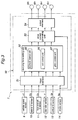
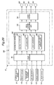
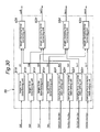
- a damping force control unit 50 is incorporated in the ECU 7 as illustrated in Figure 3 .
- the damping force control unit 50 comprises an input interface 51 to which the sensors 9 to 14 are connected, a damping force setting unit 52 for determining a target damping force of each damper 6 according to the detection signals obtained from the sensors 9 to 14, a drive current generating unit 53 for generating drive current for each damper 6 (MLV coil 42) according the corresponding target damping force supplied by the damping force setting unit 52 and a detection signal Ss from the corresponding stroke sensor 14 and an output interface 54 for supplying the drive current generated by the drive current generating unit 53 to each damper 6.
- the damping force setting unit 52 comprises a skyhook control unit 55 for performing a skyhook control, a roll control unit 56 for performing a roll control, a pitch control unit 57 for performing a pitch control, and other control units.
- the skyhook control unit 55 having the structure represented in Figure 4 is provided for each wheel.
- a skyhook control is performed by using the right front wheel as a reference wheel as will be discussed more fully hereinafter.
- the skyhook control unit 55fr corresponding to the right front wheel comprises a sprung mass speed computing unit 63fr, a skyhook control base value setting unit 61fr and a skyhook control target value computing unit 62fr.
- the sprung mass speed computing unit 63fr computes a sprung mass speed V2fr by integrating a vertical acceleration G1fr received from the vertical G sensor 13fr, and forwards it to the skyhook control base value setting unit 61fr.
- the skyhook control base value setting unit 61fr sets a skyhook control base value Dsbfr by multiplying a vehicle speed v1 received from the vehicle speed sensor 9 to the sprung mass speed V2fr received from the sprung mass speed computing unit 63fr, and multiplying a prescribed skyhook gain Gshfr to the product.
- the skyhook control target value computing unit 62fr sets a skyhook control target value Dshfr according to the skyhook control base value Dsbfr, and outputs the obtained value for a control purpose.
- the skyhook control unit 55rr for the right rear wheel comprises a sprung mass speed computing unit 63rr, a skyhook control base value setting unit 61rr, a correction value setting unit 64rr and a skyhook control target value computing unit 62rr.
- the sprung mass speed computing unit 63rr computes a sprung mass speed V2rr by integrating a vertical acceleration G1rr received from the vertical G sensor 13rr, and forwards it to the skyhook control base value setting unit 61rr.
- the skyhook control value base setting unit 61rr sets a skyhook control base value Dsbrr by multiplying a vehicle speed v1 received from the vehicle speed sensor 9 to the sprung mass speed V2rr received from the sprung mass speed computing unit 63rr, and multiplying a prescribed skyhook gain Gshrr to the product.
- a correction value setting unit 64rr computes a difference between the two sprung mass speeds V2fr and V2rr which are forwarded from the sprung mass speed computing unit 63fr and sprung mass speed computing unit 63rr, respectively, and sets a skyhook control correction value Dfrr by multiplying a prescribed correction gain Gfrr to the computed difference.
- the skyhook control target value computing unit 62rr sets a skyhook control target value Dshrr according to the skyhook control base value Dsbfr obtained from the skyhook control base value setting unit 61fr and skyhook control correction value Dfrr obtained from the skyhook control base value setting unit 61rr, and outputs the obtained value for a control purpose.
- the skyhook control unit 55fl corresponding to the left front wheel 3fl and skyhook control unit 55rl corresponding to the left rear wheel 3rl each have a structure similar to that of the skyhook control unit 55rr, and set a corresponding skyhook control target value Dshfl or Dshrl, as the case may be. It should be noted that each of the four wheels can be a reference wheel, and the foregoing description applies to each of such reference wheels.
- the damping force control unit 50 When the vehicle is traveling, the damping force control unit 50 performs a damping control represented by the flowchart of Figure 5 for each wheel at a prescribed processing interval such as 10 msec.
- the dynamic state (including at least the sprung mass speed of each wheel) of the vehicle V is determined according to the acceleration information of the vehicle obtained by the lateral G sensor 10, fore-and-aft G sensor 11 and vertical G sensors 14, the vehicle speed obtained by the vehicle speed sensor 9 and a steering speed obtained by the steering angle sensor (not shown in the drawing) in step S1.
- a skyhook control target value Dsh for each damper 6 is computed in step S2
- a roll control target value Dr for each damper 6 is computed in step S3
- a pitch control target value Dp is computed for each damper 6 in step S4.
- the damping force control unit 50 determines if the stroke speed Ss of each damper 6 is positive in step S5. If the stroke speed Ss is positive in value (or the damper 6 is extending), the largest value of the three control target values Dsh, Dr and Dp is selected as the target damping force Dtgt in step S6. If the stroke speed Ss is negative in value (or the damper 6 is contracting), the smallest value of the three control target values Dsh, Dr and Dp is selected as the target damping force Dtgt in step S7.
- step S6 the damping force control unit 50 looks up a target current Itgt corresponding to the target damping force Dtgt from a target current map as presented in the graph of Figure 6 in step S8.
- step S9 the damping force control unit 50 then supplies a drive current to the MLV coil 42 of each damper 6 according to the target current It determined in step S8
- the skyhook control unit 55 of the damping force setting unit 52 computes the skyhook control target value Sdhfr according to the procedure illustrated in the flowcharts of Figures 7 and 8 .
- the skyhook control target value Dshfr for the damper 6fr of the reference wheel or the right front wheel 3fr is computed by the corresponding skyhook control unit 55fr according to the flowchart of Figure 7
- the skyhook control target values Dshfl, Dshrr and Dshrl for the dampers 6fl, 6rr and 6rl of the remaining wheels 3fl, 3rr and 3rl are computed by the corresponding skyhook control units 55fl, 55rr and 55rl according to the flowchart of Figure 8 .
- the sprung mass speed computing unit 63fr computes the sprung mass speed v2fr by integrating the corresponding vertical acceleration G1fr in step S10.
- the skyhook control base value setting unit 61 fr then computes the skyhook control base value Dsbfr according to the vehicle speed v1, sprung mass speed v2fr and skyhook gain Gshfr in step S 11.
- the skyhook control base value setting unit 62fr outputs a skyhook control target value Dshfr according to the skyhook control base value Dsbfr.
- the sprung mass speed computing unit 63rr computes the sprung mass speed v2rr by integrating the vertical acceleration G1rr in step S13.
- the skyhook control base value setting unit 61rr then computes the skyhook control base value Dsbrr according to the vehicle speed v1, sprung mass speed v2rr and skyhook gain Gshrr in step S 14.
- the correction value setting unit 64rr computes a difference between the two sprung mass speeds V2fr and V2rr, and computes the skyhook control correction value Dfrr according to the obtained difference and the correction gain Gfrr in step S 15.
- the skyhook control target value Dshrr is computed from the skyhook control base value and skyhook control correction value Dfrr computed in steps S 14 and 15, respectively.
- the skyhook control target values Dshfl and Dshrl corresponding to the left front wheel 3fl and left rear wheel 3r1 are computed by the control flow illustrated in Figure 8 similarly as the skyhook control target value Dshrr for the right rear wheel 3rr, and is outputted for a control purpose.
- the sprung mass speeds of the different wheels can be brought to mutually similar values when performing a feedback skyhook control of the vertical movement of each wheel based on the corresponding sprung mass speed by using the right front wheel 3fr, or any other wheel, as the reference wheel for providing a correction gain for the feedback control.
- Figure 9 shows the sprung mass speeds v2 of the front wheels 3fr and 3fl and rear wheels 3rr and 3rl when the control process of the first embodiment is executed.
- the sprung mass speeds are brought close to each other, and the pitching movement of the vehicle body can be avoided.
- the sprung mass speeds v2 of the right wheels 3fr and 3rr and left wheels 3fr and 3fl may be similarly brought close to each other, and the rolling movement of the vehicle body can be avoided when the vehicle is traveling over a laterally slanted road surface.
- Figure 10 shows a block diagram of a second embodiment which is not in accordance with the present invention which is slightly modified from the first embodiment also not in accordance with the present invention.
- the parts corresponding to those of the previous embodiment are denoted with like numerals without repeating the description of such parts.
- This embodiment differs from the previous embodiment in the structures of the skyhook control units 55rr, 55fl and 55rl corresponding to the non-reference wheels, and is otherwise similar to the first embodiment.
- the skyhook control unit 55rr corresponding to the right rear wheel comprises a sprung mass speed computing unit 63rr, a feedback control target value computing unit 65rr and a skyhook control target value computing unit 62rr.
- the sprung mass speed computing unit 63rr is not different from that of the first embodiment.
- the feedback control target value computing unit 65rr computes a difference between a sprung mass speed V2fr received from the sprung mass speed computing unit 63fr and a sprung mass speed V2rr received from the sprung mass speed computing unit 63rr, and computes a feedback control target value Dfbrr according to the computed difference and a prescribed correction gain Gf2rr.
- the skyhook control target value computing unit 62rr sets a skyhook control target value Dshrr according to the feedback control target value Dfbrr, and outputs it for a control purpose.
- the skyhook control unit 55fl corresponding to the left front wheel 3fl and skyhook control unit 55rl corresponding to the left rear wheel 3rl each have a structure similar to that of the skyhook control unit 55rr, and set a corresponding skyhook control target value Dshfl or Dshrl, as the case may be.
- the sprung mass speeds of the different wheels can be brought to mutually similar values so that undesired pitching and rolling movements may be reduced by performing a feedback skyhook control of the vertical movement of each wheel based on the corresponding sprung mass speed by using the right front wheel 3fr, or any other wheel, as the reference wheel for providing a correction gain for the feedback control while doing away with the skyhook control base values for the non-reference wheels.
- FIGS 11 to 13 show a third embodiment which accords to the present invention.
- the parts corresponding to those of the previous embodiments are denoted with like numerals without repeating the description of such parts.
- the wheel suspension systems of the illustrated embodiment are configureed such that the natural frequencies Fn of the wheel suspension systems of the different wheels are identical to one another when the vehicle V is traveling over a horizontal road surface as shown in Figure 17.
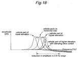
- Figure 17 , and Figures 18 and 19 which are to be discussed hereinafter, show the relationship between an amplitude ratio of the amplitude of an sprung mass movement to the amplitude of road surface irregularities and the frequency.
- the amplitude ratio is given in a logarithmic scale (20*log 10 x). Therefore, the smaller the value of the amplitude ratio is, the smaller is the amplitude of the sprung mass movement for a given input of road surface irregularities.
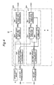
- the damping force control unit 50 is similar to that of the first embodiment, but the damping force setting unit 52 is additionally incorporated with a road inclination determining unit 58 that determines an inclination of a road surface on which the vehicle is placed or is traveling.
- the inclination of the vehicle body itself may also be used instead of the inclination of a road surface, and it should be understood that these two inclinations may be used interchangeably.
- the skyhook control unit 55 comprises a skyhook control base value setting unit 61 which sets a skyhook control base value Dsb according to a vehicle speed signal v received from the vehicle speed sensor 9 and a vertical acceleration signal G1 (sprung mass vertical acceleration) received from the vertical G sensor 13, and a skyhook control target value computing unit 62 for computing a skyhook control target value Dsh by multiplying the skyhook control base valued Dsb by a skyhook gain Gsh set by a skyhook gain setting unit 59, for each wheel.
- a skyhook control base value setting unit 61 which sets a skyhook control base value Dsb according to a vehicle speed signal v received from the vehicle speed sensor 9 and a vertical acceleration signal G1 (sprung mass vertical acceleration) received from the vertical G sensor 13, and a skyhook control target value computing unit 62 for computing a skyhook control target value Dsh by multiplying the skyhook control base valued Dsb by a skyhook gain Gsh set by a skyhook gain setting unit 59, for each wheel.
- the skyhook gain setting unit 59 comprises a wheel load computing unit 66 that computes a wheel load Le of each wheel 3 according a vehicle speed Vs received from the vehicle speed sensor 9, a stroke speed Ss received from the stroke sensor 14 and a yaw rate ⁇ received from the yaw rate sensor 12, a natural frequency computing unit 67 that computes a natural frequency Fn of the part of the vehicle body adjacent to the corresponding wheel 3 according to the wheel load Le, and a control gain setting unit 68 that sets the skyhook gain Gsh according to the output of the natural frequency computing unit 67.
- the road inclination determining unit 58 is configured to determine a fore-and-aft inclination ⁇ x of the road surface in a fore-and-aft direction of the vehicle according to a fore-and-aft acceleration Gx received from the fore-and-aft G sensor 11 when the vehicle is traveling at a constant speed as detected by the vehicle speed sensor 9, and a lateral inclination ⁇ y of the road surface in a lateral direction of the vehicle according to a lateral acceleration Gy received from the lateral G sensor 10 when a yaw rate ⁇ received from the yaw rate sensor 12 is zero.
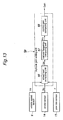
- the damping force control unit 50 When the vehicle is traveling, the damping force control unit 50 performs a damping control represented by the flowchart of Figure 14 for each wheel at a prescribed processing interval such as 10 msec.
- the road inclination determining unit 58 of the damping force setting unit 52 determines inclinations of the road surface ⁇ x and ⁇ y in step S21. If any appreciable inclination in any direction is not detected (No) in step S21, the skyhook control unit 55 of the damping force setting unit 52 executes an attitude change reduction control which will be described hereinafter in step S24. In this attitude change reduction control, a skyhook control target value Dsh or a target damping force for each damper 6 is determined.
- step S21 if an appreciable inclination in any direction is detected (Yes) in step S21, it is determined if the detected inclination angle is greater than a prescribed value in step S22. If the detected inclination angle is greater than the prescribed value (No) in step S22, the attitude change reduction control is executed in step S24. If the detected inclination angle is smaller than the prescribed value (Yes) in step S22, the skyhook control unit 55 of the damping force setting unit 52 executes a inclined road vibration reduction control in step S23 which will be described hereinafter. In this inclined road vibration reduction control, a skyhook control target value Dsh or a target damping force for each damper 6 is determined similarly as in the attitude change reduction control.
- the drive current generating unit 53 of the damping force control unit 50 determines a target drive current for each target damping force given by the attitude change reduction control or inclined road vibration reduction control by looking up a prescribed target current map in step S25, and supplies a corresponding electric current to the MLV coil 42 of each damper 6 in step S26. The foregoing steps are repeated thereafter.
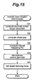
- the skyhook control base value setting unit 61 of the damping force setting unit 52 determines a skyhook control base value Dsb in step S31.
- the wheel load computing unit 66 of the skyhook gain setting unit 59 computes a wheel load Le of each wheel in step S32, and the natural frequency computing unit 67 computes a natural frequency Fn of the corresponding part of the vehicle body according to the wheel load Le computed in step S32 (step S33), and the control gain setting unit 68 determines a skyhook gain Gsh for each wheel 3 according to the natural frequency Fn computed in step S33 (step S34).
- the skyhook gain Gsh of the vehicle part located at a higher elevation in the inclination determined by the road inclination determining unit 58 is corrected such that a smaller resonant amplitude may be attained
- the skyhook gain Gsh of the vehicle part located at a lower elevation in the inclination determined by the road inclination determining unit 58 is corrected such that a larger resonant amplitude may be attained.
- the skyhook control target value computing unit 62 of the damping force setting unit 52 computes a skyhook control target value Dsh for each damper 6 by multiplying the natural frequency Fn to the skyhook control base value Dsb set in step S31 (step S35). This concludes the inclined road vibration reduction control process.
- the skyhook control unit 55 of the damping force setting unit 52 determines a dynamic state (such as a sprung mass speed of each wheel 3) according to the acceleration information of the vehicle V obtained from the lateral G sensor 10, fore-and-aft G sensor 11 and vertical G sensor 13, vehicle speed obtained from the vehicle speed sensor 9 and a steering speed obtained from a steering angle sensor not shown in the drawings (step S41).
- the skyhook control unit 55 of the damping force setting unit 52 then computes a skyhook control target value Dsh for each damper 6 according to the dynamic state of the vehicle V determined in step S41 (step S42).
- the roll control unit 57 computes a roll control target value Dr for each damper in step S43
- the pitch control unit 58 computes a pitch control target value Dp for each damper in step S44 in a similar fashion.
- the damping force setting unit 52 sets the computed skyhook control target value Dsh in step S45, and this concludes the attitude change reduction control process.
- the wheel suspension systems are configured such that the natural frequencies of the all the wheel suspension systems are identical to one another when the vehicle is traveling over a horizontal road surface. However, as discussed above, when the vehicle is traveling over a slanted road surface, the wheel load acting on a wheel at a higher elevation is smaller than that acting on a wheel at a lower elevation.
- the skyhook gains Gsh are adjusted such that the resonant oscillation amplitude of the wheel at the higher elevation which is associated with a higher natural frequency is reduced so that the oscillation of the sprung mass in a frequency range of 2 to 8 Hz (which is known to be important for the ride quality of the vehicle) can be reduced, and the rider quality when traveling over a slanted road surface can be improved.
- the skyhook control is enabled to improve the ride quality of the vehicle when the vehicle is traveling over a slanted road surface.
- the inclined road vibration reduction control When there is substantially no slanting in the road surface, the inclined road vibration reduction control is not necessary, and the normal attitude change reduction control is selected. Also when the slanting of the road surface is greater than a threshold level, the difference between the natural frequencies of the vehicle parts associated with the wheels at higher and lower elevations is so great that the inclined road vibration reduction control is ineffective, and the normal attitude change reduction control is selected. When the slanting of the road surface is in a certain small range below this threshold level, the inclined road vibration reduction control is selected as it is effective in controlling the vertical vibrations of the vehicle.
- Figures 20 and 21 show a fourth embodiment of the present invention.
- the parts corresponding to those of the previous embodiments are denoted with like numerals without repeating the description of such parts.
- the damping force setting unit 52 comprises a skyhook control unit 55, a roll control unit 56 and a pitch control unit 57.
- the roll control unit 56 and pitch control unit 57 are configured to control the rolling movement of the vehicle such as when the vehicle is making a turn and the pitching movement of the vehicle such as when the vehicle is accelerating or decelerating, and thereby jointly control the attitude of the vehicle.
- the skyhook control unit 55 controls the vertical movement of the vehicle to improve the ride quality such as when the vehicle rides over road surface irregularities.
- the roll control unit 56 comprises a pair of low pass filters 71 and 72, a differentiator 73, a second order differentiator 74, a yaw rate gain multiplier 75, an adder 76, a lateral acceleration gain multiplier 77, a vehicle speed map 78, a sign detector 79 and a push-pull gain multiplier 80. These components are used for computing a target damping force for each damper at a prescribed timing.
- the low pass filter 71 removes lateral acceleration components, that are produced for causes other than a steering action when the vehicle is traveling, from the lateral acceleration Gy detected by the lateral G sensor 10, and this filtered signal is converted into a differential value dGy/dt of the lateral acceleration by the differentiator 73.
- the other low pass filter 72 removes yaw rate components, that are produced for causes other than a steering action when the vehicle is traveling, from the yaw rate ⁇ detected by the yaw rate sensor 72, and this filtered signal is converted into a second-order differential value d 2 ⁇ /dt 2 of the yaw rate ⁇ by the second-order differentiator 74.
- the second-order differential value d 2 ⁇ /dt 2 of the yaw rate ⁇ is forwarded to the yaw rate gain multiplier 75 which multiplies the distances Lf and Lr (See Figure 1 ) from the gravitational center to the front axle and rear axle, respectively, to the second-order differential value d 2 ⁇ /dt 2 to obtain correction values d 2 ⁇ /dt 2 ⁇ Lf and d 2 ⁇ /dt 2 ⁇ Lr for the lateral acceleration differential values (dGy/dt) F and (dGy/dt) R for the positions of the front wheels 3fl and 3fr and rear wheels 3rl and 3rr, respectively, as the vehicle undergoes a yaw movement.
- the lateral acceleration differential value (dGy/dt) F for the front wheels and the correction value d 2 y/dt 2 ⁇ Lf for the lateral acceleration differential value for the front wheels are forwarded to the adder 76 to obtain a corrected lateral acceleration differential value (dGy/dt) F + d2 ⁇ /dt 2 ⁇ Lf for the front wheels.
- the lateral acceleration differential value (dGy/dt) R for the rear wheels and the correction value d 2 ⁇ /dt 2 ⁇ Lr for the lateral acceleration differential value for the rear wheels are forwarded to the adder 76 to obtain a corrected lateral acceleration differential value (dG ⁇ /dt) R + d 2 ⁇ /dt 2 ⁇ Lr for the rear wheels.
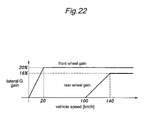
- lateral acceleration gains for the front wheel side and rear wheel side are obtained from the vehicle speed v detected by the vehicle speed sensor 9 by using the vehicle speed map 78 which is represented in the graph of Figure 22 , and are multiplied by the corrected lateral acceleration differential values for the front wheels and rear wheels (that were computed by the adder 76) at the lateral acceleration gain multiplier 77.
- the signs of the lateral accelerations for the front wheel side and rear wheel side are determined by the sign detector 79.
- a push-pull gain that depends on if the suspension is contracting or extending according to the lateral acceleration acting upon the vehicle body is multiplied to the output of the lateral acceleration gain multiplier 77 at the push-pull gain multiplier 80.
- the skyhook control unit 55 and pitch control unit 57 compute corresponding target damping forces.
- the largest of the three corresponding target damping forces is selected as the final target damping force.
- the smallest of the three corresponding target damping forces is selected as the final target damping force.
- the drive current setting unit 53 determines a target electric current according to the target damping force and a stroke speed obtained from the stroke sensor 14 by looking up a target current map shown in Figure 6 .
- the electric current supplied to the MLV coil 42 of each damper 4 is feedback controlled based on the determined target electric current.
- the damping force setting unit 52 is configured such that an increase in the damping force occurs earlier on the side of the front wheels 3fl and 3fr than on the side of the rear wheel 3rl and 3rr by increasing the gain for the front wheels 3fl and 3fr earlier than the gain for the rear wheels 3rl and 3rr.
- the ECU 7 is provided with a turning condition determining unit 70 which determines a turning condition of the vehicle according to the lateral acceleration detected by the lateral G sensor 10.
- the turning condition determining unit 70 not only detects if the vehicle is turning or not from the lateral acceleration detected by the lateral G sensor 10 but also determines which of the wheels are inside of the curve according to the direction of the lateral acceleration.
- the drive current setting unit 53 is incorporated with a delay processing unit 53a which provides a delay in the supply of drive current to the dampers 4 on the inside of the curve.
- the drive current setting unit 53 delays the rise in the drive current for the damper 4 corresponding to the front wheel which is inside of the curve as determined by the turning condition determining unit 70, and the timing of providing a damping force for the inner one of the front wheels 3fl and 3fr is delayed with respect to that for the outer front wheel.
- the drive current setting unit 53 delays the rise in the drive current for the damper 4 corresponding to the rear wheel which is inside of the curve as determined by the turning condition determining unit 70, and the timing of providing a damping force for the inner one of the rear wheels 3fl and 3fr is delayed with respect to that for the outer rear wheel.
- Figures 23 and 24 illustrate the cornering forces of the vehicle as it makes a turn, and the modes of generating damping forces at such times.
- Figure 23 shows the case where the delay control is performed on the front wheels
- Figure 24 shows the case where the delay control is performed on the rear wheels.
- the vehicle is assumed to be making a left turn.
- the delay control process may be performed only on the front wheels or on the rear wheels, or on both the front and rear wheels depending on the desired property of the vehicle handling.
- Figure 25 is a graph showing results of simulations that represent the changes in the yaw acceleration when a delay control is applied to the front wheels and rear wheels, respectively.
- the damping force for the front wheels is increased before the damping force for the rear wheels is increased as illustrated in Figure 23A .
- the driving stability of the vehicle can be thus improved by increasing the gain for the front wheels before the gain for the rear wheels is creased so that the damping force for the front wheels rises earlier than that for the rear wheels when performing a roll movement control owing to the fact that the front wheels that are steered experience a yaw movement before the rear wheels do.
- the dynamic properties such as steer feel and driving stability can be adjusted at will.
- Figure 25 shows examples of different vehicle body weight ratios, and it can be seen that the vehicle body weight ratio does not substantially affect the properties in the changes of the yaw angle acceleration when a delayed control is performed on the inner front and inner rear wheels.
- FIG. 26 is a block diagram of a fifth embodiment of the present invention which differs from the previous embodiment in that the delay process is executed within the roll control unit 56.
- the turning condition determining unit 70 is provided in a different part of the system (in the roll control unit 56), and the drive current setting unit 53 is not provided with the delay processing unit 53a.
- the roll control unit 56 is provided with a turning condition determining unit 82 for determining the turning condition of the vehicle.
- the turning condition determining unit 82 not only determines if the vehicle is turning or not from the lateral acceleration but also forwards the gains for the inner wheels and outer wheels to a corresponding delay processing multiplier 83, which is incorporated in an output end of the roll control unit 56, depending on the direction (or sign) of the determined turning movement
- the gains for the inner and outer wheels are controlled such that the timing for generating the damping force for the inner front wheel is delayed with respect to the outer front wheel.
- the delay control is performed in such a manner that the delay processing multiplier 83 multiplies the gains for the inner and outer wheels to the target damping forces for the front and rear wheels which are forwarded from the push-pull gain multiplier 80.
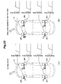
- Figures 27A and 27B are schematic views showing the changes in the wheel loads of the inner and outer, front and rear wheels when the delay control is applied to the inner front wheel.
- the vehicle turns to the left in Figure 27 , and a right turn of the vehicle gives rises to a mirror image of this drawing.
- the resulting inertia force of the vehicle body 1 causes the sum of the wheel loads of the inner and outer wheels to be greater than the static value thereof so that the wheel load change of the outer wheel (which is same in sense to the inertia force) is increased by the contribution of the inertia force while the wheel load change of the inner wheel (which is opposite in sense to the inertia force) is decreased by the contribution of the inertia force
- Figure 28A is a graph showing the change in the wheel loads of the front and rear wheels immediately after a steering action
- Figure 28B is a diagram showing the mode of change in the wheel loads of the front and rear wheels.
- I yaw inertia moment
- ⁇ yaw rate
- Lf and Lr are distances of the front and rear axles from the gravitational center
- Yfl, Yfr, Yrl and Yrr are cornering forces of the corresponding wheels.
- Figure 29 shows a sixth embodiment which is not in accordance with the present invention in which the damping force setting unit 52 is similar to that of the first embodiment also not in accordance with the present invention, but additionally includes a sprung mass speed estimating unit 60 which estimates a sprung mass speed associated with each wheel.
- FIG 30 is a block diagram representing the structure of the skyhook control unit 55 in a simplified manner.
- the skyhook control unit 55 comprises, for each wheel 3fl - 3rr, a target damping force setting unit 91fl-91rr, a damping force correction value setting unit 92fl - 92rr and a target damping force correcting unit 93fl - 93rr.
- Each target damping force setting unit 91 sets a corresponding target damping force according to a vertical acceleration Gz detected by the vertical G sensor 13 provided adjacent to the corresponding wheel by using a single wheel oscillation model that takes into account the operating properties of the wheel suspension system.
- the damping force correction value setting unit 92 sets a corresponding damping force correction value Dc by taking into account a vertical acceleration Gz or sprung mass speed associated with at least one of the remaining or other wheels so as to appropriately distribute the damping force among the different dampers as will be described in greater detail in the following.
- the target damping force correcting unit 93 corrects the corresponding target damping force Dt according to the corresponding damping force correction value.
- the damping force control unit 50 When the vehicle is traveling, the damping force control unit 50 performs a damping control represented by the flowchart of Figure 31 for each wheel at a prescribed processing interval such as 10 msec.
- the dynamic state of the vehicle V is determined according to the acceleration information of the vehicle 13, obtained by the lateral G sensor 10, fore-and-aft G sensor 11 and vertical G sensors 13, the vehicle speed obtained by the vehicle speed sensor 9 and a steering speed obtained by the steering angle sensor (not shown in the drawing) in step S51.
- a skyhook control target value Dsh for each damper 6 is computed in step S52
- a roll control target value Dr for each damper 6 is computed in step S53
- a pitch control target value Dp is computed for each damper 6 is computed in step S54.
- the damping force control unit 50 determines if the stroke speed Ss of each damper 6 is positive in sign in step S55. If the determination result is Yes or the damper is extending, the greater of the three control target values Dsh, Dr and Dp is set as the target damping force Dtgt in step S56. Conversely, if the determination result is No or the damper is contracting, the smallest of the three control target values Dsh, Dr and Dp is set as the target damping force Dtgt in step S57.
- the damping force control unit 50 looks up a target current Itgt corresponding to the target damping force Dtgt from a target current map as presented in the graph of Figure 6 in step S58. In step S59, the damping force control unit 50 then supplies a drive current to the MLV coil 42 of each damper 6 according to the target current It determined in step S58.
- the skyhook control process is now described in the following with reference to Figure 32 .
- the skyhook control unit 55 performs a similar skyhook control process on each of the dampers 6 for the different wheels 3, but only the control process for the left front wheel 3fl is described in the following to simplify the description and avoid redundancy.
- Figure 32 is a flowchart of a first example of the skyhook control process.
- the skyhook control unit 55 computes the vertical speeds Vzfl, Vzfr, Vzrl and Vzrr (sprung mass speeds) according to the integrated values of the vertical accelerations Gzfl, Gzfr, Gzrl and Gzrr of the damper bases 1a of the corresponding wheels 3 in step S61.
- the target damping force setting unit 91fl sets a target damping force Dtfl according to the vertical speed Vzfl of the damper base 1afl by looking up a prescribed map in step S62.
- the damping force correction value setting unit 92fl computes an average Vza of the vertical speeds Vzfr, Vzrl and Vzrr of the remaining damper bases 1a in step S63, and a damping force correction value Dcfl is determined from the average value Vza by looking up a prescribed map in step S64.
- the target damping force correcting unit 63fl determines if the input to the left front damper base 1afl is in the same phase as the input to the remaining damper bases 1afr, 1arl and 1arr or if the vertical speed Vzfl is the same in sign as the average value Vza according to the following formula in step S65.
- the target damping force correcting unit 63fl computes a skyhook control target value Dshfl from the target damping force Dtfl according to the following formula in step S66.
- Dshfl K ⁇ 1 ⁇ Dtfl where K1 is a coefficient.
- the target damping force correcting unit 63fl computes a skyhook control target value Dshfl from the target damping force Dtfl and damping force correcting value Dcfl according to the following formula in step S67.
- Dshfl K ⁇ 1 ⁇ Dtfl - K ⁇ 2 ⁇ Dcfl where K2 is a coefficient.
- the skyhook control target value Dshfl is forwarded to the damping force setting unit 52 in step S68, and this concludes the skyhook control process.
- the damping force correction value for the left front damper 6fl was determined according to the average value of the vertical speeds of the damper bases associated with the dampers which are longitudinally, laterally and diagonally adjacent to the left front damper 6fl.
- the skyhook control target value Dshfl is selected so as to have an absolute value greater than that of the target damping force (more conventional target damping force) Dtcfl by subtracting the damping force correcting value Dcfl from the target damping force Dtcfl. Therefore, the change in the attitude of the vehicle can be controlled in an effective manner.
- the skyhook control target value Dshfl for the damper 6fl is determined without being affected by the vertical speeds of the remaining three damper bases 1a.
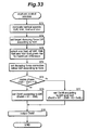
- FIG 33 is a flowchart of a second example of the skyhook control process. Parts of the description of this example common to those of the first example are omitted in the following description to avoid redundancy.
- the skyhook control unit 55 computes the vertical speeds Vzfl, Vzfr, Vzrl and Vzrr in a similar fashion in step S71.
- the target damping force setting unit 91fl then sets a target damping force Dtfl according to the vertical speed Vzfl of the damper base lafl by looking up a prescribed map in step S72.
- the damping force correction value setting unit 92fl selects one of the vertical speeds of the front right, rear left and rear right damper bases 1a whose vertical speed has the greatest difference from the vertical distance Vzfl as the maximum value Vzm in step S73.
- a damping force correction value Dcfl is determined from the maximum value Vzm by looking up a prescribed map in step S74.
- the target damping force correcting unit 63fl determines if the input to the left front damper base 1afl is in the same phase as the input to the damper base associated with the maximum value Vzm of the vertical speeds or if the vertical speed Vzfl is the same in sign as the maximum value Vzm according to the following formula in step S75.
- the target damping force correcting unit 63fl computes a skyhook control target value Dshfl from the target damping force Dtfl according to the following formula in step S76.
- Dshfl K ⁇ 1 ⁇ Dtfl where K1 is a coefficient.
- the target damping force correcting unit 63fl computes a skyhook control target value Dshfl from the target damping force Dtfl and damping force correcting value Dcfl according to the following formula in step S77.
- Dshfl K ⁇ 1 ⁇ Dtfl - K ⁇ 2 ⁇ Dcfl where K2 is a coefficient.
- the skyhook control target value Dshfl is forwarded to the damping force setting unit 52 in step S78, and this concludes the skyhook control process.
- the damping force correction value for the left front damper 6fl is determined from one (the maximum value Vzm) of the vertical speeds of the front right, rear left and rear right damper bases 1a whose vertical speed has the greatest difference from the vertical speed Vzfl associated with the wheel 3fl which is being controlled.
- the skyhook control target value Dshfl is selected so as to have an absolute value greater than that of the target damping force (more conventional target damping force) Dtcfl by subtracting the damping force correcting value Dcfl based on the vertical speed which is most different from the vertical speed of the front left damper base 1a from the target damping force Dtcfl. Therefore, the change in the attitude of the vehicle can be controlled in an effective manner.
- the skyhook control target value Dshfl for the damper 6fl is determined without being affected by the vertical speeds of the remaining three damper bases 1a. Also, this is effected without unduly increasing the damping force of the front left damper so that the attitude change of the vehicle can be favorably controlled.
- Figure 34 is a flowchart of a third example of the skyhook control process.
- the skyhook control unit 55 computes the vertical speeds Vzfl, Vzfr, Vzrl and Vzrr according to the integrated values of the vertical accelerations Gzfl, Gzfr, Gzrl and Gzrr of the damper bases 1a of the corresponding wheels 3 in step S81.
- the target damping force setting unit 91fl sets a target damping force Dtfl according to the vertical speed Vzfl of the damper base 1afl by looking up a prescribed map in step S82.
- the damping force correction value setting unit 92fl computes a front average value Vzfa from the vertical speeds Vzfl and Vzfr of the right and left front damper bases 1afl and 1afr and a rear average value Vzra from the vertical speeds Vzrl and Vzrr of the right and left rear damper bases 1arl and 1arr by using the following formulas in step S83.
- Vzfa Vzfl + Vzfr / 2 > 0
- Vzra Vzrl + Vzrr / 2 > 0
- the damping force correction value setting unit 92fl determines a damping force correction value Dcfl from the rear average value Vzra by looking up a prescribed map in step S84.
- the target damping force correcting unit 93fl determines if the input to the front part (damper bases 1aft and 1afr) of the vehicle body is in the same phase as the input to the rear part (damper bases 1arl and 1arr) of the vehicle body, or if the front average value (of the vertical speeds Vzfl and Vzfr) is the same in sign as the rear average value Vza (of the vertical speeds Vzrl and Vzrr) according to the following formula in step S85.
- the target damping force correcting unit 93fl computes a skyhook control target value Dshfl from the target damping force Dtfl according to the following formula in step S86.
- Dshfl K ⁇ 1 ⁇ Dtfl where K1 is a coefficient.
- the target damping force correcting unit 93fl computes a skyhook control target value Dshfl from the target damping force Dtfl and damping force correcting value Dcfl according to the following formula in step S87.
- Dshfl K ⁇ 1 ⁇ Dtfl - K ⁇ 2 ⁇ Dcfl where K2 is a coefficient.
- the skyhook control target value Dshfl is forwarded to the damping force setting unit 52 in step S88, and this concludes the skyhook control process.
- the damping force correction value for the left front damper 6fl was determined according to the rear average value of the vertical speeds of the damper bases associated the right and left rear wheels.
- the pitch changes of the vehicle V is significant, and the skyhook control target value Dshfl is selected so as to have an absolute value greater than that of the target damping force (more conventional target damping force) Dtcfl by subtracting the damping force correcting value Dcfl from the target damping force Dtcfl. Therefore, the change in the pitch changes of the vehicle can be controlled in an effective manner.
- the skyhook control target value Dshfl for the damper 6fl is determined without being affected by the rear average value of the vertical speeds of the rear damper bases (or without excessively increasing the damping force), and the pitch movements of the vehicle V can be controlled in an appropriate manner.
- FIG 35 is a flowchart of a fourth example of the skyhook control process.
- the skyhook control unit 55 computes the left vertical speeds Vzfl and Vzrl according to the integrated values of the vertical accelerations Gzfl and Gzrl of the damper bases 1a of the left wheels 3fl and 3rl in step S91.
- the target damping force setting unit 91fl sets a target damping force Dtfl according to the vertical speed Vzfl of the damper base 1afl corresponding to the left front wheel 3fl by looking up a prescribed map in step S92.
- the damping force correction value setting unit 92fl computes a damping force correction value Dcfl from the vertical speed Vzrl of the damper base 1arl corresponding to the left rear wheel 3rl by looking up a prescribed map in step S93.
- the target damping force correcting unit 93fl determines if the input to the left front damper base 1afl is in the same phase as the input to the left rear damper base 1arl or if the vertical speed Vzfl is the same in sign as the vertical speed Vzrl according to the following formula in step S94. Vzfl ⁇ Vzrl > 0
- the target damping force correcting unit 93fl computes a skyhook control target value Dshfl from the target damping force Dtfl according to the following formula in step S95.
- Dshfl K ⁇ 1 ⁇ Dtfl where K1 is a coefficient.
- the target damping force correcting unit 93fl computes a skyhook control target value Dshfl from the target damping force Dtfl and damping force correcting value Dcfl according to the following formula in step S96.
- Dshfl K ⁇ 1 ⁇ Dtfl - K ⁇ 2 ⁇ Dcfl where K2 is a coefficient.
- the skyhook control target value Dshfl is forwarded to the damping force setting unit 52 in step S97, and this concludes the skyhook control process.
- the damping force correction value Dcfl for the left front damper 6fl is determined according to the input (vertical speed Vzrl) to the left rear damper base 1arl.
- the skyhook control target value Dshfl is selected so as to have an absolute value greater than that of the target damping force (more conventional target damping force) Dtcfl by subtracting the damping force correcting value Dcfl from the target damping force Dtcfl. Therefore, the change in the pitch change of the vehicle can be controlled in an effective manner.
- the skyhook control target value Dshfl for the damper 6fl is determined without being affected by the vertical speed Vzrl of the left rear damper base 1arl or without generating an excessive damping force. Therefore, the pitching movement of the vehicle V can be controlled in an appropriate manner.
- the damping force correction value Dc was selected according to the vertical speed Vz of the front or rear damper base 1a which is on the same side of the vehicle body as the damper which is to be controlled.
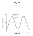
- the abscissa (time) of the graph is shifted for each curve so that the curves may be more easily compared with one another.
- the examples 3 and 4 achieve a significant reduction in the pitching rate of the vehicle body 1 when the vehicle is subjected to opposite phase inputs as compared with the prior art.
- FIG 37 is a flowchart of a fifth example of the skyhook control process.
- the skyhook control unit 55 computes the front vertical speeds Vzfl and Vzfr according to the integrated values of the vertical accelerations Gzfl and Gzfr of the damper bases 1a of the front wheels 3fl and 3fr in step S101.
- the target damping force setting unit 91fl then sets a target damping force Dtfl according to the vertical speed Vzfl of the damper base 1afl by looking up a prescribed map in step S102.
- the damping force correction value setting unit 92fl for the left front wheel 3fl computes a damping force correction value Dcfl from the vertical speed Vzfr associated with the right front wheel 3fr by looking up a prescribed map in step S 103.
- the target damping force correcting unit 93fl determines if the input to the left front damper base 1afl is in the same phase as the input to the right front damper base 1afr or if the vertical speed Vzfl is the same in sign with the vertical speed Vzfr according to the following formula in step S104. Vzfl ⁇ Vzfr > 0
- step S 104 If the determination result is Yes in step S 104 or the input to the left front damper base 1afl is in the same phase as that of the right front damper base 1afr, the target damping force correcting unit 93fl computes a skyhook control target value Dshfl from the target damping force Dtfl according to the following formula in step S105.
- Dshfl K ⁇ 1 ⁇ Dtfl where K1 is a coefficient.
- the target damping force correcting unit 93fl computes a skyhook control target value Dshfl from the target damping force Dtfl and damping force correcting value Dcfl according to the following formula in step S106.
- Dshfl K ⁇ 1 ⁇ Dtfl - K ⁇ 2 ⁇ Dcfl where K2 is a coefficient.
- the skyhook control target value Dshfl is forwarded to the damping force setting unit 52 in step S107, and this concludes the skyhook control process.
- the damping force correction value Dcfl for the left front damper 6fl is determined according to the input (vertical speed Vzrl) to the right front damper base 1afr.
- the skyhook control target value Dshfl is selected so as to have an absolute value greater than that of the target damping force (more conventional target damping force) Dtcfl by subtracting the damping force correcting value from the target damping force Dtcfl. Therefore, the change in the roll movement of the vehicle can be controlled in an effective manner.
- the skyhook control target value Dshfl for the damper 6fl is determined without being affected by the vertical speed Vzfr of the front right damper base 1afr or without generating an excessive damping force. Therefore, the rolling movement of the vehicle V can be controlled in an appropriate manner.
- FIG 39 is a flowchart of a sixth example of the skyhook control process.
- the skyhook control unit 55 computes the vertical speeds Vzfl and Vzrr according to the integrated values of the vertical accelerations Gzfl and Gzrr of the damper bases 1a of the left front wheel 3fl and right rear wheel 3rr (which is diagonally opposite to the left front wheel 3fl) in step S111.
- the target damping force setting unit 91fl sets a target damping force Dtfl according to the vertical speed Vzfl of the damper base 1afl by looking up a prescribed map in step S112.
- the damping force correction value setting unit 92fl computes a damping force correction value Dcfl is determined from the vertical speed Vzrr associated with the right rear wheel 3rr by looking up a prescribed map in step S 113.
- the target damping force correcting unit 93fl determines if the input to the left front damper base 1afl is in the same phase as the input to the (diagonally opposite) right rear damper base 1arr or if the vertical speed Vzfl is the same in sign with the vertical speed Vzrr according to the following formula in step S114. Vzfl ⁇ Vzrr > 0
- step S 114 If the determination result is Yes in step S 114 or the input to the left front damper base 1afl is in the same phase as that of the right rear damper base 1arr, the target damping force correcting unit 93fl computes a skyhook control target value Dshfl from the target damping force Dtfl according to the following formula in step S115.
- Dshfl K ⁇ 1 ⁇ Dtfl where K1 is a coefficient.
- the target damping force correcting unit 93fl computes a skyhook control target value Dshfl from the target damping force Dtfl and damping force correcting value Dcfl according to the following formula in step S116.
- Dshfl K ⁇ 1 ⁇ Dtfl - K ⁇ 2 ⁇ Dcfl where K2 is a coefficient.
- the skyhook control target value Dshfl is forwarded to the damping force setting unit 52 in step S117, and this concludes the skyhook control process.
- the damping force correction value Dcfl for the left front damper 6fl is determined according to the input (vertical speed Vzrr) to the right rear damper base 1arr.
- the skyhook control target value Dshfl is selected so as to have an absolute value greater than that of the target damping force (more conventional target damping force) Dtcfl by subtracting the damping force correcting value from the target damping force Dtcfl. Therefore, the change in the roll and pitch movements of the vehicle can be controlled in an effective manner.
- the skyhook control target value Dshfl for the damper 6fl is determined without being affected by the vertical speed Vzrr of the rear right damper base 1arr or without generating an excessive damping force. Therefore, the rolling and pitching movements of the vehicle V can be controlled in an appropriate manner.
- the damping force correction value Dc was selected according to the vertical speed Vz of the damper base 1a which is diagonally opposite to the damper which is to be controlled. As can be appreciated from the graphs of Figures 40 and 41 , the sixth example achieves a significant reduction in the rolling rate and pitching rate of the vehicle body 1 when the vehicle is subjected to opposite phase inputs as compared with the prior art.
- a seventh embodiment of the present invention is described in the following with reference to Figures 42 to 46 .
- the parts corresponding to those of the previous embodiments are denoted with like numerals without repeating the description of such parts.
- each wheel is supported by a wheel suspension system 107 using an air spring 105 instead of a more conventional coil spring.
- the wheel suspension systems are configured such that the natural frequencies of the vertical movements of the wheel are identical to one another when the vehicle is traveling over a horizontal road surface.
- the air spring 105 used in the present embodiment is provided with a per se known structure, and the detailed description thereof is omitted in this specification. It includes a tubular air piston surrounding the cylinder 22 of the damper 6, a tubular air cylinder connected to the piston rod 23 of the damper 6 and having a larger diameter than the air piston, a flexible diaphragm connected to both the air piston and air cylinder so as to accommodate a relative axial movement between the air piston and air cylinder and a tubular cover connected to the lower end of the air chamber and receiving the diaphragm therein.
- An air chamber defined by the air piston, air cylinder and diaphragm communicates with an air tube whose other end is connected to an air compressor or an air tank.
- the suspension property control unit 150 comprises an input interface 51 to which the sensors 9 to 14 are connected, a damping force setting unit 52 for determining the target damping force of each damper 6 according to the detection signals obtained from the sensors 9 to 14, a spring constant control unit 101 for setting a spring constant control value Dsu of each air spring according to the detection signals obtained from the sensors 9 to 14, a spring drive current generating unit 102 for generating a drive current for the air compressor or pressure control valve corresponding to each air spring 105 according to the spring constant control value Dsu received from the spring constant control unit 101, a damper drive current generating unit 53 for generating the drive current for each damper 6 (MLV coil 42) according the corresponding target damping force supplied by the damping force setting unit 52 and an output interface 54 for supplying the drive currents generated by the damper drive current generating unit 53 and spring drive current generating unit 102 to each damper 6 and each air spring 105, respectively.
- a damping force setting unit 52 for determining the target damping force of each damper 6 according
- the spring constant control unit 101 is provided for each wheel, and the spring constant control is executed using the right front wheel as a reference wheel in the illustrated embodiment.
- the reference wheel may also be any other wheel according to a broad concept of the present invention.
- the spring constant control unit 101 variably controls (feedback control) the spring constants of the air springs 105 such that the natural frequency Fn of the part of the vehicle body corresponding to each non-reference wheel that can vary depending on the corresponding wheel load Le is equal to or substantially equal to the natural frequency Fnfr of the part of the vehicle body corresponding to the reference wheel or right front wheel 3fr.
- the spring constant control unit 101fr corresponding to the right front wheel (reference wheel) 3fr comprises a wheel load computing unit 102fr, a natural frequency computing unit 103fr and a spring constant control target value computing unit 104fr.
- the wheel load computing unit 102fr computes the wheel load Lefr of the right front wheel 3fr according to the vehicle speed v1 received from the vehicle speed sensor 9, a stroke speed Ssfr received from the stroke sensor 14fr corresponding to the right front wheel 3fr and a yaw rate ⁇ received from the yaw rate sensor 12.
- the natural frequency computing unit 103fr computes the natural frequency Fnfr of the part of the vehicle body corresponding to the right front wheel 3fr according to the wheel load Lefr.
- the spring constant control target value computing unit 104fr sets a spring constant control target value Dsufr according to the computed natural frequency Fnfr, and outputs it for a control purpose.
- the spring constant control unit 101rr corresponding to the right rear wheel 3rr comprises a wheel load computing unit 102rr, a natural frequency computing unit 103rr and a spring constant control target value computing unit 104rr.
- the wheel load computing unit 102rr computes the wheel load Lerr of the right rear wheel 3rr according to the vehicle speed v1 received from the vehicle speed sensor 9, a stroke speed Ssrr received from the stroke sensor 14rr corresponding to the right rear wheel 3rr and a yaw rate ⁇ received from the yaw rate sensor 12.
- the natural frequency computing unit 103rr computes the natural frequency Fnrr of the part of the vehicle body corresponding to the right rear wheel 3rr according to the wheel load Lerr.
- the spring constant control target value computing unit 104rr sets a spring constant control target value Dsurr according to the wheel load Lerr so as to minimize a difference ⁇ Fnrr between the natural frequency of the part of the vehicle body corresponding to the right front wheel 3fr and natural frequency of the part of the vehicle body corresponding to the right rear wheel 3rr.
- the spring constant control unit 101fl corresponding to the left front wheel 3fl and spring constant control unit 101rl corresponding to the left rear wheel 3rl are each provided with a structure similar to that of the spring constant control unit 101rr corresponding to the right rear wheel 3rr, and compute a spring constant control target value Dsufl or Dsurl according to the wheel load Lefl or Lerl so as to minimize a difference ⁇ Fnfl and ⁇ Fnrl between the natural frequency of the part of the vehicle body corresponding to the right front wheel (reference wheel) 3fr and natural frequency Fnfl or Fnrl of the part of the vehicle body corresponding to the left front wheel 3fl or left rear wheel 3r1, as the case may be.
- the spring constant control unit 101 of the suspension property control unit 150 computes the spring constant control target value Dsu according to the control process illustrated in Figures 45 and 46 .
- the spring constant control target value Dsufr for the air spring 105fr of the right front wheel 3fr or the reference wheel is computed by the spring constant control unit 101fr according to the flowchart of Figure 45
- the spring constant control target values Dsufl, Dsurr and Dsurl of the air springs 1053fl, 105rr and 105rl of the remaining wheels 3f1, 3rr and 3r1 are computed by the spring constant control units 101fl, 101rr and 101rl according to the flowchart of Figure 46 .
- the wheel load computing unit 102fr computes the wheel load Lefr corresponding to the right front wheel 3fr according to the vehicle speed v1, a stroke speed Ssfr corresponding to the right front wheel 3fr and a yaw rate ⁇ in step S121.
- the natural frequency computing unit 103fr then computes the natural frequency Fnfr of the part of the vehicle body corresponding to the right front wheel 3fr according to the computed wheel load Lefr in step S122.
- the spring constant control target value computing unit 104fr sets a spring constant control target value Dsufr according to the computed natural frequency Fnfr, and outputs it for a control purpose in step S123.
- the wheel load computing unit 102rr computes the wheel load Lerr of the right rear wheel 3rr according to a vehicle speed v1, a stroke speed Ssrr corresponding to the right front wheel 3fr and a yaw rate ⁇ in step S 131.
- the natural frequency computing unit 103rr computes the natural frequency Fnrr of the part of the vehicle body corresponding to the right rear wheel 3rr according to the wheel load Lerr in step S132.
- the spring constant control target value computing unit 104rr computes a difference ⁇ Fnrr between the natural frequency Fnfr of the part of the vehicle body corresponding to the right front wheel 3fr and natural frequency Fnrr of the part of the vehicle body corresponding to the right rear wheel 3rr in step S133.
- the spring constant control target value computing unit 104rr sets a spring constant control target value Dsurr according to the difference in the natural frequencies ⁇ Fnrr, and outputs it for a control purpose in step S134.
- the spring constant control target values Dsufl and Dsurl corresponding to the left front wheel 3fl and left rear wheel 3rl, respectively, are computed similarly as the spring constant control target value Dsurr for the right rear wheel 3rr according to the flowchart of Figure 46 .
- a feedback control based on the deviation ⁇ Fn of the natural frequency Fn of the part of the vehicle body corresponding to each wheel 3rr, 3fl or 3rl or each air spring 105 from that of the part of the vehicle body corresponding to the reference wheel 3fr is carried out in such a manner that the deviation may be minimized.
- the natural frequencies of all of the vehicle parts corresponding to the different wheels are made substantially equal to one another. Any difference in the vertical speed among the different parts of the vehicle body is caused by the differences in the natural frequencies of the different parts of the vehicle body which are in turn caused by the changes in the load distribution among the different vehicle parts.
- the difference in the vertical speed among the various parts of the vehicle body can be minimized by equalizing the natural frequencies of the vehicle body parts associated with the different wheels fitted with the corresponding air springs.
- the suspension property control unit 150 comprises an input interface 51 to which the sensors 9 to 14 are connected, a damping force setting unit 52 for determining the target damping force of each damper 6 according to the detection signals obtained from the sensors 9 to 14, a spring constant control unit 101 for setting a spring constant control value Dsu of each sir spring according to the detection signals obtained from the sensors 9 to 14, a spring drive current generating unit 102 for generating a drive current for the air compressor or pressure control valve corresponding to each air spring 105 according to the spring constant control value Dsu received from the spring constant control unit 101, a damper drive current generating unit 53 for generating the drive current for each damper 6 (MLV coil 42) according the corresponding target damping force supplied by the damping force setting unit 52 and an output interface 54 for supplying the drive currents generated by the damper drive current generating unit 53 and spring drive current generating
- the damping force setting unit 52 comprises a skyhook control unit 55 for performing a skyhook control, a roll control unit 56 for performing a roll control, a pitch control unit 57 for performing a pitch control, and a road inclination determining unit 58 for determining an inclination of a road surface or an inclination of the vehicle body.
- the spring constant control unit 101 is controlled in connection with the damping force setting unit 52, and variably controls the spring constant of each air spring 105 so that the natural frequency Fn of each vehicle part which may have varied owing to the change in the corresponding wheel load Le to be close to the natural frequency Gn when the vehicle is traveling over a horizontal road surface, when such a slanting of the road surface is detected by the road inclination determining unit 58.
- the control process of this embodiment is similar to that disclosed in Figures 14 to 16 as the third embodiment, and differs therefrom in that the spring constant control unit 101 controls the spring constant of each suspension spring at the same time as controlling the damping force of each suspension spring.
- the ride quality was improved by changing the natural frequency amplitude or resonant frequency amplitude of each vehicle part by changing the damping force of the corresponding damper, but the natural frequency of each vehicle part could not be changed even when the distribution of wheel loads Le have changed owing to the inclination of the road surface on which the vehicle travels.
- the natural frequency of each vehicle part can be changed by changing the spring constant of the corresponding air spring so that the natural frequency of each vehicle part can be varied in dependence on the wheel load distribution.
- each air spring By controlling each air spring so that the natural frequency of each vehicle body part may become close to the natural frequency of the same part when the vehicle is traveling over a horizontal road surface, the ride quality of the vehicle when traveling over a slanted road surface may be made as favorable as when the vehicle is traveling over a horizontal road surface as illustrated in Figure 48 .
- the sprung mass speed and/or acceleration can be detected either by using a vertical G sensor or a stroke sensor.
Landscapes
- Engineering & Computer Science (AREA)
- Mechanical Engineering (AREA)
- Vehicle Body Suspensions (AREA)
Claims (7)
- Dispositif de commande destiné à commander un élément variable d'un système de suspension de roue, comprenant :un élément de suspension variable (6, 105) ayant une propriété variable interposée entre chaque roue (3) et une partie associée (1a) d'une carrosserie de véhicule ;un capteur (13, 14) fourni dans une partie d'une carrosserie de véhicule adjacente à chaque roue pour détecter une variable d'état dynamique correspondante de la carrosserie de véhicule ; etune unité de commande (7) pour commander l'élément de suspension variable associé à l'une des roues au moins en fonction d'une sortie du capteur associé à l'une différente des roues en utilisant au moins une commande de boucle, une commande antiroulis et une commande du pas,caractérisé en ce que le dispositif de commande comprend en outre un détecteur (58) pour détecter un angle d'inclinaison du véhicule, dans lequel le capteur comprend en outre un capteur de charge de roue (66) pour détecter une charge agissant sur chaque roue, et l'unité de commande commande l'un des éléments de suspension variable (6, 105) en fonction des charges de roue de la roue correspondante et d'au moins une autre roue, etl'unité de commande (7) calcule une fréquence naturelle d'une partie du véhicule associée à chaque élément de suspension variable (6, 105) en tenant compte des sorties des capteurs de charge de roue (66), et commande au moins l'un des éléments de suspension en fonction des fréquences naturelles calculées d'au moins une autre roue,dans lequel, à la détection d'une inclinaison du véhicule, l'unité de commande (7) commande l'élément de suspension variable (6, 105) de manière à réduire une amplitude d'oscillation de fréquence naturelle d'une partie du véhicule située à une hauteur supérieure à celle d'au moins l'une des roues restantes, et/ou de manière à augmenter une amplitude d'oscillation de fréquence naturelle d'un mouvement vertical d'une partie du véhicule située à une hauteur supérieure à celle d'au moins l'une des roues restantes.
- Dispositif de commande selon la revendication 1, dans lequel la variable d'état dynamique comprend une variable de mouvement vertical d'une partie de la carrosserie de véhicule associée à chaque roue, et l'unité de commande est apte à commander l'élément de suspension variable de manière à minimiser une différence entre la variable de mouvement vertical de la partie de la carrosserie de véhicule associée à l'une des roues et la variable de mouvement vertical de la partie de la carrosserie de véhicule associée à l'une différente des roues.
- Dispositif de commande selon la revendication 1 ou 2, dans lequel l'élément de suspension variable fournit une force d'amortissement variable.
- Dispositif de commande selon la revendication 1, dans lequel l'unité de commande (7) commande au moins l'un des éléments de suspension variable en fonction d'un paramètre de commande sur la base d'une variable dynamique du véhicule associée à la roue correspondante, et corrige le paramètre de commande en fonction des charges de roue de la roue correspondante et d'au moins une autre roue.
- Dispositif de commande selon l'une quelconque des revendications 1 à 4, comprenant en outre un détecteur pour détecter (70) un mouvement de braquage du véhicule, dans lequel l'unité de commande augmente une force d'amortissement de l'amortisseur correspondant à l'une intérieure des roues avec un délai prescrit après l'augmentation de la force d'amortissement de l'amortisseur correspondant à l'une extérieure des roues lorsqu'un mouvement de braquage du véhicule est détecté par le détecteur.
- Dispositif de commande selon l'une quelconque des revendications 1 à 5, dans lequel chaque élément de suspension comprend un amortisseur variable, et l'unité de commande comprend une unité de réglage de force d'amortissement cible (61) pour déterminer une force d'amortissement cible de l'un des amortisseurs en fonction d'une sortie du capteur associé à l'amortisseur concerné, une unité de réglage de valeur de correction (64) pour déterminer une valeur de correction de force d'amortissement pour l'amortisseur en fonction d'une sortie du capteur associé à un amortisseur différent de l'amortisseur concerné, et une unité de correction de force d'amortissement cible (62) pour corriger la force d'amortissement cible avec la valeur de correction de force d'amortissement.
- Dispositif de commande selon la revendication 6, dans lequel la variable d'état dynamique comprend une vitesse verticale d'une partie du véhicule adjacente à chaque roue, et la force d'amortissement cible pour l'amortisseur concerné est corrigée de manière à augmenter une valeur absolue de la force d'amortissement cible lorsqu'une direction d'un mouvement vertical d'au moins une des parties du véhicule correspondant aux roues restantes est opposée à celle de la partie du véhicule correspondant à la roue concernée.
Applications Claiming Priority (4)
| Application Number | Priority Date | Filing Date | Title |
|---|---|---|---|
| JP2008080149A JP5154277B2 (ja) | 2008-03-26 | 2008-03-26 | 減衰力可変ダンパの制御方法及び制御装置 |
| JP2008083411A JP5122342B2 (ja) | 2008-03-27 | 2008-03-27 | サスペンションの制御装置 |
| JP2008084130A JP5135023B2 (ja) | 2008-03-27 | 2008-03-27 | サスペンション特性制御装置 |
| JP2008235976A JP4638534B2 (ja) | 2008-09-16 | 2008-09-16 | 減衰力可変ダンパの制御装置および制御方法 |
Publications (2)
| Publication Number | Publication Date |
|---|---|
| EP2105330A1 EP2105330A1 (fr) | 2009-09-30 |
| EP2105330B1 true EP2105330B1 (fr) | 2011-04-27 |
Family
ID=40466935
Family Applications (1)
| Application Number | Title | Priority Date | Filing Date |
|---|---|---|---|
| EP09154852A Expired - Fee Related EP2105330B1 (fr) | 2008-03-26 | 2009-03-11 | Dispositif de commande d'un système de suspension |
Country Status (3)
| Country | Link |
|---|---|
| US (1) | US8086371B2 (fr) |
| EP (1) | EP2105330B1 (fr) |
| DE (1) | DE602009001128D1 (fr) |
Families Citing this family (49)
| Publication number | Priority date | Publication date | Assignee | Title |
|---|---|---|---|---|
| US8090500B2 (en) * | 2006-12-06 | 2012-01-03 | Honda Motor Co., Ltd. | Control device for a variable damper |
| US8616351B2 (en) | 2009-10-06 | 2013-12-31 | Tenneco Automotive Operating Company Inc. | Damper with digital valve |
| DE102009053277B4 (de) * | 2009-11-13 | 2015-02-26 | Bayerische Motoren Werke Aktiengesellschaft | Verfahren zum Ansteuern von einstellbaren Schwingungsdämpfern im Fahrwerk eines Kraftfahrzeugs |
| DE102010003205B4 (de) * | 2010-03-24 | 2020-01-16 | Ford Global Technologies, Llc | Verfahren zur Bestimmung der vertikalen Beschleunigung, der longitudinalen Winkelbeschleunigung und der transversalen Winkelbeschleunigung eines Körpers, insbesondere eines Kraftfahrzeugs |
| JP2012051385A (ja) * | 2010-08-31 | 2012-03-15 | Hitachi Ltd | 移動機構 |
| CN102392874A (zh) * | 2011-06-24 | 2012-03-28 | 三一重机有限公司 | 一种发动机可变阻尼的减振控制方法 |
| WO2013052540A2 (fr) * | 2011-10-04 | 2013-04-11 | Parker-Hannifin Corporation | Procédé et système permettant de commander des actionneurs électriques |
| JP2013095309A (ja) * | 2011-11-02 | 2013-05-20 | Ntn Corp | インホイールモータ車両用サスペンションシステム |
| US9211873B2 (en) | 2012-01-25 | 2015-12-15 | Nissan Motor Co., Ltd. | Vehicle control device and vehicle control method |
| CN104080628B (zh) * | 2012-01-25 | 2016-07-06 | 日产自动车株式会社 | 车辆的控制装置和车辆的控制方法 |
| US9452653B2 (en) * | 2012-03-15 | 2016-09-27 | Nissan Motor Co., Ltd. | Vehicle controlling apparatus and method |
| JP5310924B1 (ja) * | 2012-03-23 | 2013-10-09 | 日産自動車株式会社 | 車両の制御装置及び車両の制御方法 |
| EP2858840A4 (fr) | 2012-06-08 | 2016-01-13 | Msi Defense Solutions Llc | Amortisseur à réglage électronique et système |
| US9205717B2 (en) | 2012-11-07 | 2015-12-08 | Polaris Industries Inc. | Vehicle having suspension with continuous damping control |
| CA2890996C (fr) | 2012-11-07 | 2023-03-21 | Polaris Industries Inc. | Vehicule a suspension avec controle continu d'amortissement |
| US9884533B2 (en) | 2013-02-28 | 2018-02-06 | Tenneco Automotive Operating Company Inc. | Autonomous control damper |
| US9217483B2 (en) * | 2013-02-28 | 2015-12-22 | Tenneco Automotive Operating Company Inc. | Valve switching controls for adjustable damper |
| JP6346908B2 (ja) | 2013-02-28 | 2018-06-20 | テネコ オートモティブ オペレーティング カンパニー インコーポレイテッドTenneco Automotive Operating Company Inc. | 統合された電子回路を有するダンパ |
| US9963006B2 (en) * | 2013-03-13 | 2018-05-08 | Kyb Corporation | Damper control device |
| US9879746B2 (en) | 2013-03-15 | 2018-01-30 | Tenneco Automotive Operating Company Inc. | Rod guide system and method with multiple solenoid valve cartridges and multiple pressure regulated valve assemblies |
| US9879748B2 (en) | 2013-03-15 | 2018-01-30 | Tenneco Automotive Operating Company Inc. | Two position valve with face seal and pressure relief port |
| DE102013009204A1 (de) * | 2013-05-31 | 2014-12-04 | Man Truck & Bus Ag | System und Betriebsverfahren zur Niveauregelung eines Fahrerhauses eines Nutzfahrzeugs gegenüber dem Fahrzeugchassis |
| JP2015104989A (ja) * | 2013-11-29 | 2015-06-08 | トヨタ自動車株式会社 | 車両用サスペンションシステム |
| US10377371B2 (en) * | 2014-04-02 | 2019-08-13 | ClearMotion, Inc. | Active safety suspension system |
| US20150350146A1 (en) | 2014-05-29 | 2015-12-03 | Apple Inc. | Coordination of message alert presentations across devices based on device modes |
| JP6482789B2 (ja) * | 2014-08-19 | 2019-03-13 | Kyb株式会社 | サスペンション制御装置 |
| WO2016036472A1 (fr) | 2014-09-02 | 2016-03-10 | Apple Inc. | Interfaces de taille réduite pour une gestion d'alertes |
| EP3212484A2 (fr) | 2014-10-31 | 2017-09-06 | Polaris Industries Inc. | Système et procédé de commande d'un véhicule |
| CN107635800B (zh) | 2015-05-15 | 2021-05-28 | 北极星工业有限公司 | 多用途车辆 |
| KR102429549B1 (ko) * | 2015-05-18 | 2022-08-05 | 주식회사 만도 | 전자제어 현가장치 및 그의 감쇠력 제어 방법 |
| JP6597181B2 (ja) * | 2015-10-28 | 2019-10-30 | トヨタ自動車株式会社 | 車両のサスペンション装置 |
| US20170361672A1 (en) * | 2016-06-20 | 2017-12-21 | System Integrators International, LLC | Electro-dynamically controlled leveling system |
| DE102016216008A1 (de) * | 2016-08-25 | 2018-03-01 | Volkswagen Aktiengesellschaft | Verfahren zur Ansteuerung der Schwingungsdämpfer einer Radaufhängung |
| CA3160011A1 (fr) | 2016-11-18 | 2018-05-24 | Polaris Industries Inc. | Vehicule a suspension reglable |
| DE102016123421B4 (de) | 2016-12-05 | 2024-02-15 | Dr. Ing. H.C. F. Porsche Aktiengesellschaft | Verfahren und Steuerungseinrichtung zur Einstellung der Dämpfkraft eines Stoßdämpfers |
| US10279644B2 (en) | 2017-03-30 | 2019-05-07 | Cnh Industrial America Llc | Task-specific ride-height control of an agricultural product applicator with air strut suspension |
| US10479160B2 (en) | 2017-06-06 | 2019-11-19 | Tenneco Automotive Operating Company Inc. | Damper with printed circuit board carrier |
| US10588233B2 (en) | 2017-06-06 | 2020-03-10 | Tenneco Automotive Operating Company Inc. | Damper with printed circuit board carrier |
| US10406884B2 (en) | 2017-06-09 | 2019-09-10 | Polaris Industries Inc. | Adjustable vehicle suspension system |
| US10946736B2 (en) | 2018-06-05 | 2021-03-16 | Polaris Industries Inc. | All-terrain vehicle |
| JP7025314B2 (ja) * | 2018-09-26 | 2022-02-24 | 本田技研工業株式会社 | サスペンション制御装置 |
| DE112019005068B4 (de) * | 2018-10-12 | 2023-01-05 | Hitachi Astemo, Ltd. | Aufhängungssteuerungsvorrichtung |
| US10987987B2 (en) | 2018-11-21 | 2021-04-27 | Polaris Industries Inc. | Vehicle having adjustable compression and rebound damping |
| US11152100B2 (en) | 2019-06-01 | 2021-10-19 | Apple Inc. | Health application user interfaces |
| US11481094B2 (en) | 2019-06-01 | 2022-10-25 | Apple Inc. | User interfaces for location-related communications |
| US11477609B2 (en) | 2019-06-01 | 2022-10-18 | Apple Inc. | User interfaces for location-related communications |
| CN110901321A (zh) * | 2019-11-07 | 2020-03-24 | 华南农业大学 | 一种山地果园运输机的半主动悬架及仿真分析方法 |
| MX2022015902A (es) | 2020-07-17 | 2023-01-24 | Polaris Inc | Suspensiones ajustables y operacion de vehiculo para vehiculos recreativos todoterreno. |
| DE102021129355B4 (de) * | 2021-11-11 | 2023-05-25 | Audi Aktiengesellschaft | Verfahren zum Betreiben eines Fahrwerks eines Kraftfahrzeugs sowie Kraftfahrzeug |
Family Cites Families (26)
| Publication number | Priority date | Publication date | Assignee | Title |
|---|---|---|---|---|
| DE4138171A1 (de) | 1991-02-14 | 1992-08-20 | Bilstein August Gmbh Co Kg | Verfahren zum regeln eines semiaktiven fahrwerks |
| DE4117897C2 (de) * | 1991-05-31 | 2001-10-04 | Bosch Gmbh Robert | System zur Erzeugung von Signalen zur Steuerung oder Regelung eines in seinen Bewegungsabläufen steuerbaren oder regelbaren Fahrwerkes |
| JPH06143967A (ja) * | 1992-11-10 | 1994-05-24 | Aisin Seiki Co Ltd | サスペンションのスカイフック制御装置 |
| JPH0769025A (ja) | 1993-09-01 | 1995-03-14 | Toyota Motor Corp | ショックアブソーバの減衰係数制御装置 |
| JPH07113950A (ja) | 1993-10-14 | 1995-05-02 | Konica Corp | 光ビーム走査装置及び結像レンズ |
| JPH07117443A (ja) | 1993-10-29 | 1995-05-09 | Nissan Motor Co Ltd | サスペンション制御装置 |
| JPH07117436A (ja) * | 1993-10-29 | 1995-05-09 | Nissan Motor Co Ltd | サスペンション制御装置 |
| JP3146927B2 (ja) * | 1994-08-08 | 2001-03-19 | トヨタ自動車株式会社 | 車両の減衰力制御装置 |
| JPH08230434A (ja) * | 1995-02-28 | 1996-09-10 | Unisia Jecs Corp | 車両懸架装置 |
| JP3209031B2 (ja) | 1995-03-10 | 2001-09-17 | 日産自動車株式会社 | 車両のサスペンション制御装置 |
| JPH08332824A (ja) * | 1995-06-08 | 1996-12-17 | Nissan Motor Co Ltd | サスペンション制御装置 |
| US5944763A (en) * | 1995-10-04 | 1999-08-31 | Unisia Jecs Corporation | Control apparatus and method for vehicular suspension system |
| JPH09175137A (ja) * | 1995-12-26 | 1997-07-08 | Unisia Jecs Corp | 車両懸架装置 |
| JP3374391B2 (ja) * | 1997-09-22 | 2003-02-04 | トヨタ自動車株式会社 | 車両用減衰力制御装置 |
| JP2002127727A (ja) | 2000-10-23 | 2002-05-08 | Tokico Ltd | サスペンション装置 |
| EP1247665B1 (fr) * | 2001-04-04 | 2006-03-22 | STMicroelectronics S.r.l. | Méthode et dispositif de réglage d'une suspension de véhicule basé sur la théorie Sky Hook |
| US7413063B1 (en) * | 2003-02-24 | 2008-08-19 | Davis Family Irrevocable Trust | Compressible fluid magnetorheological suspension strut |
| JP4732061B2 (ja) | 2004-08-06 | 2011-07-27 | 本田技研工業株式会社 | サスペンションの制御装置 |
| US20060064223A1 (en) * | 2004-09-20 | 2006-03-23 | Darrell Voss | Vehicle systems and method |
| JP4648055B2 (ja) | 2005-03-31 | 2011-03-09 | 本田技研工業株式会社 | 車両における可変減衰力ダンパーの制御装置 |
| WO2007097779A2 (fr) * | 2005-08-19 | 2007-08-30 | Oshkosh Truck Corporation | Véhicule métamorphique modulaire |
| WO2007074716A1 (fr) * | 2005-12-27 | 2007-07-05 | Honda Motor Co., Ltd. | Dispositif de commande de vehicule |
| US8311704B2 (en) * | 2007-03-20 | 2012-11-13 | Honda Motor Co., Ltd. | Control apparatus of variable damping force damper |
| JP4277915B2 (ja) * | 2007-04-03 | 2009-06-10 | 株式会社デンソー | 車両制御装置 |
| JP4567034B2 (ja) * | 2007-08-08 | 2010-10-20 | 本田技研工業株式会社 | 減衰力可変ダンパの制御装置 |
| JP4877240B2 (ja) * | 2008-01-29 | 2012-02-15 | トヨタ自動車株式会社 | 車両用サスペンションシステム |
-
2009
- 2009-03-11 EP EP09154852A patent/EP2105330B1/fr not_active Expired - Fee Related
- 2009-03-11 DE DE602009001128T patent/DE602009001128D1/de active Active
- 2009-03-25 US US12/410,859 patent/US8086371B2/en not_active Expired - Fee Related
Also Published As
| Publication number | Publication date |
|---|---|
| US8086371B2 (en) | 2011-12-27 |
| US20090248247A1 (en) | 2009-10-01 |
| DE602009001128D1 (de) | 2011-06-09 |
| EP2105330A1 (fr) | 2009-09-30 |
Similar Documents
| Publication | Publication Date | Title |
|---|---|---|
| EP2105330B1 (fr) | Dispositif de commande d'un système de suspension | |
| US4903983A (en) | Actively controlled automotive suspension system with improved cornering characteristics | |
| EP0306004B1 (fr) | Système de suspension à fluide à commande électronique | |
| EP2052891B1 (fr) | Dispositif de contrôle pour amortisseur variable | |
| EP0249246B1 (fr) | Système de suspension de véhicule à contrôle actif avec stabilité antiroulis réglable | |
| US8321087B2 (en) | Damping force control apparatus | |
| EP2179873B1 (fr) | Appareils pour le contrôle d'une force d'amortissement, en tenant compte de la sensibilité humaine, telle que décrite par la loi de Weber-Fechner. | |
| EP0283004A2 (fr) | Système de suspension à contrôle actif avec commande anti-divers | |
| EP0284053A2 (fr) | Suspension active pour automobile, comprenant une fonction de suppression du tangage à caractéristiques de réponses variables | |
| US4801155A (en) | Actively controlled automotive suspension system with adjustable rolling-stability | |
| US9758005B2 (en) | Suspension controller | |
| US5144558A (en) | Actively controlled automotive suspension system with adjustable rolling-stability and/or pitching-stability | |
| US5802486A (en) | Suspension control system having a shock absorber controlled to predetermine compression and extension damping forces when vehicle is running on a bad road | |
| US5396423A (en) | Automotive active suspension system for regulating vehicular height level during anti-rolling control | |
| US5228719A (en) | Automotive active suspension system for anti-rolling control | |
| EP0420285B1 (fr) | Système actif de suspension pour véhicule automobile | |
| US5400245A (en) | Shock absorber having controlled damping force characteristics for use in a suspension system of a vehicle | |
| JP5193629B2 (ja) | 減衰力可変ダンパの制御装置 | |
| EP0355857A2 (fr) | Système de contrôle du niveau d'un véhicule éliminant les modifications de position | |
| JP4486979B2 (ja) | 減衰力可変ダンパの制御装置 | |
| JP5135023B2 (ja) | サスペンション特性制御装置 | |
| JPH09207534A (ja) | 能動型サスペンション | |
| JP5122342B2 (ja) | サスペンションの制御装置 | |
| JP4638534B2 (ja) | 減衰力可変ダンパの制御装置および制御方法 | |
| JP5148679B2 (ja) | 減衰力可変ダンパの制御装置および制御方法 |
Legal Events
| Date | Code | Title | Description |
|---|---|---|---|
| PUAI | Public reference made under article 153(3) epc to a published international application that has entered the european phase |
Free format text: ORIGINAL CODE: 0009012 |
|
| 17P | Request for examination filed |
Effective date: 20090311 |
|
| AK | Designated contracting states |
Kind code of ref document: A1 Designated state(s): AT BE BG CH CY CZ DE DK EE ES FI FR GB GR HR HU IE IS IT LI LT LU LV MC MK MT NL NO PL PT RO SE SI SK TR |
|
| AX | Request for extension of the european patent |
Extension state: AL BA RS |
|
| AKX | Designation fees paid |
Designated state(s): DE GB |
|
| GRAP | Despatch of communication of intention to grant a patent |
Free format text: ORIGINAL CODE: EPIDOSNIGR1 |
|
| GRAS | Grant fee paid |
Free format text: ORIGINAL CODE: EPIDOSNIGR3 |
|
| RIN1 | Information on inventor provided before grant (corrected) |
Inventor name: FURUICHI, TAKASHI Inventor name: KATO, TAKAFUMI Inventor name: ENDOU, DAIJIROU Inventor name: KAJI, TOSHIMITSU |
|
| GRAA | (expected) grant |
Free format text: ORIGINAL CODE: 0009210 |
|
| AK | Designated contracting states |
Kind code of ref document: B1 Designated state(s): DE GB |
|
| REG | Reference to a national code |
Ref country code: GB Ref legal event code: FG4D |
|
| REF | Corresponds to: |
Ref document number: 602009001128 Country of ref document: DE Date of ref document: 20110609 Kind code of ref document: P |
|
| REG | Reference to a national code |
Ref country code: DE Ref legal event code: R096 Ref document number: 602009001128 Country of ref document: DE Effective date: 20110609 |
|
| PLBE | No opposition filed within time limit |
Free format text: ORIGINAL CODE: 0009261 |
|
| STAA | Information on the status of an ep patent application or granted ep patent |
Free format text: STATUS: NO OPPOSITION FILED WITHIN TIME LIMIT |
|
| 26N | No opposition filed |
Effective date: 20120130 |
|
| REG | Reference to a national code |
Ref country code: DE Ref legal event code: R097 Ref document number: 602009001128 Country of ref document: DE Effective date: 20120130 |
|
| GBPC | Gb: european patent ceased through non-payment of renewal fee |
Effective date: 20130311 |
|
| PG25 | Lapsed in a contracting state [announced via postgrant information from national office to epo] |
Ref country code: GB Free format text: LAPSE BECAUSE OF NON-PAYMENT OF DUE FEES Effective date: 20130311 |
|
| REG | Reference to a national code |
Ref country code: DE Ref legal event code: R084 Ref document number: 602009001128 Country of ref document: DE |
|
| REG | Reference to a national code |
Ref country code: DE Ref legal event code: R084 Ref document number: 602009001128 Country of ref document: DE Effective date: 20141120 |
|
| PGFP | Annual fee paid to national office [announced via postgrant information from national office to epo] |
Ref country code: DE Payment date: 20170307 Year of fee payment: 9 |
|
| REG | Reference to a national code |
Ref country code: DE Ref legal event code: R119 Ref document number: 602009001128 Country of ref document: DE |
|
| PG25 | Lapsed in a contracting state [announced via postgrant information from national office to epo] |
Ref country code: DE Free format text: LAPSE BECAUSE OF NON-PAYMENT OF DUE FEES Effective date: 20181002 |