EP2103541A1 - Leicht zerreissbares befestigungsband, verfahren zur herstellung des befestigungsbands, verpackungsbeutel mit leicht zerreissbarem befestigungsband und vorrichtung und verfahren zur herstellung des verpackungsbeutels - Google Patents
Leicht zerreissbares befestigungsband, verfahren zur herstellung des befestigungsbands, verpackungsbeutel mit leicht zerreissbarem befestigungsband und vorrichtung und verfahren zur herstellung des verpackungsbeutels Download PDFInfo
- Publication number
- EP2103541A1 EP2103541A1 EP07767722A EP07767722A EP2103541A1 EP 2103541 A1 EP2103541 A1 EP 2103541A1 EP 07767722 A EP07767722 A EP 07767722A EP 07767722 A EP07767722 A EP 07767722A EP 2103541 A1 EP2103541 A1 EP 2103541A1
- Authority
- EP
- European Patent Office
- Prior art keywords
- projecting portion
- zipper tape
- thin portion
- thin
- projecting
- Prior art date
- Legal status (The legal status is an assumption and is not a legal conclusion. Google has not performed a legal analysis and makes no representation as to the accuracy of the status listed.)
- Withdrawn
Links
- 238000000034 method Methods 0.000 title claims description 34
- 238000004519 manufacturing process Methods 0.000 title claims description 7
- 238000004806 packaging method and process Methods 0.000 title description 4
- 229920005989 resin Polymers 0.000 claims description 82
- 239000011347 resin Substances 0.000 claims description 82
- -1 polypropylene Polymers 0.000 claims description 26
- 239000004743 Polypropylene Substances 0.000 claims description 24
- 229920001155 polypropylene Polymers 0.000 claims description 24
- 238000007789 sealing Methods 0.000 claims description 11
- 229920000092 linear low density polyethylene Polymers 0.000 claims description 9
- 239000004707 linear low-density polyethylene Substances 0.000 claims description 9
- 238000002844 melting Methods 0.000 claims description 6
- 230000008018 melting Effects 0.000 claims description 6
- 239000000203 mixture Substances 0.000 claims description 4
- 229920000089 Cyclic olefin copolymer Polymers 0.000 claims description 2
- 125000004432 carbon atom Chemical group C* 0.000 claims description 2
- QQONPFPTGQHPMA-UHFFFAOYSA-N propylene Natural products CC=C QQONPFPTGQHPMA-UHFFFAOYSA-N 0.000 claims description 2
- 125000004805 propylene group Chemical group [H]C([H])([H])C([H])([*:1])C([H])([H])[*:2] 0.000 claims description 2
- 239000004711 α-olefin Substances 0.000 claims description 2
- 239000010410 layer Substances 0.000 description 40
- 238000005520 cutting process Methods 0.000 description 39
- 239000000463 material Substances 0.000 description 39
- 230000000052 comparative effect Effects 0.000 description 17
- 229920001684 low density polyethylene Polymers 0.000 description 10
- 239000004702 low-density polyethylene Substances 0.000 description 10
- 238000001125 extrusion Methods 0.000 description 8
- XAGFODPZIPBFFR-UHFFFAOYSA-N aluminium Chemical compound [Al] XAGFODPZIPBFFR-UHFFFAOYSA-N 0.000 description 7
- 229910052782 aluminium Inorganic materials 0.000 description 7
- 230000004048 modification Effects 0.000 description 7
- 238000012986 modification Methods 0.000 description 7
- 239000011229 interlayer Substances 0.000 description 6
- 239000000565 sealant Substances 0.000 description 6
- 229920002799 BoPET Polymers 0.000 description 4
- VYPSYNLAJGMNEJ-UHFFFAOYSA-N Silicium dioxide Chemical compound O=[Si]=O VYPSYNLAJGMNEJ-UHFFFAOYSA-N 0.000 description 4
- 239000004793 Polystyrene Substances 0.000 description 3
- 238000011156 evaluation Methods 0.000 description 3
- 239000011888 foil Substances 0.000 description 3
- 238000003475 lamination Methods 0.000 description 3
- 229920006284 nylon film Polymers 0.000 description 3
- 229920002223 polystyrene Polymers 0.000 description 3
- 239000005033 polyvinylidene chloride Substances 0.000 description 3
- 229920001328 Polyvinylidene chloride Polymers 0.000 description 2
- PNEYBMLMFCGWSK-UHFFFAOYSA-N aluminium oxide Inorganic materials [O-2].[O-2].[O-2].[Al+3].[Al+3] PNEYBMLMFCGWSK-UHFFFAOYSA-N 0.000 description 2
- 229920006378 biaxially oriented polypropylene Polymers 0.000 description 2
- 239000011127 biaxially oriented polypropylene Substances 0.000 description 2
- 239000003814 drug Substances 0.000 description 2
- 238000009820 dry lamination Methods 0.000 description 2
- 230000001747 exhibiting effect Effects 0.000 description 2
- 239000005001 laminate film Substances 0.000 description 2
- 229940127554 medical product Drugs 0.000 description 2
- 239000005026 oriented polypropylene Substances 0.000 description 2
- 229920002239 polyacrylonitrile Polymers 0.000 description 2
- 229920000098 polyolefin Polymers 0.000 description 2
- 239000000377 silicon dioxide Substances 0.000 description 2
- 238000007740 vapor deposition Methods 0.000 description 2
- 229920000219 Ethylene vinyl alcohol Polymers 0.000 description 1
- 101000576320 Homo sapiens Max-binding protein MNT Proteins 0.000 description 1
- 229920002292 Nylon 6 Polymers 0.000 description 1
- 229920002302 Nylon 6,6 Polymers 0.000 description 1
- 229920000007 Nylon MXD6 Polymers 0.000 description 1
- 229920006233 biaxially oriented polyamide Polymers 0.000 description 1
- 230000015572 biosynthetic process Effects 0.000 description 1
- 239000011248 coating agent Substances 0.000 description 1
- 239000011247 coating layer Substances 0.000 description 1
- 238000000576 coating method Methods 0.000 description 1
- 238000007796 conventional method Methods 0.000 description 1
- 229920001577 copolymer Polymers 0.000 description 1
- 125000004122 cyclic group Chemical group 0.000 description 1
- 230000000694 effects Effects 0.000 description 1
- 229920006351 engineering plastic Polymers 0.000 description 1
- UFRKOOWSQGXVKV-UHFFFAOYSA-N ethene;ethenol Chemical compound C=C.OC=C UFRKOOWSQGXVKV-UHFFFAOYSA-N 0.000 description 1
- 239000005038 ethylene vinyl acetate Substances 0.000 description 1
- 239000004715 ethylene vinyl alcohol Substances 0.000 description 1
- 201000004356 excessive tearing Diseases 0.000 description 1
- 238000007765 extrusion coating Methods 0.000 description 1
- 239000002985 plastic film Substances 0.000 description 1
- 229920003207 poly(ethylene-2,6-naphthalate) Polymers 0.000 description 1
- 229920001200 poly(ethylene-vinyl acetate) Polymers 0.000 description 1
- 229920001707 polybutylene terephthalate Polymers 0.000 description 1
- 229920006267 polyester film Polymers 0.000 description 1
- 239000011112 polyethylene naphthalate Substances 0.000 description 1
- 229920006290 polyethylene naphthalate film Polymers 0.000 description 1
- 229920000139 polyethylene terephthalate Polymers 0.000 description 1
- 239000005020 polyethylene terephthalate Substances 0.000 description 1
- 229920000642 polymer Polymers 0.000 description 1
- 229920005629 polypropylene homopolymer Polymers 0.000 description 1
- 239000002356 single layer Substances 0.000 description 1
- 229920006027 ternary co-polymer Polymers 0.000 description 1
- 229920005992 thermoplastic resin Polymers 0.000 description 1
Images


Classifications
-
- B—PERFORMING OPERATIONS; TRANSPORTING
- B65—CONVEYING; PACKING; STORING; HANDLING THIN OR FILAMENTARY MATERIAL
- B65D—CONTAINERS FOR STORAGE OR TRANSPORT OF ARTICLES OR MATERIALS, e.g. BAGS, BARRELS, BOTTLES, BOXES, CANS, CARTONS, CRATES, DRUMS, JARS, TANKS, HOPPERS, FORWARDING CONTAINERS; ACCESSORIES, CLOSURES, OR FITTINGS THEREFOR; PACKAGING ELEMENTS; PACKAGES
- B65D33/00—Details of, or accessories for, sacks or bags
- B65D33/16—End- or aperture-closing arrangements or devices
- B65D33/25—Riveting; Dovetailing; Screwing; using press buttons or slide fasteners
- B65D33/2508—Riveting; Dovetailing; Screwing; using press buttons or slide fasteners using slide fasteners with interlocking members having a substantially uniform section throughout the length of the fastener; Sliders therefor
-
- A—HUMAN NECESSITIES
- A44—HABERDASHERY; JEWELLERY
- A44B—BUTTONS, PINS, BUCKLES, SLIDE FASTENERS, OR THE LIKE
- A44B19/00—Slide fasteners
- A44B19/10—Slide fasteners with a one-piece interlocking member on each stringer tape
- A44B19/16—Interlocking member having uniform section throughout the length of the stringer
-
- B—PERFORMING OPERATIONS; TRANSPORTING
- B29—WORKING OF PLASTICS; WORKING OF SUBSTANCES IN A PLASTIC STATE IN GENERAL
- B29C—SHAPING OR JOINING OF PLASTICS; SHAPING OF MATERIAL IN A PLASTIC STATE, NOT OTHERWISE PROVIDED FOR; AFTER-TREATMENT OF THE SHAPED PRODUCTS, e.g. REPAIRING
- B29C65/00—Joining or sealing of preformed parts, e.g. welding of plastics materials; Apparatus therefor
- B29C65/02—Joining or sealing of preformed parts, e.g. welding of plastics materials; Apparatus therefor by heating, with or without pressure
-
- B—PERFORMING OPERATIONS; TRANSPORTING
- B29—WORKING OF PLASTICS; WORKING OF SUBSTANCES IN A PLASTIC STATE IN GENERAL
- B29C—SHAPING OR JOINING OF PLASTICS; SHAPING OF MATERIAL IN A PLASTIC STATE, NOT OTHERWISE PROVIDED FOR; AFTER-TREATMENT OF THE SHAPED PRODUCTS, e.g. REPAIRING
- B29C66/00—General aspects of processes or apparatus for joining preformed parts
- B29C66/01—General aspects dealing with the joint area or with the area to be joined
- B29C66/05—Particular design of joint configurations
- B29C66/10—Particular design of joint configurations particular design of the joint cross-sections
- B29C66/11—Joint cross-sections comprising a single joint-segment, i.e. one of the parts to be joined comprising a single joint-segment in the joint cross-section
- B29C66/112—Single lapped joints
- B29C66/1122—Single lap to lap joints, i.e. overlap joints
-
- B—PERFORMING OPERATIONS; TRANSPORTING
- B29—WORKING OF PLASTICS; WORKING OF SUBSTANCES IN A PLASTIC STATE IN GENERAL
- B29C—SHAPING OR JOINING OF PLASTICS; SHAPING OF MATERIAL IN A PLASTIC STATE, NOT OTHERWISE PROVIDED FOR; AFTER-TREATMENT OF THE SHAPED PRODUCTS, e.g. REPAIRING
- B29C66/00—General aspects of processes or apparatus for joining preformed parts
- B29C66/01—General aspects dealing with the joint area or with the area to be joined
- B29C66/345—Progressively making the joint, e.g. starting from the middle
- B29C66/3452—Making complete joints by combining partial joints
-
- B—PERFORMING OPERATIONS; TRANSPORTING
- B29—WORKING OF PLASTICS; WORKING OF SUBSTANCES IN A PLASTIC STATE IN GENERAL
- B29C—SHAPING OR JOINING OF PLASTICS; SHAPING OF MATERIAL IN A PLASTIC STATE, NOT OTHERWISE PROVIDED FOR; AFTER-TREATMENT OF THE SHAPED PRODUCTS, e.g. REPAIRING
- B29C66/00—General aspects of processes or apparatus for joining preformed parts
- B29C66/01—General aspects dealing with the joint area or with the area to be joined
- B29C66/346—Making joints having variable thicknesses in the joint area, e.g. by using jaws having an adapted configuration
-
- B—PERFORMING OPERATIONS; TRANSPORTING
- B29—WORKING OF PLASTICS; WORKING OF SUBSTANCES IN A PLASTIC STATE IN GENERAL
- B29C—SHAPING OR JOINING OF PLASTICS; SHAPING OF MATERIAL IN A PLASTIC STATE, NOT OTHERWISE PROVIDED FOR; AFTER-TREATMENT OF THE SHAPED PRODUCTS, e.g. REPAIRING
- B29C66/00—General aspects of processes or apparatus for joining preformed parts
- B29C66/40—General aspects of joining substantially flat articles, e.g. plates, sheets or web-like materials; Making flat seams in tubular or hollow articles; Joining single elements to substantially flat surfaces
- B29C66/41—Joining substantially flat articles ; Making flat seams in tubular or hollow articles
- B29C66/43—Joining a relatively small portion of the surface of said articles
- B29C66/431—Joining the articles to themselves
- B29C66/4312—Joining the articles to themselves for making flat seams in tubular or hollow articles, e.g. transversal seams
- B29C66/43121—Closing the ends of tubular or hollow single articles, e.g. closing the ends of bags
-
- B—PERFORMING OPERATIONS; TRANSPORTING
- B29—WORKING OF PLASTICS; WORKING OF SUBSTANCES IN A PLASTIC STATE IN GENERAL
- B29C—SHAPING OR JOINING OF PLASTICS; SHAPING OF MATERIAL IN A PLASTIC STATE, NOT OTHERWISE PROVIDED FOR; AFTER-TREATMENT OF THE SHAPED PRODUCTS, e.g. REPAIRING
- B29C66/00—General aspects of processes or apparatus for joining preformed parts
- B29C66/40—General aspects of joining substantially flat articles, e.g. plates, sheets or web-like materials; Making flat seams in tubular or hollow articles; Joining single elements to substantially flat surfaces
- B29C66/47—Joining single elements to sheets, plates or other substantially flat surfaces
- B29C66/474—Joining single elements to sheets, plates or other substantially flat surfaces said single elements being substantially non-flat
-
- B—PERFORMING OPERATIONS; TRANSPORTING
- B29—WORKING OF PLASTICS; WORKING OF SUBSTANCES IN A PLASTIC STATE IN GENERAL
- B29C—SHAPING OR JOINING OF PLASTICS; SHAPING OF MATERIAL IN A PLASTIC STATE, NOT OTHERWISE PROVIDED FOR; AFTER-TREATMENT OF THE SHAPED PRODUCTS, e.g. REPAIRING
- B29C66/00—General aspects of processes or apparatus for joining preformed parts
- B29C66/80—General aspects of machine operations or constructions and parts thereof
- B29C66/81—General aspects of the pressing elements, i.e. the elements applying pressure on the parts to be joined in the area to be joined, e.g. the welding jaws or clamps
- B29C66/814—General aspects of the pressing elements, i.e. the elements applying pressure on the parts to be joined in the area to be joined, e.g. the welding jaws or clamps characterised by the design of the pressing elements, e.g. of the welding jaws or clamps
- B29C66/8141—General aspects of the pressing elements, i.e. the elements applying pressure on the parts to be joined in the area to be joined, e.g. the welding jaws or clamps characterised by the design of the pressing elements, e.g. of the welding jaws or clamps characterised by the surface geometry of the part of the pressing elements, e.g. welding jaws or clamps, coming into contact with the parts to be joined
- B29C66/81427—General aspects of the pressing elements, i.e. the elements applying pressure on the parts to be joined in the area to be joined, e.g. the welding jaws or clamps characterised by the design of the pressing elements, e.g. of the welding jaws or clamps characterised by the surface geometry of the part of the pressing elements, e.g. welding jaws or clamps, coming into contact with the parts to be joined comprising a single ridge, e.g. for making a weakening line; comprising a single tooth
-
- B—PERFORMING OPERATIONS; TRANSPORTING
- B29—WORKING OF PLASTICS; WORKING OF SUBSTANCES IN A PLASTIC STATE IN GENERAL
- B29C—SHAPING OR JOINING OF PLASTICS; SHAPING OF MATERIAL IN A PLASTIC STATE, NOT OTHERWISE PROVIDED FOR; AFTER-TREATMENT OF THE SHAPED PRODUCTS, e.g. REPAIRING
- B29C66/00—General aspects of processes or apparatus for joining preformed parts
- B29C66/80—General aspects of machine operations or constructions and parts thereof
- B29C66/81—General aspects of the pressing elements, i.e. the elements applying pressure on the parts to be joined in the area to be joined, e.g. the welding jaws or clamps
- B29C66/814—General aspects of the pressing elements, i.e. the elements applying pressure on the parts to be joined in the area to be joined, e.g. the welding jaws or clamps characterised by the design of the pressing elements, e.g. of the welding jaws or clamps
- B29C66/8141—General aspects of the pressing elements, i.e. the elements applying pressure on the parts to be joined in the area to be joined, e.g. the welding jaws or clamps characterised by the design of the pressing elements, e.g. of the welding jaws or clamps characterised by the surface geometry of the part of the pressing elements, e.g. welding jaws or clamps, coming into contact with the parts to be joined
- B29C66/81431—General aspects of the pressing elements, i.e. the elements applying pressure on the parts to be joined in the area to be joined, e.g. the welding jaws or clamps characterised by the design of the pressing elements, e.g. of the welding jaws or clamps characterised by the surface geometry of the part of the pressing elements, e.g. welding jaws or clamps, coming into contact with the parts to be joined comprising a single cavity, e.g. a groove
-
- B—PERFORMING OPERATIONS; TRANSPORTING
- B29—WORKING OF PLASTICS; WORKING OF SUBSTANCES IN A PLASTIC STATE IN GENERAL
- B29D—PRODUCING PARTICULAR ARTICLES FROM PLASTICS OR FROM SUBSTANCES IN A PLASTIC STATE
- B29D5/00—Producing elements of slide fasteners; Combined making and attaching of elements of slide fasteners
- B29D5/10—Producing elements of slide fasteners; Combined making and attaching of elements of slide fasteners the interlocking members being formed by continuous profiled strip
-
- B—PERFORMING OPERATIONS; TRANSPORTING
- B65—CONVEYING; PACKING; STORING; HANDLING THIN OR FILAMENTARY MATERIAL
- B65D—CONTAINERS FOR STORAGE OR TRANSPORT OF ARTICLES OR MATERIALS, e.g. BAGS, BARRELS, BOTTLES, BOXES, CANS, CARTONS, CRATES, DRUMS, JARS, TANKS, HOPPERS, FORWARDING CONTAINERS; ACCESSORIES, CLOSURES, OR FITTINGS THEREFOR; PACKAGING ELEMENTS; PACKAGES
- B65D33/00—Details of, or accessories for, sacks or bags
- B65D33/16—End- or aperture-closing arrangements or devices
- B65D33/25—Riveting; Dovetailing; Screwing; using press buttons or slide fasteners
- B65D33/2508—Riveting; Dovetailing; Screwing; using press buttons or slide fasteners using slide fasteners with interlocking members having a substantially uniform section throughout the length of the fastener; Sliders therefor
- B65D33/2516—Riveting; Dovetailing; Screwing; using press buttons or slide fasteners using slide fasteners with interlocking members having a substantially uniform section throughout the length of the fastener; Sliders therefor comprising tamper-indicating means, e.g. located within the fastener
- B65D33/2533—Riveting; Dovetailing; Screwing; using press buttons or slide fasteners using slide fasteners with interlocking members having a substantially uniform section throughout the length of the fastener; Sliders therefor comprising tamper-indicating means, e.g. located within the fastener the slide fastener being located between the product compartment and the tamper indicating means
-
- B—PERFORMING OPERATIONS; TRANSPORTING
- B65—CONVEYING; PACKING; STORING; HANDLING THIN OR FILAMENTARY MATERIAL
- B65D—CONTAINERS FOR STORAGE OR TRANSPORT OF ARTICLES OR MATERIALS, e.g. BAGS, BARRELS, BOTTLES, BOXES, CANS, CARTONS, CRATES, DRUMS, JARS, TANKS, HOPPERS, FORWARDING CONTAINERS; ACCESSORIES, CLOSURES, OR FITTINGS THEREFOR; PACKAGING ELEMENTS; PACKAGES
- B65D33/00—Details of, or accessories for, sacks or bags
- B65D33/16—End- or aperture-closing arrangements or devices
- B65D33/25—Riveting; Dovetailing; Screwing; using press buttons or slide fasteners
- B65D33/2508—Riveting; Dovetailing; Screwing; using press buttons or slide fasteners using slide fasteners with interlocking members having a substantially uniform section throughout the length of the fastener; Sliders therefor
- B65D33/2541—Riveting; Dovetailing; Screwing; using press buttons or slide fasteners using slide fasteners with interlocking members having a substantially uniform section throughout the length of the fastener; Sliders therefor characterised by the slide fastener, e.g. adapted to interlock with a sheet between the interlocking members having sections of particular shape
-
- B—PERFORMING OPERATIONS; TRANSPORTING
- B65—CONVEYING; PACKING; STORING; HANDLING THIN OR FILAMENTARY MATERIAL
- B65D—CONTAINERS FOR STORAGE OR TRANSPORT OF ARTICLES OR MATERIALS, e.g. BAGS, BARRELS, BOTTLES, BOXES, CANS, CARTONS, CRATES, DRUMS, JARS, TANKS, HOPPERS, FORWARDING CONTAINERS; ACCESSORIES, CLOSURES, OR FITTINGS THEREFOR; PACKAGING ELEMENTS; PACKAGES
- B65D75/00—Packages comprising articles or materials partially or wholly enclosed in strips, sheets, blanks, tubes, or webs of flexible sheet material, e.g. in folded wrappers
- B65D75/52—Details
- B65D75/58—Opening or contents-removing devices added or incorporated during package manufacture
- B65D75/5805—Opening or contents-removing devices added or incorporated during package manufacture for tearing a side strip parallel and next to the edge, e.g. by means of a line of weakness
-
- B—PERFORMING OPERATIONS; TRANSPORTING
- B29—WORKING OF PLASTICS; WORKING OF SUBSTANCES IN A PLASTIC STATE IN GENERAL
- B29C—SHAPING OR JOINING OF PLASTICS; SHAPING OF MATERIAL IN A PLASTIC STATE, NOT OTHERWISE PROVIDED FOR; AFTER-TREATMENT OF THE SHAPED PRODUCTS, e.g. REPAIRING
- B29C66/00—General aspects of processes or apparatus for joining preformed parts
- B29C66/70—General aspects of processes or apparatus for joining preformed parts characterised by the composition, physical properties or the structure of the material of the parts to be joined; Joining with non-plastics material
- B29C66/71—General aspects of processes or apparatus for joining preformed parts characterised by the composition, physical properties or the structure of the material of the parts to be joined; Joining with non-plastics material characterised by the composition of the plastics material of the parts to be joined
-
- B—PERFORMING OPERATIONS; TRANSPORTING
- B29—WORKING OF PLASTICS; WORKING OF SUBSTANCES IN A PLASTIC STATE IN GENERAL
- B29C—SHAPING OR JOINING OF PLASTICS; SHAPING OF MATERIAL IN A PLASTIC STATE, NOT OTHERWISE PROVIDED FOR; AFTER-TREATMENT OF THE SHAPED PRODUCTS, e.g. REPAIRING
- B29C66/00—General aspects of processes or apparatus for joining preformed parts
- B29C66/70—General aspects of processes or apparatus for joining preformed parts characterised by the composition, physical properties or the structure of the material of the parts to be joined; Joining with non-plastics material
- B29C66/72—General aspects of processes or apparatus for joining preformed parts characterised by the composition, physical properties or the structure of the material of the parts to be joined; Joining with non-plastics material characterised by the structure of the material of the parts to be joined
- B29C66/723—General aspects of processes or apparatus for joining preformed parts characterised by the composition, physical properties or the structure of the material of the parts to be joined; Joining with non-plastics material characterised by the structure of the material of the parts to be joined being multi-layered
- B29C66/7232—General aspects of processes or apparatus for joining preformed parts characterised by the composition, physical properties or the structure of the material of the parts to be joined; Joining with non-plastics material characterised by the structure of the material of the parts to be joined being multi-layered comprising a non-plastics layer
- B29C66/72321—General aspects of processes or apparatus for joining preformed parts characterised by the composition, physical properties or the structure of the material of the parts to be joined; Joining with non-plastics material characterised by the structure of the material of the parts to be joined being multi-layered comprising a non-plastics layer consisting of metals or their alloys
-
- B—PERFORMING OPERATIONS; TRANSPORTING
- B29—WORKING OF PLASTICS; WORKING OF SUBSTANCES IN A PLASTIC STATE IN GENERAL
- B29C—SHAPING OR JOINING OF PLASTICS; SHAPING OF MATERIAL IN A PLASTIC STATE, NOT OTHERWISE PROVIDED FOR; AFTER-TREATMENT OF THE SHAPED PRODUCTS, e.g. REPAIRING
- B29C66/00—General aspects of processes or apparatus for joining preformed parts
- B29C66/70—General aspects of processes or apparatus for joining preformed parts characterised by the composition, physical properties or the structure of the material of the parts to be joined; Joining with non-plastics material
- B29C66/72—General aspects of processes or apparatus for joining preformed parts characterised by the composition, physical properties or the structure of the material of the parts to be joined; Joining with non-plastics material characterised by the structure of the material of the parts to be joined
- B29C66/723—General aspects of processes or apparatus for joining preformed parts characterised by the composition, physical properties or the structure of the material of the parts to be joined; Joining with non-plastics material characterised by the structure of the material of the parts to be joined being multi-layered
- B29C66/7232—General aspects of processes or apparatus for joining preformed parts characterised by the composition, physical properties or the structure of the material of the parts to be joined; Joining with non-plastics material characterised by the structure of the material of the parts to be joined being multi-layered comprising a non-plastics layer
- B29C66/72324—General aspects of processes or apparatus for joining preformed parts characterised by the composition, physical properties or the structure of the material of the parts to be joined; Joining with non-plastics material characterised by the structure of the material of the parts to be joined being multi-layered comprising a non-plastics layer consisting of inorganic materials not provided for in B29C66/72321 - B29C66/72322
- B29C66/72325—Ceramics
-
- B—PERFORMING OPERATIONS; TRANSPORTING
- B29—WORKING OF PLASTICS; WORKING OF SUBSTANCES IN A PLASTIC STATE IN GENERAL
- B29C—SHAPING OR JOINING OF PLASTICS; SHAPING OF MATERIAL IN A PLASTIC STATE, NOT OTHERWISE PROVIDED FOR; AFTER-TREATMENT OF THE SHAPED PRODUCTS, e.g. REPAIRING
- B29C66/00—General aspects of processes or apparatus for joining preformed parts
- B29C66/70—General aspects of processes or apparatus for joining preformed parts characterised by the composition, physical properties or the structure of the material of the parts to be joined; Joining with non-plastics material
- B29C66/72—General aspects of processes or apparatus for joining preformed parts characterised by the composition, physical properties or the structure of the material of the parts to be joined; Joining with non-plastics material characterised by the structure of the material of the parts to be joined
- B29C66/723—General aspects of processes or apparatus for joining preformed parts characterised by the composition, physical properties or the structure of the material of the parts to be joined; Joining with non-plastics material characterised by the structure of the material of the parts to be joined being multi-layered
- B29C66/7234—General aspects of processes or apparatus for joining preformed parts characterised by the composition, physical properties or the structure of the material of the parts to be joined; Joining with non-plastics material characterised by the structure of the material of the parts to be joined being multi-layered comprising a barrier layer
- B29C66/72341—General aspects of processes or apparatus for joining preformed parts characterised by the composition, physical properties or the structure of the material of the parts to be joined; Joining with non-plastics material characterised by the structure of the material of the parts to be joined being multi-layered comprising a barrier layer for gases
-
- B—PERFORMING OPERATIONS; TRANSPORTING
- B29—WORKING OF PLASTICS; WORKING OF SUBSTANCES IN A PLASTIC STATE IN GENERAL
- B29C—SHAPING OR JOINING OF PLASTICS; SHAPING OF MATERIAL IN A PLASTIC STATE, NOT OTHERWISE PROVIDED FOR; AFTER-TREATMENT OF THE SHAPED PRODUCTS, e.g. REPAIRING
- B29C66/00—General aspects of processes or apparatus for joining preformed parts
- B29C66/80—General aspects of machine operations or constructions and parts thereof
- B29C66/81—General aspects of the pressing elements, i.e. the elements applying pressure on the parts to be joined in the area to be joined, e.g. the welding jaws or clamps
- B29C66/814—General aspects of the pressing elements, i.e. the elements applying pressure on the parts to be joined in the area to be joined, e.g. the welding jaws or clamps characterised by the design of the pressing elements, e.g. of the welding jaws or clamps
- B29C66/8141—General aspects of the pressing elements, i.e. the elements applying pressure on the parts to be joined in the area to be joined, e.g. the welding jaws or clamps characterised by the design of the pressing elements, e.g. of the welding jaws or clamps characterised by the surface geometry of the part of the pressing elements, e.g. welding jaws or clamps, coming into contact with the parts to be joined
- B29C66/81411—General aspects of the pressing elements, i.e. the elements applying pressure on the parts to be joined in the area to be joined, e.g. the welding jaws or clamps characterised by the design of the pressing elements, e.g. of the welding jaws or clamps characterised by the surface geometry of the part of the pressing elements, e.g. welding jaws or clamps, coming into contact with the parts to be joined characterised by its cross-section, e.g. transversal or longitudinal, being non-flat
- B29C66/81421—General aspects of the pressing elements, i.e. the elements applying pressure on the parts to be joined in the area to be joined, e.g. the welding jaws or clamps characterised by the design of the pressing elements, e.g. of the welding jaws or clamps characterised by the surface geometry of the part of the pressing elements, e.g. welding jaws or clamps, coming into contact with the parts to be joined characterised by its cross-section, e.g. transversal or longitudinal, being non-flat being convex or concave
- B29C66/81422—General aspects of the pressing elements, i.e. the elements applying pressure on the parts to be joined in the area to be joined, e.g. the welding jaws or clamps characterised by the design of the pressing elements, e.g. of the welding jaws or clamps characterised by the surface geometry of the part of the pressing elements, e.g. welding jaws or clamps, coming into contact with the parts to be joined characterised by its cross-section, e.g. transversal or longitudinal, being non-flat being convex or concave being convex
-
- B—PERFORMING OPERATIONS; TRANSPORTING
- B29—WORKING OF PLASTICS; WORKING OF SUBSTANCES IN A PLASTIC STATE IN GENERAL
- B29C—SHAPING OR JOINING OF PLASTICS; SHAPING OF MATERIAL IN A PLASTIC STATE, NOT OTHERWISE PROVIDED FOR; AFTER-TREATMENT OF THE SHAPED PRODUCTS, e.g. REPAIRING
- B29C66/00—General aspects of processes or apparatus for joining preformed parts
- B29C66/80—General aspects of machine operations or constructions and parts thereof
- B29C66/81—General aspects of the pressing elements, i.e. the elements applying pressure on the parts to be joined in the area to be joined, e.g. the welding jaws or clamps
- B29C66/814—General aspects of the pressing elements, i.e. the elements applying pressure on the parts to be joined in the area to be joined, e.g. the welding jaws or clamps characterised by the design of the pressing elements, e.g. of the welding jaws or clamps
- B29C66/8141—General aspects of the pressing elements, i.e. the elements applying pressure on the parts to be joined in the area to be joined, e.g. the welding jaws or clamps characterised by the design of the pressing elements, e.g. of the welding jaws or clamps characterised by the surface geometry of the part of the pressing elements, e.g. welding jaws or clamps, coming into contact with the parts to be joined
- B29C66/81411—General aspects of the pressing elements, i.e. the elements applying pressure on the parts to be joined in the area to be joined, e.g. the welding jaws or clamps characterised by the design of the pressing elements, e.g. of the welding jaws or clamps characterised by the surface geometry of the part of the pressing elements, e.g. welding jaws or clamps, coming into contact with the parts to be joined characterised by its cross-section, e.g. transversal or longitudinal, being non-flat
- B29C66/81421—General aspects of the pressing elements, i.e. the elements applying pressure on the parts to be joined in the area to be joined, e.g. the welding jaws or clamps characterised by the design of the pressing elements, e.g. of the welding jaws or clamps characterised by the surface geometry of the part of the pressing elements, e.g. welding jaws or clamps, coming into contact with the parts to be joined characterised by its cross-section, e.g. transversal or longitudinal, being non-flat being convex or concave
- B29C66/81423—General aspects of the pressing elements, i.e. the elements applying pressure on the parts to be joined in the area to be joined, e.g. the welding jaws or clamps characterised by the design of the pressing elements, e.g. of the welding jaws or clamps characterised by the surface geometry of the part of the pressing elements, e.g. welding jaws or clamps, coming into contact with the parts to be joined characterised by its cross-section, e.g. transversal or longitudinal, being non-flat being convex or concave being concave
-
- B—PERFORMING OPERATIONS; TRANSPORTING
- B29—WORKING OF PLASTICS; WORKING OF SUBSTANCES IN A PLASTIC STATE IN GENERAL
- B29C—SHAPING OR JOINING OF PLASTICS; SHAPING OF MATERIAL IN A PLASTIC STATE, NOT OTHERWISE PROVIDED FOR; AFTER-TREATMENT OF THE SHAPED PRODUCTS, e.g. REPAIRING
- B29C66/00—General aspects of processes or apparatus for joining preformed parts
- B29C66/80—General aspects of machine operations or constructions and parts thereof
- B29C66/83—General aspects of machine operations or constructions and parts thereof characterised by the movement of the joining or pressing tools
- B29C66/832—Reciprocating joining or pressing tools
- B29C66/8322—Joining or pressing tools reciprocating along one axis
- B29C66/83221—Joining or pressing tools reciprocating along one axis cooperating reciprocating tools, each tool reciprocating along one axis
-
- B—PERFORMING OPERATIONS; TRANSPORTING
- B29—WORKING OF PLASTICS; WORKING OF SUBSTANCES IN A PLASTIC STATE IN GENERAL
- B29K—INDEXING SCHEME ASSOCIATED WITH SUBCLASSES B29B, B29C OR B29D, RELATING TO MOULDING MATERIALS OR TO MATERIALS FOR MOULDS, REINFORCEMENTS, FILLERS OR PREFORMED PARTS, e.g. INSERTS
- B29K2023/00—Use of polyalkenes or derivatives thereof as moulding material
- B29K2023/04—Polymers of ethylene
- B29K2023/06—PE, i.e. polyethylene
- B29K2023/0608—PE, i.e. polyethylene characterised by its density
- B29K2023/0625—LLDPE, i.e. linear low density polyethylene
-
- B—PERFORMING OPERATIONS; TRANSPORTING
- B29—WORKING OF PLASTICS; WORKING OF SUBSTANCES IN A PLASTIC STATE IN GENERAL
- B29K—INDEXING SCHEME ASSOCIATED WITH SUBCLASSES B29B, B29C OR B29D, RELATING TO MOULDING MATERIALS OR TO MATERIALS FOR MOULDS, REINFORCEMENTS, FILLERS OR PREFORMED PARTS, e.g. INSERTS
- B29K2023/00—Use of polyalkenes or derivatives thereof as moulding material
- B29K2023/04—Polymers of ethylene
- B29K2023/06—PE, i.e. polyethylene
- B29K2023/0608—PE, i.e. polyethylene characterised by its density
- B29K2023/0633—LDPE, i.e. low density polyethylene
-
- B—PERFORMING OPERATIONS; TRANSPORTING
- B29—WORKING OF PLASTICS; WORKING OF SUBSTANCES IN A PLASTIC STATE IN GENERAL
- B29K—INDEXING SCHEME ASSOCIATED WITH SUBCLASSES B29B, B29C OR B29D, RELATING TO MOULDING MATERIALS OR TO MATERIALS FOR MOULDS, REINFORCEMENTS, FILLERS OR PREFORMED PARTS, e.g. INSERTS
- B29K2023/00—Use of polyalkenes or derivatives thereof as moulding material
- B29K2023/04—Polymers of ethylene
- B29K2023/08—Copolymers of ethylene
- B29K2023/086—EVOH, i.e. ethylene vinyl alcohol copolymer
-
- B—PERFORMING OPERATIONS; TRANSPORTING
- B29—WORKING OF PLASTICS; WORKING OF SUBSTANCES IN A PLASTIC STATE IN GENERAL
- B29K—INDEXING SCHEME ASSOCIATED WITH SUBCLASSES B29B, B29C OR B29D, RELATING TO MOULDING MATERIALS OR TO MATERIALS FOR MOULDS, REINFORCEMENTS, FILLERS OR PREFORMED PARTS, e.g. INSERTS
- B29K2023/00—Use of polyalkenes or derivatives thereof as moulding material
- B29K2023/10—Polymers of propylene
- B29K2023/12—PP, i.e. polypropylene
-
- B—PERFORMING OPERATIONS; TRANSPORTING
- B29—WORKING OF PLASTICS; WORKING OF SUBSTANCES IN A PLASTIC STATE IN GENERAL
- B29K—INDEXING SCHEME ASSOCIATED WITH SUBCLASSES B29B, B29C OR B29D, RELATING TO MOULDING MATERIALS OR TO MATERIALS FOR MOULDS, REINFORCEMENTS, FILLERS OR PREFORMED PARTS, e.g. INSERTS
- B29K2027/00—Use of polyvinylhalogenides or derivatives thereof as moulding material
- B29K2027/08—PVDC, i.e. polyvinylidene chloride
-
- B—PERFORMING OPERATIONS; TRANSPORTING
- B29—WORKING OF PLASTICS; WORKING OF SUBSTANCES IN A PLASTIC STATE IN GENERAL
- B29K—INDEXING SCHEME ASSOCIATED WITH SUBCLASSES B29B, B29C OR B29D, RELATING TO MOULDING MATERIALS OR TO MATERIALS FOR MOULDS, REINFORCEMENTS, FILLERS OR PREFORMED PARTS, e.g. INSERTS
- B29K2033/00—Use of polymers of unsaturated acids or derivatives thereof as moulding material
- B29K2033/18—Polymers of nitriles
- B29K2033/20—PAN, i.e. polyacrylonitrile
-
- B—PERFORMING OPERATIONS; TRANSPORTING
- B29—WORKING OF PLASTICS; WORKING OF SUBSTANCES IN A PLASTIC STATE IN GENERAL
- B29K—INDEXING SCHEME ASSOCIATED WITH SUBCLASSES B29B, B29C OR B29D, RELATING TO MOULDING MATERIALS OR TO MATERIALS FOR MOULDS, REINFORCEMENTS, FILLERS OR PREFORMED PARTS, e.g. INSERTS
- B29K2067/00—Use of polyesters or derivatives thereof, as moulding material
-
- B—PERFORMING OPERATIONS; TRANSPORTING
- B29—WORKING OF PLASTICS; WORKING OF SUBSTANCES IN A PLASTIC STATE IN GENERAL
- B29K—INDEXING SCHEME ASSOCIATED WITH SUBCLASSES B29B, B29C OR B29D, RELATING TO MOULDING MATERIALS OR TO MATERIALS FOR MOULDS, REINFORCEMENTS, FILLERS OR PREFORMED PARTS, e.g. INSERTS
- B29K2101/00—Use of unspecified macromolecular compounds as moulding material
- B29K2101/12—Thermoplastic materials
-
- B—PERFORMING OPERATIONS; TRANSPORTING
- B29—WORKING OF PLASTICS; WORKING OF SUBSTANCES IN A PLASTIC STATE IN GENERAL
- B29K—INDEXING SCHEME ASSOCIATED WITH SUBCLASSES B29B, B29C OR B29D, RELATING TO MOULDING MATERIALS OR TO MATERIALS FOR MOULDS, REINFORCEMENTS, FILLERS OR PREFORMED PARTS, e.g. INSERTS
- B29K2305/00—Use of metals, their alloys or their compounds, as reinforcement
- B29K2305/02—Aluminium
-
- B—PERFORMING OPERATIONS; TRANSPORTING
- B29—WORKING OF PLASTICS; WORKING OF SUBSTANCES IN A PLASTIC STATE IN GENERAL
- B29K—INDEXING SCHEME ASSOCIATED WITH SUBCLASSES B29B, B29C OR B29D, RELATING TO MOULDING MATERIALS OR TO MATERIALS FOR MOULDS, REINFORCEMENTS, FILLERS OR PREFORMED PARTS, e.g. INSERTS
- B29K2995/00—Properties of moulding materials, reinforcements, fillers, preformed parts or moulds
- B29K2995/0037—Other properties
- B29K2995/005—Oriented
- B29K2995/0053—Oriented bi-axially
-
- B—PERFORMING OPERATIONS; TRANSPORTING
- B29—WORKING OF PLASTICS; WORKING OF SUBSTANCES IN A PLASTIC STATE IN GENERAL
- B29K—INDEXING SCHEME ASSOCIATED WITH SUBCLASSES B29B, B29C OR B29D, RELATING TO MOULDING MATERIALS OR TO MATERIALS FOR MOULDS, REINFORCEMENTS, FILLERS OR PREFORMED PARTS, e.g. INSERTS
- B29K2995/00—Properties of moulding materials, reinforcements, fillers, preformed parts or moulds
- B29K2995/0037—Other properties
- B29K2995/0065—Permeability to gases
- B29K2995/0067—Permeability to gases non-permeable
-
- B—PERFORMING OPERATIONS; TRANSPORTING
- B29—WORKING OF PLASTICS; WORKING OF SUBSTANCES IN A PLASTIC STATE IN GENERAL
- B29L—INDEXING SCHEME ASSOCIATED WITH SUBCLASS B29C, RELATING TO PARTICULAR ARTICLES
- B29L2005/00—Elements of slide fasteners
-
- B—PERFORMING OPERATIONS; TRANSPORTING
- B29—WORKING OF PLASTICS; WORKING OF SUBSTANCES IN A PLASTIC STATE IN GENERAL
- B29L—INDEXING SCHEME ASSOCIATED WITH SUBCLASS B29C, RELATING TO PARTICULAR ARTICLES
- B29L2009/00—Layered products
- B29L2009/003—Layered products comprising a metal layer
-
- B—PERFORMING OPERATIONS; TRANSPORTING
- B29—WORKING OF PLASTICS; WORKING OF SUBSTANCES IN A PLASTIC STATE IN GENERAL
- B29L—INDEXING SCHEME ASSOCIATED WITH SUBCLASS B29C, RELATING TO PARTICULAR ARTICLES
- B29L2031/00—Other particular articles
- B29L2031/712—Containers; Packaging elements or accessories, Packages
- B29L2031/7128—Bags, sacks, sachets
-
- B—PERFORMING OPERATIONS; TRANSPORTING
- B31—MAKING ARTICLES OF PAPER, CARDBOARD OR MATERIAL WORKED IN A MANNER ANALOGOUS TO PAPER; WORKING PAPER, CARDBOARD OR MATERIAL WORKED IN A MANNER ANALOGOUS TO PAPER
- B31B—MAKING CONTAINERS OF PAPER, CARDBOARD OR MATERIAL WORKED IN A MANNER ANALOGOUS TO PAPER
- B31B70/00—Making flexible containers, e.g. envelopes or bags
- B31B70/60—Uniting opposed surfaces or edges; Taping
- B31B70/64—Uniting opposed surfaces or edges; Taping by applying heat or pressure
- B31B70/642—Uniting opposed surfaces or edges; Taping by applying heat or pressure using sealing jaws or sealing dies
-
- B—PERFORMING OPERATIONS; TRANSPORTING
- B31—MAKING ARTICLES OF PAPER, CARDBOARD OR MATERIAL WORKED IN A MANNER ANALOGOUS TO PAPER; WORKING PAPER, CARDBOARD OR MATERIAL WORKED IN A MANNER ANALOGOUS TO PAPER
- B31B—MAKING CONTAINERS OF PAPER, CARDBOARD OR MATERIAL WORKED IN A MANNER ANALOGOUS TO PAPER
- B31B70/00—Making flexible containers, e.g. envelopes or bags
- B31B70/74—Auxiliary operations
- B31B70/81—Forming or attaching accessories, e.g. opening devices, closures or tear strings
- B31B70/813—Applying closures
- B31B70/8131—Making bags having interengaging closure elements
- B31B70/8132—Applying the closure elements in the machine direction
-
- Y—GENERAL TAGGING OF NEW TECHNOLOGICAL DEVELOPMENTS; GENERAL TAGGING OF CROSS-SECTIONAL TECHNOLOGIES SPANNING OVER SEVERAL SECTIONS OF THE IPC; TECHNICAL SUBJECTS COVERED BY FORMER USPC CROSS-REFERENCE ART COLLECTIONS [XRACs] AND DIGESTS
- Y10—TECHNICAL SUBJECTS COVERED BY FORMER USPC
- Y10T—TECHNICAL SUBJECTS COVERED BY FORMER US CLASSIFICATION
- Y10T29/00—Metal working
- Y10T29/49—Method of mechanical manufacture
-
- Y—GENERAL TAGGING OF NEW TECHNOLOGICAL DEVELOPMENTS; GENERAL TAGGING OF CROSS-SECTIONAL TECHNOLOGIES SPANNING OVER SEVERAL SECTIONS OF THE IPC; TECHNICAL SUBJECTS COVERED BY FORMER USPC CROSS-REFERENCE ART COLLECTIONS [XRACs] AND DIGESTS
- Y10—TECHNICAL SUBJECTS COVERED BY FORMER USPC
- Y10T—TECHNICAL SUBJECTS COVERED BY FORMER US CLASSIFICATION
- Y10T29/00—Metal working
- Y10T29/51—Plural diverse manufacturing apparatus including means for metal shaping or assembling
Definitions
- the present invention relates to an easily tearable zipper tape, method of producing the zipper tape, package bag with the easily tearable zipper tape and a device and a method for producing the package bag.
- package bags provided with a zipper tape have been used, in which a pair of belt-shaped zipper tapes respectively including a male member and a female member that are mated with each other is disposed on an opening, the zipper tapes capable of being opened from the mated state and closable again.
- Such package bags provided with a zipper tape are sealed at an upper side of the zipper tape.
- Patent Document 1 an opening string is disposed on a part of a zipper tape. The opening string is pulled to tear a film of the bag body.
- Patent Document 2 a tearable resin is used in a tape section of a zipper tape to guide the tearing in cutting the film.
- Patent Document 3 a highly rigid cut tape is used in order to be cut at a predetermined position.
- Patent Document 1 since the opening string is disposed on a part of the zipper tape, in order to tear the film with the opening string, a part or the entirety of the zipper tape has to be simultaneously cut, thus making it difficult for children and aged men to open the bag.
- Patent Document 2 since the easily tearable resin consists of a single incompatible resin mixture of crystalline polyolefin and a cyclic polyolefin, the layer of the easily tearable resin may not be wholly mixed to be separately peeled off to generate minute thread or fibrous chips from the torn zipper.
- the cut tape and a guide line for exhibiting linear cutting properties are post-attached to the zipper tape or are attached in a bag-making machine, which complicates a bag-making process. Further, since no guide is provided in the above methods, the zipper tape is also cut when a not-easily-tearable film is cut.
- An object of the invention is to provide an easily-tearable zipper tape that allows a package bag to be opened at a predetermined position without generating cutting chip when the package bag is opened by tearing the zipper tape, a producing method of the easily-tearable zipper tape, a package bag provided with the easily-tearable zipper tape, a producing device and a producing method of the package bag.
- An easily-tearable zipper tape is attached to an inner surface of a package bag, the zipper tape including: an engagement portion at which a pair of male member and a female member are mated with each other; and belt-shaped bases provided continuously to the engagement portion, at least one of the belt-shaped bases including: a main body on which the engagement portion is provided; a first projecting portion provided on the main body on a side adjacent to an opening, the first projecting portion being thicker than the main body; a thin portion provided on the first projecting portion on a side adjacent to the opening, the thin portion being thinner than the first projecting portion and the main body; and second projecting portion provided on the thin portion on a side adjacent to an opening, the second projecting portion being thicker than the thin portion and the main body, opposing surfaces of the first projecting portion and the second projecting portion respectively facing the inner surface of the bag body being substantially coplanarly positioned, the thin portion being recessed relative to the opposing surfaces to provide a level difference, the thin portion defining a
- the first projecting portion is provided on the main body in which the engagement portion is provided on a side adjacent to the opening.
- the thin portion that is thinner than the first projecting portion and the main body is provided on the first projecting portion on a side adjacent to the opening and the second projecting portion that is thicker than the thinner portion and the main body is provided on the thinner portion on a side adjacent to the opening.
- the thin portion is interposed between the thick first and second projecting portions. Since the thin portion is provided, the thin portion is cut as a tearing guide piece when the bag is to be opened. Even when the cutting line is off the thin portion, the thick first projecting portion and the second projecting portion are not cut, so that the cutting line can be returned to the position of the thin portion. Further, since the first projecting portion remains after cutting to provide a portion thicker than the main body, a finger can be easily hooked to the first projecting portion, thus facilitating pinching operation.
- the tape is guided by the first and the second projecting portions to be cut.
- the sealing temperature of the zipper tape becomes extremely high to deform the male and female members, which is not practicable. Accordingly, when a package bag attached with the zipper tape is to be opened, the thin portion is used as a tearing guide piece, which is torn to open the bag with ease.
- the thin portion is recessed relative to the surfaces of the first and the second projecting portions to be attached to the inner surface of the bag body, when the zipper tape is attached to the inner surface of the package bag, a space is provided between the thin portion and the base material film.
- the thin portion can be further easily cut on account of the presence of the space.
- a level difference is provided between the thin portion and the first and the second projecting portions, so that the thin portion is inclined to be cut along the level difference when the package bag attached with the zipper tape is opened. Accordingly, linearity can be given to the cutting of the base material film when the package bag is opened.
- the thickness of the main body of the belt-shaped base remains unchanged while only the first and the second projecting portions are made thick, the sealability of the main body of the zipper tape is not affected.
- the belt-shaped bases of the male member and the female member respectively includes the main body, the first projecting portion, the thin portion and the second projecting portion.
- the zipper tape can be applied to a package bag provided with a zipper tape in which both of the thin portions provided on the male and female members and the base material film of the package bag are simultaneously torn apart to be opened.
- notches are provided on both ends of the thin portions, so that the thin portions and the base material films that are overlaid with each other can be simultaneously torn apart starting from the notches.
- lengths of the thin portion provided on the male member and the thin portion provided on the female member may be different.
- a level difference is provided on the opposing thin portions.
- one of the belt-shaped bases provided on the male member and the female member includes the main body, the first projecting portion, the thin portion and the second projecting portion, and the other of the belt-shaped bases includes the main body and the first projecting portion.
- the tape is cut along either one of the level differences and along the level difference formed on an end surface of the first projecting portion of the opposing belt-shaped base adjacent to the opening. Accordingly, the linearity of the cutting line can be maintained.
- one or more ribs having the same height as a thickness of the first projecting portion and the second projecting portion are provided on the main body on a closed side relative to the engagement portion.
- one or more of the ribs are provided so that the height of the easily-tearable zipper tape becomes equal at the side adjacent to the opening and the closed side.
- a thickness of the thin portion is 0.12 mm or less, and the thickness of the first projecting portion and the second projecting portion is 0.20 mm or more and 1 mm or less.
- the thin portion can be easily cut.
- the thickness of the thin portion exceeds 0.12 mm, cutting properties are deteriorated on account of greater tearing resistance.
- the thickness of the second projecting portion and the first projecting portion of the main body is in a range between 0.20 mm to 1 mm, the tape is not cut at the position of the second projecting portion and the first projecting portion of the main body.
- the thickness is less than 0.20 mm, the zipper tape itself may be cut when the bag is opened.
- the thickness is more than 1 mm, sealability and sealing efficiency when producing the bag may be deteriorated. More preferably, the thickness is in a range between 0.3 to 0.5 mm.
- a width of the thin portion is 0.5 mm or more and 5 mm or less.
- the width of the thick portion refers to a distance between the first projecting portion and the second projecting portion provided on both sides of the thin portion.
- the tape can be reliably cut at the position of the thin portion.
- the width of the thin portion is less than 0.5 mm, the thin portion is not easily cut.
- the width of the thin portion exceeds 5 mm, the tape may be cut over the first and the second projecting portions. More preferably, the width is in a range between 1 mm and 3 mm.
- the first projecting portion, the second projecting portion and the thin portion are made of random polypropylene.
- the first projecting portion and the second projecting portion are provided by a same kind of resins
- the thin portion is provided by a kind of resin different from the resins of the first projecting portion and the second projecting portion
- the main body is provided by a kind of resin different from the resin of the first projecting portion and the second projecting portion.
- the resin used for the first and the second projecting portions is not specifically limited. For instance, low-density polyethylene, linear low-density polyethylene, polypropylene and polystyrene may be used.
- Any resin may be used for the main body as long as the engagement portion of the zipper tape is re-openable and re-closable, which may be the same resin used for the first and the second projecting portions.
- any resin that is highly compatible with the above resin and exhibits excellent cutting properties may be used for the thin portion.
- examples of such a resin include low-density polyethylene, linear low-density polyethylene, polypropylene, polyethylene terephthalate, polybutylene terephthalate and cycloolefin copolymer. Any combination of the above resins is applicable as long as different resins are used for the thin portion and the first and the second projecting portions and for the first projecting portion and the main body.
- interlayer peeling occurs between the thin portion and the second projecting portion, between the thin portion and the first projecting portion or between the first projecting portion and the main body, so that excellent splittability is exhibited and no cutting chip is generated from the cut portion. Further, linearity can be given to the cutting line.
- the first projecting portion, the second projecting portion and the thin portion are provided by a same kind of resins, and the main body is provided by a kind of resin different from the resin of the first projecting portion, the second projecting portion and the thin portion.
- the resin used for the first and the second projecting portions and the thin portion is not specifically limited. For instance, low-density polyethylene, linear low-density polyethylene, polypropylene and polystyrene may be used.
- the resin used for the main body also is not specifically limited. Any resin may be used from the above resins so that the resin used for the main body is different from the resin used for the first projecting portion, the second projecting portion and the thin portion.
- the first projecting portion, the second projecting portion, the thin portion and the main body are respectively provided by different kind of resins.
- the resin to be used is not specifically limited, where low-density polyethylene, linear low-density polyethylene, polypropylene, polystyrene and the like may be used as in the above so that different resins are used for the first projecting portion, the second projecting portion, the thin portion and the main body.
- a seal layer is provided on a surface of the first projecting portion, the second projecting portion and the main body to be attached to the inner surface of the bag body.
- a melting point of the resin forming the seal layer is lower than a melting point of the resin forming the first projecting portion, the second projecting portion and the main body, and includes:
- a producing method of the easily-tearable zipper tape according to another aspect of the invention includes: co-extruding the main body provided with the engagement portion, the first projecting portion, the second projecting portion and the thin portion in a single step.
- a package bag provided with an easily-tearable zipper tape includes: the easily-tearable zipper tape according to any one of claims 1 to 13, and a bag body on which the easily-tearable zipper tape is attached, where a space is defined by: an inner surface of the bag body; a surface of the thin portion facing the inner surface of the bag body; and surfaces of the first projecting portion and the second projecting portion intersecting the surface of the thin portion.
- a side seal portion is provided in a direction intersecting the easily-tearable zipper tape, and the thin portion is widened at the side seal portion than the thin portion located on an inner side of the side seal portion.
- a producing device for producing the package bag provided with an easily-tearable zipper tape includes: a pair of point seal bars that collapse the thin portion at the side seal portion, at least one of the pair of point seal bars comprising a convex portion of which height is greater than a height of the space.
- the end surface of the convex portion provided on the point seal bar initially touches to melt the thin portion, the molten resin of the first and the second projecting portions that are subsequently melted does not enter into the thin portion. Accordingly, the width and thickness of the thin portion can be maintained. Further, the convex portion is preferably substantially trapezoidal so that the width of the thin portion can be enlarged. Accordingly, a notch can be reliably provided on the thin portion in the side seal portion in a stable manner, thus providing a product with excellent splittability and quality.
- the pair of point seal bars include a plurality of pairs of point seal bars respectively having differently sized contact surface on the convex portion. According to the above aspect of the invention, since a plurality of point seal bars having differently sized contact surface on the convex portion are provided, a multiple stage of sealing processes can be conducted starting from the one of the plurality of point seal bars having the smallest contact surface. Accordingly, the thin portion can be reliably spread to be thin and wide.
- a producing method for producing the package bag provided with an easily-tearable zipper tape using the producing device includes: when the thin portion is collapsed, aligning the convex portion with a position of the thin portion; and melting and flattening the thin portion from a center of the thin portion toward an outside.
- the width of the thin portion can be maintained as mentioned above. Further, since the thin portion is melted to be flattened, the thin portion can be spread to be thin and wide. Accordingly, a notch can be reliably provided on the thin portion in the side seal portion in a stable manner, thus providing a product with excellent splittability and quality.
- a producing method for producing the package bag provided with an easily-tearable zipper tape using the producing device according to still further aspect of the invention where: the pair of point seal bars include a plurality of pairs of point seal bars respectively having differently sized contact surface on the convex portion, and a sealing process is sequentially conducted starting from one of the pairs of point seal bars having the smallest contact surface on the convex portion.
- the sealing process is sequentially conducted starting from the one of the plurality of point seal bars having the smallest contact surface on the convex portion, the thin portion can be more stably flattened. Accordingly, the thin portion can be reliably spread to be thin and wide, thus facilitating the formation of the notch.
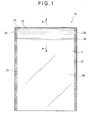
- a package bag 1A provided with a zipper tape includes a bag body 2 provided by overlaying base material films 24 (package material) with each other and forming side seal portions 21 and a top seal portion 22 on the periphery thereof.
- a zipper tape 3A is attached to an inner surface of an opening 23 of the bag body 2.
- Fig. 2 shows a cross section of the zipper tape 3A.
- the zipper tape 3A includes a pair of a male member 32 and a female member 33.
- the male member 32 has a united arrangement of a belt-shaped base 321 bonded to the bag body 2, a head 322 having a substantially arrow-tip shaped cross section, and a connecting portion 323 for connecting the belt-shaped base 321 and the head 322.
- the female member 33 includes a belt-shaped base 331 bonded to the bag body 2, and a first and second hooking portions 332 and 333 connected to the belt-shaped base 331 and exhibiting an arc cross section. The first hooking portion 332 and the second hooking portion 333 are opposed with each other.
- An engagement portion 31 of the zipper tape 3A is provided by the head 322 of the male member 32 and the first and the second hooking portions 332 and 333 of the female member 33, which are disengaged and engaged to open and re-close the bag.
- the belt-shaped base 321 includes: a main body 3211 on which the engagement portion 31 is provided; a first projecting portion 3212 provided on an opening-side of the main body 3211; a thin portion 3213 connected to an opening-side of the first projecting portion 3212; and a second projecting portion 3214 connected to an opening-side of the thin portion 3213.
- a surface 3212B of the first projecting portion 3212 on the side of the base material film 24 and a surface 3214B of the second projecting portion 3214 on the side of the base material film 24 are substantially coplanarly positioned.
- the thin portion 3213 is located at a position recessed relative to the surfaces 3212B and 3214B.
- a level difference is provided between the thin portion 3213 and the first and the second projecting portions 3212 and 3214. Further, the position of the thin portion 3213 is also recessed relative to a surface 3212C of the first projecting portion 3212 on the side of the engagement portion 31 and a surface 3214C of the second projecting portion 3214 on the side of the engagement portion 31.
- the thickness of the thin portion 3213 is preferably 0.12 mm or less. In the present exemplary embodiment, the thickness of the thin portion 3213 is 0.1 mm.
- the thickness of the main body 3211 is preferably 0.15 mm.
- the thickness of the first and the second projecting portions 3212 and 3214 of the main body 3211 is preferably in a range between 0.20 mm and 1 mm, which may exemplarily be set at 0.3 mm.
- the width of the thin portion 3213 is preferably in a range between 0.5 mm and 5 mm, more preferably between 1 mm and 3 mm. In this exemplary embodiment, the width is set at 2 mm.
- Ribs 34 having the same height as the height of the first and the second projecting portions 3212 and 3214 are provided on the main body 3211 of the belt-shaped base 321 on a closed side relative to the engagement portion 31. Though the number of the ribs 34 is not limited, four ribs 34 are provided in the present exemplary embodiment.
- the belt-shaped base 331 also includes: a main body 3311 on which the engagement portion 31 is provided; a first projecting portion 3312 provided on an opening-side of the main body 3311; a thin portion 3313 connected to an opening-side of the first projecting portion 3312; and a second projecting portion 3314 connected to an opening-side of the thin portion 3313.
- the thin portion 3313 is provided at the same location as the thin portion 3213 of the belt-shaped base 321, where a level difference is provided between the thin portion 3313 and the first and the second projecting portions 3312 and 3314.
- the thickness of the respective portions are set similarly to that of the belt-shaped base 321, where the thickness of the thin portion 3313 is exemplarily 0.1 mm, the thickness of the main body 3311 is exemplarily 0.15 mm and the thickness of the first and the second projecting portions 3312 and 3314 of the main body 3311 is exemplarily 0.3 mm.
- the width of the thin portion 3313 is 2 mm.
- Four ribs 34 are provided on the main body 3311 near the closed side relative to the engagement portion 31.
- a space is defined by a surface 3213A of the thin portion 3213 of the male member 32, the film of the bag body 2, and a surface 3212A of the first projecting portion 3212 and a surface 3214A of the second projecting portion 3214 intersecting the surface 3213A of the thin portion 3213.
- a space is provided in the female member 33 by the thin portion 3313, the film of the bag body 2, and a surface 3312A of the first projecting portion 3312 and a surface 3314A of the second projecting portion 3314 intersecting a surface 3313A of the thin portion 3313.
- V-shaped notches 25 that provide an opening start position are respectively provided on both ends of the thin portion 3213 and the thin portion 3313 ( Fig. 1 ).
- the zipper tape 3A can be integrally produced by a co-extrusion molding. With the use of co-extrusion molding for producing the zipper tape 3A, the producing step can be simplified, the production cost can be lowered and the zipper tape 3A can be continuously produced in a stable manner.
- any material may be used for producing the male member 32 and female member 33 of the zipper tape 3A as long as the male and female members are reclosable.
- polyolefin-base resin including typical polyethylene-base resin such as low-density polyethylene and linear low-density polyethylene and polypropylene-base resin is used.
- polypropylene-base resins are thermoplastic resin such as homo-polypropylene, block polypropylene, random polypropylene (RPP), propyleneethylene-butene-1-random ternary copolymer, polyolefinic specialty soft resin (TPO resin. e.g. prime polymer TPO) and mixture of the resins.
- the base material film 24 (package material) forming the bag body 2 is preferably a laminate film in which a sealant layer 241 is laminated on a base layer 242.
- a laminate film in which an intermediate layer (not shown) such as a gas-barrier layer, light-shielding layer and strength-improving layer is laminated between the base layer 242 and the sealant layer 241 may alternatively be used.
- biaxially oriented polypropylene film As well as biaxially oriented polypropylene film (OPP film), a biaxially oriented polyester film such as a biaxially oriented polyethylene terephthalate film (PET film) and a biaxially oriented polyethylene naphthalate film (PEN film), and a biaxially oriented polyamide film such as nylon 6, nylon 66 and MXD6 (poly-(meta-xylylene adipamide)) can be suitably used for the base layer 242.
- PET film biaxially oriented polyethylene terephthalate film
- PEN film biaxially oriented polyethylene naphthalate film
- a biaxially oriented polyamide film such as nylon 6, nylon 66 and MXD6 (poly-(meta-xylylene adipamide)
- nylon 6, nylon 66 and MXD6 poly-(meta-xylylene adipamide
- the intermediate layer when the intermediate layer is a gas-barrier layer, the intermediate layer may be provided by a film of saponified ethylene-vinyl acetate copolymer (EVOH), polyvinylidene chloride (PVDC) and polyacrylonitrile (PAN), aluminum foil, a vapor-deposition layer of silica, alumina, aluminum and the like, or a coating layer of PVDC.
- EVOH ethylene-vinyl acetate copolymer
- PVDC polyvinylidene chloride
- PAN polyacrylonitrile
- the intermediate layer may be vapor-deposited or coated on the inner surface of the base layer 242.
- the layer may be vapor-deposited or coated on a separate biaxially oriented nylon film (ONy film), biaxially oriented polyethylene terephthalate film (PET film), biaxially oriented polypropylene film (OPP film) and the like and thus prepared film may be laminated on the intermediate layer.
- biaxially oriented nylon film ONy film
- PET film biaxially oriented polyethylene terephthalate film
- OPP film biaxially oriented polypropylene film
- aluminum foil and aluminum vapor-deposited layer are opaque, aluminum foil and aluminum vapor-deposited layer can also work as a light-shielding layer.
- Low-density polyethylene, polypropylene (CPP) and the like can be used as the innermost sealant layer 241.
- the above resins may be formed as a film, which is to be laminated by a dry lamination or an extrusion lamination. Alternatively, the above resins may be laminated by extrusion coating to obtain the base material film 24.
- the package bag 1A provided with the zipper tape is produced using a zipper-tape-attaching three-side seal bag-making machine and the like.
- the zipper-tape-attaching three-side seal bag-making machine includes a package material feeder, a tape feeder and a zipper tape bonding section. After a pair of the base material films 24 are fed from the package material feeder, the zipper tape 3A fed from the tape feeder is disposed between the pair of the base material films 24 and the zipper tape 3A and the base material films 24 are bonded at the zipper tape bonding section. Subsequently, the base material films 24 are transferred to be bonded and melt-cut at a predetermined interval in the transferring direction of the base material film 24 to form the package bag 1A provided with the zipper tape.
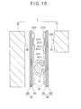
- FIG. 3 A cross section illustrating the point-seal process is shown in Fig. 3 .
- a producing machine 4 is provided with point seal bars 41 and 42.
- a convex portion 43 is provided on the point seal bar 41.
- the cross section of the convex portion 43 is preferably substantially trapezoidal.
- a short side 43B of the substantially trapezoidal cross section is provided by a cut surface of an end surface 43A of the convex portion 43.
- a long side 43C of the substantially trapezoidal cross section is provided by a side opposing to the end surface 43A of the convex portion 43.
- the length of the short side 43B is 2 mm, which is the same as the width of the thin portion 3213.
- the length of the long side 43C is not limited as long as the long side 43C is longer than the short side 43B. In this exemplary embodiment, the length of the long side 43C is 4.2 mm.
- the height of the convex portion 43 is set higher than the height of the space provided between the thin portion 3213 or the thin portion 3313 and the base material film 24. During the point seal process using the producing machine 4, the convex portion 43 is pressed onto the thin portions 3213 and 3313 over the base material films 24 to apply a force from the center of the thin portions 3213 and 3313 toward an outside to melt and flatten the zipper tape.
- a point seal bar having a contact surface smaller than the contact surface of the convex portion 43 may be used to conduct a sealing process. According to the above arrangement, the flattening process can be more stably conducted.
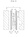
- Fig. 4 shows a cross section of the thus-sealed thin portion at the side seal portion 21. The width of the thin portions 3213 and 3313 is maintained. Further, since the convex portion 43 having substantially trapezoidal cross section is used to seal, thin section wider than the thin portions 3213 and 3313 is provided.
- the space is defined by the film of the bag body 2, the surface 3213A of the thin portion 3213 opposing to the film of the bag body 2, and the surface 3212A of the first projecting portion 3212 and the surface 3214A of the second projecting portion 3214 intersecting the surface 3213A of the thin portion 3213. Accordingly, since a level difference is provided between the thin portion 3213 and the first projecting portion 3212 and between the thin portion 3213 and the second projecting portion 3214, the thin portion 3213 is easily cut along the level difference when the bag is to be opened.
- the bag is more likely to be cut between the thin portion 3213 and the first and the second projecting portions 3312 and 3214.
- a space is also provided in the belt-shaped base 331 by the film of the bag body 2, the surface 3313A of the thin portion 3313 opposing to the film of the bag body 2, and a surface 3312A of the first projecting portion 3312 and a surface 3314A of the second projecting portion 3314 intersecting the surface 3313A of the thin portion 3313. Accordingly, since a level difference is provided between the thin portion 3313 and the first projecting portion 3312 and between the thin portion 3313 and the second projecting portion 3314, the thin portion 3313 is easily cut along the level difference when the bag is to be opened.
- the bag is more likely to be cut between the thin portion 3313 and the first and the second projecting portions 3312 and 3314. Accordingly, linearity can be provided to the cutting line, so that easy-openability can be achieved without damaging the zipper tape 3A.
- the thickness of the thin portion is 0.12 mm or less, the thickness of the first and the second projecting portions is in a range between 0.20 mm and 1 mm, and the width of the thin portion is in a range between 0.5 mm and 5 mm. Accordingly, the thin portion is easily cut while the first and the second projecting portions are not likely to be cut. Consequently, the tape is likely to be cut along the thin portion, so that linearity as well as easy-splittability can be provided to the cutting line. Further, since the first and the second projecting portions are not too thick, excellent sealability can be exhibited without influencing on the workability.
- the male member 32 provided with the main body 3211, the first projecting portion 3212, the thin portion 3213 and the second projecting portion 3214 and the female member 33 provided with the first projecting portion 3312, the thin portion 3313 and the second projecting portion 3314 can be respectively produced by co-extrusion in a single step. Accordingly, the respective components can be easily produced without requiring much work and cost.
- the seal bar can be evenly touched to the entire surface of the zipper tape 3A when the zipper tape 3A and the base material film 24 are fused. Consequently, the zipper tape 3A can be securely and stably fused onto the base material film 24.
- the convex portion 43 is provided on the point seal bar 41, when being sealed with the use of the point seal bar 41, the thin portions 3213 and 3313 are initially brought into contact with the point seal bars 41 and 42 to be melted. As a result, the molten resin of the thick first and second projecting portions 3212 and 3214 does not enter into the thin portions 3213 and 3313, so that the width of the thin portions 3213 and 3313 can be maintained. Further, since the convex portion 43 has approximately trapezoidal cross section, the thin area can be enlarged. Consequently, the notch 25 can be stably provided, thus improving easy-splittability.
- the second exemplary embodiment is the same as the first exemplary embodiment except that the lengths of the opposing thin portions 3213 and 3313 are different and that the resin used for the thin portions 3213 and 3313 is different from the resins used for the first projecting portions 3212 and 3312 and the second projecting portions 3214 and 3314 are different. Accordingly, detailed explanation of the common arrangement will not be mentioned below.
- the length of the thin portion 3213 of the male member 32 is shorter than the thin portion 3313 of the female member 33.
- the resin used for the thin portion 3213 is different from the resin used for the second projecting portion 3214 and the first projecting portion 3212 provided on both ends of the thin portion 3213.
- the used resin is the resins used in the first exemplary embodiment, from which a combination of different resins can be selected as necessary. For instance, low-density polyethylene and polypropylene can be selected.
- the lengths of the opposing thin portions 3213 and 3313 differ in the second exemplary embodiment, when the package bag 1B attached with the zipper tape 3B is opened, the opposing base material films 24 are cut at different levels. Accordingly, when the re-closed package bag 1B is re-opened, the base material film 24 at the opening can be easily pinched.
- the resin used for the thin portion 3213 is different from the resin used for the first and the second projecting portions 3212 and 3214. Accordingly, interlayer peeling is likely to occur between the thin portion and the first and the second projecting portions, so that linearity can be given to the cutting line. Further, since interlayer peeling occurs between the thin portion and the projecting portion(s), no cutting chip is generated from the torn portion, so that sanitary product can be provided.
- the third exemplary embodiment is the same as the first exemplary embodiment except that a zipper tape 3C is provided with the thin portion 3313 and the second projecting portion 3314 only on the belt-shaped base 331 of the female member 33.
- the length of the belt-shaped base 321 of the male member 32 is preferably adjusted so that the position of the opening-side end-surface 3212A is not aligned with a boundary surface 3312A between the first projecting portion 3312 and the thin portion 3313 of the female member 33. Accordingly, since the opposing base material films 24 are unevenly (asymmetrically) cut along cutting lines F to G, the base material film 24 can be easily pinched when the bag is re-opened.
- the package bag 1C provided with the zipper tape is sealed while the second projecting portion 3314 and the opposing base material film 24 are fused.
- the bag is cut to be opened along cutting lines F, G or E connecting: the level difference between the thin portion 3313 and the second projecting portion 3314 or between the thin portion 3313 and the first projecting portion 3312; and the opposing first projecting portion 3212. Since the thin portion 3313 is provided only on one side, the bag can be opened with smaller force, thus achieving easy-openability. Further, since the first and the second projecting portions 3312 and 3314 are thicker than the thin portion 3313, even when the cutting line goes off an intended cutting line, the cutting line can be returned to an original cutting position.
- the four ribs 34 are provided on the main bodies 3211 and 3311 of the belt-shaped bases 32 and 33 on a closed side relative to the engagement portion 31 in this exemplary embodiment, the number of the ribs 34 is not restricted. Further, the rib 34 may not be provided as shown in Fig. 7 .
- the convex portion 43 is provided on the point seal bar 41 in order to collapse the thin portion at the side seal portion 21, a recessed portion 44 to be fitted with the convex portion 43 may be provided on the point seal bar 42 as shown in Fig. 8 .
- the thin portion can be reliably spread to be thin and wide.
- the convex portion 43 may have a substantially arc cross section as shown in Fig. 9 .
- convex portions 43 may be provided on the point seal bars 41 and 42 at positions opposing with each other.
- a recessed portion 45 shaped along the cross section of the engagement portion 31 may be provided on the point seal bar 41 as shown in Fig. 11 .
- the thin portion can be more stably and accurately melted and flattened.
- a plurality of (e.g. two-stage, three-stage) sealing processes may be applied with point seal bars having differently sized contact surface on the convex portion. According to the above arrangement, the flattening process can be more stably conducted.
- each of the thick first projecting portions 3212 and 3312 is respectively provided on the belt-shaped bases 321 and 331, two or more projecting portions may be provided. With such an arrangement, even when the cutting line is erroneously extended to the first projecting portion 3212 or 3312, the cutting line can be reliably returned to the peeling portion of the thin portions 3213 and 3313.
- the package on which the zipper tape 3 is welded is a three-side seal bag in the above exemplary embodiments
- the invention can be also applied to a bag obtained by the method disclosed in JP-A-2003-155044 or a pillow bag.
- the belt-shaped bases 321 and 331 are provided by a single layer in the above exemplary embodiments, the belt-shaped bases may be provided by a plurality of layers. Especially, when a seal layer is provided on a side of the belt-shaped bases 321 and 331 to be welded to the bag body, a resin having excellent adhesiveness with the sealant layer 241 of the base material film 24 of the bag body 2 can be used for the seal layer. Accordingly, irrespective of the material used for the base material film 24 of the bag body 2, a zipper tape with excellent adhesiveness can be produced.
- Example 1 Example 1
- a zipper tape was prepared under different conditions as in the following examples and comparative examples. Subsequently, tearing resistance and the generation of cutting chips were examined.
- a zipper tape including a pair of male member and a female member as shown in Fig. 3 was obtained by co-extrusion.
- the used resin, the length of the thin portion and the thickness of the respective portions were as follows:
- the package bag provided with the easy-tearable zipper tape shown in Figs. 1 and 2 was obtained.
- the resin and the length of the thin portion employed in the example 2 were as follows:
- a zipper tape having a thin portion and a second projecting portion only on a female member was used to obtain a zipper tape by co-extrusion including a pair of a male member and a female member shown in Fig. 4 .
- the used resin, the length of the thin portion and the thickness of the respective portions employed in the example 5 were as follows:
- a zipper tape provided with an easily-cuttable resin layer on a tape portion (see Example 1 of JP-A-2004-244027 ) and the above films were formed into a bag using a zipper-tape-attaching three-side bag-making machine to obtain a package bag provided with the zipper tape. Incidentally, after heat-sealing the side portion of the bag, notches are provided between the tape portion of the zipper tape and the easily-cuttable resin layer.
- a zipper tape provided with a cut tape on a belt-shaped base of a zipper tape (see Fig. 12 of JP-A-2004-276925 ) and the above films were formed into a bag using a zipper-tape-attaching three-side bag-making machine to obtain a package bag provided with the zipper tape.
- a notch is provided on both sides of an opening string.
- a zipper tape not provided with the first and the second projecting portions and having the same thickness as a main body except for a thin portion was produced, which was used to form a bag by a three-side bag-making machine to obtain a package bag provided with a zipper tape.
- the resin and the length of the thin portion employed in the comparative example 4 were as follows:
- the bag was opened by tearing the front and back films from the notch provided on the side portion of the bag.
- a portion between the two notches provided on the end of the cut tape (thin portion) was pulled to cut the film of the bag body together with the cut tape (thin portion).
- the package bag according to the examples 1 and 6 could be easily cut without feeling tearing resistance. Further, no cutting chip was produced in opening the bag. Though no excessive tearing resistance was felt in the comparative example 1, cutting chip was generated in opening the bag. The bag according to the comparative example 2 exhibited great tearing resistance, which could not be easily opened. No cutting chip was produced. The bag according to the comparative example 3 exhibited great tearing resistance on account of short thin portion, which could not be easily opened. The both sides of the thin portion of the comparative example 4 were thin, so that the both sides were cut simultaneously with tearing, which was not capable of linearly cut.
- the invention is widely applicable to package bags provided with a zipper tape for packaging various articles such as food, medicine, medical products and miscellaneous goods.
Applications Claiming Priority (3)
| Application Number | Priority Date | Filing Date | Title |
|---|---|---|---|
| JP2006257556 | 2006-09-22 | ||
| JP2007002886 | 2007-01-10 | ||
| PCT/JP2007/062922 WO2008035494A1 (fr) | 2006-09-22 | 2007-06-27 | Bande de fixation facilement déchirable, procédé de fabrication de la bande de fixation, sac d'emballage avec bande de fixation facilement déchirable, et dispositif et procédé de fabrication du sac d'emballage |
Publications (2)
| Publication Number | Publication Date |
|---|---|
| EP2103541A1 true EP2103541A1 (de) | 2009-09-23 |
| EP2103541A4 EP2103541A4 (de) | 2014-01-08 |
Family
ID=39200324
Family Applications (1)
| Application Number | Title | Priority Date | Filing Date |
|---|---|---|---|
| EP07767722.7A Withdrawn EP2103541A4 (de) | 2006-09-22 | 2007-06-27 | Leicht zerreissbares befestigungsband, verfahren zur herstellung des befestigungsbands, verpackungsbeutel mit leicht zerreissbarem befestigungsband und vorrichtung und verfahren zur herstellung des verpackungsbeutels |
Country Status (8)
| Country | Link |
|---|---|
| US (1) | US8540428B2 (de) |
| EP (1) | EP2103541A4 (de) |
| JP (1) | JP4898817B2 (de) |
| KR (1) | KR101344985B1 (de) |
| CN (1) | CN101522538B (de) |
| CA (1) | CA2664068A1 (de) |
| TW (1) | TWI399326B (de) |
| WO (1) | WO2008035494A1 (de) |
Cited By (3)
| Publication number | Priority date | Publication date | Assignee | Title |
|---|---|---|---|---|
| EP2399845A1 (de) * | 2010-06-24 | 2011-12-28 | Norio Goto | Tetraedrischer Verpackungsbehälter und Verfahren für tetraedrischen Verpackungsbehälter |
| WO2012016115A1 (en) * | 2010-07-29 | 2012-02-02 | Illinois Tool Works Inc. | Tear strip creation on zipper flanges |
| EP3131756A4 (de) * | 2014-04-16 | 2017-10-18 | Stora Enso Oyj | Verfahren zur herstellung eines wärmebeständigen polymerbeschichteten ofenblechs, durch das verfahren herstellbares ofenblech, lebensmittelschale und lebensmittelverpackung |
Families Citing this family (22)
| Publication number | Priority date | Publication date | Assignee | Title |
|---|---|---|---|---|
| JP5319987B2 (ja) * | 2008-08-26 | 2013-10-16 | 出光ユニテック株式会社 | ジッパーテープ及びジッパーテープ付包装袋 |
| JP5118080B2 (ja) | 2009-02-06 | 2013-01-16 | 出光ユニテック株式会社 | 易裂き性ジッパーテープ、および、易裂き性ジッパーテープ付き包装袋 |
| JP2011083378A (ja) * | 2009-10-14 | 2011-04-28 | Idemitsu Unitech Co Ltd | ジッパーテープ、ジッパーテープ付包装袋、ジッパーテープ付包装袋の製造方法およびその製造装置 |
| JP5638278B2 (ja) * | 2009-10-19 | 2014-12-10 | 出光ユニテック株式会社 | 易裂き性ジッパーテープ、及び、易裂き性ジッパーテープ付き包装袋 |
| JP5595026B2 (ja) * | 2009-12-11 | 2014-09-24 | 出光ユニテック株式会社 | ジッパーテープ、及び、ジッパーテープ付き包装袋 |
| JP5639091B2 (ja) * | 2010-02-12 | 2014-12-10 | 出光ユニテック株式会社 | ジッパーテープおよびジッパーテープ付包装袋 |
| JP2011206231A (ja) * | 2010-03-30 | 2011-10-20 | C I Kasei Co Ltd | 嵌合具および嵌合具付き袋体 |
| JP5756268B2 (ja) * | 2010-09-10 | 2015-07-29 | 出光ユニテック株式会社 | ジッパーテープ付き包装袋の製造方法及びジッパーテープ付き包装袋、ならびにジッパーテープ付き包装袋の製造装置 |
| JP6041494B2 (ja) * | 2012-01-23 | 2016-12-07 | 出光ユニテック株式会社 | カットテープ、ジッパーテープ、及び包装袋 |
| US9950819B2 (en) * | 2012-02-28 | 2018-04-24 | Takazono Corporation | Tablet packing method and tablet packing apparatus |
| US20140346076A1 (en) * | 2013-05-24 | 2014-11-27 | Rani Bookvich | Four sided pillow packaging for granola product |
| JP6271890B2 (ja) | 2013-07-12 | 2018-01-31 | 出光ユニテック株式会社 | ジッパーテープ付き袋体、および、その製造方法 |
| JP5651850B1 (ja) * | 2013-12-26 | 2015-01-14 | 日本竹菱株式会社 | カットテープ付きチャックテープ、及びカットテープ付きチャックテープを具備した包装袋 |
| EP3053849B1 (de) * | 2014-04-09 | 2017-09-13 | Kuraray Co., Ltd. | Flüssigkeitsverpackungsbehälter |
| JP2014196145A (ja) * | 2014-06-16 | 2014-10-16 | 出光ユニテック株式会社 | ジッパーテープ、及び、包装袋 |
| CN204137512U (zh) * | 2014-10-17 | 2015-02-04 | 大连竹菱包装工业有限公司 | 一种易撕拉链及其包装袋 |
| JP6487257B2 (ja) * | 2015-03-31 | 2019-03-20 | 出光ユニテック株式会社 | ジッパーテープ体およびジッパーテープ付袋体の製造方法 |
| JP6487256B2 (ja) * | 2015-03-31 | 2019-03-20 | 出光ユニテック株式会社 | ジッパーテープ付袋体の製造方法 |
| JP6113339B1 (ja) | 2016-08-01 | 2017-04-12 | 出光ユニテック株式会社 | テープ及び袋体 |
| JP7320990B2 (ja) * | 2019-05-28 | 2023-08-04 | 株式会社生産日本社 | 生分解性袋体 |
| WO2021054384A1 (ja) | 2019-09-20 | 2021-03-25 | 出光ユニテック株式会社 | テープ、ジッパーテープ、テープ付き容器およびジッパーテープ付き容器 |
| IT202100002633A1 (it) * | 2021-02-05 | 2022-08-05 | Ica Spa | Sistema di chiusura per confezioni con elemento richiudibile ad incastro |
Citations (2)
| Publication number | Priority date | Publication date | Assignee | Title |
|---|---|---|---|---|
| US5660479A (en) * | 1996-02-16 | 1997-08-26 | Reynolds Consumer Products Inc. | Easy open package header |
| US20040031132A1 (en) * | 2002-04-25 | 2004-02-19 | Vandenheuvel Greg J. | Closure arrangement with tear guide for allowing access to zipper flanges in a package |
Family Cites Families (76)
| Publication number | Priority date | Publication date | Assignee | Title |
|---|---|---|---|---|
| US3780781A (en) * | 1971-09-07 | 1973-12-25 | Seisan Nipponsha Kk | Openable bag |
| US4363345A (en) * | 1980-06-02 | 1982-12-14 | Union Carbide Corporation | Reclosable container |
| US4430070A (en) * | 1981-08-11 | 1984-02-07 | Minigrip, Inc. | Method of and apparatus for uninterruptedly assembling components for making bags |
| JPH0754823B2 (ja) * | 1986-09-03 | 1995-06-07 | 松下電子工業株式会社 | リードフレーム収納具 |
| JPS6362349U (de) | 1986-10-13 | 1988-04-25 | ||
| US5067822A (en) * | 1989-04-24 | 1991-11-26 | Reynolds Consumer Products, Inc. | Method of forming recloseable packages, profiles used therein, and packages produced thereby |
| US5238306A (en) * | 1989-05-19 | 1993-08-24 | Reynolds Consumer Products, Inc. | Method of producing a sealing system for a reclosable webbed-wall package, and system made |
| US5092684A (en) * | 1991-03-04 | 1992-03-03 | Illinois Tool Works Inc. | Post-applied zipper base with grip strip |
| TW243431B (en) * | 1991-05-31 | 1995-03-21 | Gen Foods Inc | Pouch having easy opening and reclosing characteristics and method and apparatus for production thereof |
| US5356222A (en) * | 1992-02-24 | 1994-10-18 | Reynolds Consumer Products Inc. | Interlocking closure for plastic storage bags with confirming color stripes |
| CA2164120A1 (en) * | 1993-06-28 | 1995-01-05 | Jose Porchia | Flexible thermoplastic containers having a visual pattern thereon |
| US5486051A (en) * | 1994-04-11 | 1996-01-23 | Reynolds Consumer Products Inc. | Closure arrangement having a breakaway seal |
| US5470156A (en) * | 1994-04-11 | 1995-11-28 | Reynolds Consumer Products, Inc. | Closure arrangement having a peelable seal |
| US5904425A (en) * | 1994-04-11 | 1999-05-18 | Reynolds Consumer Products, Inc. | Closure arrangement having a peelable seal |
| US5564834A (en) * | 1994-04-15 | 1996-10-15 | Dowbrands L.P. | Adhesive closure having enhanced burst strength for flexible bag |
| US5832145A (en) * | 1994-04-15 | 1998-11-03 | Dowbrands L.P. | Adhesive closure for flexible bag |
| US5609420A (en) * | 1994-06-01 | 1997-03-11 | Minigrip, Inc. | Reclosable bag closure with tear containing strips |
| US5492411A (en) * | 1995-01-18 | 1996-02-20 | Reynolds Consumer Products Inc. | Tamper evident peelable seal |
| JPH08268442A (ja) * | 1995-03-30 | 1996-10-15 | Toshiichi Yamada | 易開封性包装袋及び開封誘導フィルム付きジッパー |
| US5552202A (en) * | 1995-07-11 | 1996-09-03 | Reynolds Consumer Products Inc. | Tear guide arrangement |
| US5664303A (en) * | 1995-11-06 | 1997-09-09 | Illinois Tool Works Inc. | Differential flange header package |
| US5628566A (en) * | 1996-01-29 | 1997-05-13 | Reynolds Consumer Products, Inc. | Profile sealing flange |
| US5718024A (en) * | 1996-02-05 | 1998-02-17 | Reynolds Consumer Products, Inc. | Closure arrangement with tapered flange |
| US6217216B1 (en) * | 1996-02-22 | 2001-04-17 | Nossi Taheri | Reclosable plastic bag with non-perforated tear zone |
| JP3650465B2 (ja) * | 1996-04-12 | 2005-05-18 | 出光興産株式会社 | 咬合具及び咬合具付き包装袋 |
| JPH1059384A (ja) | 1996-08-12 | 1998-03-03 | Heisei Polymer Co Ltd | 引裂き開封袋 |
| US5749658A (en) * | 1996-09-12 | 1998-05-12 | Reynolds Consumer Products, Inc. | Closure arrangement for attachment to outside of bag |
| US6350057B1 (en) * | 1997-05-22 | 2002-02-26 | Sealstrip Corp. | Reinforced reclosable package seals |
| US6030122A (en) * | 1998-03-06 | 2000-02-29 | Illinois Tool Works Inc. | Pinch-grip zipper |
| US6004032A (en) * | 1998-06-30 | 1999-12-21 | Reynolds Consumer Products, Inc. | Tamper-evident closure arrangements and methods |
| US6210038B1 (en) * | 1998-11-03 | 2001-04-03 | Reynolds Consumer Products, Inc. | Closure arrangement having a peelable seal indicator |
| US6991375B2 (en) * | 1998-11-06 | 2006-01-31 | Velcro Industries B.V. | Reclosable packaging |
| US6154934A (en) * | 1999-02-10 | 2000-12-05 | Illinois Tool Works, Inc. | Reclosable zipper with fusible rib layer |
| US6318894B1 (en) * | 1999-10-06 | 2001-11-20 | Kraft Foods Holdings, Inc. | Resealable flexible packages having hook design tear line |
| US6131370A (en) * | 2000-02-09 | 2000-10-17 | Illinois Tool Works Inc. | Zipper applied across a film in transverse direction |
| US6345911B1 (en) * | 2000-06-06 | 2002-02-12 | American Innotek, Inc. | Lock top canister bag and method of manufacture |
| US6871473B1 (en) * | 2000-08-10 | 2005-03-29 | Pactiv Corporation | Method and apparatus for making reclosable plastic bags using a pre-applied slider-operated fastener |
| US6691491B2 (en) * | 2000-08-18 | 2004-02-17 | Pacmac, Inc. | Vertical form, fill and seal packaging machine |
| US6354738B1 (en) * | 2000-10-24 | 2002-03-12 | Illinois Tool Works Inc. | Tamper evident reclosable plastic bag |
| US20020094137A1 (en) * | 2001-01-16 | 2002-07-18 | Schneider John H. | Tamper evident resealable packaging |
| US6553740B2 (en) * | 2001-06-20 | 2003-04-29 | Illinois Tool Works Inc. | Transverse direction zipper applicator and method |
| US6481890B1 (en) * | 2001-07-16 | 2002-11-19 | Reynolds Consumer Products, Inc. | Reclosable zipper having intermittent thickened flange; package; and methods |
| US6899460B2 (en) * | 2001-10-23 | 2005-05-31 | S.C. Johnson Home Storage, Inc. | Storage bag with openly biased mouth |
| JP4074083B2 (ja) | 2001-11-19 | 2008-04-09 | 大日本印刷株式会社 | チャックテープ付きガセット袋およびその製造方法 |
| US6659643B2 (en) * | 2002-02-04 | 2003-12-09 | Illinois Tool Works Inc. | Barrier arrangements for plastic bags |
| US6976787B2 (en) * | 2002-04-11 | 2005-12-20 | Illinois Tool Works Inc. | Slider-operated rocking zipper for reclosable packaging |
| US6830377B2 (en) * | 2002-05-30 | 2004-12-14 | Illinois Tool Works Inc. | Reclosable packaging with gas barrier incorporated in zipper |
| US20030236158A1 (en) * | 2002-06-24 | 2003-12-25 | Pawloski James C. | Method of and apparatus for producing a reclosable pouch |
| US20030235352A1 (en) * | 2002-06-24 | 2003-12-25 | Plourde Eric P. | Transverse direction zipper tape |
| US6810642B2 (en) * | 2002-08-05 | 2004-11-02 | Illinois Tool Works Inc. | Method and apparatus for sealing zippers to bag making film |
| US6910995B2 (en) * | 2002-08-07 | 2005-06-28 | Illinois Tool Works Inc. | Easy open feature for reclosable bags having a longitudinal fin seal |
| US20040078938A1 (en) * | 2002-10-23 | 2004-04-29 | Pawloski James C. | Closure device for a reclosable pouch |
| US20040131283A1 (en) * | 2002-12-03 | 2004-07-08 | Sprague Paul A. | Autoclavable reclosable package |
| JP4145677B2 (ja) | 2003-02-10 | 2008-09-03 | シーアイ化成株式会社 | 易カット性嵌合具及び嵌合具付袋体 |
| US6951421B2 (en) * | 2003-02-14 | 2005-10-04 | Illinois Tool Works Inc. | Reclosable packaging having slider-operated string zipper |
| JP2004276925A (ja) | 2003-03-13 | 2004-10-07 | Idemitsu Unitech Co Ltd | 咬合具及び包装袋 |
| US7137736B2 (en) * | 2003-05-19 | 2006-11-21 | S.C. Johnson Home Storage, Inc. | Closure device for a reclosable pouch |
| US7216405B2 (en) * | 2004-03-25 | 2007-05-15 | Reynolds Consumer Products, Inc. | Teardrop sealant layer for profile and spacer areas for improved sealing and guiding |
| CN2723356Y (zh) * | 2004-05-09 | 2005-09-07 | 蔡玲隆 | 一种食品包装袋 |
| JP4856853B2 (ja) * | 2004-05-21 | 2012-01-18 | 出光ユニテック株式会社 | チャックテープ及びチャックテープ付き包装袋 |
| US7850368B2 (en) * | 2004-06-04 | 2010-12-14 | S.C. Johnson & Son, Inc. | Closure device for a reclosable pouch |
| US7290660B2 (en) * | 2004-07-23 | 2007-11-06 | Tilman Paul A | Storage system having a disposable vacuum bag |
| JP4339768B2 (ja) * | 2004-09-17 | 2009-10-07 | 日本発條株式会社 | 車両用シート |
| CN101072715B (zh) * | 2004-12-07 | 2011-03-23 | 出光统一科技株式会社 | 卡扣以及带有卡扣的袋 |
| FR2884119B1 (fr) * | 2005-04-08 | 2007-06-15 | S2F Flexico Sarl | Profiles de fermeture bimatiere pour sachets |
| US20070206888A1 (en) * | 2006-03-06 | 2007-09-06 | Chia-Hsiang Chang | Multi-pocket specimen bag incorporating easy tear lines for removal of pre-sealed inserts |
| US20070258663A1 (en) * | 2006-05-02 | 2007-11-08 | Illinois Tool Works Inc. | Sculpted header seal for reclosable bags |
| US7410453B2 (en) * | 2006-06-12 | 2008-08-12 | Illinois Tool Works Inc. | Method of sealing a zipper with concave bridges or bases using convex sealing bars |
| JP4874742B2 (ja) * | 2006-08-21 | 2012-02-15 | 出光ユニテック株式会社 | カットテープ付きチャックテープ、その製造方法、およびチャックテープ付き包装袋 |
| KR101466999B1 (ko) * | 2006-10-02 | 2014-12-01 | 이데미쓰 유니테크 가부시키가이샤 | 척 테이프, 척 테이프 부착 포장 주머니 및 이들의 제조 방법 |
| JP5032945B2 (ja) * | 2007-11-08 | 2012-09-26 | 出光ユニテック株式会社 | カットテープおよびカットテープ付き包装袋 |
| US20090297071A1 (en) * | 2008-05-28 | 2009-12-03 | Illinois Tool Works Inc. | Flexible bag with vent for pressure release |
| JP5319987B2 (ja) * | 2008-08-26 | 2013-10-16 | 出光ユニテック株式会社 | ジッパーテープ及びジッパーテープ付包装袋 |
| JP5638278B2 (ja) * | 2009-10-19 | 2014-12-10 | 出光ユニテック株式会社 | 易裂き性ジッパーテープ、及び、易裂き性ジッパーテープ付き包装袋 |
| US20110162329A1 (en) * | 2010-01-05 | 2011-07-07 | Flair Flexible Packaging Corporation | Bag having both permanent and resealable seals |
| US8550715B2 (en) * | 2010-01-19 | 2013-10-08 | Illinois Tool Works Inc. | Zipper with intermeshing flange contours cross-reference to related applications |
-
2007
- 2007-06-27 EP EP07767722.7A patent/EP2103541A4/de not_active Withdrawn
- 2007-06-27 US US12/442,204 patent/US8540428B2/en active Active
- 2007-06-27 CA CA002664068A patent/CA2664068A1/en not_active Abandoned
- 2007-06-27 WO PCT/JP2007/062922 patent/WO2008035494A1/ja active Application Filing
- 2007-06-27 JP JP2008535281A patent/JP4898817B2/ja active Active
- 2007-06-27 CN CN2007800352916A patent/CN101522538B/zh active Active
- 2007-06-27 KR KR1020097006115A patent/KR101344985B1/ko active IP Right Grant
- 2007-06-29 TW TW96123867A patent/TWI399326B/zh active
Patent Citations (2)
| Publication number | Priority date | Publication date | Assignee | Title |
|---|---|---|---|---|
| US5660479A (en) * | 1996-02-16 | 1997-08-26 | Reynolds Consumer Products Inc. | Easy open package header |
| US20040031132A1 (en) * | 2002-04-25 | 2004-02-19 | Vandenheuvel Greg J. | Closure arrangement with tear guide for allowing access to zipper flanges in a package |
Non-Patent Citations (1)
| Title |
|---|
| See also references of WO2008035494A1 * |
Cited By (7)
| Publication number | Priority date | Publication date | Assignee | Title |
|---|---|---|---|---|
| EP2399845A1 (de) * | 2010-06-24 | 2011-12-28 | Norio Goto | Tetraedrischer Verpackungsbehälter und Verfahren für tetraedrischen Verpackungsbehälter |
| TWI421199B (zh) * | 2010-06-24 | 2014-01-01 | Norio Goto | 四面體形包裝容器及四面體形包裝容器方法 |
| US8939643B2 (en) | 2010-06-24 | 2015-01-27 | Norio Goto | Tetrahedral shape packaging container and a tetrahedral shape packaging container method |
| WO2012016115A1 (en) * | 2010-07-29 | 2012-02-02 | Illinois Tool Works Inc. | Tear strip creation on zipper flanges |
| US9238526B2 (en) | 2010-07-29 | 2016-01-19 | Illinois Tool Works Inc. | Tear strip creation on zipper flanges |
| EP3131756A4 (de) * | 2014-04-16 | 2017-10-18 | Stora Enso Oyj | Verfahren zur herstellung eines wärmebeständigen polymerbeschichteten ofenblechs, durch das verfahren herstellbares ofenblech, lebensmittelschale und lebensmittelverpackung |
| US10632725B2 (en) | 2014-04-16 | 2020-04-28 | Stora Enso Oyj | Method of producing a heat-resistant polymer-coated oven board, an oven board obtainable by the method, a food tray and a food package |
Also Published As
| Publication number | Publication date |
|---|---|
| JPWO2008035494A1 (ja) | 2010-01-28 |
| WO2008035494A1 (fr) | 2008-03-27 |
| TW200824975A (en) | 2008-06-16 |
| CN101522538B (zh) | 2012-06-13 |
| KR101344985B1 (ko) | 2013-12-24 |
| US20100074562A1 (en) | 2010-03-25 |
| JP4898817B2 (ja) | 2012-03-21 |
| US8540428B2 (en) | 2013-09-24 |
| CA2664068A1 (en) | 2008-03-27 |
| EP2103541A4 (de) | 2014-01-08 |
| KR20090054455A (ko) | 2009-05-29 |
| CN101522538A (zh) | 2009-09-02 |
| TWI399326B (zh) | 2013-06-21 |
Similar Documents
| Publication | Publication Date | Title |
|---|---|---|
| US8540428B2 (en) | Easily tearable fastener tape, method of producing the fastener tape, packaging bag with easily tearable fastener tape, and device and method for producing the packaging bag | |
| EP2055643B1 (de) | Spannband mit schneidband, herstellungsverfahren dafür und verpackungsbeutel mit spannband | |
| US7736058B2 (en) | Chuck tape and packaging bag with chuck tape | |
| EP2851312B1 (de) | Reißverschluss und Beutel mit Reißverschluss | |
| US8789247B2 (en) | Interlock tool, bag making use thereof and process for producing them | |
| EP2221255B1 (de) | Schneidband und verpackungsbeutel mit einem schneidband | |
| EP2077236A1 (de) | Leicht zu öffnendes befestigungsband, verpackungsbeutel mit leicht zu öffnendem befestigungsband und verfahren zur herstellung eines leicht zu öffnenden befestigungsbands | |
| EP2394924B1 (de) | Leicht aufreissbares reissverschlussband und verpackungsbeutel mit dem leicht aufreissbaren reissverschlussband | |
| EP1982610A1 (de) | Reissverschlussband, verpackungsbeutel mit reissverschlussband und vorrichtung zur herstellung von verpackungsbeuteln mit reissverschlussbändern | |
| US20140233869A1 (en) | Easily openable fastener tape, packaging bag with easily openable fastener tape, and method of manufacturing easily openable fastener tape | |
| JP2006062733A (ja) | 再開閉機能を有する包装方法 |
Legal Events
| Date | Code | Title | Description |
|---|---|---|---|
| PUAI | Public reference made under article 153(3) epc to a published international application that has entered the european phase |
Free format text: ORIGINAL CODE: 0009012 |
|
| 17P | Request for examination filed |
Effective date: 20090421 |
|
| AK | Designated contracting states |
Kind code of ref document: A1 Designated state(s): AT BE BG CH CY CZ DE DK EE ES FI FR GB GR HU IE IS IT LI LT LU LV MC MT NL PL PT RO SE SI SK TR |
|
| DAX | Request for extension of the european patent (deleted) | ||
| A4 | Supplementary search report drawn up and despatched |
Effective date: 20131206 |
|
| RIC1 | Information provided on ipc code assigned before grant |
Ipc: B65D 33/25 20060101AFI20131202BHEP Ipc: B65D 33/00 20060101ALI20131202BHEP |
|
| 17Q | First examination report despatched |
Effective date: 20140722 |
|
| STAA | Information on the status of an ep patent application or granted ep patent |
Free format text: STATUS: THE APPLICATION IS DEEMED TO BE WITHDRAWN |
|
| 18D | Application deemed to be withdrawn |
Effective date: 20150203 |