EP2101935B1 - Werkstück und verfahren für das explosionsumformen - Google Patents
Werkstück und verfahren für das explosionsumformen Download PDFInfo
- Publication number
- EP2101935B1 EP2101935B1 EP07856437.4A EP07856437A EP2101935B1 EP 2101935 B1 EP2101935 B1 EP 2101935B1 EP 07856437 A EP07856437 A EP 07856437A EP 2101935 B1 EP2101935 B1 EP 2101935B1
- Authority
- EP
- European Patent Office
- Prior art keywords
- material supply
- workpiece
- preformed material
- process according
- preformed
- Prior art date
- Legal status (The legal status is an assumption and is not a legal conclusion. Google has not performed a legal analysis and makes no representation as to the accuracy of the status listed.)
- Not-in-force
Links
- 238000000034 method Methods 0.000 title claims description 25
- 238000004880 explosion Methods 0.000 title claims description 13
- 239000000463 material Substances 0.000 claims description 87
- 230000008569 process Effects 0.000 claims description 17
- 238000005474 detonation Methods 0.000 claims description 13
- 238000007373 indentation Methods 0.000 claims description 4
- 239000000203 mixture Substances 0.000 claims description 4
- 239000002360 explosive Substances 0.000 claims description 3
- 238000004200 deflagration Methods 0.000 description 5
- 238000000465 moulding Methods 0.000 description 3
- 238000005096 rolling process Methods 0.000 description 3
- 238000007493 shaping process Methods 0.000 description 3
- 238000012549 training Methods 0.000 description 3
- 206010040954 Skin wrinkling Diseases 0.000 description 2
- 238000002485 combustion reaction Methods 0.000 description 2
- 239000007788 liquid Substances 0.000 description 2
- 239000002184 metal Substances 0.000 description 2
- 230000004048 modification Effects 0.000 description 2
- 238000012986 modification Methods 0.000 description 2
- 230000009466 transformation Effects 0.000 description 2
- 238000003466 welding Methods 0.000 description 2
- 230000009471 action Effects 0.000 description 1
- 238000013459 approach Methods 0.000 description 1
- 238000005452 bending Methods 0.000 description 1
- 238000006243 chemical reaction Methods 0.000 description 1
- 238000011161 development Methods 0.000 description 1
- 230000018109 developmental process Effects 0.000 description 1
- 230000000694 effects Effects 0.000 description 1
- 238000005516 engineering process Methods 0.000 description 1
- 239000012530 fluid Substances 0.000 description 1
- 238000005552 hardfacing Methods 0.000 description 1
- 238000010438 heat treatment Methods 0.000 description 1
- 238000005304 joining Methods 0.000 description 1
- 238000004519 manufacturing process Methods 0.000 description 1
- 238000003825 pressing Methods 0.000 description 1
- 238000007789 sealing Methods 0.000 description 1
- 230000035939 shock Effects 0.000 description 1
- 238000003860 storage Methods 0.000 description 1
- XLYOFNOQVPJJNP-UHFFFAOYSA-N water Substances O XLYOFNOQVPJJNP-UHFFFAOYSA-N 0.000 description 1
- 230000037303 wrinkles Effects 0.000 description 1
Images


Classifications
-
- B—PERFORMING OPERATIONS; TRANSPORTING
- B21—MECHANICAL METAL-WORKING WITHOUT ESSENTIALLY REMOVING MATERIAL; PUNCHING METAL
- B21D—WORKING OR PROCESSING OF SHEET METAL OR METAL TUBES, RODS OR PROFILES WITHOUT ESSENTIALLY REMOVING MATERIAL; PUNCHING METAL
- B21D26/00—Shaping without cutting otherwise than using rigid devices or tools or yieldable or resilient pads, i.e. applying fluid pressure or magnetic forces
- B21D26/02—Shaping without cutting otherwise than using rigid devices or tools or yieldable or resilient pads, i.e. applying fluid pressure or magnetic forces by applying fluid pressure
- B21D26/06—Shaping without cutting otherwise than using rigid devices or tools or yieldable or resilient pads, i.e. applying fluid pressure or magnetic forces by applying fluid pressure by shock waves
- B21D26/08—Shaping without cutting otherwise than using rigid devices or tools or yieldable or resilient pads, i.e. applying fluid pressure or magnetic forces by applying fluid pressure by shock waves generated by explosives, e.g. chemical explosives
-
- Y—GENERAL TAGGING OF NEW TECHNOLOGICAL DEVELOPMENTS; GENERAL TAGGING OF CROSS-SECTIONAL TECHNOLOGIES SPANNING OVER SEVERAL SECTIONS OF THE IPC; TECHNICAL SUBJECTS COVERED BY FORMER USPC CROSS-REFERENCE ART COLLECTIONS [XRACs] AND DIGESTS
- Y10—TECHNICAL SUBJECTS COVERED BY FORMER USPC
- Y10T—TECHNICAL SUBJECTS COVERED BY FORMER US CLASSIFICATION
- Y10T29/00—Metal working
- Y10T29/49—Method of mechanical manufacture
- Y10T29/49805—Shaping by direct application of fluent pressure
- Y10T29/49806—Explosively shaping
Definitions
- the present invention relates to a Explosionsumformmaschinen with the preamble features of claim 1.
- a generic method is for example from the JP 58 145381 A known. Other methods of expole forming are in the EP 0 148 459 A . EP 1 702 695 A . US Pat. No. 4,788,841 . JP 02 17728 A . DE 40 35 894 C1 . DE 33 05 615 A1 , and the GB 878 178 A described.
- a tube-like workpiece is filled and sealed with a liquid, mostly water. Increasing the fluid pressure expands the workpiece and gradually conforms to the contours of the mold surrounding the workpiece.
- a Explosionsumform compiler of the aforementioned type without liquid is in the EP 592,068 described.
- a mold is fitted with the already prefabricated cams and, after an internally hollow camshaft shaft has been guided through the openings of the individual cams, closed. The ends of the closed mold are sealed with sealing elements and a spark plug protruding into the camshaft is screwed in place. After the shaft has been filled with a combustible gas, it is ignited by means of the spark plug. Due to the sudden increase in the gas pressure inside the shaft, it is widened and pressed into the openings of the individual cams. These are thus axially and rotationally connected to the camshaft shaft.
- the problem underlying the invention is to improve a Explosionsumformmaschine the aforementioned type to the effect that in a simple manner a good quality of the workpiece can be achieved with the desired wall thickness.
- This material supply is formed by the detonation with and can be used to achieve desired wall thicknesses in desired areas of the workpiece.
- the material flow over the available amount of material can be improved.
- the preformed material supply can therefore also serve to produce a good wall quality of the workpiece.
- the shape, size and position of the preformed material supply can therefore be based on the final shape of the workpiece and / or the course of the detonation front.
- the preformed material supply may include a deformed region of the workpiece. Such a preformed material supply can be easily achieved by reshaping shaping of the workpiece itself and particularly well oriented to the workpiece end shape.
- the preformed material supply can have an additional material area applied to the workpiece. This additionally applied foreign material is well suited for a clearly defined preformed material supply and can be positioned very precisely on the workpiece.
- the preformed material supply consists of a region of thicker wall thickness.
- the material thus stored can be well detected by the detonation front and z. B. serve the shaping of cavities.
- the preformed material supply can be arranged on the outside with respect to the forming direction.
- On the outside can be understood in this sense as on the side facing away from the explosion space of the workpiece.
- a preformed material supply on the outside is particularly suitable for reshaping bulges of the workpiece and is usually easily accessible.
- the preformed material supply can be provided on the inside with respect to the forming direction. This may be recommended if tighter tolerances and better surface quality are required on the outside than on the inside.
- preformed material supply may be formed approximately punctiform. Such a preformed material supply may be advisable at this point especially for small indentations or bulges of the mold.
- the preformed material supply extends approximately linearly.
- Such preformed material supply may support uniaxially extending shapes, e.g. B. paragraphs in the mold.
- the preformed material supply may be formed approximately flat.
- a planar training can z. B. be advantageous to form an extended range of greater wall thickness. It can also be composed of punctual and / or linear training, with its stated advantages.
- the preformed material supply can consist of at least one indentation and / or bulge and / or depression and / or elevation in the workpiece wall.
- the preformed material supply consists of at least one groove and / or rib and / or fold and / or shaft and / or a shoulder and / or a groove.
- the preformed material supply can be designed running transversely to the longitudinal extension of the workpiece. This embodiment is particularly recommended when the forming work is transverse to the longitudinal extent of the workpiece.
- the preformed material supply is formed longitudinally with respect to the longitudinal extension of the workpiece. This modification is recommended if the forming work in this direction is large.
- the preformed supply of material may extend over the circumference of the workpiece. Such a preformed supply of material can serve for the transformation of workpieces with tubular sections.
- This preformed material supply is used in explosion forming and increases the amount of material available for forming locally, which can be used to improve the material flow.
- the material stored in this way can be deposited again at relevant areas in order to achieve the desired shape or wall thickness there.
- the preformed material supply can be formed on the workpiece as simply as inexpensively by known methods, for example by forming and thermal joining.
- the preformed material supply can be made by deforming a portion of the workpiece.
- This deformation can be easily achieved by reshaping shaping, z. B. by squeezing, bending or rolling, and can be integrated into the process chain without great effort and at no great cost.
- the preformed material supply can be made by applying additional material to the workpiece.
- This applied material area can quickly, z.
- Example be created by build-up welding or welding additional material, and the process step can also be easily and inexpensively integrated into the manufacturing process of the workpiece.
- the preformed material supply can be formed before the introduction of the workpiece into the mold.
- the material supply can be formed separately and the mold to be optimized for the Explosionsumformvorgang out.
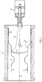
- FIG. 1 schematically shows a section through a closed mold 1.
- a workpiece 2 is shown in its initial shape 3 and with a preformed material supply 4.
- the dot-dash line 5 indicates an axis of symmetry of the workpiece 2 and / or a possible parting plane of the molding tool.
- a gas mixture in the interior of the workpiece 2 is ignited by an ignition device 6.
- a detonation front 7 extends from the ignition device 6 to the opposite end of the molding tool 1 in a propagation direction 11 and impresses the workpiece 2 on a pressure curve 8, which is shown by dashed lines.
- This material deformation zone 9 carries representation technology of the inertia of the material and the time-delayed deformation taking into account.
- the preformed material supply 4 serves to control the material flow in the material-re-forming zone 9.
- the wall thickness and quality of the final shape 10 can be influenced for relevant regions of the workpiece 2.
- the preformed material supply 4 thus oriented favorably in its shape, position and shape on the course of the detonation front 7 and the desired final shape 10.
- the preformed material supply 4 is particularly suitable to the To supply workpiece 2 für spasmanosus, especially areas of large forming work.
- the mold 1 Shown is the mold 1 with constant to the line 5 spaced outer walls and the workpiece 2 with a circumferential riefenartig trained preformed material supply 4.
- This material supply 4 is, as well as the initial shape 3, still spaced from the mold 1.
- the subsequent material-forming zone 9 pushes the material supply 4 in front of it and stores it in the area of the desired greater wall thickness, so that it rests with the initial shape 3 on the outer walls up to the final shape 10.
- the stock of material 4 can serve to form indentations or bulges of the mold 1 in this area.
- FIG. 2 shows various embodiments of the preformed material supply 4 on the workpiece 2.
- FIGS. 2a to 2d and 2f are deformed areas of the material supply 4 to see and in contrast an additionally applied area in Figure 2d .
- Examples of a preformed material supply 4, which may be located outside and / or inside with respect to the forming direction show FIGS. 2a to 2e ,
- the z. B. may be a bump, which is about to be formed simply by a hammer blow from the opposite side.
- FIG. 2b shows a recess 13 of the preformed material supply 4 with respect to the workpiece 2, and thus an approximately linear extension, namely a groove, the z. B. can be folded.
- Figure 2c shows two examples of a fold 14, and thus also a linear extension of the preformed material supply 4.
- Such folds 14 can be achieved by targeted upsetting or multiple folding of the workpiece 2 quickly.
- Figure 2d shows a training example of a wave in the workpiece 2, and thus also an approximately linear extension of the preformed material supply 4 to produce z. B. by rolling, pressing or rolling.
- FIG. 2e shows an embodiment of an additionally applied to the workpiece 2 material portion 16 which forms as a welded sheet the preformed material supply 4 with thicker wall thickness, and depending on the dimensions may be formed about punctiform, linear or planar.
- FIG. 2f shows a stock of material 4 of the workpiece 2, which extends over the circumference of the rotationally symmetrical workpiece 2 here.
- the preformed material supply 4 is formed in this embodiment as two paragraphs 17 and a groove 18.
- a tubular workpiece is shown, but the invention does not limit itself to this basic workpiece shape.
- material stocks may also be pronounced in the opposite direction; z. B. is then from the bulge or bulge 12 to the outside in FIG. 2a a recess or dent to the inside and from the recess or groove 13 to the inside in FIG. 2b an increase or rib to the outside.
- FIG. 3 2 shows a corrugated region 19, composed of corrugations 15, a hardfacing seam 20, a welded-on metal sheet 16 and a respective bulge 12 and dimple 21.
- these are punctual (uniaxial) , linear (biaxial) and planar (three-axis) extensions of the preformed material supply 4.
- a linear expression of several punctual exist and a two-dimensional expression in turn consist of several linear and / or biaxial arranged punctual.
- the preformed material supply 4 may extend longitudinally and transversely to the longitudinal extent of the workpiece. So is the corrugated area 19 z. B. shown along a first possible longitudinal extent 22 and transversely to a second possible longitudinal extension 23 is shown here by way of example a sheet-metal workpiece 2, wherein the shape is also not limited to this basic shape.
Landscapes
- Chemical & Material Sciences (AREA)
- Chemical Kinetics & Catalysis (AREA)
- General Chemical & Material Sciences (AREA)
- Physics & Mathematics (AREA)
- Fluid Mechanics (AREA)
- Engineering & Computer Science (AREA)
- Mechanical Engineering (AREA)
- Shaping Metal By Deep-Drawing, Or The Like (AREA)
Description
- Die vorliegende Erfindung betrifft ein Explosionsumformverfahren mit den oberbegrifflichen Merkmalen von Anspruch 1. Ein gattungsgemäßes Verfahren ist beispielsweise aus der
JP 58 145381 A EP 0 148 459 A ,EP 1 702 695 A ,US 4 788 841 A ,JP 02 17728 A DE 40 35 894 C1 ,DE 33 05 615 A1 , und derGB 878 178 A - Zum Umformen eines Werkstücks existieren unterschiedliche Verfahren. Beim Hydroumformen zum Beispiel wird ein rohrartiges Werkstück mit einer Flüssigkeit, zumeist Wasser, gefüllt und abgedichtet. Durch das Erhöhen des Flüssigkeitsdrucks wird das Werkstück aufgeweitet und legt sich allmählich den Konturen des das Werkstück umgebenden Formwerkzeugs an.
- Ein Explosionsumformverfahren der eingangs genannten Gattung ohne Flüssigkeit ist in der
EP 592 068 - Diese Druckschrift geht auf geläufige Nachteile des Explosionsumformens ein. Aufgrund der auf die Detonation folgenden Schockwelle neigt das Werkstück lokal zur Spannungs- und Rissbildung. Der hohe entstehende Spitzendruck bedingt einen nicht konstanten Materialfluss, was zu unterschiedlichen Wandstärken führen kann. In der
EP 592 068 - In der Praxis hat sich dieser Ansatz nicht durchgesetzt, zum einen weil eine Deflagration weniger prozesssicher ist, und zum anderen weil eben Geschwindigkeit und Umformdruck geringer sind verglichen mit einer Detonation.
- Die der Erfindung zugrundeliegende Aufgabe ist es, einen Explosionsumformprozess der eingangs genannten Gattung dahingehend zu verbessern, dass auf einfache Art und Weise eine gute Qualität des Werkstücks mit gewünschter Wandstärke erzielt werden kann.
- Zur Lösung des oben beschriebenen Problems wird ein Verfahren mit den Merkmalen von Anspruch 1 angegeben. Weitere vorteilhafte Weiterbildungen dieses Verfahrens sind in den Unteransprüchen definiert.
- Dieser Materialvorrat wird durch die Detonation mit umgeformt und kann dazu eingesetzt werden, in gewünschten Bereichen des Werkstücks gewünschte Wandstärken zu erzielen. Durch das Bevorraten von Material kann während des Umformprozesses der Materialfluss über die zur Verfügung stehende Materialmenge verbessert werden. Damit kann ein gleichmäßigeres Ausformen des Werkstücks erzielt werden und dessen Formgebung unterstützt werden. Der vorgeformte Materialvorrat kann also auch dazu dienen, eine gute Wandqualität des Werkstücks herzustellen. In Form, Größe und Lage kann sich der vorgeformte Materialvorrat daher an die Endform des Werkstücks und/oder dem Verlauf der Detonationsfront orientieren.
- Der vorgeformte Materialvorrat kann einen verformten Bereich des Werkstücks aufweisen. Ein solchermaßen vorgeformter Materialvorrat lässt sich leicht durch umformende Formgebung des Werkstücks selbst erreichen und besonders gut an der Werkstück-Endform orientieren.
- Es kann der vorgeformte Materialvorrat über einen zusätzlich an das Werkstück aufgebrachten Materialbereich verfügen. Dieses zusätzlich aufgebrachte Fremdmaterial eignet sich gut für einen klar begrenzten vorgeformten Materialvorrat und kann sehr exakt am Werkstück positioniert werden.
- Vorteilhafterweise besteht der vorgeformte Materialvorrat aus einem Bereich dickerer Wandstärke. Das derart bevorratete Material kann gut von der Detonationsfront erfasst werden und z. B. dem Ausformen von Kavitäten dienen.
- Der vorgeformte Materialvorrat kann außenseitig bezogen auf die Umformrichtung angeordnet sein. Außenseitig kann in diesem Sinn verstanden werden als an der dem Explosionsraum abgewandten Seite des Werkstücks. Ein vorgeformter Materialvorrat an der Außenseite eignet sich besonders dazu, Ausbuchtungen des Werkstücks umzuformen und ist meist gut zugänglich.
- Der vorgeformte Materialvorrat kann innenseitig bezogen auf die Umformrichtung vorgesehen sein. Dies kann sich empfehlen, wenn an der Außenseite engere Toleranzen und bessere Oberflächenqualität als an der Innenseite verlangt werden.
- Es kann von Vorteil sein, den vorgeformten Materialvorrat etwa punktuell auszubilden. Ein solcherart vorgeformter Materialvorrat kann speziell bei kleinen Ein- oder Ausbuchtungen des Formwerkzeugs an dieser Stelle ratsam sein.
- In einer Variation erstreckt sich der vorgeformte Materialvorrat in etwa linear verlaufend. Ein derart vorgeformter Materialvorrat kann sich einachsig erstreckende Formen unterstützen, z. B. Absätze im Formwerkzeug.
- In besonderer Weise kann der vorgeformte Materialvorrat etwa flächig ausgebildet sein. Eine flächige Ausbildung kann z. B. von Vorteil sein, einen ausgedehnten Bereich größerer Wandstärke auszuformen. Sie kann sich auch aus punktuellen und/oder linearen Ausbildungen zusammensetzen, mit deren genannten Vorteilen.
- Der vorgeformte Materialvorrat kann aus mindestens einer Ein- und/oder Ausbuchtung und/oder Vertiefung und/oder Erhöhung in der Werkstückwand bestehen. In einer weiteren günstigen Ausführungsform besteht der vorgeformte Materialvorrat aus mindestens einer Riefe und/oder Rippe und/oder Falte und/oder Welle und/oder einem Absatz und/oder einer Nut. Abhängig von der Werkstück-Endform bzw. der Kavität des Formwerkzeugs lässt sich mit solchen Formen des vorgeformten Materialvorrats, die in der Praxis leicht aufbringbar sind, der Umformvorgang an kritischen Bereichen in gewünschter Weise beeinflussen.
- Vorteilhafterweise kann der vorgeformte Materialvorrat quer zur Längserstreckung des Werkstücks verlaufend ausgebildet sein. Diese Ausführung empfiehlt sich insbesondere, wenn die Umformarbeit quer zur Längserstreckung des Werkstücks groß ist.
- In einer Abwandlung ist der vorgeformte Materialvorrat längs bezüglich der Längserstreckung des Werkstücks ausgebildet. Diese Abwandlung ist dann empfehlenswert, wenn die Umformarbeit in dieser Richtung groß ist.
- Der vorgeformte Materialvorrat kann sich über den Umfang des Werkstücks erstrecken. Ein dergestalt vorgeformter Materialvorrat kann der Umformung von Werkstücken mit rohrförmigen Abschnitten dienen.
- Dieser vorgeformte Materialvorrat wird beim Explosionsumformen genutzt und erhöht die für die Umformung zur Verfügung stehende Materialmenge lokal, was zur Verbesserung des Materialflusses eingesetzt werden kann. Das derart bevorratete Material kann an relevanten Bereichen wieder abgelagert werden, um dort die gewünschte Form oder Wandstärke zu erreichen. In der Praxis kann der vorgeformte Materialvorrat ebenso einfach wie kostengünstig durch bekannte Verfahren am Werkstück ausgebildet werden, beispielsweise durch Umformen und thermisches Fügen.
- Vorteilhafterweise kann der vorgeformte Materialvorrat durch Verformen eines Bereiches des Werkstücks hergestellt werden. Diese Verformung kann leicht durch umformende Formgebung erreicht werden, z. B. durch Quetschen, Biegen oder auch Rollieren, und kann ohne großen Aufwand und ohne große Kosten in die Verfahrenskette integriert werden.
- Der vorgeformte Materialvorrat kann durch Aufbringung zusätzlichen Materials an das Werkstück hergestellt werden. Dieser aufgebrachte Materialbereich kann schnell, z. B. durch Auftragsschweißen oder Anschweißen zusätzlichen Materials erzeugt werden, und der Verfahrensschritt lässt sich ebenfalls einfach und kostengünstig in den Herstellungsprozess des Werkstücks integrieren.
- In besonderer Weise kann der vorgeformte Materialvorrat vor dem Einbringen des Werkstücks in das Formwerkzeug ausgebildet werden. Damit kann der Materialvorrat separat ausgebildet und das Formwerkzeug auf den Explosionsumformvorgang hin optimiert werden.
- Im folgenden wird ein Ausführungsbeispiel der Erfindung anhand der Zeichnung beschrieben. Dabei zeigen:
- Figur 1
- schematisch das Prinzip der Erfindung anhand eines Schnittes durch das Formwerkzeug und das Werkstück mit vorgeformtem Materialvorrat,
- Figur 2
- Varianten des erfindungsgemäß vorgeformten Materialvorrats anhand von Werkstückschnitten, wobei in
- Figur 2a
- eine Ein- bzw. Ausbuchtung,
- Figur 2b
- eine Riefe bzw. Rippe,
- Figur 2c
- verschiedene Falten,
- Figur 2d
- eine Welle,
- Figur 2e
- ein zusätzlich aufgebrachter Materialbereich und
- Figur 2f
- eine Nut und zwei Absätze dargestellt ist bzw. sind, und
- Figur 3
- Varianten von erfindungsgemäß vorgeformten Materialvorräten, speziell punktuelle, lineare und flächige Ausprägungen.
- Gleiche Bezugszeichen verweisen auf gleiche Teile bzw. Merkmale, unabhängig von der Figur.
-
Figur 1 zeigt schematisch einen Schnitt durch ein geschlossenes Formwerkzeug 1. In diesem ist ein Werkstück 2 in seiner Ausgangsgestalt 3 und mit einen vorgeformten Materialvorrat 4 dargestellt. Die strichpunktierte Linie 5 deutet eine Symmetrieachse des Werkstücks 2 und/oder eine mögliche Trennebene des Formwerkzeugs an. - Ein Gasgemisch im Inneren des Werkstücks 2 wird durch eine Zündeinrichtung 6 gezündet. Eine Detonationsfront 7 verläuft von der Zündeinrichtung 6 zum entgegengesetzten Ende des Formwerkzeugs 1 in eine Ausbreitungsrichtung 11 und prägt dem Werkstück 2 einen Druckverlauf 8 auf, der strichliniert dargestellt ist.
- Die eigentliche Umformung geschieht in einer mit 9 gekennzeichneten Zone, die der Detonationsfront 7 mit kurzer zeitlicher Verzögerung folgt und eine Endgestalt 10 des Werkstücks 2 ausprägt. Diese Materialumformungszone 9 trägt darstellungstechnisch der Trägheit des Materials und der damit zeitlich verzögerten Umformung Rechnung.
- Während des Umformprozesses dient der vorgeformte Materialvorrat 4 dem Steuern des Materialflusses in der Materialumfornungszone 9. Durch die Materialbevorratung kann für relevante Bereiche des Werkstücks 2 die Wandungsstärke und -qualität der Endgestalt 10 beeinflusst werden. Der vorgeformte Materialvorrat 4 orientiert sich also günstigerweise in seiner Form, Lage und Gestalt am Verlauf der Detonationsfront 7 sowie an der gewünschten Endgestalt 10. Weiterhin eignet sich der vorgeformte Materialvorrat 4 besonders dazu, dem Werkstück 2 aufzuprägende Formen des Formwerkzeugs 1 während des Umformprozesses mit zusätzlichem Material zu versorgen, besonders Bereiche großer Umformarbeit.
- Dargestellt ist das Formwerkzeug 1 mit konstant zu der Linie 5 beabstandeten Außenwänden und das Werkstück 2 mit einem umlaufend riefenartig ausgebildeten vorgeformten Materialvorrat 4. Dieser Materialvorrat 4 ist, ebenso wie die Ausgangsgestalt 3, noch vom Formwerkzeug 1 beabstandet. Durch Einwirkung der Detonationsfront 7 schiebt die nachfolgende Materialumformungszone 9 den Materialvorrat 4 vor sich her und lagert ihn umgeformt im Bereich gewünschter größerer Wandstärke ab, so dass er sich mit der Ausgangsgestalt 3 an die Außenwände bis zur Endgestalt 10 anlegt. Genauso gut kann der Materialvorrat 4 dazu dienen, Ein- oder Ausbuchtungen des Formwerkzeugs 1 in diesem Bereich auszuformen.
-
Figur 2 zeigt verschiedene Ausführungsformen des vorgeformten Materialvorrats 4 am Werkstück 2. InFigur 2a bis 2d und 2f sind verformte Bereiche des Materialvorrats 4 zu sehen und im Gegensatz dazu ein zusätzlich aufgebrachter Bereich inFigur 2d . Beispiele für einen vorgeformten Materialvorrat 4, welcher sich außen- und/oder innenseitig bezogen auf die Umformrichtung befinden kann, zeigenFigur 2a bis 2e . - Dabei zeigt
Figur 2a eine Ausbuchtung 12 und damit eine etwa punktuelle Ausprägung des vorgeformten Materialvorrats 4. Das kann z. B. eine Beule sein, welche etwa einfach durch einen Hammerschlag von der Gegenseite her auszubilden ist. -
Figur 2b zeigt eine Vertiefung 13 des vorgeformten Materialvorrats 4 bezüglich des Werkstücks 2, und damit eine etwa lineare Erstreckung, namentlich eine Riefe, die z. B. gefalzt werden kann. -
Figur 2c zeigt zwei Beispiele einer Falte 14, und damit ebenfalls eine lineare Erstreckung des vorgeformten Materialvorrats 4. Derartige Falten 14 können durch gezieltes Stauchen oder Mehrfachfalzen des Werkstücks 2 schnell erzielt werden. -
Figur 2d zeigt ein Ausbildungsbeispiel einer Welle im Werkstück 2, und damit ebenfalls eine etwa lineare Erstreckung des vorgeformten Materialvorrats 4, herzustellen z. B. durch Walzen, Pressen oder Rollieren. -
Figur 2e zeigt ein Ausführungsbeispiel eines zusätzlich an das Werkstück 2 aufgebrachten Materialbereichs 16, der als aufgeschweißtes Blech den vorgeformten Materialvorrat 4 mit dickerer Wandstärke bildet, und je nach Abmessungen etwa punktuell, linear verlaufend oder flächig ausgebildet sein kann. -
Figur 2f zeigt einen Materialvorrat 4 des Werkstücks 2, welcher sich über den Umfang des hier rotationssymmetrischen Werkstücks 2 erstreckt. Der vorgeformte Materialvorrat 4 ist in diesem Ausführungsbeispiel als zwei Absätze 17 und eine Nut 18 ausgeformt. In dieser Teilfigur ist ein rohrförmiges Werkstück gezeigt, wobei sich die Erfindung jedoch nicht auf diese Werkstück-Grundform einschränkt. - Die in
Figur 2 dargestellten Materialvorräte können ebenso in die Gegenrichtung ausgeprägt sein; z. B. wird dann aus der Ausbuchtung bzw. Beule 12 zur Außenseite inFigur 2a eine Einbuchtung bzw. Delle zur Innenseite und aus der Vertiefung bzw. Riefe 13 zur Innenseite inFigur 2b eine Erhöhung bzw. Rippe zur Außenseite. -
Figur 3 zeigt weitere Ausführungsbeispiele zur Ausprägung des vorgeformten Materialvorrats 4 am Werkstück 2. Zu sehen ist ein gewellter Bereich 19, aus Wellen 15 zusammengesetzt, eine Auftragsschweißnaht 20, ein aufgeschweißtes Blech 16 und je eine Beule 12 und Delle 21. Namentlich sind dies punktuelle (einachsige), lineare (zweiachsige) sowie flächige (dreiachsige) Erstreckungen des vorgeformten Materialvorrats 4. Dabei kann eine lineare Ausprägungsart aus mehreren punktuellen bestehen und eine flächige Ausprägungsart ihrerseits wiederum aus mehreren linearen und/oder zweiachsig angeordneten punktuellen. Der vorgeformte Materialvorrat 4 kann sich längs sowie quer zur Längserstreckung des Werkstücks erstrecken. So befindet sich der gewellte Bereich 19 z. B. längs zu einer ersten möglichen Längserstreckung 22 und quer zu einer zweiten möglichen Längserstreckung 23. Dargestellt ist hier beispielhaft ein blechförmiges Werkstück 2, wobei dessen Form ebenfalls nicht auf diese Grundform beschränkt sein soll.
Claims (12)
- Explosionsumformverfahren,
bei welchem ein Werkstück (2) in ein Formwerkzeug (1) eingebracht und dort von einer Ausgangsgestalt (3) mittels Explosionsumformens zu einer Endgestalt (10) umgeformt wird, wobei ein Gasgemisch von einer Zündeinrichtung (6) gezündet wird,
dadurch gekennzeichnet,
dass die Ausgangsgestalt (3) des Werkstücks (2) mit wenigstens einem gegenüber benachbarten Bereichen vorgeformten Materialvorrat (4) versehen wird und durch die Zündung des Gasgemisches eine Detonationsfront (7) erzeugt wird, welche von der Zündeinrichtung (6) zu einem entgegengesetzten Ende des Formwerkzeugs (2) verläuft und den Materialvorrat (4) mit umformt. - Verfahren nach Anspruch 1,
dadurch gekennzeichnet,
dass der vorgeformte Materialvorrat (4) durch Verformen eines Bereiches des Werkstücks (2) hergestellt wird. - Verfahren nach Anspruch 1 oder 2,
dadurch gekennzeichnet,
dass der vorgeformte Materialvorrat (4) durch Aufbringen zusätzlichen Materials an das Werkstück (2) hergestellt wird. - Verfahren nach mindestens einem vorhergehenden Anspruch 1 bis 3,
dadurch gekennzeichnet,
dass der vorgeformte Materialvorrat (4) vor dem Einbringen des Werkstücks (2) in das Formwerkzeug (1) ausgebildet wird. - Explosionsumformverfahren nach mindestens einem vorhergehenden Anspruch,
dadurch gekennzeichnet,
dass der vorgeformte Materialvorrat (4) durch Ausbilden eines Bereichs dickerer Wandstärke hergestellt wird. - Explosionsumformverfahren nach mindestens einem vorhergehenden Anspruch,
dadurch gekennzeichnet,
dass der vorgeformte Materialvorrat (4) außenseitig bezogen auf die Umformrichtung angeordnet wird. - Explosionsumformverfahren nach mindestens einem vorhergehenden Anspruch,
dadurch gekennzeichnet,
dass der vorgeformte Materialvorrat (4) innenseitig bezogen auf die Umformrichtung angeordnet, oder etwa punktuell ausgebildet oder etwa flächig ausgebildet wird, oder etwa linear verlaufend angeordnet wird. - Explosionsumformverfahren nach mindestens einem vorhergehenden Anspruch,
dadurch gekennzeichnet,
dass der vorgeformte Materialvorrat (4) als mindestens ein(e) Ein- und/oder Ausbuchtung und/oder Vertiefung und/oder Erhöhung in der Werkstückwand ausgebildet wird. - Explosionsumformverfahren nach mindestens einem vorhergehenden Anspruch,
dadurch gekennzeichnet,
dass der vorgeformte Materialvorrat (4) als mindestens ein(e) Riefe und/oder Rippe und/oder Falte und/oder Welle und/oder Absatz und/oder Nut ausgebildet wird. - Explosionsumformverfahren nach mindestens einem vorhergehenden Anspruch,
dadurch gekennzeichnet,
dass der vorgeformte Materialvorrat (4) bezüglich der Längserstreckung des Werkstücks (2) quer dazu verlaufend ausgebildet wird. - Explosionsumformverfahren nach mindestens einem vorhergehenden Anspruch,
dadurch gekennzeichnet,
dass der vorgeformte Materialvorrat (4) bezüglich der Längserstreckung des Werkstücks (2) längs dazu verlaufend ausgebildet wird. - Explosionsumformverfahren nach mindestens einem vorhergehenden Anspruch,
dadurch gekennzeichnet,
dass der vorgeformte Materialvorrat (4) über den Umfang des Werkstücks (2) ausgebildet wird.
Applications Claiming Priority (2)
| Application Number | Priority Date | Filing Date | Title |
|---|---|---|---|
| DE102006060372A DE102006060372A1 (de) | 2006-12-20 | 2006-12-20 | Werkstück und Verfahren für das Explosionsumformen |
| PCT/EP2007/010632 WO2008080502A1 (de) | 2006-12-20 | 2007-12-06 | Werkstück und verfahren für das explosionsumformen |
Publications (2)
| Publication Number | Publication Date |
|---|---|
| EP2101935A1 EP2101935A1 (de) | 2009-09-23 |
| EP2101935B1 true EP2101935B1 (de) | 2019-02-27 |
Family
ID=39032318
Family Applications (1)
| Application Number | Title | Priority Date | Filing Date |
|---|---|---|---|
| EP07856437.4A Not-in-force EP2101935B1 (de) | 2006-12-20 | 2007-12-06 | Werkstück und verfahren für das explosionsumformen |
Country Status (4)
| Country | Link |
|---|---|
| US (1) | US8322175B2 (de) |
| EP (1) | EP2101935B1 (de) |
| DE (1) | DE102006060372A1 (de) |
| WO (1) | WO2008080502A1 (de) |
Families Citing this family (24)
| Publication number | Priority date | Publication date | Assignee | Title |
|---|---|---|---|---|
| DE102005025660B4 (de) | 2005-06-03 | 2015-10-15 | Cosma Engineering Europe Ag | Vorrichtung und Verfahren zum Explosionsumformen |
| DE102006037754B3 (de) | 2006-08-11 | 2008-01-24 | Cosma Engineering Europe Ag | Verfahren und Vorrichtung zum Explosionsumformen |
| DE102006037742B4 (de) | 2006-08-11 | 2010-12-09 | Cosma Engineering Europe Ag | Verfahren und Vorrichtung zum Explosionsumformen |
| DE102006056788B4 (de) | 2006-12-01 | 2013-10-10 | Cosma Engineering Europe Ag | Verschlusseinrichtung für das Explosionsumformen |
| DE102006060372A1 (de) | 2006-12-20 | 2008-06-26 | Cosma Engineering Europe Ag | Werkstück und Verfahren für das Explosionsumformen |
| DE102007007330A1 (de) | 2007-02-14 | 2008-08-21 | Cosma Engineering Europe Ag | Verfahren und Werkzeuganordnung zum Explosionsumformen |
| DE102007023669B4 (de) | 2007-05-22 | 2010-12-02 | Cosma Engineering Europe Ag | Zündeinrichtung für das Explosionsumformen |
| DE102007036196A1 (de) | 2007-08-02 | 2009-02-05 | Cosma Engineering Europe Ag | Vorrichtung für die Zufuhr eines Fluids für Explosionsumformen |
| DE102008006979A1 (de) | 2008-01-31 | 2009-08-06 | Cosma Engineering Europe Ag | Vorrichtung für das Explosionsumformen |
| US9587871B2 (en) | 2012-05-03 | 2017-03-07 | Whirlpool Corporation | Heater-less ice maker assembly with a twistable tray |
| US9513045B2 (en) | 2012-05-03 | 2016-12-06 | Whirlpool Corporation | Heater-less ice maker assembly with a twistable tray |
| US8925335B2 (en) | 2012-11-16 | 2015-01-06 | Whirlpool Corporation | Ice cube release and rapid freeze using fluid exchange apparatus and methods |
| US9273891B2 (en) | 2012-12-13 | 2016-03-01 | Whirlpool Corporation | Rotational ice maker |
| US9518770B2 (en) | 2012-12-13 | 2016-12-13 | Whirlpool Corporation | Multi-sheet spherical ice making |
| US9476629B2 (en) | 2012-12-13 | 2016-10-25 | Whirlpool Corporation | Clear ice maker and method for forming clear ice |
| US9557087B2 (en) | 2012-12-13 | 2017-01-31 | Whirlpool Corporation | Clear ice making apparatus having an oscillation frequency and angle |
| US9500398B2 (en) | 2012-12-13 | 2016-11-22 | Whirlpool Corporation | Twist harvest ice geometry |
| US9310115B2 (en) | 2012-12-13 | 2016-04-12 | Whirlpool Corporation | Layering of low thermal conductive material on metal tray |
| US9410723B2 (en) | 2012-12-13 | 2016-08-09 | Whirlpool Corporation | Ice maker with rocking cold plate |
| US9518773B2 (en) | 2012-12-13 | 2016-12-13 | Whirlpool Corporation | Clear ice maker |
| US9470448B2 (en) | 2012-12-13 | 2016-10-18 | Whirlpool Corporation | Apparatus to warm plastic side of mold |
| WO2016065269A2 (en) | 2014-10-23 | 2016-04-28 | Whirlpool Corporation | Method and apparatus for increasing rate of ice production in an automatic ice maker |
| US10739053B2 (en) | 2017-11-13 | 2020-08-11 | Whirlpool Corporation | Ice-making appliance |
| US10907874B2 (en) | 2018-10-22 | 2021-02-02 | Whirlpool Corporation | Ice maker downspout |
Family Cites Families (107)
| Publication number | Priority date | Publication date | Assignee | Title |
|---|---|---|---|---|
| DE1452667U (de) | ||||
| US392635A (en) | 1888-11-13 | powers | ||
| US1280451A (en) | 1917-02-02 | 1918-10-01 | William F Hagen | Valve. |
| GB742460A (en) | 1952-06-11 | 1955-12-30 | Union Carbide & Carbon Corp | Sheet metal forming by use of detonation waves |
| GB878178A (en) * | 1959-12-01 | 1961-09-27 | Olin Mathieson | Metal forming |
| US3131661A (en) * | 1960-04-20 | 1964-05-05 | Smith Corp A O | Explosive forming of articles |
| DE1129562B (de) | 1961-04-21 | 1962-05-17 | Telefonbau | Schaltungsanordnung zur Gebuehrenerfassung mit Gespraechszetteldrucker im internationalen Fernwahlbetrieb |
| US3206963A (en) * | 1962-04-04 | 1965-09-21 | Martin Marietta Corp | Method and apparatus for explosive forming of metal articles |
| US3252312A (en) | 1962-04-25 | 1966-05-24 | Continental Can Co | Method and apparatus for explosive reshaping of hollow ductile objects |
| US3160949A (en) | 1962-05-21 | 1964-12-15 | Aerojet General Co | Method of joining elongated objects |
| DE1235246B (de) | 1962-07-17 | 1967-03-02 | Wmf Wuerttemberg Metallwaren | Vorrichtung zur Hochenergieformung, insbesondere zur Explosionsumformung von Metallblechen od. dgl. |
| CH409831A (de) | 1962-08-28 | 1966-03-31 | Josef Schaberger & Co G M B H | Vorrichtung zur Verformung von Körpern durch Explosion |
| FR1342377A (fr) | 1962-10-17 | 1963-11-08 | Continental Can Co | Procédé et dispositif de refaçonnage par explosion d'objets creux ductiles |
| DE1218986B (de) | 1962-12-21 | 1966-06-16 | Wmf Wuerttemberg Metallwaren | Verfahen und Platine zur Herstellung von Hohlkoerpern oder aehnlichen Formteilen ausBlech durch Hochenergieumformung |
| AT248838B (de) | 1963-11-19 | 1966-08-25 | Wmf Wuerttemberg Metallwaren | Verfahren und Werkzeug zur Herstellung von Werkstücken durch Hochenergieformung |
| US3342048A (en) | 1964-08-13 | 1967-09-19 | Gen Am Transport | Detonation wave forming machine |
| US3338080A (en) | 1964-09-21 | 1967-08-29 | Gen Dynamics Corp | Forming apparatus |
| DE1527949A1 (de) | 1965-01-19 | 1969-11-20 | Chemokomplex Vegyipari Gep Es | Verfahren und Einrichtung zur Ausbildung von gewoelbten Schalen aus Metallplatten |
| DE1452667A1 (de) | 1965-09-30 | 1969-03-06 | Gen American Transp Corp | Maschine zum plastischen Verformen mittels Detonationswellen |
| GB1129562A (en) | 1966-03-07 | 1968-10-09 | Vickers Ltd | The generation of shock waves by exploding wire methods |
| GB1280451A (en) | 1968-05-02 | 1972-07-05 | Int Research & Dev Co Ltd | Improvements in and relating to methods of explosively welding tubes into tube plates |
| AT299664B (de) | 1968-05-17 | 1972-06-26 | Boehler & Co Ag Geb | Vorrichtung zur Explosionverformung metallischer Werkstoffe |
| DE1777207A1 (de) | 1968-09-25 | 1971-04-01 | Hertel Heinrich Prof Dr Ing | Vorrichtung zur Hochleistungsumformung von Werkstuecken,insbesondere aus Blech,mit Hilfe von Schockwirkungsmitteln |
| DE1777208A1 (de) | 1968-09-25 | 1971-04-01 | Hertel Heinrich Prof Dr Ing | Vorrichtung zur Hochleistungsumformung von Werkstuecken,insbesondere aus Blech,mit Hilfe von Schockwirkungsmitteln |
| DE1801784A1 (de) | 1968-10-08 | 1970-06-11 | Bbc Brown Boveri & Cie | Arbeitsfunkenstrecke zur Erzeugung von Druckwellen in einem isolierenden,fluessigen Medium |
| DE1808942A1 (de) | 1968-11-14 | 1970-06-11 | Rune Hank | Verfahren zur Explosionsumformung |
| DE1809866B2 (de) * | 1968-11-15 | 1972-04-20 | Hertel, Heinrich, Prof Dr Ing E h Dr Ing , 1000 Berlin | Verfahren zur herstellung von erosions-elektroden durch umformen von blech in einem dem elektrodennegativ entsprechenden gesenk |
| US3654788A (en) | 1968-11-20 | 1972-04-11 | Lead Metal Kogyo Kk | Method of discharge forming bulged articles |
| US3640110A (en) | 1969-08-14 | 1972-02-08 | Inoue K | Shock forming |
| US3661004A (en) | 1969-11-07 | 1972-05-09 | Atlas Chem Ind | Explosive tubing swager |
| US3737975A (en) | 1970-07-15 | 1973-06-12 | Kinnon C Mc | Arrangement for explosively formed connections and method of making such connections |
| DE2043251A1 (en) | 1970-09-01 | 1972-03-02 | Nydamit Nobel Ag | Explosive forming - by shock wave conducted into the workpiece from outside |
| US3712022A (en) * | 1970-11-02 | 1973-01-23 | Continental Can Co | Shock wave application of twist-off crowns |
| DE2059181C3 (de) | 1970-12-02 | 1975-02-27 | Messwandler-Bau Gmbh, 8600 Bamberg | Anordnung zur Hochdruck-Energieumformung von Körpern |
| US3742746A (en) | 1971-01-04 | 1973-07-03 | Continental Can Co | Electrohydraulic plus fuel detonation explosive forming |
| DE2107460A1 (en) | 1971-02-17 | 1972-08-31 | Mylaeus Geb | Internally expanding pipes - to centrally increase their buckling strength |
| GB1436538A (en) | 1972-11-17 | 1976-05-19 | Dale Ltd John | Manufacture of articles such as collapsible tubes |
| DE2337176C3 (de) | 1973-07-21 | 1981-08-06 | Tokyu Sharyo Seizo K.K., Yokohama, Kanagawa | Vorrichtung zum Hochgeschwindigkeitsumformen vom metallischen rohrförmigen Werkstücken in einer mehrteiligen Formkammer |
| GB1419889A (en) | 1973-12-21 | 1975-12-31 | Kh Aviatsionnyj Institut | Plant for explosive forming |
| ZA754574B (en) | 1974-07-29 | 1976-06-30 | Concast Inc | A method of forming the walls of continuous casting and chill |
| DD114231A1 (de) | 1974-08-29 | 1975-07-20 | ||
| FR2300322A1 (fr) | 1975-02-04 | 1976-09-03 | Poudres & Explosifs Ste Nale | Systeme de mise a feu pour charges explosives immergees |
| SU575161A1 (ru) | 1975-05-11 | 1977-10-05 | Физико-технический институт АН Белорусской ССР | Устройство дл штамповки листовых заготовок жидкостью высокого давлени |
| GB1482978A (en) | 1975-06-27 | 1977-08-17 | Ici Ltd | Expanding metal tubes |
| DE2628579C2 (de) | 1976-06-25 | 1983-02-17 | Fiziko-techničeskij institut Akademii Nauk Belorusskoj SSR, Minsk | Vorrichtung zum elektrohydraulischen Explosionsumformen |
| GB1542519A (en) | 1976-07-07 | 1979-03-21 | Fiz Tekh I An Brus Ssr | Electrical discharge forming devices |
| US4187709A (en) | 1976-08-23 | 1980-02-12 | Kevin Strickland | Explosive forming |
| DE2754666A1 (de) | 1977-12-08 | 1979-06-13 | Hinapat Ag | Verfahren und vorrichtung zur herstellung eines tubenrohlings |
| DD135859A1 (de) | 1978-04-24 | 1979-06-06 | Heinz Heinrich | Verfahren zum zuenden von sprengstoff in explosivumformanlagen |
| GB2047147B (en) | 1979-04-06 | 1982-12-08 | Ukrain Nii Protezirova Protez | Manufacturing sockets for extremity prosthesis |
| DE3012342C2 (de) | 1980-03-29 | 1984-08-16 | Scheuch Folien- und Papierverarbeitung GmbH & Co KG, 6109 Mühltal | Mehrschichtfolie und Verfahren zum Verschluß von Gefäßen |
| AT371384B (de) | 1980-08-08 | 1983-06-27 | Uk Nii Protezirovania Protezos | Verfahren zum umformen eines werkstueckes durch impulsbelastung, gaskanone zur durchfuehrung des verfahrens sowie umformeinrichtung zum umformen von werkstuecken durch impulsbelastung mit einer solchen gaskanone |
| DD158364B1 (de) | 1981-04-09 | 1986-03-12 | Germania Chemnitz | Schutzvorrichtung zur explosivbearbeitung von bauteilen |
| BG34210A1 (en) | 1981-07-15 | 1983-08-15 | Kortenski | Machine for explosive forming |
| US4492104A (en) | 1981-12-02 | 1985-01-08 | Meadowcraft Inc. | Explosive shaping of metal tubing |
| JPS58145381A (ja) * | 1982-02-23 | 1983-08-30 | Mitsubishi Heavy Ind Ltd | クラツド鋼管の製造方法 |
| US4494392A (en) | 1982-11-19 | 1985-01-22 | Foster Wheeler Energy Corporation | Apparatus for forming an explosively expanded tube-tube sheet joint including a low energy transfer cord and booster |
| DE3305615C2 (de) * | 1983-02-18 | 1986-10-16 | Heinrich Dr.-Ing. 4290 Bocholt Hampel | Anordnung zum Befestigen eines Rohres in einer Lochplatte mittels Explosionsdruckwellen |
| US4571800A (en) | 1983-07-11 | 1986-02-25 | Thiokol Corporation | Method for explosively forming an auxiliary exit cone for the nozzle of a rocket motor |
| DD217154A1 (de) | 1983-09-06 | 1985-01-09 | Komb Pumpen U Verdichter Wtz V | Verfahren und vorrichtung zum warmexplosivumformen von blechhohlteilen |
| DE3347319A1 (de) * | 1983-12-28 | 1985-07-11 | Kraftwerk Union AG, 4330 Mülheim | Einrichtung zum schweissplattieren von rohren |
| DE3581293D1 (de) | 1984-02-09 | 1991-02-21 | Toyota Motor Co Ltd | Verfahren zur herstellung von ultrafeinen keramikpartikeln. |
| SU1181331A1 (ru) | 1984-06-05 | 1989-10-23 | Научно-исследовательский институт технологии автомобильной промышленности | Установка дл детонационного напылени |
| DE3512015A1 (de) | 1985-04-02 | 1986-10-02 | Robert Bosch Gmbh, 7000 Stuttgart | Vorrichtung zur behandlung von werkstuecken mittels temperatur- und druckstoessen durch zuenden eines brennbaren gasgemisches, insbesondere thermische entgratanlage |
| US4738012A (en) | 1985-12-31 | 1988-04-19 | Hughes Robert W | Method of making a cam shaft |
| DE3709181A1 (de) | 1987-03-20 | 1988-09-29 | Asea Ab | Verfahren zur herstellung von komplizierten blechteilen und werkzeug fuer die druckumformung solcher blechteile |
| DD260450A1 (de) | 1987-04-09 | 1988-09-28 | Pk Byuro Elektrogidravliki An | Verfahren und vorrichtung zum einpressen von rohren durch elektrische zuendung |
| US4856311A (en) | 1987-06-11 | 1989-08-15 | Vital Force, Inc. | Apparatus and method for the rapid attainment of high hydrostatic pressures and concurrent delivery to a workpiece |
| US4788841A (en) * | 1987-11-18 | 1988-12-06 | Aluminum Company Of America | Method and apparatus for making step wall tubing |
| JPH02117728A (ja) * | 1988-10-25 | 1990-05-02 | Sumitomo Metal Ind Ltd | 外面2条ひれ付管の製造装置 |
| GB8918552D0 (en) | 1989-08-15 | 1989-09-27 | Alford Sidney C | Flexible linear explosive cutting or fracturing charge |
| DE4035894C1 (en) | 1990-11-12 | 1992-01-30 | Hampel, Heinrich, Dr., Moresnet, Be | Cooling box for blast furnaces with low mfr. cost - produced from cooling pipe preformed with number bends and explosively welded |
| US5256430A (en) | 1991-05-29 | 1993-10-26 | Nkk Corporation | Method for generating a detonation pressure |
| GB9114444D0 (en) | 1991-07-04 | 1991-08-21 | Cmb Foodcan Plc | Apparatus and method for reshaping containers |
| US5220727A (en) | 1992-06-25 | 1993-06-22 | Hochstein Peter A | Method making cam shafts |
| DE4232913C2 (de) | 1992-10-01 | 1995-04-27 | Daimler Benz Ag | Zweistufiges Verfahren zum hydromechanischen explosionsunterstützen Tiefziehen von Blech und Tiefziehpresse zur Durchführung des Verfahrens |
| DE19536292C2 (de) | 1995-09-29 | 1997-09-25 | Leinemann Gmbh & Co | Verfahren und Vorrichtung zum Abschwächen einer Detonation in einem Behälter- bzw. Rohrleitungssystem |
| DE19638679A1 (de) | 1996-09-20 | 1998-03-26 | Schmalbach Lubeca | Verschlußvorrichtung für Einrichtung zum Expansionsformen mit lanzenförmigem Stopfen |
| DE19638688A1 (de) | 1996-09-20 | 1998-03-26 | Schmalbach Lubeca | Verschlußvorrichtung für Einrichtung zum Expansionsformen mit konischem Stopfen |
| EP0830907A3 (de) | 1996-09-20 | 1998-09-23 | Schmalbach-Lubeca AG | Verschlussvorrichtung für eine Einrichtung zum Expansionsformen |
| DE19638678A1 (de) | 1996-09-20 | 1998-03-26 | Schmalbach Lubeca | Verschlußvorrichtung für eine Einrichtung zum Expansionsformen |
| DE19709918C2 (de) | 1997-03-11 | 2001-02-01 | Dornier Medizintechnik | Hochleistungs-Druckwellenquelle |
| US5890698A (en) | 1997-10-13 | 1999-04-06 | Domytrak; Walter | Valve having pressure equalizing conduit |
| IL122795A (en) | 1997-12-29 | 2002-02-10 | Pulsar Welding Ltd | Combined pulsed magnetic and pulsed discharge forming of a dish from a planar plate |
| DE19818572C1 (de) | 1998-04-25 | 1999-11-11 | Leinemann Gmbh & Co | Verfahren zum Unschädlichmachen einer Detonationsfront und Detonationssicherung |
| SE518722C2 (sv) | 1998-06-26 | 2002-11-12 | Flow Holdings Gmbh Sagl Llc | Anordning och förfarande för expansionsformning |
| DE19852302A1 (de) | 1998-11-12 | 2000-05-25 | Fraunhofer Ges Forschung | Verfahren und Vorrichtung zum Bearbeiten von Werkstücken mit Hochenergiestrahlung |
| DE19915383B4 (de) * | 1999-04-06 | 2004-07-22 | Amborn, Peter, Dr.-Ing. | Hydroformverfahren |
| JP4421021B2 (ja) | 1999-08-19 | 2010-02-24 | 株式会社ディスコ | 放電成形ユニット及び切削装置 |
| DE19957836B4 (de) | 1999-11-25 | 2004-05-27 | RMG - Gaselan Regel + Meßtechnik GmbH | Verfahren und Vorrichtung zum Dämpfen des Druckstoßes an Flammensperren bei Detonationen |
| JP2002093379A (ja) | 2000-09-14 | 2002-03-29 | Matsushita Electric Ind Co Ltd | 放電形成デバイス、放電発光デバイス、プラズマディスプレイパネル、並びにそれらを用いた照明装置及びディスプレイ装置 |
| US7093470B2 (en) | 2002-09-24 | 2006-08-22 | The Boeing Company | Methods of making integrally stiffened axial load carrying skin panels for primary aircraft structure and fuel tank structures |
| DE10328154A1 (de) | 2003-06-07 | 2004-12-23 | Günter Volland | Bombenschutzbehälter |
| US7296449B2 (en) | 2004-09-21 | 2007-11-20 | Ball Corporation | Dry hydraulic can shaping |
| DE102005012475A1 (de) * | 2005-03-16 | 2006-09-21 | IFUTEC Ingenieurbüro für Umformtechnik GmbH | Verfahren zur Herstellung eines Übergangs an einem Hohlformteil |
| DE102005025660B4 (de) | 2005-06-03 | 2015-10-15 | Cosma Engineering Europe Ag | Vorrichtung und Verfahren zum Explosionsumformen |
| DE102006008533A1 (de) | 2006-02-22 | 2007-08-30 | Rheinisch-Westfälisch-Technische Hochschule Aachen | Verfahren und Vorrichtung zur Gestaltung eines Druckprofils bei einer Detonationsumformung |
| JP2007222778A (ja) | 2006-02-23 | 2007-09-06 | Toto Ltd | 放電生成ガス溶解装置 |
| DE102006019856A1 (de) | 2006-04-28 | 2007-11-08 | Admedes Schuessler Gmbh | Verfahren zum Bearbeiten von Werkstoffen unter Verwendung von porösem Silizium als Sprengstoff |
| DE102006037754B3 (de) | 2006-08-11 | 2008-01-24 | Cosma Engineering Europe Ag | Verfahren und Vorrichtung zum Explosionsumformen |
| DE102006037742B4 (de) | 2006-08-11 | 2010-12-09 | Cosma Engineering Europe Ag | Verfahren und Vorrichtung zum Explosionsumformen |
| DE102006056788B4 (de) | 2006-12-01 | 2013-10-10 | Cosma Engineering Europe Ag | Verschlusseinrichtung für das Explosionsumformen |
| DE102006060372A1 (de) | 2006-12-20 | 2008-06-26 | Cosma Engineering Europe Ag | Werkstück und Verfahren für das Explosionsumformen |
| DE102007007330A1 (de) | 2007-02-14 | 2008-08-21 | Cosma Engineering Europe Ag | Verfahren und Werkzeuganordnung zum Explosionsumformen |
| DE102007023669B4 (de) | 2007-05-22 | 2010-12-02 | Cosma Engineering Europe Ag | Zündeinrichtung für das Explosionsumformen |
| DE102007036196A1 (de) | 2007-08-02 | 2009-02-05 | Cosma Engineering Europe Ag | Vorrichtung für die Zufuhr eines Fluids für Explosionsumformen |
| DE102008006979A1 (de) | 2008-01-31 | 2009-08-06 | Cosma Engineering Europe Ag | Vorrichtung für das Explosionsumformen |
-
2006
- 2006-12-20 DE DE102006060372A patent/DE102006060372A1/de not_active Ceased
-
2007
- 2007-12-06 US US12/520,192 patent/US8322175B2/en active Active
- 2007-12-06 WO PCT/EP2007/010632 patent/WO2008080502A1/de not_active Ceased
- 2007-12-06 EP EP07856437.4A patent/EP2101935B1/de not_active Not-in-force
Non-Patent Citations (1)
| Title |
|---|
| None * |
Also Published As
| Publication number | Publication date |
|---|---|
| US20100011827A1 (en) | 2010-01-21 |
| US8322175B2 (en) | 2012-12-04 |
| DE102006060372A1 (de) | 2008-06-26 |
| WO2008080502A1 (de) | 2008-07-10 |
| EP2101935A1 (de) | 2009-09-23 |
Similar Documents
| Publication | Publication Date | Title |
|---|---|---|
| WO2008080502A1 (de) | Werkstück und verfahren für das explosionsumformen | |
| DE60016241T2 (de) | Verstärkter durch innenhochdruck geformter gegenstand und verfahren zur herstellung | |
| DE19614656A1 (de) | Verfahren zum Erhöhen der Wandungsstärke bei Hohlprofilen | |
| DE112007002565T5 (de) | Rohrförmig zugespitzte knautschbare Strukturen und Fertigungsverfahren | |
| DE19530055A1 (de) | Verfahren und Vorrichtung zum Herstellen von doppelwandigen Durchbrechungen in Bauteilen nach dem Innenhochdruck-Umformverfahren | |
| EP2641673B1 (de) | Verfahren und Vorrichtung zur Herstellung eines Verbindungsabschnitts als Teil eines Werkzeugs | |
| DE4214557C2 (de) | ||
| EP1126937B1 (de) | Verfahren und zwischenprodukt zum herstellen eines hohlkörpers sowie ein durch ein derartiges verfahren hergestellter hohlkörper | |
| DE10045938C1 (de) | Verfahren zur Herstellung eines umfänglich geschlossenen Hohlprofiles | |
| DE19839526C1 (de) | Verfahren und Vorrichtung zum Umformen eines Hohlkörpers | |
| DE10337383B4 (de) | Verfahren zum Innenhochdruckumformen von konischen Rohren aus Metall | |
| WO2008003305A1 (de) | Verfahren zur herstellung eines rotationssymmetrischen teils und danach hergestelltes teil | |
| DE10016025B4 (de) | Verfahren zur Herstellung von Hohlkörpern | |
| EP0907824B1 (de) | Abgasreinigungsvorrichtung für einen verbrennungsmotor sowie verfahren zu ihrer herstellung | |
| DE3019592C2 (de) | Vorrichtung zum Bearbeiten von Stahlrohren | |
| DE102010027093A1 (de) | Verfahren zur Herstellung eines Hohlprofils aus Metall | |
| EP3122490B1 (de) | Verfahren und vorrichtung zum bearbeiten von stranggepressten profilabschnitten aus magnesium oder magnesiumlegierungen | |
| DE3142480A1 (de) | "verfahren zum herstellen oertlicher mantelverstaerkungen an hohlkoerpern" | |
| DE60307484T2 (de) | Presse zur herstellung von rastnuten in rohren mit einem in dem rohr angeordneten dorn und einem der hergestellten nut entsprechenden teil | |
| DE102004062518A1 (de) | Nocken für gebaute Nockenwellen | |
| DE102007019511B3 (de) | Vorrichtung und Verfahren zum Innenhochdruckumformen eines Verbundmetallrohres | |
| DE102020124355B4 (de) | Verfahren zur Herstellung von innenhochdruckumgeformten Bauteilen aus metallischen nahtlosen oder geschweißten Rohren und Werkzeug zum Innenhochdruckumformen von Rohren | |
| EP0824047B1 (de) | Verfahren und Vorrichtung zum Erzeugen einer verhältnismässig scharfkantigen Einsenkung an einem Werkstück bei der Innenhochdruckumformung | |
| DE102010015834A1 (de) | Verfahren und Werkzeug zum Herstellen verdickter Rohrenden bzw. topfförmiger Werkstücke | |
| DE102018100542B4 (de) | Verfahren zur Herstellung einer Öffnung in einer Wand eines Hohlprofiles und Hohlprofil, hergestellt nach diesem Verfahren |
Legal Events
| Date | Code | Title | Description |
|---|---|---|---|
| PUAI | Public reference made under article 153(3) epc to a published international application that has entered the european phase |
Free format text: ORIGINAL CODE: 0009012 |
|
| 17P | Request for examination filed |
Effective date: 20090619 |
|
| AK | Designated contracting states |
Kind code of ref document: A1 Designated state(s): AT BE BG CH CY CZ DE DK EE ES FI FR GB GR HU IE IS IT LI LT LU LV MC MT NL PL PT RO SE SI SK TR |
|
| DAX | Request for extension of the european patent (deleted) | ||
| 17Q | First examination report despatched |
Effective date: 20101223 |
|
| GRAP | Despatch of communication of intention to grant a patent |
Free format text: ORIGINAL CODE: EPIDOSNIGR1 |
|
| STAA | Information on the status of an ep patent application or granted ep patent |
Free format text: STATUS: GRANT OF PATENT IS INTENDED |
|
| INTG | Intention to grant announced |
Effective date: 20180911 |
|
| GRAS | Grant fee paid |
Free format text: ORIGINAL CODE: EPIDOSNIGR3 |
|
| GRAA | (expected) grant |
Free format text: ORIGINAL CODE: 0009210 |
|
| STAA | Information on the status of an ep patent application or granted ep patent |
Free format text: STATUS: THE PATENT HAS BEEN GRANTED |
|
| AK | Designated contracting states |
Kind code of ref document: B1 Designated state(s): AT BE BG CH CY CZ DE DK EE ES FI FR GB GR HU IE IS IT LI LT LU LV MC MT NL PL PT RO SE SI SK TR |
|
| REG | Reference to a national code |
Ref country code: GB Ref legal event code: FG4D Free format text: NOT ENGLISH |
|
| REG | Reference to a national code |
Ref country code: CH Ref legal event code: EP |
|
| REG | Reference to a national code |
Ref country code: DE Ref legal event code: R096 Ref document number: 502007016604 Country of ref document: DE |
|
| REG | Reference to a national code |
Ref country code: AT Ref legal event code: REF Ref document number: 1100583 Country of ref document: AT Kind code of ref document: T Effective date: 20190315 |
|
| REG | Reference to a national code |
Ref country code: IE Ref legal event code: FG4D Free format text: LANGUAGE OF EP DOCUMENT: GERMAN |
|
| REG | Reference to a national code |
Ref country code: NL Ref legal event code: MP Effective date: 20190227 |
|
| REG | Reference to a national code |
Ref country code: LT Ref legal event code: MG4D |
|
| PG25 | Lapsed in a contracting state [announced via postgrant information from national office to epo] |
Ref country code: LT Free format text: LAPSE BECAUSE OF FAILURE TO SUBMIT A TRANSLATION OF THE DESCRIPTION OR TO PAY THE FEE WITHIN THE PRESCRIBED TIME-LIMIT Effective date: 20190227 Ref country code: NL Free format text: LAPSE BECAUSE OF FAILURE TO SUBMIT A TRANSLATION OF THE DESCRIPTION OR TO PAY THE FEE WITHIN THE PRESCRIBED TIME-LIMIT Effective date: 20190227 Ref country code: FI Free format text: LAPSE BECAUSE OF FAILURE TO SUBMIT A TRANSLATION OF THE DESCRIPTION OR TO PAY THE FEE WITHIN THE PRESCRIBED TIME-LIMIT Effective date: 20190227 Ref country code: PT Free format text: LAPSE BECAUSE OF FAILURE TO SUBMIT A TRANSLATION OF THE DESCRIPTION OR TO PAY THE FEE WITHIN THE PRESCRIBED TIME-LIMIT Effective date: 20190627 Ref country code: SE Free format text: LAPSE BECAUSE OF FAILURE TO SUBMIT A TRANSLATION OF THE DESCRIPTION OR TO PAY THE FEE WITHIN THE PRESCRIBED TIME-LIMIT Effective date: 20190227 |
|
| PG25 | Lapsed in a contracting state [announced via postgrant information from national office to epo] |
Ref country code: BG Free format text: LAPSE BECAUSE OF FAILURE TO SUBMIT A TRANSLATION OF THE DESCRIPTION OR TO PAY THE FEE WITHIN THE PRESCRIBED TIME-LIMIT Effective date: 20190527 Ref country code: GR Free format text: LAPSE BECAUSE OF FAILURE TO SUBMIT A TRANSLATION OF THE DESCRIPTION OR TO PAY THE FEE WITHIN THE PRESCRIBED TIME-LIMIT Effective date: 20190528 Ref country code: IS Free format text: LAPSE BECAUSE OF FAILURE TO SUBMIT A TRANSLATION OF THE DESCRIPTION OR TO PAY THE FEE WITHIN THE PRESCRIBED TIME-LIMIT Effective date: 20190627 Ref country code: LV Free format text: LAPSE BECAUSE OF FAILURE TO SUBMIT A TRANSLATION OF THE DESCRIPTION OR TO PAY THE FEE WITHIN THE PRESCRIBED TIME-LIMIT Effective date: 20190227 |
|
| PG25 | Lapsed in a contracting state [announced via postgrant information from national office to epo] |
Ref country code: EE Free format text: LAPSE BECAUSE OF FAILURE TO SUBMIT A TRANSLATION OF THE DESCRIPTION OR TO PAY THE FEE WITHIN THE PRESCRIBED TIME-LIMIT Effective date: 20190227 Ref country code: SK Free format text: LAPSE BECAUSE OF FAILURE TO SUBMIT A TRANSLATION OF THE DESCRIPTION OR TO PAY THE FEE WITHIN THE PRESCRIBED TIME-LIMIT Effective date: 20190227 Ref country code: RO Free format text: LAPSE BECAUSE OF FAILURE TO SUBMIT A TRANSLATION OF THE DESCRIPTION OR TO PAY THE FEE WITHIN THE PRESCRIBED TIME-LIMIT Effective date: 20190227 Ref country code: CZ Free format text: LAPSE BECAUSE OF FAILURE TO SUBMIT A TRANSLATION OF THE DESCRIPTION OR TO PAY THE FEE WITHIN THE PRESCRIBED TIME-LIMIT Effective date: 20190227 Ref country code: ES Free format text: LAPSE BECAUSE OF FAILURE TO SUBMIT A TRANSLATION OF THE DESCRIPTION OR TO PAY THE FEE WITHIN THE PRESCRIBED TIME-LIMIT Effective date: 20190227 Ref country code: DK Free format text: LAPSE BECAUSE OF FAILURE TO SUBMIT A TRANSLATION OF THE DESCRIPTION OR TO PAY THE FEE WITHIN THE PRESCRIBED TIME-LIMIT Effective date: 20190227 Ref country code: IT Free format text: LAPSE BECAUSE OF FAILURE TO SUBMIT A TRANSLATION OF THE DESCRIPTION OR TO PAY THE FEE WITHIN THE PRESCRIBED TIME-LIMIT Effective date: 20190227 |
|
| REG | Reference to a national code |
Ref country code: DE Ref legal event code: R097 Ref document number: 502007016604 Country of ref document: DE |
|
| PG25 | Lapsed in a contracting state [announced via postgrant information from national office to epo] |
Ref country code: PL Free format text: LAPSE BECAUSE OF FAILURE TO SUBMIT A TRANSLATION OF THE DESCRIPTION OR TO PAY THE FEE WITHIN THE PRESCRIBED TIME-LIMIT Effective date: 20190227 |
|
| PLBE | No opposition filed within time limit |
Free format text: ORIGINAL CODE: 0009261 |
|
| STAA | Information on the status of an ep patent application or granted ep patent |
Free format text: STATUS: NO OPPOSITION FILED WITHIN TIME LIMIT |
|
| 26N | No opposition filed |
Effective date: 20191128 |
|
| PG25 | Lapsed in a contracting state [announced via postgrant information from national office to epo] |
Ref country code: SI Free format text: LAPSE BECAUSE OF FAILURE TO SUBMIT A TRANSLATION OF THE DESCRIPTION OR TO PAY THE FEE WITHIN THE PRESCRIBED TIME-LIMIT Effective date: 20190227 |
|
| PG25 | Lapsed in a contracting state [announced via postgrant information from national office to epo] |
Ref country code: TR Free format text: LAPSE BECAUSE OF FAILURE TO SUBMIT A TRANSLATION OF THE DESCRIPTION OR TO PAY THE FEE WITHIN THE PRESCRIBED TIME-LIMIT Effective date: 20190227 |
|
| REG | Reference to a national code |
Ref country code: DE Ref legal event code: R119 Ref document number: 502007016604 Country of ref document: DE |
|
| REG | Reference to a national code |
Ref country code: CH Ref legal event code: PL |
|
| REG | Reference to a national code |
Ref country code: BE Ref legal event code: MM Effective date: 20191231 |
|
| PG25 | Lapsed in a contracting state [announced via postgrant information from national office to epo] |
Ref country code: MC Free format text: LAPSE BECAUSE OF FAILURE TO SUBMIT A TRANSLATION OF THE DESCRIPTION OR TO PAY THE FEE WITHIN THE PRESCRIBED TIME-LIMIT Effective date: 20190227 |
|
| GBPC | Gb: european patent ceased through non-payment of renewal fee |
Effective date: 20191206 |
|
| PG25 | Lapsed in a contracting state [announced via postgrant information from national office to epo] |
Ref country code: FR Free format text: LAPSE BECAUSE OF NON-PAYMENT OF DUE FEES Effective date: 20191231 Ref country code: LU Free format text: LAPSE BECAUSE OF NON-PAYMENT OF DUE FEES Effective date: 20191206 Ref country code: DE Free format text: LAPSE BECAUSE OF NON-PAYMENT OF DUE FEES Effective date: 20200701 Ref country code: GB Free format text: LAPSE BECAUSE OF NON-PAYMENT OF DUE FEES Effective date: 20191206 Ref country code: IE Free format text: LAPSE BECAUSE OF NON-PAYMENT OF DUE FEES Effective date: 20191206 |
|
| PG25 | Lapsed in a contracting state [announced via postgrant information from national office to epo] |
Ref country code: LI Free format text: LAPSE BECAUSE OF NON-PAYMENT OF DUE FEES Effective date: 20191231 Ref country code: BE Free format text: LAPSE BECAUSE OF NON-PAYMENT OF DUE FEES Effective date: 20191231 Ref country code: CH Free format text: LAPSE BECAUSE OF NON-PAYMENT OF DUE FEES Effective date: 20191231 |
|
| REG | Reference to a national code |
Ref country code: AT Ref legal event code: MM01 Ref document number: 1100583 Country of ref document: AT Kind code of ref document: T Effective date: 20191206 |
|
| PG25 | Lapsed in a contracting state [announced via postgrant information from national office to epo] |
Ref country code: AT Free format text: LAPSE BECAUSE OF NON-PAYMENT OF DUE FEES Effective date: 20191206 Ref country code: CY Free format text: LAPSE BECAUSE OF FAILURE TO SUBMIT A TRANSLATION OF THE DESCRIPTION OR TO PAY THE FEE WITHIN THE PRESCRIBED TIME-LIMIT Effective date: 20190227 |
|
| PG25 | Lapsed in a contracting state [announced via postgrant information from national office to epo] |
Ref country code: MT Free format text: LAPSE BECAUSE OF FAILURE TO SUBMIT A TRANSLATION OF THE DESCRIPTION OR TO PAY THE FEE WITHIN THE PRESCRIBED TIME-LIMIT Effective date: 20190227 Ref country code: HU Free format text: LAPSE BECAUSE OF FAILURE TO SUBMIT A TRANSLATION OF THE DESCRIPTION OR TO PAY THE FEE WITHIN THE PRESCRIBED TIME-LIMIT; INVALID AB INITIO Effective date: 20071206 |