EP2097261B9 - Presse rotative et procédé pour ajuster un de ses cylindres - Google Patents
Presse rotative et procédé pour ajuster un de ses cylindres Download PDFInfo
- Publication number
- EP2097261B9 EP2097261B9 EP07818538A EP07818538A EP2097261B9 EP 2097261 B9 EP2097261 B9 EP 2097261B9 EP 07818538 A EP07818538 A EP 07818538A EP 07818538 A EP07818538 A EP 07818538A EP 2097261 B9 EP2097261 B9 EP 2097261B9
- Authority
- EP
- European Patent Office
- Prior art keywords
- printing
- cylinder
- roller
- data
- impression cylinder
- Prior art date
- Legal status (The legal status is an assumption and is not a legal conclusion. Google has not performed a legal analysis and makes no representation as to the accuracy of the status listed.)
- Active
Links
- 238000007639 printing Methods 0.000 title claims abstract description 225
- 238000000034 method Methods 0.000 title abstract description 39
- 238000012876 topography Methods 0.000 claims abstract description 38
- 230000002093 peripheral effect Effects 0.000 claims description 32
- 239000002184 metal Substances 0.000 claims description 5
- 238000012545 processing Methods 0.000 abstract description 2
- 238000007774 anilox coating Methods 0.000 description 34
- 238000002360 preparation method Methods 0.000 description 19
- 230000008569 process Effects 0.000 description 16
- 229920000642 polymer Polymers 0.000 description 10
- 238000001514 detection method Methods 0.000 description 8
- 229910000831 Steel Inorganic materials 0.000 description 6
- 230000008901 benefit Effects 0.000 description 6
- 238000006073 displacement reaction Methods 0.000 description 6
- 239000010959 steel Substances 0.000 description 6
- 238000010586 diagram Methods 0.000 description 5
- 238000010147 laser engraving Methods 0.000 description 5
- 238000004519 manufacturing process Methods 0.000 description 4
- 239000000463 material Substances 0.000 description 4
- 238000005259 measurement Methods 0.000 description 4
- 230000003287 optical effect Effects 0.000 description 4
- 238000004891 communication Methods 0.000 description 3
- 238000010276 construction Methods 0.000 description 3
- 238000012937 correction Methods 0.000 description 3
- 238000007646 gravure printing Methods 0.000 description 3
- 238000010438 heat treatment Methods 0.000 description 3
- 230000007246 mechanism Effects 0.000 description 3
- 239000010893 paper waste Substances 0.000 description 3
- 238000005096 rolling process Methods 0.000 description 3
- 239000002699 waste material Substances 0.000 description 3
- XLYOFNOQVPJJNP-UHFFFAOYSA-N water Substances O XLYOFNOQVPJJNP-UHFFFAOYSA-N 0.000 description 3
- 229920000049 Carbon (fiber) Polymers 0.000 description 2
- 238000013459 approach Methods 0.000 description 2
- 239000004917 carbon fiber Substances 0.000 description 2
- 230000001276 controlling effect Effects 0.000 description 2
- 230000006378 damage Effects 0.000 description 2
- 230000006870 function Effects 0.000 description 2
- 230000001939 inductive effect Effects 0.000 description 2
- 238000009434 installation Methods 0.000 description 2
- 239000007788 liquid Substances 0.000 description 2
- 238000003825 pressing Methods 0.000 description 2
- 238000000926 separation method Methods 0.000 description 2
- 239000000758 substrate Substances 0.000 description 2
- 208000027418 Wounds and injury Diseases 0.000 description 1
- 239000000853 adhesive Substances 0.000 description 1
- 230000001070 adhesive effect Effects 0.000 description 1
- 238000004458 analytical method Methods 0.000 description 1
- 239000000919 ceramic Substances 0.000 description 1
- 239000003086 colorant Substances 0.000 description 1
- 230000008878 coupling Effects 0.000 description 1
- 238000010168 coupling process Methods 0.000 description 1
- 238000005859 coupling reaction Methods 0.000 description 1
- 230000001419 dependent effect Effects 0.000 description 1
- 238000005516 engineering process Methods 0.000 description 1
- 208000014674 injury Diseases 0.000 description 1
- 238000004556 laser interferometry Methods 0.000 description 1
- VNWKTOKETHGBQD-UHFFFAOYSA-N methane Chemical compound C VNWKTOKETHGBQD-UHFFFAOYSA-N 0.000 description 1
- 239000000203 mixture Substances 0.000 description 1
- 238000012544 monitoring process Methods 0.000 description 1
- NJPPVKZQTLUDBO-UHFFFAOYSA-N novaluron Chemical compound C1=C(Cl)C(OC(F)(F)C(OC(F)(F)F)F)=CC=C1NC(=O)NC(=O)C1=C(F)C=CC=C1F NJPPVKZQTLUDBO-UHFFFAOYSA-N 0.000 description 1
- 238000007645 offset printing Methods 0.000 description 1
- 230000009467 reduction Effects 0.000 description 1
- 230000001105 regulatory effect Effects 0.000 description 1
- 238000004904 shortening Methods 0.000 description 1
- 238000010186 staining Methods 0.000 description 1
- 238000003860 storage Methods 0.000 description 1
- 239000000725 suspension Substances 0.000 description 1
- 238000012549 training Methods 0.000 description 1
- 238000012795 verification Methods 0.000 description 1
- 238000011179 visual inspection Methods 0.000 description 1
Images


Classifications
-
- B—PERFORMING OPERATIONS; TRANSPORTING
- B41—PRINTING; LINING MACHINES; TYPEWRITERS; STAMPS
- B41F—PRINTING MACHINES OR PRESSES
- B41F13/00—Common details of rotary presses or machines
- B41F13/08—Cylinders
-
- B—PERFORMING OPERATIONS; TRANSPORTING
- B41—PRINTING; LINING MACHINES; TYPEWRITERS; STAMPS
- B41F—PRINTING MACHINES OR PRESSES
- B41F5/00—Rotary letterpress machines
- B41F5/04—Rotary letterpress machines for printing on webs
- B41F5/16—Rotary letterpress machines for printing on webs for multicolour printing
- B41F5/18—Rotary letterpress machines for printing on webs for multicolour printing using one impression cylinder co-operating with several forme cylinders
-
- B—PERFORMING OPERATIONS; TRANSPORTING
- B41—PRINTING; LINING MACHINES; TYPEWRITERS; STAMPS
- B41F—PRINTING MACHINES OR PRESSES
- B41F13/00—Common details of rotary presses or machines
- B41F13/02—Conveying or guiding webs through presses or machines
- B41F13/025—Registering devices
-
- B—PERFORMING OPERATIONS; TRANSPORTING
- B41—PRINTING; LINING MACHINES; TYPEWRITERS; STAMPS
- B41F—PRINTING MACHINES OR PRESSES
- B41F13/00—Common details of rotary presses or machines
- B41F13/08—Cylinders
- B41F13/10—Forme cylinders
- B41F13/12—Registering devices
-
- B—PERFORMING OPERATIONS; TRANSPORTING
- B41—PRINTING; LINING MACHINES; TYPEWRITERS; STAMPS
- B41F—PRINTING MACHINES OR PRESSES
- B41F13/00—Common details of rotary presses or machines
- B41F13/08—Cylinders
- B41F13/10—Forme cylinders
- B41F13/12—Registering devices
- B41F13/14—Registering devices with means for displacing the cylinders
-
- B—PERFORMING OPERATIONS; TRANSPORTING
- B41—PRINTING; LINING MACHINES; TYPEWRITERS; STAMPS
- B41F—PRINTING MACHINES OR PRESSES
- B41F13/00—Common details of rotary presses or machines
- B41F13/08—Cylinders
- B41F13/24—Cylinder-tripping devices; Cylinder-impression adjustments
- B41F13/34—Cylinder lifting or adjusting devices
- B41F13/38—Cylinder lifting or adjusting devices electrically or magnetically operated
-
- B—PERFORMING OPERATIONS; TRANSPORTING
- B41—PRINTING; LINING MACHINES; TYPEWRITERS; STAMPS
- B41F—PRINTING MACHINES OR PRESSES
- B41F31/00—Inking arrangements or devices
- B41F31/30—Arrangements for tripping, lifting, adjusting, or removing inking rollers; Supports, bearings, or forks therefor
-
- B—PERFORMING OPERATIONS; TRANSPORTING
- B41—PRINTING; LINING MACHINES; TYPEWRITERS; STAMPS
- B41F—PRINTING MACHINES OR PRESSES
- B41F31/00—Inking arrangements or devices
- B41F31/30—Arrangements for tripping, lifting, adjusting, or removing inking rollers; Supports, bearings, or forks therefor
- B41F31/301—Devices for tripping and adjusting form rollers
-
- B—PERFORMING OPERATIONS; TRANSPORTING
- B41—PRINTING; LINING MACHINES; TYPEWRITERS; STAMPS
- B41F—PRINTING MACHINES OR PRESSES
- B41F33/00—Indicating, counting, warning, control or safety devices
-
- B—PERFORMING OPERATIONS; TRANSPORTING
- B41—PRINTING; LINING MACHINES; TYPEWRITERS; STAMPS
- B41F—PRINTING MACHINES OR PRESSES
- B41F33/00—Indicating, counting, warning, control or safety devices
- B41F33/0027—Devices for scanning originals, printing formes or the like for determining or presetting the ink supply
-
- B—PERFORMING OPERATIONS; TRANSPORTING
- B41—PRINTING; LINING MACHINES; TYPEWRITERS; STAMPS
- B41F—PRINTING MACHINES OR PRESSES
- B41F33/00—Indicating, counting, warning, control or safety devices
- B41F33/0036—Devices for scanning or checking the printed matter for quality control
-
- B—PERFORMING OPERATIONS; TRANSPORTING
- B41—PRINTING; LINING MACHINES; TYPEWRITERS; STAMPS
- B41F—PRINTING MACHINES OR PRESSES
- B41F33/00—Indicating, counting, warning, control or safety devices
- B41F33/0036—Devices for scanning or checking the printed matter for quality control
- B41F33/0045—Devices for scanning or checking the printed matter for quality control for automatically regulating the ink supply
-
- B—PERFORMING OPERATIONS; TRANSPORTING
- B41—PRINTING; LINING MACHINES; TYPEWRITERS; STAMPS
- B41F—PRINTING MACHINES OR PRESSES
- B41F33/00—Indicating, counting, warning, control or safety devices
- B41F33/0081—Devices for scanning register marks
-
- B—PERFORMING OPERATIONS; TRANSPORTING
- B41—PRINTING; LINING MACHINES; TYPEWRITERS; STAMPS
- B41F—PRINTING MACHINES OR PRESSES
- B41F5/00—Rotary letterpress machines
- B41F5/20—Rotary letterpress machines specially adapted for proof printing
-
- B—PERFORMING OPERATIONS; TRANSPORTING
- B41—PRINTING; LINING MACHINES; TYPEWRITERS; STAMPS
- B41F—PRINTING MACHINES OR PRESSES
- B41F5/00—Rotary letterpress machines
- B41F5/24—Rotary letterpress machines for flexographic printing
-
- B—PERFORMING OPERATIONS; TRANSPORTING
- B41—PRINTING; LINING MACHINES; TYPEWRITERS; STAMPS
- B41F—PRINTING MACHINES OR PRESSES
- B41F7/00—Rotary lithographic machines
- B41F7/02—Rotary lithographic machines for offset printing
- B41F7/10—Rotary lithographic machines for offset printing using one impression cylinder co-operating with several transfer cylinders for printing on sheets or webs, e.g. satellite-printing units
-
- B—PERFORMING OPERATIONS; TRANSPORTING
- B41—PRINTING; LINING MACHINES; TYPEWRITERS; STAMPS
- B41F—PRINTING MACHINES OR PRESSES
- B41F7/00—Rotary lithographic machines
- B41F7/18—Rotary lithographic machines specially adapted for proof printing
-
- B—PERFORMING OPERATIONS; TRANSPORTING
- B41—PRINTING; LINING MACHINES; TYPEWRITERS; STAMPS
- B41F—PRINTING MACHINES OR PRESSES
- B41F9/00—Rotary intaglio printing presses
- B41F9/04—Rotary intaglio printing presses specially adapted for proof printing
-
- G—PHYSICS
- G01—MEASURING; TESTING
- G01B—MEASURING LENGTH, THICKNESS OR SIMILAR LINEAR DIMENSIONS; MEASURING ANGLES; MEASURING AREAS; MEASURING IRREGULARITIES OF SURFACES OR CONTOURS
- G01B11/00—Measuring arrangements characterised by the use of optical techniques
- G01B11/24—Measuring arrangements characterised by the use of optical techniques for measuring contours or curvatures
Definitions
- the invention relates to a scanning device for measuring a surface profile of a rotating cylinder, with a movably mounted, rolling on the cylinder sensing roller.
- Such a scanning device is off JP-A-2006256175 known.
- the invention finds particular application in a method for adjusting a roll in a rotary printing press, as shown in FIG EP 1 916 102 B1 is described.
- the roller to be adjusted may be e.g. a printing cylinder or a sleeve sleeve in a flexographic printing machine, a gravure printing machine or an offset printing machine, or about an anilox roller in a flexographic printing machine.
- One parameter which must be set for such a roller may be the force or pressure with which or with which the peripheral surface of the roller is radially turned against another component of the printing press, e.g. against an impression cylinder when the roller to be adjusted is a printing cylinder or against a printing cylinder when the roller to be adjusted is an engraved roller.
- This printing parameter can be individually defined for the two opposite sides of the printing press, which are referred to as drive side and operating side.
- the parameters to be set will typically also include the longitudinal register and the page register.
- the adjustment process based on the principle of trial and error is replaced by direct control of the adjustment parameters on the basis of adjustment data obtained in advance in a preparation step outside the printing machine. Accordingly, when the roller has been mounted in the printing machine, it can be set just before the start of printing on the basis of the setting data, so that an optimum quality of the printed image is achieved from the beginning and the printing process can start immediately and without loss of material and time ,
- the topography data provide the necessary information for calculating the adjustment data for automatic adjustment or adjustment of the roller in the printing press.
- the topography data indicates the exact location of the printing plates relative to a reference mark.
- the reference mark is detected after the roll has been mounted in the printing press, one can thus determine a set value for an axial position of the roll in the printing press such that this axial position gives the correct page register.
- a set value for an angle advance or retardation of the roller in the direction of rotation such that the lead or lag is the correct one Longitudinal register results.
- the scanning step can be replaced by a step in which only the spatial relationship between the printing pattern and the reference mark is determined.
- z. B. in the case of a printing cylinder or an anilox roller for flexographic printing the information about the geometric shape of the roll surface total, optionally in combination with the relationship between the raised (printing) and recessed (non-printing) surface areas, derive a set value for the optimal pressure, with the roller is pressed against a cooperating component of the printing press.
- This setting can z. B. expressed as a force with which the roller is pressed against the cooperating component, or as a line pressure (force per unit length of the gap formed between the roller and the cooperating component) or as a position of the axis of rotation of the roller along a predetermined axis along which the roller can be made against or against the cooperating component.
- the topography data allows two values, one for each end of the roll, to be determined for the (smallest) radius of the roll, and these values can then be used to determine the optimum set positions.
- the optimum set value for the force or the line pressure will of course depend on a variety of factors, such as the elastic properties of the surface of the roller and the cooperating component, the composition of the ink, the properties of the printing material and the like. If the set value is given as a set position, factors such as the rigidity of the machine frame and the bearing structure for the rolls may also be considered.
- the influence of these factors on the optimum set value can be pre-determined in a calibration procedure which are used to obtain a set of calibration data which can then be used in conjunction with the topography data of a specific roll to determine the optimum settings for that roll.
- the object of the invention is to provide a scanning device which is suitable for carrying out this method.
- This object is achieved in a scanning device of the type mentioned by a fixed in a position opposite to the cylinder at a distance from the circumference of the sensing rollers arranged non-contact distance sensor (154) for measuring the position of the peripheral surface of the sensing roller.
- the scanning device may conveniently be incorporated into a conventional mounter used to mount the printing plates.
- the invention also relates to a mounter adapted to rotatably support a printing cylinder or printing cylinder sleeve for mounting printing plates on the cylinder or sleeve, the mounter further comprising a detector for detecting a reference mark on the printing cylinder or the printing cylinder sleeve and a scanning system for measuring the three-dimensional shape of the surface of the printing plates or printing plates on the cylinder or the sleeve.
- This concept is particularly efficient because if the scanning process is carried out or continued while the printing press is running, and thus the bearings and the machine frame are subjected to forces pressing the various rollers against each other, any distortion caused by these forces, can be detected and compensated in real time. This is true not only for printing cylinders, but also for anilox rolls or for impression rollers in gravure printing and the like. It is even possible to scan the surface of the CI to detect the exact location of its axis of rotation.
- Fig. 1 a known flexographic printing machine with a central impression cylinder (CI) 12 and ten color decks AJ, which are arranged around the circumference of the CI around.
- Each color deck has a frame 14, in which an anilox roller 16 and a pressure cylinder 18 are mounted rotatably and adjustably.
- the anilox roller is inked by means of a staining system and / or a chambered doctor blade (not shown) and may be applied against the impression cylinder 18 so that the ink is transferred to the peripheral surface of the impression cylinder 18 carrying a printing pattern ,
- a web 20 of a substrate passes around the periphery of the CI 12 and thus passes each of the color decks A-J as the CI rotates.
- Fig. 1 the color decks AE are shown in the active state.
- the anilox rollers 16 and the impression cylinder 18 are driven so that they rotate at a peripheral speed which is identical to that of the CI 12, and the impression cylinder 18 is made against the web 20 on the peripheral surface of the CI 12, so that a Image that corresponds to the respective Druckmustem is printed on the web 12.
- Each of the color decks AE operates with a particular color so that corresponding color separation images of a printed image on the web 20 are superimposed as it passes through the gaps between the CI 12 and the various printing cylinders 18 of the successive color decks. It is a particular advantage of a printing press with a CI architecture, as in Fig. 1 It is shown that the color register of the color separation images generated by the different color decks can be reliably maintained because the web is stably supported on a single element, namely the CI 12.
- the remaining five color decks FJ are inactive and their printing cylinders are offset from the web 20. While the printing machine is running, these color decks FJ can be prepared for a subsequent print job by replacing the printing cylinders 18 and possibly also the anilox rollers 16.
- a shield 22 has been placed in a position between the CI 12 and the impression cylinder 18 of this color deck, and additional shields (not shown) are attached to the sides of the machine, so that the operator without the risk of Injury or damage that could be caused by direct contact with the rotating CI12. Has access to the color deck F.
- similar shields are also provided for each of the other color decks.
- Fig. 1 Also shown schematically is a frontal view of a so-called mounter, ie, a rack used to prepare a printing cylinder 18 before it is mounted in one of the color decks, eg, the color deck F.
- the printing cylinder 18 is of a type carrying one or more printing plates 26 carrying a printing pattern on its outer peripheral surface.
- the mounter 24 is used in particular to mount the printing plates 26 on the printing cylinder 18, for example by means of an adhesive.
- the mounter 24 has a socket 28 and two detachable bearings 30 in which the opposite ends of the printing cylinder 18 are rotatably mounted.
- the mounter can have an adjustable bearing and an extended socket, so that it can be used with mounting mandrels with different diameters.
- a drive motor 32 is arranged so that it can be coupled to the impression cylinder 18 to rotate it, and an encoder 34 is coupled to the drive motor 32 to detect the angular position of the impression cylinder 18.
- a reference mark 36 such as a magnet, is embedded in the periphery of the printing cylinder 18, and a detector 38 capable of detecting the reference mark 36 is disposed on the pedestal 28 in a position corresponding to the axial position of the reference mark equivalent.
- the detector 38 may be, for example, a triaxial Hall detector capable of precisely determining the position of the reference mark 36 in a three-dimensional coordinate system having the axes X (perpendicular to the plane of the drawing in FIG Fig. 1 ), Y (parallel to the axis of rotation of the printing cylinder 18) and Z (vertically in Fig. 1 ) to eat.
- the detector 38 measures an offset of the reference mark 36 relative to the detector 38 in the Y direction and an offset in the X direction.
- This offset in the X direction is determined by the angular position of the printing cylinder 18.
- the Z-coordinate of the reference mark 36 as measured by the detector 38 is not needed in the subsequent operations, but serves to eliminate any ambiguities or errors in the detection signals that comprise the X and Y positions of the reference mark 36 indicate.
- the mounter 24 further includes a rail 42 fixedly mounted on the base 28 and extending along the outer peripheral surface of the impression cylinder 18 in the Y direction.
- a laser head 44 or, more generally, an optical pickup head is guided on the rail 42 and may be driven to reciprocate along the rail 42 to scan the surface of the impression cylinder 18 and, in particular, the surfaces of the printing plates 26.
- the rail 42 further includes a linear encoder which detects the Y position of the laser head 44 and reports to the control unit 40.
- the encoder 34 When the printing cylinder 18 is rotated, the encoder 34 counts the angular increments and reports them to the control unit 40 so that the control unit 40 can determine at all times the ⁇ and Y coordinates of the laser head 44 in the cylindrical coordinate system corresponding to the reference mark 36 of the Pressure cylinder is coupled.
- the laser head 44 uses laser triangulation and / or laser interferometry to measure the height of the surface point of the impression cylinder 18 (or pressure plate 26) that is just below the current position of the laser head.
- the height determined in this way can be expressed by the R coordinate in the cylindrical coordinate system.
- the yoke of the mounter can be calibrated to map inherent positional deviations of the rail 42, which are then combined in the control unit 40 with the readings of the laser head 44 to obtain a more accurate topography.
- the exact geometric shape of the impression cylinder 18 (including the printing plates) can be determined with high accuracy.
- the cross section of the surface of the printing cylinder is a perfect circle, it is possible to detect whether the center of this circle coincides with the axis of rotation defined by the bearings 30. If this is not the case, the extent of the deviation and its angular direction can also be detected and recorded.
- the laser head 44 is also capable of detecting the edges of the printing plates 26 and also "reading" the printing pattern defined by the raised (printing) and recessed (non-printing) portions of the surface of the printing plates 26.
- the topography data taken by the laser head 44 can be selectively used to check and possibly correct any skew in the position of the printing plates 26 relative to the Y axis, so that it is possible to mount the printing plates in perfectly aligned positions.
- the printing cylinder 18 When the printing cylinder 18 has been scanned in the mounter 24, it is removed from the mounter so that it can be inserted into one of the color decks of the printing press 10.
- the printing cylinder removed from the mounter 24 e.g. To replace the printing cylinder in the color deck F, the topography data detected by means of the laser head 44 and stored in the control unit 40 is transmitted via any suitable communication channel 48 to an adjustment control unit 50 of this color deck.
- each color deck includes a detector 52 for detecting the reference mark 36 of the pressure cylinder mounted in this color deck.
- a detector 52 for detecting the reference mark 36 of the pressure cylinder mounted in this color deck By detecting the position of the reference mark 36 with the detector 52 after the impression cylinder has been mounted in the color deck F, it is thus possible to transform the topography data obtained from the mounter 24 into a local coordinate system of the color deck. Then, the position of the impression cylinder 18 in the color deck F can be adjusted on the basis of these data, as will now be described in connection with FIG Fig. 2 should be explained.
- Fig. 2 shows only a part of the circumference of the CI 12 and certain parts of the color deck F, which serve to rotatably and adjustably store the printing cylinder 18.
- These parts of the color deck comprise stationary frame members 56, 58 on the drive side and the operator side of the printing press 10.
- the operator side frame member 58 has a window 60 through which, when the impression cylinder is to be replaced, the old impression cylinder is removed and the new one inserted ,
- the frame member 58 carries a detachable and removable bearing 62 which supports one end of the impression cylinder 18. This bearing 62 is slidable along and away from a guide rail 64 on the CI 12, and a servo motor or actuator 66 is provided to move the bearing 62 in a controlled manner along the guide rail 64.
- the frame member 56 on the drive side of the printing machine has a similar construction and forms a guide rail 68 and carries a bearing 70 and a servo motor or actuator 72.
- an axis 74 of the printing cylinder extends through a window of the frame member 56 and is connected via a coupling 78 connected to an output shaft of a drive motor 76.
- the drive motor 76 is mounted on a bracket 80 which is slidable along the frame member 56 so that the drive motor can follow the movement of the bearing 70 controlled by the actuator 72.
- the position of the impression cylinder 18 relative to the CI 12 along an axis X '(defined by the guide rails 64, 68) can be individually adjusted for each side of the impression cylinder. In this way it is possible to adjust the pressure with which the printing cylinder 18 presses on the web on the CI 12, and also to compensate for any conicity of the printing cylinder.
- the axis 74 of the impression cylinder 18 is slidable axially in the bearings 62, 70 (in the direction of an axis Y '), and the drive motor 76 has an integrated side register actuator 76' for moving the impression cylinder in the direction of the axis Y '.
- the drive motor 76 includes an encoder 82 for high-precision monitoring of the angular position of the printing cylinder 18th
- the detector 52 which has a similar construction to the detector 38 in the mounter 24, is mounted on a bracket 84 projecting from the frame member 56.
- the detector 52 is held in a position to face the reference mark 36 on the printing cylinder and may be retractable so that its position can be adapted to different cylinder sizes.
- the detector 52 may be arranged to be movable in the direction Y 'to a fixed position in the trajectory of the impression cylinder 18. The impression cylinder is then moved about a diameter-dependent path along the axis X 'until the detector can read the reference mark. The detector is then retracted to avoid collision with the impression cylinder, and the impression cylinder is finally moved to the print position.
- the detector need only be adjusted between two positions, namely a measuring position and a ready position. It can therefore be moved with a pneumatic cylinder or a simple positioning device.
- Other possible mounting locations for the detector 52 are the space between the impression cylinder and the CI or, preferably, between the impression cylinder and the anilox roller. This allows a stationary arrangement of the detector or at least a shortening of the delivery paths between the measuring position and the standby position. If necessary, the drive can also be used for setting the page register.
- the drive motor 76 When the printing cylinder 18 has been mounted in the color deck F, the drive motor 76 is kept still in a predetermined rest position, and the clutch 78 may have a conventional cam-and-notch mechanism (not shown) which ensures that the reference mark 36 coarse with is aligned with the detector 52.
- the exact offset of the reference mark 36 relative to the detector 52 in the Y 'direction and the exact angular offset are then measured in the same manner as described in connection with the detector 38 of the mounter.
- the measured offset data is supplied to the adjustment control unit 50, which also receives data from the encoder 82 and the page register actuator 76 '. This data makes it possible to determine the angular position and the Y'-position of the printing cylinder 18 in a machine coordinate system.
- controller 50 Based on the topography data transmitted via communication channel 48 and the Y 'position provided by page register actuator 76' and the offset data provided by detector 52, controller 50 calculates the Y 'position of the print pattern on printing plates 26 in FIG Machine coordinate system and then controls the actuator 76 so that the page register is set precisely.
- the drive motor 76 is turned on to rotate the impression cylinder 18 at a peripheral speed equal to that of the CI 12, and the angular positions of the impression cylinder 18 are determined based on the output from the encoder 82 Data monitored. Based on the topography data and the offset data from the detector 52, the control unit 50 calculates the actual angular positions of the print pattern on the printing plates 26 and decelerates or accelerates the drive motor 76 so as to adjust the longitudinal register.
- the control unit 50 further includes a memory 84 in which calibration data is stored.
- calibration data include e.g. the X position of the CI 12 at the nip with the impression cylinder 18, the rigidity of the support structure for the impression cylinder 18, the properties of the web 20, the ink to be used in the upcoming printing run, and the like. Since the X 'direction defined by the guide rails 64, 68 is not necessarily perpendicular to the surface of the CI 12 at the nip formed with the impression cylinder 18, the calibration data may also include the angle that exists between the normal on the Surface of the CI and the X 'direction is included.
- the control unit 50 controls the actuators 66 and 72 to set the impression cylinder 18 to the appropriate printing position.
- adjustment mechanisms having an analogous structure are also provided for each of the anilox rollers 16, and methods similar to those described above are used to appropriately set the anilox rollers, particularly with respect to the line pressure between the anilox roller and the impression cylinder.
- FIG. 12 is a schematic front view of a preparation rack 86 used in place of the mounter 24 in a modified embodiment of the invention.
- the printing cylinder 18 ' is a type which is not intended for the attachment of printing plates, but in which instead a printing pattern 88 is formed by means of a laser engraving system directly on the surface of an outer polymer layer of the printing cylinder itself becomes.
- the general structure of the frame 86 is similar to that of the mounter 24, with the main difference being that the laser head 44 is part of the laser engraving system and is adapted to generate the print pattern 88 and detect the topography of the printing cylinder by taking the result of the printing cylinder Engraving process verified.
- the engraving process and the verification of the result can take place in one and the same scanning cycle of the laser head 44, if necessary with the aid of a multi-beam laser head.
- the engraving process is controlled by program data defining the printing pattern 88 in the ⁇ Y-R coordinate system having the reference mark 86 as a reference point.
- the program data defining the print pattern 88 may be directly included in the topography data transmitted to the color deck adjustment control unit 50 in the printing press.
- Fig. 4 shows a partial cross section of the printing cylinder 18, which in the in Fig. 1 shown embodiment is used.
- the printing cylinder 18 has a sleeve 90 which is mounted on the axis 74 and may consist, for example, mainly of carbon fibers.
- a polymer layer 92 is formed on the outer peripheral surface of the sleeve 90.
- the pressure plates 26 are mounted on the outer peripheral surface of the polymer layer 92.
- the reference mark 36 is formed by a magnet which is embedded in the carbon fiber sleeve 90 and covered by the polymer layer 92 and the pressure plate 26.
- the magnet may also be embedded in the polymer layer 92.
- the magnet forming the reference mark 36 is arranged so that its magnetic field penetrates the printing plate 26 and can be detected by the detector 38 as well as by the detector 52 in the printing press.
- the sleeve 90 also forms a recess 94 that is covered by the polymer layer 92 and receives an RFID chip 96.
- the recess 94 is in the same axial position as the reference mark 36, but is angularly offset with respect to this.
- the mounter 24 has a write head 98 arranged to face the RIFD chip 96 when the detector 38 faces the reference mark 36.
- the write head is used to write the offset data detected by the detector 38 and the topography data detected by the laser head 44 to the RFID chip 96, and is thus part of the in Fig. 1
- This communication channel further includes a read head or read / write head 52a (FIG. Fig. 2 ) disposed adjacent to the detector 52 in the color deck of the printing press to read the data from the RFID chip 96.
- the data is read from the RFID chip 96 at the time the detector 52 in the printing press detects the position of the reference mark 36.
- compressed data can be stored on the chip, which include, for example, only the delivery values and possibly the offset of the printing plates 26.
- the RFID chip may also store additional data, e.g. refer to stiffness properties of the impression cylinder.
- the read / write head 52a can be used to store data such as e.g. Write feedback data to the RFID chip. If, for example, however, if it turns out that the adjustments made by the method of the present invention do not give an optimal result and the adjustments therefore need to be corrected manually, the corrections can be stored on the chip so that they are immediately available when the same impression cylinder is used next time. Alternatively, the corrections may also be part of the calibration data and stored in a memory associated with the color deck of the press.
- the anilox roller 16 may have a similar structure as the impression cylinder 18, with an RFID chip 96, but without a reference mark 36.
- the anilox roller is e.g. a ceramic layer forming a grid of ink-receiving cells of the anilox roller.
- the anilox roller can be mounted in the mounter 24 so that the surface can be scanned with the laser head 44.
- the RFID chip can already be programmed during the production of the anilox roller and data such as e.g. Contain the cell density and the cell volume, which are transmitted to the printing press and displayed to the operator for information, and possibly adjustment values for the calculated printing position with respect to the pressure setting.
- Fig. 5 shows the impression cylinder 18 ', which in the in Fig. 3
- the printing pattern is formed directly on the surface of the polymer layer 92.
- the reference mark is formed by a metal block 36 ', which is embedded in the sleeve 90 and possibly a part of the polymer layer 92, but is still covered by an outer part of the polymer layer.
- a three-axis inductive position detector 100 is used to detect the metal block 36 'serving as a reference mark.
- Fig. 6 10 shows a gravure cylinder 18 "with a metal body 102 and an outer steel shell 104, in the surface of which the printing pattern is formed, and the reference mark is formed by a recess 36" in the body 102 and the steel shell 104.
- the position of the reference mark can be detected again with the inductive position detector 100.
- this position detector as well as the write head 98 can be integrated into an engraving device which is used to generate the printing pattern on the steel jacket 104.
- the scanning system will be integrated with the laser head 44 in the engraving device. Since the recess 94 receiving the RFID chip 96 is covered by the steel shell 104, the radio signals transmitted and received by the RFID chip have a frequency such that they can penetrate the steel shell 104.
- the gravure cylinder 18 ", the in Fig. 6 is intended for installation in a gravure printing machine, the color decks are equipped similar to the embodiments described above with detectors and RFID read heads for detecting the reference mark and the topography data.
- Fig. 7 shows a printing cylinder 18 "', which has the same general structure as in Fig. 5 shown cylinder, but in which the RFID chip 96 also serves as a reference mark.
- a write and detection head 106 of the mounter or preparation rack 86 is configured to not only write data to the RFID chip 96, but also to detect the exact position of the reference mark chip 96.
- the write and detection head 106 may comprise a plurality of antenna elements 108 and a detection circuit 110 which detects the position of the chip based on the radio signals transmitted therefrom, for example by interferometric methods.
- a read / write and detection head is provided analogous to the head 106 in the color deck of the printing press.
- Continued or repeated detection of the reference mark in the printing press offers the advantage that any drift of the longitudinal register and the page register can be detected and corrected while the printing press is running.
- FIG. 8 Figure 3 is a flowchart summarizing the essential steps of the method according to the invention.
- step S1 the roller, for example one of the printing cylinders 18, 18 ', 18 ", 18"' or the anilox roller 16, in a preparation rack, such as the mounter 24, the in Fig. 3 shown frame 86 or a gravure cylinder engraver mounted.
- a preparation rack such as the mounter 24, the in Fig. 3 shown frame 86 or a gravure cylinder engraver mounted.
- step S2 the reference mark is detected.
- the reference mark is precisely aligned with the detector, so that no offset data needs to be measured and transmitted to the setting control unit 50 in the color deck.
- the reference mark is only roughly aligned with the detector and offset data is measured so that the process of mounting and aligning the roller in the preparation rack is simplified.
- step S3 the printing plates are mounted on the printing cylinder or a printing pattern is formed. In the case of an anilox roller, this step may be omitted.
- step S4 the surface of the roller is scanned with the laser head 44 to pick up the topography data. These data may be subjected to a first analysis in the control unit 40 of the preparation rack (Mounter 24), e.g. to determine the eccentricity of the roller. Then, in step S5, it is checked whether the eccentricity is within certain limits that ensure a satisfactory printing quality. If this is not the case, an error message is output in step S6. Otherwise, the (non-calibrated) adjustment data for the page register, the longitudinal register and the X'-position of the roller are calculated and stored in step S7.
- a first analysis in the control unit 40 of the preparation rack Mounter 24
- step S5 it is checked whether the eccentricity is within certain limits that ensure a satisfactory printing quality. If this is not the case, an error message is output in step S6. Otherwise, the (non-calibrated) adjustment data for the page register, the longitudinal register and the X'-position of the roller are calculated and stored in step S7.
- the eccentricity data may be included in the adjustment data, and may then be used by the control unit 50 of the printing press to control the actuators 66, 72 synchronously with the rotation of the roller during the entire operating time of the printing press, such as the eccentricity to compensate for the roller.
- step S5 may be omitted or larger tolerances for the eccentricity may be accepted.
- step S7 the roller is removed from the preparation rack and mounted in the respective color deck of the printing machine (step S8).
- step S9 the data for the color deck and the print run are calibrated, the reference mark is detected with the detector 52 in the printing machine, and the platen is set as described in connection with FIG Fig. 2 has been described.
- the printing run can immediately begin in step S10 and it will provide high quality images on the web 20 without producing waste.
- FIG. 10 is a flow chart for a method according to a modified embodiment of the invention.
- FIG. This procedure is with printing cylinders of the in Fig. 4 or 7 applicable type shown, in which the print pattern is formed for example by laser engraving directly on the surface of the cylinder.
- step S101 the roller (the impression cylinder) is mounted in the preparation rack. Then, in step S102, the reference mark is detected. Print data that determines the print pattern to be created on the platen is retrieved from a suitable data source in step S103. This step also determines an exact value for the desired diameter of the roll.
- step S104 the target diameter and the print data are then processed to form topography data suitable for driving the laser of the laser engraving system.
- step S106 the outer peripheral surface of the roller is processed by laser engraving on the basis of the topography data, and the printing pattern is formed. This step can optionally consist of two Tell suitsen.
- a first sub-step the surface of the roller is processed so as to obtain a smooth, exactly cylindrical surface, which corresponds exactly to the desired nominal diameter of the roller. Then, in the second sub-step, the printing pattern is engraved in this surface.
- step S107 on the basis of the topography data determined in step S104, the setting data for the setting of the platen in the printing press are determined, and these settings are set e.g. stored on the RFID chip.
- steps S101-S107 may be changed.
- steps S103, S104, and S107 may be performed before the roller is mounted in the preparation rack.
- step S108 When the printing pattern has been formed on the roller, the roller is removed from the rack in step S108 and mounted in the printing machine. Then, in step 109, the roller is set in accordance with the setting data stored in step S107, and in step S110, the printing process is started.
- This method takes advantage of the fact that the surface of the roll can be machined with very high accuracy, so that one can be sure that the topography data obtained in step S104, which describe the geometric shape of the circumferential surface of the roll and possibly the printing pattern, reflect the true topography of the roll when mounted in the press at step S108.
- Step S11-S13 are executed.
- the printing machine is running and images are printed on the web
- the quality of the images is inspected in step S11, either visually by a human operator or automatically by means of a camera system and electronic image processing. If it turns out that the quality of the images is not optimal, the settings are corrected in step S12.
- a symbolic loop L1 in Fig. 10 indicates that steps S11 and S12 may be repeated as many times as necessary until the desired print quality has been achieved.
- the corrected settings are stored on a data carrier associated with the roller, eg by writing to the RFID chip with the aid of the read / write head 52a.
- step S12 If the same roll is used in a later print run on the same press, the corrections made during the first print run in step S12 are available for that roll, and they can be read again by the read / write head 52a, so that the Setting process then based on the corrected and thus improved Einstellarian.
- Fig. 11 is a schematic and simplified representation of a flexographic printing machine according to another embodiment. Only one color deck is shown, and the drawing is not to scale.
- the CI 12 is mounted directly in the machine frame, which is here represented by the frame member 56, and the anilox roller 16 and the impression cylinder 18 are mounted in adjustable bearings 70.
- a plurality of high-precision guide rails 112 are rigidly secured to the machine frame and extend transversely thereof the entire length of the rollers, ie, the CI 12, the anilox roller 16 and the impression cylinder 18.
- Each of the guide rails 112 carries a laser head 114, which in the example shown in a controlled manner on the guide rail 112 is displaceable.
- Each guide rail 112 has a linear encoder (not shown) for detecting the exact position of the laser head 114.
- the guide rails 112 and laser heads 114 form a first scanning equipment 116 associated with the CI 12 and second through fourth scanning equipments 118, 120, and 122 associated with the impression cylinder 18 and the anilox roller 16.
- Each scanning equipment comprises two guide rails 112 and laser heads 114, and the laser heads are facing the peripheral surface of the respective roller and offset in their angular position about the axis of rotation of the respective roller against each other.
- the function of in Fig. 11 The scanning equipment shown is comparable to the function of the laser head 44 and the rail 42, which in Fig. 1 are shown. In this embodiment, however, the process of scanning the roll surface and detecting the topography thereof is not carried out in a preparation rack or mounter, but directly in the color deck of the printing press.
- each scanning equipment has (at least) two angularly offset laser heads, it is possible to detect also the exact locations of the axes of rotation of the rollers relative to the machine frame. It should be noted that since all the guide rails 112 are secured to the machine frame, the locations of the axes of the impression cylinder and the anilox roller are detected relative to the machine frame and not relative to the adjustable bearings 70. Thus, it is possible to detect the exact positions of the rollers regardless of any bearing clearance or any delay in the support structures for these rollers. Based on these data, the impression cylinder 18 and the anilox roller 16 can be adjusted with improved accuracy relative to the CI 12.
- Fig. 11 Both the anilox roller and the impression cylinder are shown in their inactive position.
- the surfaces of the impression cylinder and the anilox roller can be scanned with the third scan equipment 120 and the fourth scan equipment 122 while the impression cylinder and the anilox roller rotate at a suitable speed.
- the topography data can be captured and then used to determine the appropriate settings including the longitudinal register and the page register. Since the location of the printing pattern on the printing cylinder 18 can be detected directly with the scanning equipment 120, a reference mark is not mandatory in this embodiment.
- Fig. 12 illustrates the state in which the printing cylinder 18 has been turned against the CI 12 and the anilox roller 16 has been turned against the impression cylinder.
- the scanning equipment is replaced by stationary laser heads which detect only the position of the axes of rotation but not the topography of the rollers.
- the topographies can be detected in a preparation rack or mounter, as described in connection with the previous embodiments.
- FIG. 4 is a flow chart illustrating a method consistent with that in FIGS. 11 and 12 is to execute executed printing machine.
- the roller is mounted in the printing machine.
- this roller will be the impression cylinder 18 and / or the anilox roller 16.
- the method according to this embodiment is not limited to flexographic printing, but can be used analogously in other printing machines.
- a reference mark on the roller is detected, as described in connection with the previous embodiments. However, the detection of the reference mark now takes place in the printing press.
- step S203 the surface of the roller is changed, e.g. scanned with the scanning equipment 120 to detect the topography data. Then, in step S204, the settings for the roller are calculated, and in step S205, the roller is set in accordance with these setting values.
- the set values may be stored in a memory of the printing press or, if present, on an RFID chip on the platen. Then, in step S207, the printing run is started.
- a symbolic loop L2 indicates that steps S203-S207 may be repeated even after the start of the print run to make a fine adjustment, as previously described.
- loop L2 may comprise only steps S205-S207.
- steps S203 and S204 may be replaced by a step of detecting only the positions of the axes of rotation of the rollers with the laser heads 114 held stationary.
- Fig. 14 illustrates a construction of a CI 12 'that is particularly useful in the context of the concepts of the present invention.
- the peripheral wall 124 of the CI has a shell 126 in which a temperature controlled liquid (water) circulates.
- a heater 128 and a temperature sensor 130 are disposed in the shell so that the temperature of the liquid can be regulated by means of a control unit 132.
- the peripheral wall 124 of the CI has a certain thermal expansion coefficient and therefore expands and shrinks depending on its temperature. By controlling or controlling the temperature of the water in the shell 126, it is therefore possible to control or regulate the temperature of the peripheral wall 124 and hence its thermal expansion.
- the control unit 132 receives the topography data of the printing cylinder 18 stored on its RFID chip.
- these topography data indicate that the impression cylinder 18 is not perfectly cylindrical but has a negative crown (exaggerated in the drawing).
- the control unit 132 calculates the temperature of the water in the jacket 126 that is required to compensate for the negative crown of the impression cylinder 18 by a corresponding positive crown of the CI 12 '.
- the heater 128 is driven so that the temperature of the peripheral wall 124 is increased, so that this wall expands.
- the thermal expansion of the wall 124 occurs in all directions and consequently also in the circumferential direction of the CI. This causes the peripheral wall 124 bulges outward and so assumes a positive crown.
- the sheath 126 may be segmented in the axial direction of the CI, so that the profile of the peripheral surface of the CI can be controlled with higher spatial resolution.
- Fig. 15 shows an embodiment of a CI 12 'having a number of heating segments 134 embedded in the peripheral wall 124 so that the temperature and thermal expansion of the peripheral wall can be controlled directly by means of the heating segments.
- the temperature can be controlled individually for each segment.
- the printing cylinder 18 not only has a simple crown, but it has a relatively complex profile, which in turn is exaggerated in the drawing. As in the previously described embodiment, this profile is included in the topography data and is used to drive the heating segments 134. In this way, the surface profile of the CI 12 "can be controlled so that it fits exactly to the profile of the printing cylinder.
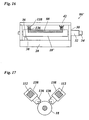
- Fig. 16 shows a preparation rack 86 'similar to the preparation rack 86 in FIG Fig. 3 is constructed, but with the difference that instead of the laser head two sensing rollers 136 are provided which roll on the peripheral surface of the printing cylinder 18 ', preferably in the vicinity of the two ends of this printing cylinder, respectively at the end of the printing pattern 88.
- Each sensing roller is resilient against the peripheral surface of the printing cylinder 18 'is biased and mounted on a high-precision displacement encoder 138, which in turn is mounted on the rail 42.
- the positions of the displacement encoders 138 on the rail 42 may be adjustable, and if necessary more than two displacement encoders may be provided with associated scanning rollers. With this embodiment, it is possible to measure at least the eccentricity and the exact diameter of the printing cylinder, in each case at the ends of the printing area, so that a possible conicity of the printing cylinder can be determined.
- the sensing roller 136 instead of the sensing roller 136 also a universally rotatably mounted Tastkugel be provided, and the associated encoder may be displaceable along the rail 42, so that it is possible to record the entire surface profile of the printing cylinder.
- the diameter of the sensing roller 136 and the Tastkugel should be chosen so that on the one hand, the rolling resistance is sufficiently small, on the other hand, however, the inertial mass is so small that the encoder can follow the surface course of the printing cylinder fast enough.
- the follower roller and the associated bearing can also be held on the rail 42 by means of a pivotable arm. In that case, the displacement sensor measures the angular displacement of this arm.
- Fig. 16 shown training analogous to the Mounter 24 after Fig. 1 applicable.
- the position of the pressure plates 26 may also be measured, at least in the circumferential direction of the printing cylinder, with the aid of the feeler rollers.
- FIG. 17 can be shown in the corresponding way also in Fig. 11 shown scanning equipment 116, 118, 120 and 122 of the printing press by corresponding combinations of touch rollers 136 and encoders 138 are replaced.
- FIG. 18 another possible embodiment of a mechanical scanning system with a follower roller 136 is illustrated.
- the printing cylinder 18 is rotatably mounted on bearing blocks 140, while the scanning system is held on separate bearing blocks 142.
- At least one of the sets of pedestals 140, 142 is controllably movable by means of a numerically controlled drive 144 along a rail 146 which is perpendicular to the axis of the impression cylinder 18.
- a parallel to the pressure cylinder 18 extending rigid guide rail 148 is mounted on which a holder 150 is arranged for the sensing roller 136 adjustable.
- the follower roller 136 is suspended by means of an arm 152 pendulum on the holder 150 so that it rests on the pressure cylinder 18 due to its own weight (and optionally an additional weight) and rolls on its peripheral surface.
- an eddy current distance sensor 154 is disposed so as to face the peripheral surface of the metal follower roller 136 and diametrically opposed to the impression cylinder 18.
- the distance sensor 154 is configured to precisely measure the width of the gap formed between this sensor and the peripheral surface of the follower roller 136. Due to the pendulum suspension of the sensing roller, the width of this gap varies according to the topography of the surface of the printing cylinder 18th
- the advantage of this arrangement is that the distance sensor directly detects the surface of the rolling on the impression cylinder 18 sensing roller 136, so that any inaccuracies in the storage of the sensing roller does not affect the accuracy.
- This allows a quick and accurate measurement of the surface profile of the impression cylinder 18 (or any other cylinder) at the axial position to which the holder 150 is set.
- a plurality of holders 150 along the guide rail 148 may be arranged so that the printing cylinder 18 can be measured in several places. The measuring positions can be selected by the staff so that the surface profile is received at the most critical points of the printing cylinder 18.
- the bearing blocks 142 are moved to a position in which the follower rollers 136 in the in FIG. 18 shown manner rests on the circumference of the printing cylinder 18 and is slightly deflected. However, a gap should remain between the feeler roller and the distance sensor 154, which corresponds at least to the expected dimensional tolerance of the pressure cylinder 18.
- the position of the peripheral surface of the printing cylinder 18, which is contacted by the follower roller 136 and which is preferably at the same height with the axis of rotation of the printing cylinder then results from the known setting position of the bearing blocks 142, the known geometry of the holder 150, the diameter the feeler roller 136 and the value measured by the distance sensor.
- a major advantage of this mechanical scanning is that the measurement result is independent of the material and the nature of the surface of the printing cylinder 18 and the pressure plates mounted thereon.
- this measuring principle can also be combined with the laser scanning described above.
- the surface of the printing cylinder can then be scanned at full width with low resolution, and at the locations where an accurate knowledge of the surface profile is desired, the holder 150 are then positioned so that the profile using the tactile rollers precise can be measured.
- FIG. 18 shows a support rod 156, on which the anilox roller can be pushed.
- the guide rail 148 should then be mounted on the bearing blocks 142 so that they can be pivoted during operation of the printing press, with built-in anilox roll out of the way.
- a rigid stylus may be provided which slides over the surface of the impression cylinder 18.
- the arm 152 and the follower roller may also be omitted, and the distance sensor 154 may be arranged to directly measure the distance to the surface of the impression cylinder.
- eddy current distance sensor 154 instead of the eddy current distance sensor 154, other contactless sensor types can be used, for example an optical sensor.
- chromatic distance sensors are known in which the surface to be scanned is irradiated with white light and the light reflected or scattered by the surface is focused by a lens. Since the refractive index of the lens is different for different colors of light, the focal length of the lens is different for different color components, so that the color measured by a color-sensitive optical element near the focal point depends on the distance of the reflective surface and thus allowing a measurement of the distance.
- the measured surface may optionally be the surface of the follower roller 136 or directly about the surface of the impression cylinder 18.
- Another conceivable measuring method is that the surface of the
- Pressure cylinder 18 is measured using a laser micrometer according to the Abschattungst.
Landscapes
- Engineering & Computer Science (AREA)
- Mechanical Engineering (AREA)
- Quality & Reliability (AREA)
- Physics & Mathematics (AREA)
- General Physics & Mathematics (AREA)
- Inking, Control Or Cleaning Of Printing Machines (AREA)
- Manufacture Or Reproduction Of Printing Formes (AREA)
- Rotary Presses (AREA)
- Advancing Webs (AREA)
Claims (3)
- Dispositif de balayage pour mesurer un profil de surface d'un cylindre en rotation (18), comportant un rouleau palpeur roulant sur le cylindre et supporté de manière mobile, caractérisé par un capteur de distance sans contact (154) agencé dans une position opposée au cylindre (18), à distance de la périphérie du rouleau palpeur, pour mesurer la position de la surface périphérique du rouleau palpeur.
- Dispositif de balayage selon la revendication 1, caractérisé en ce que le rouleau palpeur a une surface périphérique en métal et le capteur de distance (154) est un capteur à courant de Foucault.
- Bâti pour le montage de plaques d'impression (26) sur un cylindre d'impression (18) ou pour la création d'un modèle d'impression (88) sur la surface du cylindre d'impression, lequel bâti est conçu pour supporter le cylindre d'impression (18) de manière rotative, caractérisé en ce qu'il comporte un détecteur (38) pour détecter un repère de référence (36) sur le cylindre d'impression, et un dispositif de balayage (136, 138) selon la revendication 1 ou 2 pour balayer mécaniquement la surface du cylindre d'impression (18) afin de détecter la topographie de surface du cylindre d'impression.
Priority Applications (3)
| Application Number | Priority Date | Filing Date | Title |
|---|---|---|---|
| EP07818538A EP2097261B9 (fr) | 2006-10-23 | 2007-09-28 | Presse rotative et procédé pour ajuster un de ses cylindres |
| EP11150289.4A EP2298552B1 (fr) | 2006-10-23 | 2007-09-28 | Châssis de montage et procédé pour ajuster un de ses cylindres |
| PL07818538T PL2097261T3 (pl) | 2006-10-23 | 2007-09-28 | Rotacyjna maszyna drukarska oraz sposób ustawiania w niej cylindra |
Applications Claiming Priority (5)
| Application Number | Priority Date | Filing Date | Title |
|---|---|---|---|
| EP06022135.5A EP1916102B2 (fr) | 2006-10-23 | 2006-10-23 | Procédé pour ajuster un cylindre dans une machine à imprimer |
| DE200610060464 DE102006060464C5 (de) | 2006-12-19 | 2006-12-19 | Verfahren zum Einstellen einer Walze in einer Rotationsdruckmaschine |
| DE200720004717 DE202007004717U1 (de) | 2007-03-30 | 2007-03-30 | Rotationsdruckmaschine |
| EP07818538A EP2097261B9 (fr) | 2006-10-23 | 2007-09-28 | Presse rotative et procédé pour ajuster un de ses cylindres |
| PCT/EP2007/008456 WO2008049500A2 (fr) | 2006-10-23 | 2007-09-28 | Presse rotative et procédé pour ajuster un de ses cylindres |
Related Child Applications (1)
| Application Number | Title | Priority Date | Filing Date |
|---|---|---|---|
| EP11150289.4 Division-Into | 2011-01-06 |
Publications (3)
| Publication Number | Publication Date |
|---|---|
| EP2097261A2 EP2097261A2 (fr) | 2009-09-09 |
| EP2097261B1 EP2097261B1 (fr) | 2011-01-19 |
| EP2097261B9 true EP2097261B9 (fr) | 2011-03-09 |
Family
ID=38772152
Family Applications (2)
| Application Number | Title | Priority Date | Filing Date |
|---|---|---|---|
| EP11150289.4A Active EP2298552B1 (fr) | 2006-10-23 | 2007-09-28 | Châssis de montage et procédé pour ajuster un de ses cylindres |
| EP07818538A Active EP2097261B9 (fr) | 2006-10-23 | 2007-09-28 | Presse rotative et procédé pour ajuster un de ses cylindres |
Family Applications Before (1)
| Application Number | Title | Priority Date | Filing Date |
|---|---|---|---|
| EP11150289.4A Active EP2298552B1 (fr) | 2006-10-23 | 2007-09-28 | Châssis de montage et procédé pour ajuster un de ses cylindres |
Country Status (9)
| Country | Link |
|---|---|
| US (1) | US8534194B2 (fr) |
| EP (2) | EP2298552B1 (fr) |
| CN (1) | CN102381013B (fr) |
| AT (1) | ATE495892T1 (fr) |
| BR (1) | BRPI0717472A2 (fr) |
| DE (1) | DE502007006335D1 (fr) |
| ES (1) | ES2424891T3 (fr) |
| PL (1) | PL2097261T3 (fr) |
| WO (1) | WO2008049500A2 (fr) |
Families Citing this family (32)
| Publication number | Priority date | Publication date | Assignee | Title |
|---|---|---|---|---|
| BRPI0717318A2 (pt) * | 2006-10-23 | 2013-10-22 | Fischer & Krecke Gmbh | Máquina impressora rotativa e método para ajustar um cilindro da mesma |
| US20090297715A1 (en) * | 2008-05-27 | 2009-12-03 | E.I. Du Pont De Nemours And Company | Apparatus and method for treating a cylindrically-shaped element having a clamp assembly |
| DE102009046566B4 (de) * | 2009-11-10 | 2017-06-01 | Windmöller & Hölscher Kg | Körper mit einem Registermarkenfeld |
| EP2422979A1 (fr) | 2010-08-31 | 2012-02-29 | Fischer & Krecke GmbH | Presse d'impression rotative avec cylindre d'impression centrale |
| DE202013012131U1 (de) * | 2012-04-17 | 2015-06-26 | Boegli-Gravures S.A. | Prägewalzensatz für eine Vorrichtung zum Prägen von Verpackungsfolien |
| WO2014020083A2 (fr) * | 2012-07-31 | 2014-02-06 | Windmöller & Hölscher Kg | Procédé de réglage de la longueur d'impression d'une image d'impression dans une rotative polychrome |
| KR101473213B1 (ko) * | 2013-06-20 | 2014-12-22 | 주식회사 디지아이 | 디지털 프린팅장치 |
| ITBO20130568A1 (it) * | 2013-10-16 | 2015-04-17 | Bieffebi Spa | Modulo, procedimento ed apparecchiatura per l'analisi dimensionale di un cilindro porta-cliche' |
| EP3028856B2 (fr) * | 2014-12-04 | 2023-07-26 | Ball Beverage Packaging Europe Limited | Appareil d'impression |
| CN105807500B (zh) * | 2016-05-31 | 2019-03-12 | 京东方科技集团股份有限公司 | 转印装置和转印方法 |
| EP3251850A1 (fr) * | 2016-06-01 | 2017-12-06 | Windmöller & Hölscher KG | Machine d'impression flexographique comprenant un appareil monteur |
| GB2558183B (en) * | 2016-07-29 | 2020-11-25 | Crown Packaging Technology Inc | Image registration in a can decorator |
| WO2018199933A1 (fr) * | 2017-04-25 | 2018-11-01 | Hewlett-Packard Development Company, L.P. | Détermination d'une caractéristique d'un substrat |
| US11485101B2 (en) | 2017-07-14 | 2022-11-01 | Georgia-Pacific Corrugated Llc | Controls for paper, sheet, and box manufacturing systems |
| US10642551B2 (en) | 2017-07-14 | 2020-05-05 | Georgia-Pacific Corrugated Llc | Engine for generating control plans for digital pre-print paper, sheet, and box manufacturing systems |
| US20190016551A1 (en) | 2017-07-14 | 2019-01-17 | Georgia-Pacific Corrugated, LLC | Reel editor for pre-print paper, sheet, and box manufacturing systems |
| US11449290B2 (en) | 2017-07-14 | 2022-09-20 | Georgia-Pacific Corrugated Llc | Control plan for paper, sheet, and box manufacturing systems |
| US11520544B2 (en) | 2017-07-14 | 2022-12-06 | Georgia-Pacific Corrugated Llc | Waste determination for generating control plans for digital pre-print paper, sheet, and box manufacturing systems |
| DE102019111806A1 (de) * | 2019-05-07 | 2020-11-12 | Koenig & Bauer Ag | Verfahren zum Einstellen und/oder Ändern eines Farbtransfers, Druckwerk sowie Druckmaschine mit einem Druckwerk |
| DE102019111804A1 (de) * | 2019-05-07 | 2020-11-12 | Koenig & Bauer Ag | Verfahren zum Einstellen und/oder Ändern eines Farbtransfers, Druckwerk sowie Druckmaschine mit einem Druckwerk |
| CN113939403B (zh) | 2019-02-05 | 2022-07-29 | 柯尼格及包尔公开股份有限公司 | 凹版印刷装置以及在凹版印刷方法中用于设置和/或改变油墨传输的方法 |
| ES2929325T3 (es) | 2019-05-09 | 2022-11-28 | Heidelberger Druckmasch Ag | Dispositivo para medir elevaciones en la superficie de un cuerpo giratorio |
| TWI748696B (zh) * | 2019-11-18 | 2021-12-01 | 德商博斯特比勒費爾德有限公司 | 用於決定印刷機之印刷參數的方法及測試平台 |
| CN111805981A (zh) * | 2020-07-28 | 2020-10-23 | 马鞍山市富源机械制造有限公司 | 一种单双线压花轮交替压花机构及其压花工艺 |
| EP3988314A1 (fr) | 2020-10-22 | 2022-04-27 | Heidelberger Druckmaschinen AG | Dispositif de mesure d'une surface, ou de ses bossages, d'un corps rotatif et système |
| EP3988309A1 (fr) | 2020-10-22 | 2022-04-27 | Heidelberger Druckmaschinen AG | Procédé de fonctionnement d'une machine d'impression flexographique, machine d'impression flexographique, système et manchon |
| PL3988307T3 (pl) * | 2020-10-22 | 2023-09-25 | Heidelberger Druckmaschinen Ag | Sposób sterowania działaniem maszyny do druku fleksograficznego oraz maszyna do druku fleksograficznego i system obejmujący maszynę do druku fleksograficznego i urządzenie pomiarowe do pomiaru gęstości punktów formy lub tulei do druku fleksograficznego |
| EP3988305A1 (fr) * | 2020-10-22 | 2022-04-27 | Heidelberger Druckmaschinen AG | Procédé de fonctionnement d'une machine d'impression flexographique, machine d'impression flexographique, système et manchon pour une forme d'impression flexographique |
| DE102021125336A1 (de) | 2020-10-22 | 2022-04-28 | Heidelberger Druckmaschinen Aktiengesellschaft | Vorrichtung zum Vermessen von Erhebungen der Oberfläche eines Rotationskörpers und System |
| DE102021125071A1 (de) | 2020-10-22 | 2022-04-28 | Heidelberger Druckmaschinen Aktiengesellschaft | Vorrichtung zum Vermessen von Erhebungen der Oberfläche eines Rotationskörpers |
| DE102021125087A1 (de) | 2020-10-22 | 2022-04-28 | Heidelberger Druckmaschinen Aktiengesellschaft | Verfahren zum Betreiben einer Flexodruckmaschine, Flexodruckmaschine, System, Flexodruckform und Hülse für eine Flexodruckform |
| DE102021107098A1 (de) | 2021-03-23 | 2022-09-29 | ULMEX Industrie System GmbH & Co. KG | Verfahren und Maschine zur Prüfung einer Rasterwalze einer Druckvorrichtung |
Family Cites Families (47)
| Publication number | Priority date | Publication date | Assignee | Title |
|---|---|---|---|---|
| US2859532A (en) * | 1954-11-19 | 1958-11-11 | Robert E Fogg | Method and apparatus for lineup and register of printing plates |
| US3185088A (en) * | 1961-12-01 | 1965-05-25 | Harris Intertype Corp | Method and apparatus for predetermining settings for ink fountain keys |
| GB1210181A (en) * | 1968-04-10 | 1970-10-28 | Rank Organisation Ltd | Improvements in or relating to electrical filter devices |
| BE757893A (fr) * | 1970-10-22 | 1971-04-22 | Centre Rech Metallurgique | Procede et dispositif de mesure du bombe d'un cylindre, |
| DE2343855C3 (de) * | 1973-08-30 | 1975-12-04 | Windmoeller & Hoelscher, 4540 Lengerich | Einrichtung zum Vorjustieren der Formzylinder von Mehrfarbenrollenrotationsdruckmaschinen |
| DE3136703C1 (de) * | 1981-09-16 | 1982-11-04 | M.A.N.- Roland Druckmaschinen AG, 6050 Offenbach | Einrichtungen an Druckmaschinen mit Registerverstelleinrichtungen |
| DE3136704A1 (de) * | 1981-09-16 | 1983-03-31 | M.A.N.- Roland Druckmaschinen AG, 6050 Offenbach | Vorrichtung zum justieren von auf plattenzylindern montierten druckplatten |
| JPS58105007A (ja) * | 1981-12-17 | 1983-06-22 | Toshiba Corp | 画像面積測定装置 |
| DE3220800C2 (de) * | 1982-06-03 | 1986-10-30 | M.A.N.- Roland Druckmaschinen AG, 6050 Offenbach | Vorrichtung zur Abtastung von Druckplatten |
| DE3302798A1 (de) * | 1983-01-28 | 1984-08-02 | M.A.N.- Roland Druckmaschinen AG, 6050 Offenbach | Vorrichtung zum voreinstellen an druckmaschinen |
| JPS6072731A (ja) * | 1983-09-30 | 1985-04-24 | Dainippon Printing Co Ltd | 色間見当プリセツト装置 |
| US4672893A (en) * | 1985-03-21 | 1987-06-16 | Paramount Packaging | Flexo-gravure printing |
| GB8603060D0 (en) * | 1986-02-07 | 1986-03-12 | Rank Taylor Hobson Ltd | Usefulness of in situ roundness measurement |
| US4821425A (en) * | 1987-11-18 | 1989-04-18 | United States Of America As Represented By The Administrator, National Aeronautics And Space Administration | Cylindrical surface profile and diameter measuring tool and method |
| DE3912811A1 (de) * | 1989-04-19 | 1990-10-25 | Heidelberger Druckmasch Ag | Verfahren und vorrichtung fuer die feuchtmittelfuehrung einer offset-druckmaschine |
| JPH04148819A (ja) | 1990-10-12 | 1992-05-21 | Sumitomo Metal Ind Ltd | ロールプロフィール測定方法およびその装置 |
| DE4100615A1 (de) * | 1991-01-11 | 1992-07-23 | Voith Gmbh J M | Einrichtung zur messung des durchmessers von zylindern, insbesondere von walzen |
| US5117081A (en) * | 1991-04-01 | 1992-05-26 | Armco Inc. | Roll roundness measuring and machining apparatus and method |
| NL9101176A (nl) * | 1991-07-05 | 1993-02-01 | Stork Brabant Bv | Zeefdrukinrichting met continue rapportering van roterende sjablonen. |
| DE4413341C2 (de) * | 1994-04-18 | 1999-08-26 | Continental Ag | Meßeinrichtung mit einem Magnetfeldsensor zum berührungslosen Erfassen des lichten Abstandes zwischen zwei Bauteilen und deren Verwendung |
| GB9509294D0 (en) * | 1995-05-06 | 1995-06-28 | Western Atlas Uk Ltd | Improvements relating to guaging the diameter of cylindrical workpiece sections |
| DE19527199C2 (de) * | 1995-07-26 | 2002-10-31 | Baumueller Nuernberg Gmbh | Flexodruckmaschine und deren Verwendung |
| US5676058A (en) * | 1996-06-06 | 1997-10-14 | Ireton; Robert E. | Printing plate mounting system and method employing the same |
| US5771811A (en) * | 1996-10-10 | 1998-06-30 | Hurletron, Incorporated | Pre-registration system for a printing press |
| WO1998055301A1 (fr) * | 1997-06-02 | 1998-12-10 | Heidelberger Druckmaschinen Ag | Procede de gravure de cylindres d'impression |
| US6089083A (en) * | 1997-08-22 | 2000-07-18 | Curtis; John Michael | Tire inspection and preparation device |
| DE19755487B4 (de) * | 1997-12-13 | 2009-10-15 | Dr. Johannes Heidenhain Gmbh | Verfahren zur Herstellung einer Teilungsstruktur |
| DE19919741A1 (de) * | 1999-04-30 | 2000-11-02 | Heidelberger Druckmasch Ag | Verfahren zur Registersteuerung beim Übereinanderdruck mehrerer Teilfarben |
| DE19949951C2 (de) | 1999-10-16 | 2003-06-18 | Ltg Mailaender Gmbh | Lackier- oder Druckmaschine und Regelverfahren dafür |
| ITBO20000012A1 (it) * | 2000-01-18 | 2001-07-18 | Marposs Spa | Apparecchiatura per il controllo del diametro di perni . |
| IT1319446B1 (it) * | 2000-11-16 | 2003-10-10 | Corghi Spa | Dispositivo per il rilevamento dei difetti geometrici della ruota diun veicolo |
| DE10145957B4 (de) | 2001-03-27 | 2014-09-25 | Windmöller & Hölscher Kg | Vorrichtung und Verfahren zur Einstellung des Druckbildes in einer Flexodruckmaschine |
| DE10317187B4 (de) * | 2002-05-31 | 2017-05-24 | Heidelberger Druckmaschinen Ag | Automatische Übermittlung von Daten von Druckvorstufe an Druckmaschine |
| US6954991B2 (en) * | 2002-09-12 | 2005-10-18 | Showa Denko K.K. | Method and apparatus for measuring shape of tubular body |
| CN1201930C (zh) * | 2002-11-29 | 2005-05-18 | 杜建刚 | 定位印刷装置及定位印刷法 |
| CA2448879A1 (fr) * | 2002-12-09 | 2004-06-09 | Heidelberger Druckmaschinen Aktiengesellschaft | Methode et systeme d'imagerie numerique de formes d'impression |
| CA2449619A1 (fr) * | 2003-01-07 | 2004-07-07 | Heidelberger Druckmaschinen Aktiengesellschaft | Dispositif de production d'une forme d'impression |
| JP4163545B2 (ja) * | 2003-04-11 | 2008-10-08 | 株式会社ミツトヨ | 真円度測定機用基準治具 |
| TWI252809B (en) * | 2004-05-05 | 2006-04-11 | Bobst Sa | Method and device for initial adjustment of the register of the engraved cylinders of a rotary multicolour press |
| DE202004010442U1 (de) | 2004-07-03 | 2005-11-10 | Aradex Ag | Vorrichtung zur Bearbeitung eines bahnförmigen Materials |
| JP2006256176A (ja) * | 2005-03-18 | 2006-09-28 | Dainippon Printing Co Ltd | 版位相合せ装置および方法 |
| JP2006256175A (ja) * | 2005-03-18 | 2006-09-28 | Dainippon Printing Co Ltd | 版位相合せ装置および方法 |
| DE102005013360B4 (de) * | 2005-03-23 | 2018-09-13 | Manroland Web Systems Gmbh | Verfahren zum Positionieren von Druckplatten auf Zylindern einer Druckmaschine |
| CN2825284Y (zh) * | 2005-09-20 | 2006-10-11 | 浙江工业大学 | 卷尺刻度标记印刷设备 |
| US7500432B2 (en) * | 2005-10-28 | 2009-03-10 | Van Denend Mark E | Apparatus and method for balancing a printing roller having an image producing area on its outer surface |
| BRPI0717318A2 (pt) * | 2006-10-23 | 2013-10-22 | Fischer & Krecke Gmbh | Máquina impressora rotativa e método para ajustar um cilindro da mesma |
| DE602006012688D1 (de) * | 2006-10-23 | 2010-04-15 | Fischer & Krecke Gmbh | Verfahren, Monatagevorrichtung und Steuereinheit zur Justierung einer Walze in einer Druckmaschine |
-
2007
- 2007-09-28 PL PL07818538T patent/PL2097261T3/pl unknown
- 2007-09-28 AT AT07818538T patent/ATE495892T1/de active
- 2007-09-28 BR BRPI0717472-1A patent/BRPI0717472A2/pt not_active IP Right Cessation
- 2007-09-28 EP EP11150289.4A patent/EP2298552B1/fr active Active
- 2007-09-28 DE DE502007006335T patent/DE502007006335D1/de active Active
- 2007-09-28 ES ES11150289T patent/ES2424891T3/es active Active
- 2007-09-28 WO PCT/EP2007/008456 patent/WO2008049500A2/fr active Application Filing
- 2007-09-28 US US12/446,738 patent/US8534194B2/en active Active
- 2007-09-28 CN CN201110225227.2A patent/CN102381013B/zh active Active
- 2007-09-28 EP EP07818538A patent/EP2097261B9/fr active Active
Also Published As
| Publication number | Publication date |
|---|---|
| US8534194B2 (en) | 2013-09-17 |
| ATE495892T1 (de) | 2011-02-15 |
| PL2097261T3 (pl) | 2011-06-30 |
| WO2008049500A2 (fr) | 2008-05-02 |
| ES2424891T3 (es) | 2013-10-09 |
| EP2097261B1 (fr) | 2011-01-19 |
| CN102381013B (zh) | 2015-11-25 |
| EP2298552A1 (fr) | 2011-03-23 |
| US20100018419A1 (en) | 2010-01-28 |
| CN102381013A (zh) | 2012-03-21 |
| BRPI0717472A2 (pt) | 2014-03-11 |
| DE502007006335D1 (de) | 2011-03-03 |
| EP2097261A2 (fr) | 2009-09-09 |
| EP2298552B1 (fr) | 2013-07-03 |
| WO2008049500A3 (fr) | 2008-09-18 |
Similar Documents
| Publication | Publication Date | Title |
|---|---|---|
| EP2097261B9 (fr) | Presse rotative et procédé pour ajuster un de ses cylindres | |
| DE102006060464C5 (de) | Verfahren zum Einstellen einer Walze in einer Rotationsdruckmaschine | |
| WO2008049501A2 (fr) | Presse rotative et procédé pour ajuster un de ses cylindres | |
| DE202007004717U1 (de) | Rotationsdruckmaschine | |
| US20160318297A1 (en) | Method of adjusting a roller in a rotary printing press | |
| EP2498991B1 (fr) | Mesurer le rigistre dans machines d'impression | |
| EP4000931B1 (fr) | Dispositif de mesure des bosses de la surface d'un corps rotatif | |
| EP2440408B1 (fr) | Dispositif et procédé de réglage mutuel d'au moins deux cylindres d'une machine à imprimer | |
| EP2832546A1 (fr) | Imprimante dotée d'une commande de tête d'impression | |
| EP2039529A2 (fr) | Dispositif et procédé destinés à la production de plaques d'impression hélio multi-usage | |
| EP2095949A1 (fr) | Dispositif et procédé d'impression d'objets | |
| EP3988306A1 (fr) | Dispositif de mesure des élévations de la surface d'un corps rotatif | |
| DE102006060465B4 (de) | Rotationsdruckmaschine und Verfahren zum Einstellen einer Walze derselben | |
| DE202007004713U1 (de) | Rotationsdruckmaschine | |
| EP2746054B1 (fr) | Dispositif et procédé destinés à l'impression de récipients | |
| DE4221482C2 (de) | Verfahren zur Lagekontrolle eines Druckbildes auf einer Druckform | |
| EP3988314A1 (fr) | Dispositif de mesure d'une surface, ou de ses bossages, d'un corps rotatif et système | |
| EP3988313A1 (fr) | Dispositif de mesure du bossage de la surface d'un corps rotatif et système | |
| EP2688747B1 (fr) | Dispositif d'application d'au moins un milieu sur au moins un substrat et procédé de détermination reproductible d'une position d'angle de rotation d'au moins un premier cylindre d'un dispositif | |
| EP3988309A1 (fr) | Procédé de fonctionnement d'une machine d'impression flexographique, machine d'impression flexographique, système et manchon | |
| DE10003288A1 (de) | Verfahren zur Gravur von Druckzylindern | |
| DE102015017071B4 (de) | Verfahren zum Anpassen eines Druckbildes und/oder mindestens eines Zylinderaufzugs an eine Bedruckstoffänderung in einer Druckmaschine | |
| DE102015017062B4 (de) | Verfahren zum Anpassen eines Druckbildes und/oder mindestens eines Zylinderaufzugs an eine Bedruckstoffänderung in einer Druckmaschine |
Legal Events
| Date | Code | Title | Description |
|---|---|---|---|
| PUAI | Public reference made under article 153(3) epc to a published international application that has entered the european phase |
Free format text: ORIGINAL CODE: 0009012 |
|
| 17P | Request for examination filed |
Effective date: 20090420 |
|
| AK | Designated contracting states |
Kind code of ref document: A2 Designated state(s): AT BE BG CH CY CZ DE DK EE ES FI FR GB GR HU IE IS IT LI LT LU LV MC MT NL PL PT RO SE SI SK TR |
|
| DAX | Request for extension of the european patent (deleted) | ||
| 17Q | First examination report despatched |
Effective date: 20100129 |
|
| GRAP | Despatch of communication of intention to grant a patent |
Free format text: ORIGINAL CODE: EPIDOSNIGR1 |
|
| GRAS | Grant fee paid |
Free format text: ORIGINAL CODE: EPIDOSNIGR3 |
|
| GRAA | (expected) grant |
Free format text: ORIGINAL CODE: 0009210 |
|
| AK | Designated contracting states |
Kind code of ref document: B1 Designated state(s): AT BE BG CH CY CZ DE DK EE ES FI FR GB GR HU IE IS IT LI LT LU LV MC MT NL PL PT RO SE SI SK TR |
|
| REG | Reference to a national code |
Ref country code: GB Ref legal event code: FG4D Free format text: NOT ENGLISH |
|
| REG | Reference to a national code |
Ref country code: CH Ref legal event code: EP |
|
| REG | Reference to a national code |
Ref country code: IE Ref legal event code: FG4D Free format text: LANGUAGE OF EP DOCUMENT: GERMAN |
|
| REF | Corresponds to: |
Ref document number: 502007006335 Country of ref document: DE Date of ref document: 20110303 Kind code of ref document: P |
|
| REG | Reference to a national code |
Ref country code: DE Ref legal event code: R096 Ref document number: 502007006335 Country of ref document: DE Effective date: 20110303 |
|
| REG | Reference to a national code |
Ref country code: ES Ref legal event code: FG2A Ref document number: 2357864 Country of ref document: ES Kind code of ref document: T3 Effective date: 20110503 |
|
| REG | Reference to a national code |
Ref country code: NL Ref legal event code: VDEP Effective date: 20110119 |
|
| LTIE | Lt: invalidation of european patent or patent extension |
Effective date: 20110119 |
|
| REG | Reference to a national code |
Ref country code: PL Ref legal event code: T3 |
|
| PG25 | Lapsed in a contracting state [announced via postgrant information from national office to epo] |
Ref country code: IS Free format text: LAPSE BECAUSE OF FAILURE TO SUBMIT A TRANSLATION OF THE DESCRIPTION OR TO PAY THE FEE WITHIN THE PRESCRIBED TIME-LIMIT Effective date: 20110519 Ref country code: LV Free format text: LAPSE BECAUSE OF FAILURE TO SUBMIT A TRANSLATION OF THE DESCRIPTION OR TO PAY THE FEE WITHIN THE PRESCRIBED TIME-LIMIT Effective date: 20110119 Ref country code: GR Free format text: LAPSE BECAUSE OF FAILURE TO SUBMIT A TRANSLATION OF THE DESCRIPTION OR TO PAY THE FEE WITHIN THE PRESCRIBED TIME-LIMIT Effective date: 20110420 Ref country code: PT Free format text: LAPSE BECAUSE OF FAILURE TO SUBMIT A TRANSLATION OF THE DESCRIPTION OR TO PAY THE FEE WITHIN THE PRESCRIBED TIME-LIMIT Effective date: 20110519 Ref country code: LT Free format text: LAPSE BECAUSE OF FAILURE TO SUBMIT A TRANSLATION OF THE DESCRIPTION OR TO PAY THE FEE WITHIN THE PRESCRIBED TIME-LIMIT Effective date: 20110119 Ref country code: SE Free format text: LAPSE BECAUSE OF FAILURE TO SUBMIT A TRANSLATION OF THE DESCRIPTION OR TO PAY THE FEE WITHIN THE PRESCRIBED TIME-LIMIT Effective date: 20110119 |
|
| REG | Reference to a national code |
Ref country code: IE Ref legal event code: FD4D |
|
| PG25 | Lapsed in a contracting state [announced via postgrant information from national office to epo] |
Ref country code: BG Free format text: LAPSE BECAUSE OF FAILURE TO SUBMIT A TRANSLATION OF THE DESCRIPTION OR TO PAY THE FEE WITHIN THE PRESCRIBED TIME-LIMIT Effective date: 20110419 Ref country code: FI Free format text: LAPSE BECAUSE OF FAILURE TO SUBMIT A TRANSLATION OF THE DESCRIPTION OR TO PAY THE FEE WITHIN THE PRESCRIBED TIME-LIMIT Effective date: 20110119 Ref country code: NL Free format text: LAPSE BECAUSE OF FAILURE TO SUBMIT A TRANSLATION OF THE DESCRIPTION OR TO PAY THE FEE WITHIN THE PRESCRIBED TIME-LIMIT Effective date: 20110119 Ref country code: CY Free format text: LAPSE BECAUSE OF FAILURE TO SUBMIT A TRANSLATION OF THE DESCRIPTION OR TO PAY THE FEE WITHIN THE PRESCRIBED TIME-LIMIT Effective date: 20110119 Ref country code: SI Free format text: LAPSE BECAUSE OF FAILURE TO SUBMIT A TRANSLATION OF THE DESCRIPTION OR TO PAY THE FEE WITHIN THE PRESCRIBED TIME-LIMIT Effective date: 20110119 |
|
| PG25 | Lapsed in a contracting state [announced via postgrant information from national office to epo] |
Ref country code: EE Free format text: LAPSE BECAUSE OF FAILURE TO SUBMIT A TRANSLATION OF THE DESCRIPTION OR TO PAY THE FEE WITHIN THE PRESCRIBED TIME-LIMIT Effective date: 20110119 Ref country code: DK Free format text: LAPSE BECAUSE OF FAILURE TO SUBMIT A TRANSLATION OF THE DESCRIPTION OR TO PAY THE FEE WITHIN THE PRESCRIBED TIME-LIMIT Effective date: 20110119 Ref country code: IE Free format text: LAPSE BECAUSE OF FAILURE TO SUBMIT A TRANSLATION OF THE DESCRIPTION OR TO PAY THE FEE WITHIN THE PRESCRIBED TIME-LIMIT Effective date: 20110119 |
|
| PLBE | No opposition filed within time limit |
Free format text: ORIGINAL CODE: 0009261 |
|
| STAA | Information on the status of an ep patent application or granted ep patent |
Free format text: STATUS: NO OPPOSITION FILED WITHIN TIME LIMIT |
|
| PG25 | Lapsed in a contracting state [announced via postgrant information from national office to epo] |
Ref country code: RO Free format text: LAPSE BECAUSE OF FAILURE TO SUBMIT A TRANSLATION OF THE DESCRIPTION OR TO PAY THE FEE WITHIN THE PRESCRIBED TIME-LIMIT Effective date: 20110119 Ref country code: CZ Free format text: LAPSE BECAUSE OF FAILURE TO SUBMIT A TRANSLATION OF THE DESCRIPTION OR TO PAY THE FEE WITHIN THE PRESCRIBED TIME-LIMIT Effective date: 20110119 Ref country code: SK Free format text: LAPSE BECAUSE OF FAILURE TO SUBMIT A TRANSLATION OF THE DESCRIPTION OR TO PAY THE FEE WITHIN THE PRESCRIBED TIME-LIMIT Effective date: 20110119 |
|
| 26N | No opposition filed |
Effective date: 20111020 |
|
| REG | Reference to a national code |
Ref country code: DE Ref legal event code: R097 Ref document number: 502007006335 Country of ref document: DE Effective date: 20111020 |
|
| BERE | Be: lapsed |
Owner name: FISCHER & KRECKE G.M.B.H. Effective date: 20110930 |
|
| PG25 | Lapsed in a contracting state [announced via postgrant information from national office to epo] |
Ref country code: MC Free format text: LAPSE BECAUSE OF NON-PAYMENT OF DUE FEES Effective date: 20110930 |
|
| REG | Reference to a national code |
Ref country code: CH Ref legal event code: PL |
|
| REG | Reference to a national code |
Ref country code: DE Ref legal event code: R082 Ref document number: 502007006335 Country of ref document: DE Representative=s name: TER MEER STEINMEISTER & PARTNER GBR PATENTANWA, DE |
|
| PG25 | Lapsed in a contracting state [announced via postgrant information from national office to epo] |
Ref country code: BE Free format text: LAPSE BECAUSE OF NON-PAYMENT OF DUE FEES Effective date: 20110930 |
|
| PG25 | Lapsed in a contracting state [announced via postgrant information from national office to epo] |
Ref country code: CH Free format text: LAPSE BECAUSE OF NON-PAYMENT OF DUE FEES Effective date: 20110930 Ref country code: LI Free format text: LAPSE BECAUSE OF NON-PAYMENT OF DUE FEES Effective date: 20110930 |
|
| REG | Reference to a national code |
Ref country code: DE Ref legal event code: R081 Ref document number: 502007006335 Country of ref document: DE Owner name: BOBST BIELEFELD GMBH, DE Free format text: FORMER OWNER: FISCHER & KRECKE GMBH, 33609 BIELEFELD, DE Effective date: 20120615 Ref legal event code: R082 Ref document number: 502007006335 Ref country code: DE Country of ref document: DE Representative=s name: TER MEER STEINMEISTER & PARTNER PATENTANWAELTE, DE Effective date: 20120615 |
|
| REG | Reference to a national code |
Ref country code: ES Ref legal event code: PC2A Owner name: BOBST BIELEFELD GMBH Effective date: 20120807 |
|
| PG25 | Lapsed in a contracting state [announced via postgrant information from national office to epo] |
Ref country code: MT Free format text: LAPSE BECAUSE OF FAILURE TO SUBMIT A TRANSLATION OF THE DESCRIPTION OR TO PAY THE FEE WITHIN THE PRESCRIBED TIME-LIMIT Effective date: 20110119 |
|
| PG25 | Lapsed in a contracting state [announced via postgrant information from national office to epo] |
Ref country code: LU Free format text: LAPSE BECAUSE OF NON-PAYMENT OF DUE FEES Effective date: 20110928 |
|
| PG25 | Lapsed in a contracting state [announced via postgrant information from national office to epo] |
Ref country code: TR Free format text: LAPSE BECAUSE OF FAILURE TO SUBMIT A TRANSLATION OF THE DESCRIPTION OR TO PAY THE FEE WITHIN THE PRESCRIBED TIME-LIMIT Effective date: 20110119 |
|
| PG25 | Lapsed in a contracting state [announced via postgrant information from national office to epo] |
Ref country code: HU Free format text: LAPSE BECAUSE OF FAILURE TO SUBMIT A TRANSLATION OF THE DESCRIPTION OR TO PAY THE FEE WITHIN THE PRESCRIBED TIME-LIMIT Effective date: 20110119 |
|
| REG | Reference to a national code |
Ref country code: AT Ref legal event code: MM01 Ref document number: 495892 Country of ref document: AT Kind code of ref document: T Effective date: 20120928 |
|
| PG25 | Lapsed in a contracting state [announced via postgrant information from national office to epo] |
Ref country code: AT Free format text: LAPSE BECAUSE OF NON-PAYMENT OF DUE FEES Effective date: 20120928 |
|
| REG | Reference to a national code |
Ref country code: FR Ref legal event code: PLFP Year of fee payment: 10 |
|
| REG | Reference to a national code |
Ref country code: DE Ref legal event code: R082 Ref document number: 502007006335 Country of ref document: DE |
|
| REG | Reference to a national code |
Ref country code: FR Ref legal event code: PLFP Year of fee payment: 11 |
|
| REG | Reference to a national code |
Ref country code: FR Ref legal event code: PLFP Year of fee payment: 12 |
|
| P01 | Opt-out of the competence of the unified patent court (upc) registered |
Effective date: 20230519 |
|
| PGFP | Annual fee paid to national office [announced via postgrant information from national office to epo] |
Ref country code: PL Payment date: 20230630 Year of fee payment: 17 |
|
| PGFP | Annual fee paid to national office [announced via postgrant information from national office to epo] |
Ref country code: IT Payment date: 20230810 Year of fee payment: 17 Ref country code: GB Payment date: 20230810 Year of fee payment: 17 |
|
| PGFP | Annual fee paid to national office [announced via postgrant information from national office to epo] |
Ref country code: FR Payment date: 20230905 Year of fee payment: 17 Ref country code: DE Payment date: 20230802 Year of fee payment: 17 |
|
| PGFP | Annual fee paid to national office [announced via postgrant information from national office to epo] |
Ref country code: ES Payment date: 20231006 Year of fee payment: 17 |