EP2085672B1 - Connection mechanism between thin-wall stainless steel tube and joint - Google Patents
Connection mechanism between thin-wall stainless steel tube and joint Download PDFInfo
- Publication number
- EP2085672B1 EP2085672B1 EP07830219.7A EP07830219A EP2085672B1 EP 2085672 B1 EP2085672 B1 EP 2085672B1 EP 07830219 A EP07830219 A EP 07830219A EP 2085672 B1 EP2085672 B1 EP 2085672B1
- Authority
- EP
- European Patent Office
- Prior art keywords
- joint
- packing
- stainless steel
- steel pipe
- nut
- Prior art date
- Legal status (The legal status is an assumption and is not a legal conclusion. Google has not performed a legal analysis and makes no representation as to the accuracy of the status listed.)
- Active
Links
Images


Classifications
-
- F—MECHANICAL ENGINEERING; LIGHTING; HEATING; WEAPONS; BLASTING
- F16—ENGINEERING ELEMENTS AND UNITS; GENERAL MEASURES FOR PRODUCING AND MAINTAINING EFFECTIVE FUNCTIONING OF MACHINES OR INSTALLATIONS; THERMAL INSULATION IN GENERAL
- F16L—PIPES; JOINTS OR FITTINGS FOR PIPES; SUPPORTS FOR PIPES, CABLES OR PROTECTIVE TUBING; MEANS FOR THERMAL INSULATION IN GENERAL
- F16L19/00—Joints in which sealing surfaces are pressed together by means of a member, e.g. a swivel nut, screwed on, or into, one of the joint parts
- F16L19/02—Pipe ends provided with collars or flanges, integral with the pipe or not, pressed together by a screwed member
- F16L19/025—Pipe ends provided with collars or flanges, integral with the pipe or not, pressed together by a screwed member the pipe ends having integral collars or flanges
- F16L19/028—Pipe ends provided with collars or flanges, integral with the pipe or not, pressed together by a screwed member the pipe ends having integral collars or flanges the collars or flanges being obtained by deformation of the pipe wall
- F16L19/0286—Pipe ends provided with collars or flanges, integral with the pipe or not, pressed together by a screwed member the pipe ends having integral collars or flanges the collars or flanges being obtained by deformation of the pipe wall and being formed as a flange
-
- F—MECHANICAL ENGINEERING; LIGHTING; HEATING; WEAPONS; BLASTING
- F16—ENGINEERING ELEMENTS AND UNITS; GENERAL MEASURES FOR PRODUCING AND MAINTAINING EFFECTIVE FUNCTIONING OF MACHINES OR INSTALLATIONS; THERMAL INSULATION IN GENERAL
- F16L—PIPES; JOINTS OR FITTINGS FOR PIPES; SUPPORTS FOR PIPES, CABLES OR PROTECTIVE TUBING; MEANS FOR THERMAL INSULATION IN GENERAL
- F16L2201/00—Special arrangements for pipe couplings
- F16L2201/10—Indicators for correct coupling
Definitions
- This invention relates to a connecting mechanism for a thin stainless steel pipe and a joint which can simply and securely connect the thin stainless steel pipe and the joint in the field and can easily know a flaw of a coupling work.
- This kind of related art includes a structure disclosed in Japanese Utility Model Publication No. 2-37015 (patent document 1) which has been proposed by the applicant of the present application in advance.
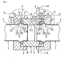
- this related art is constructed by a thin stainless steel pipe 1 in which a chevron type projection portion 5 having two inclined surfaces 5a and 5b is formed in an outer periphery of an end portion, a joint 2 in which a male thread portion 7 is formed in an outer peripheral surface of an end portion as well as having an inner diameter to which the thin stainless steel pipe 1 is inserted, a nut 4 which has a female thread portion 8 engaging with the male thread portion 7 of the joint 2 as well as having a fitting portion 11 outwardly fitted to the thin stainless steel pipe 1 so as to oppose to the joint 2 on the boundary of the chevron type projection portion 5, and a packing 3 which is provided between the joint 2 and the thin stainless steel pipe 1.
- a packing fitting portion 6 for fitting the packing 3 closely attached to one inclined surface 5b close to the end portion of the chevron type projection portion 5 to an inner periphery close to an open end portion 2a thereof.
- a pipe insertion hole 2d expanded at a thickness of the thin stainless steel pipe 1 for inserting an end portion of the thin stainless steel pipe 1 is formed in both ends of an inner hole 2c in a center portion.
- the nut 4 there is formed an inclined notch portion 10 closely attached to the other inclined surface 5a of the chevron type projection portion 5 in an inner end portion of the fitting portion 11 outwardly fitted to the thin stainless steel pipe 1, and there is formed a joint contact surface 9 with which the opening end portion 2a of the joint 2 is brought into contact at a time of screwing and firmly attaching the female thread portion 8 of the nut 4 and the male thread portion 7 of the joint 2.
- the joint contact surface 9 is formed based on an inner diameter difference between the fitting portion 11 and the female thread portion 8.
- the packing 3 is formed in such a manner as to be closely attached to each of the one inclined surface 5b of the chevron type projection portion 5 formed in the thin stainless steel pipe 1 a time of screwing and firmly attaching the female thread portion 8 of the nut 4 and the male thread portion 7 of the joint 2, the joint contact surface 9 of the nut 4, and a packing pressing surface 6a and a packing outer peripheral contact surface 6b corresponding to an inner side surface of the packing fitting portion 6 of the joint 2, and is made of an elastic material such as a rubber or the like having an approximately polygonal horizontal cross sectional shape.
- the chevron type projection portion 5 of the thin stainless steel pipe 1 is formed by using a pipe expanding apparatus K, as shown in Fig. 11 , and is formed specifically in accordance with the following procedure.
- the female thread portion 8 of the nut 4 outwardly fitted to the thin stainless steel pipe 1 is screwed and firmly attached to a male thread portion 21 formed in an outer periphery of a pipe expanding head 20 fixed to an apparatus (not shown), a shaft 25 outwardly fitting a rubber receiver 22, a pipe expanding rubber 23 and a rubber presser foot 24 is movably inserted from an end portion of the thin stainless steel pipe 1, and a leading end of the thin stainless steel pipe 1 is inserted from an opening portion of the pipe expanding head 20 until it comes into contact with a step wall 20a in an inner portion thereof.
- the rubber receiver 22 is brought into contact with the step wall 20a of the pipe expanding head 20 by pulling the shaft 25 by an apparatus (not shown) in an arrow direction, and the shaft 25 is pulled in the arrow direction, whereby the rubber presser foot 24 is pushed in the arrow direction by a locking portion 26 fixed to a leading end of the shaft 25.
- the pipe expanding rubber 23 pinched by the rubber receiver 22 and the rubber presser foot 24 is reduced its width, the pipe expanding rubber 23 is expanded at a volume reduced in a circumferential direction.
- the thin stainless steel pipe 1 is evaginated to a chevron space U in an end portion thereof in accordance with the expansion in the circumferential direction of the pipe expanding rubber 23, as shown in Fig. 12 , based on an existence of the chevron space U formed by the inclined notch portion 10 of the nut 4 and a notch portion 20b formed in an inner peripheral surface of a leading end of the pipe expanding head 20, whereby the chevron type projection portion 5 is formed.
- the nut 4 is loosened in this state so as to be detached from the pipe expanding head 20, and there is set a state in which the nut 4 is fitted to an outer periphery of the thin stainless steel 1.
- the shaft 25, and the rubber receiver 22, the pipe expanding rubber 23 and the rubber presser foot 24 which are outwardly fitted to the shaft 25 are drawn out from the thin stainless steel pipe 1.
- connection between the thin stainless steel pipe 1 and the joint 2 is achieved first of all by fitting the packing 3 from the end portion of the thin stainless steel pipe 1 so as to closely attach the fitted packing 3 to the one inclined surface 5a, or fitting the packing 3 into the packing fitting portion 6 of the joint 2 and thereafter inserting the end portion of the thin stainless steel pipe 1 to the inner portion of the pipe insertion hole 2d existing in both sides of the joint 2, as shown in a right half of Fig. 10 .
- the male thread portion 7 formed in the outer periphery of the end portion of the joint 2 is connected to the female thread portion 8 of the nut 4 outwardly fitted to the thin stainless steel pipe 1 by turning the nut sufficiently in advance until the joint contact surface 9 comes into contact with the opening end portion 2a of the joint 2 in a fastening manner. Accordingly, as shown in a left half of Fig.
- the chevron type projection portion 5 of the thin stainless steel pipe 1 is pinched by the corner portion 2b of the joint 2, the inclined notch portion 10 of the nut 4 and the packing 3 so as to be fixed, and the packing 3 is closely attached to the inclined surface 5b of the chevron type projection portion 5, the packing pressing surface 6a and the packing outer peripheral contact surface 6b corresponding to the inner side surface of the packing fitting portion 6, and the joint contact surface 9, thereby preventing the leakage of water leaking out from the gap of the connection portion between the thin stainless steel pipe 1 and the joint 2.
- This invention is made for solving the problem mentioned above, and an object of this invention is to provide a connecting mechanism for a thin stainless steel pipe and a joint which can check out a fastening failure and an insufficient fastening at a time of a piping execution for screwing and firmly attaching a male thread portion of a joint to a female thread portion of a nut fitted to a thin stainless steel pipe, based on a leakage of a pressure water.
- a connecting mechanism for a thin stainless steel pipe and a joint including: a thin stainless steel pipe in which a chevron type projection portion is formed in an outer periphery of an end portion; a joint having an inner diameter inserting the thin stainless steel pipe and forming a male thread portion in an outer peripheral surface of an end portion; a nut having a fitting portion outwardly fitted to the thin stainless steel pipe so as to oppose to the joint on the boundary of the chevron type projection portion and having a female thread portion screwed to the male thread portion of the joint; a packing provided between the joint and the thin stainless steel pipe; and a chevron type projection portion having two inclined surfaces being formed by expanding the chevron type projection portion of the thin stainless steel pipe based on a uniform force by inflating a rubber inserted to an inner portion of the chevron type projection portion in an outer peripheral direction, a packing fitting portion fitting the packing
- a connecting mechanism for a thin stainless steel pipe and a joint including: a thin stainless steel pipe in which a chevron type projection portion is formed in an outer periphery of an end portion; a joint having an inner diameter inserting the thin stainless steel pipe and forming a male thread portion in an outer peripheral surface of an end portion; a nut having a fitting portion outwardly fitted to the thin stainless steel pipe so as to oppose to the joint on the boundary of the chevron type projection portion and having a female thread portion screwed to the male thread portion of the joint; a packing provided between the joint and the thin stainless steelpipe; and a chevron type projection portion having two inclined surfaces being formed by expanding the chevron type projection portion of the thin stainless steel pipe based on a uniform force by inflating a rubber inserted to an inner portion of the chevron type projection portion in an outer peripheral direction, a packing fitting portion fitting the packing to an inner periphery of an end portion of the joint
- the water intruding into a space generated between the packing pressing surface of the packing fitting portion and the packing passes through the release groove formed in the packing outer peripheral contact surface via the gap between the joint and the thin stainless steel pipe at a position at which the fastening of the nut is insufficient, even in a state in which the outer peripheral surface of the packing is brought into contact with the packing outer peripheral contact surface of the packing fitting portion, thereby leaking out to the external portion from the screwed portion between the nut and the joint or the joint portion between the nut and the thin stainless steel pipe.
- the gap corresponding to the height of the projection is generated between the outer peripheral surface of the packing and the packing outer peripheral contact surface constructing the inner side surface of the packing fittingportion, at a position at which the fastening of the nut is insufficient. Accordingly, the water intruding into a space generated between the packing pressing portion of the packing fitting portion projection and the packing passes through the gap corresponding to the height of the projection via the gap between the joint and the thin stainless steel pipe, thereby leaking out to the external portion from the screwed portion between the nut and the joint or the joint portion between the nut and the thin stainless steel pipe.
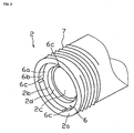
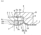
- the joint 2 forms a corner portion 2b and a packing fitting portion 6, which are brought into contact with the other inclined surface 5b of a chevron type projection portion 5 of the thin stainless steel pipe 1, in an inner periphery close to an opening end portion 2a of the joint 2, as shown in Figs. 1 to 6 .
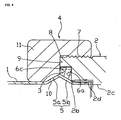
- the packing fitting portion 6 has two inner side surfaces including a packing pressing surface 6a with which a leading end surface 3a of the packing 3 is brought into contact, and a packing outer peripheral contact surface 6b with which an outer peripheral surface 3b of the packing 3 is brought into contact, as is well expressed in Figs. 5 and 6 .
- a release groove 6c is formed in an axial direction of the packing outer peripheral contact surface 6b, from the packing pressing surface 6a to the opening end portion 2a of the joint 2.
- the release groove 6c is provided for leading water existing in a gap in the packing pressing surface 6a and the leading end surface 3a of the packing 3 to a gap S3 formed by a joint contact surface 9 of the nut 4 and the opening end portion 2a of the joint 2, and a part of the packing 3 enters the release groove 6c at a time when the packing 3 is pinched between the packing pressing surface 6a and the joint contact surface 9 of the nut 4 so as to evaginate in a circumferential direction, so that the release groove 6c is sealed.
- the number of the release groove 6c is not particularly limited.
- a magnitude of a width of the release groove 6c is not particularly limited, however, if the magnitude is too small, the evaginating packing 3 is hard to enter and can not seal the groove. Accordingly, the width equal to or more than 1 mm is necessary. Further, if a depth of the groove is too deep, the evaginating packing 3 is hard to enter. Accordingly, it is preferable that the depth of the groove is equal to or less than one quarter a thickness of the packing 3. However, they are decided individually in relation to the width of the groove.
- Fig. 6 shows a case where the fastening between the female thread 8 of the nut 4 and the male thread 7 of the joint 2 is further slack.
- the water passing path of the arrow T shown in Fig. 5 is enlarged, the water widely leaks out to the external portion, and it is possible to easily check out from the external portion that the fastening is insufficient.
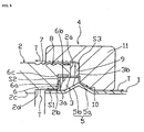
- the second embodiment is different from the first embodiment in a point that a projection 6d is formed in place of the release groove 6c in the packing outer peripheral contact surface 6b.
- a gap S is formed between the outer peripheral surface 3b of the packing 3 and the packing outer peripheral contact surface 6b by this projection 6d. If the female thread 8 of the nut 4 is sufficiently fastened to the male thread 7 of the joint 2, the packing 3 is pinched by the joint contact surface 9 of the nut 4 and the packing pressing surface 6a of the joint 2, a volume corresponding to a reduced amount evaginates in an outer peripheral direction, and the gap S is filled. Accordingly, since the water flowing within the thin stainless steel pipe 1 is closed in its passing path, no water leaks out.
- the number of the projection 6d is not particularly limited, however, the packing 3 existing in an inner portion is stably supported by three ormoreprojections. Further, it is desirable that a length of the projection 6d is formed along an entire length in an axial direction of the packing outer peripheral contact surface 6b, however, it is not always necessary to form one continuous projection, but small projections are formed on display so as to be spaced. If a protruding height of the projection 6d is too large, there is a risk that the gap can not be closed by the evagination of the packing 3. Accordingly, it is preferable that the protruding height is equal to or less than one quarter the thickness of the packing 3.
- the packing 3 is pressed into the packing fitting portion 6 of the joint 2, and the end portion of the thin stainless steel pipe 1 is thereafter inserted to the inner portion of the pipe insertion hole 2d of the joint 2. Further, it may screw the male thread 7 formed in the outer periphery of the end portion of the joint 2 and the female thread portion 8 of the nut 4 which is outwardly fitted to the thin stainless steel pipe 1 in advance until the joint contact surface 9 of the nut 4 is brought into contact with the end portion of the joint 2.
- the chevron type projection portion 5 of the thin stainless steel pipe 1 is pinched by the corner portion 2a of the joint 2, the inclined notch portion 10 of the nut 4 and the packing 3 so as to be fixed, and the packing 3 is closely attached to the other inclined surface 5b of the chevron type projection portion 5, the packing fitting portion 6b and the joint contact surface 9, thereby preventing the leakage of the fluid flowing within the thin stainless steel pipe 1. Since the case where the fastening is insufficient is the same as the first embodiment, a description thereof will be omitted.
- This invention can be effectively utilized with respect to a piping such as a water pipe or the like frequently arranged in each of floors of a building.
Landscapes
- Engineering & Computer Science (AREA)
- General Engineering & Computer Science (AREA)
- Mechanical Engineering (AREA)
- Joints With Pressure Members (AREA)
Applications Claiming Priority (1)
| Application Number | Priority Date | Filing Date | Title |
|---|---|---|---|
| PCT/JP2007/070485 WO2009050823A1 (ja) | 2007-10-19 | 2007-10-19 | 薄肉ステンレス鋼管と継手の接続機構 |
Publications (3)
| Publication Number | Publication Date |
|---|---|
| EP2085672A1 EP2085672A1 (en) | 2009-08-05 |
| EP2085672A4 EP2085672A4 (en) | 2010-12-22 |
| EP2085672B1 true EP2085672B1 (en) | 2014-05-21 |
Family
ID=40562725
Family Applications (1)
| Application Number | Title | Priority Date | Filing Date |
|---|---|---|---|
| EP07830219.7A Active EP2085672B1 (en) | 2007-10-19 | 2007-10-19 | Connection mechanism between thin-wall stainless steel tube and joint |
Country Status (7)
| Country | Link |
|---|---|
| US (1) | US7726701B2 (da) |
| EP (1) | EP2085672B1 (da) |
| JP (1) | JPWO2009050823A1 (da) |
| DK (1) | DK2085672T3 (da) |
| ES (1) | ES2488921T3 (da) |
| PT (1) | PT2085672E (da) |
| WO (1) | WO2009050823A1 (da) |
Families Citing this family (20)
| Publication number | Priority date | Publication date | Assignee | Title |
|---|---|---|---|---|
| JP5277507B2 (ja) * | 2010-06-04 | 2013-08-28 | セウング ジン インダストリー カンパニー リミテッド | ジョイントを備えたフレキシブルホース組立体 |
| JP5608463B2 (ja) * | 2010-08-02 | 2014-10-15 | 株式会社フジキン | 流体継手 |
| WO2015130427A1 (en) * | 2014-02-27 | 2015-09-03 | Sundew Technologies, Llc | Face sealed fittings |
| DE202014101748U1 (de) | 2014-04-14 | 2014-04-22 | Ti Automotive (Heidelberg) Gmbh | Schraubverbindungsvorrichtung zur Verbindung zweier Rohre |
| PT3361133T (pt) * | 2015-10-06 | 2020-07-15 | O N Ind Co Ltd | Mecanismo de conexão para tubo de cobre e junção |
| SE1551317A1 (en) * | 2015-10-13 | 2017-04-14 | Sapa As | Brake tube connector and brake tube connector assembly |
| GB2544754B (en) * | 2015-11-24 | 2018-11-07 | Self Energising Coupling Co Ltd | Improved fluid coupling |
| CN109073120B (zh) * | 2016-03-23 | 2021-02-19 | 斯瓦戈洛克公司 | 具有行程阻抗特征的导管配件 |
| JP2017115577A (ja) * | 2017-03-30 | 2017-06-29 | Jfeスチール株式会社 | 鋼管の接合継手 |
| US11519529B2 (en) * | 2017-05-31 | 2022-12-06 | Hanon Systems | Metal sealing threaded (tube-o) fitting |
| CN107035924A (zh) * | 2017-06-01 | 2017-08-11 | 曾广新 | 内置密封式连接单元、组件及管路系统 |
| CN107869616A (zh) * | 2017-11-30 | 2018-04-03 | 信宜市家加美不锈钢制品有限公司 | 一种方便牢固的不锈钢水管连接结构 |
| JP7017233B2 (ja) * | 2018-02-28 | 2022-02-08 | オーエヌ工業株式会社 | 薄肉ステンレス鋼管の拡管装置 |
| US20190360648A1 (en) * | 2018-05-22 | 2019-11-28 | Habitex Corporation | Lighting assembly |
| JP7485400B2 (ja) * | 2020-07-02 | 2024-05-16 | 株式会社サンギ | シール装置 |
| ES2948645T3 (es) * | 2020-12-23 | 2023-09-15 | Walter Stauffenberg Gmbh & Co Kg | Racor de tubo |
| JP7660402B2 (ja) * | 2021-03-16 | 2025-04-11 | 株式会社リケンCkjv | 管継手 |
| JP7230264B1 (ja) | 2022-06-29 | 2023-02-28 | オーエヌ工業株式会社 | 鋼管と継手の接続機構 |
| TWI815756B (zh) * | 2022-12-22 | 2023-09-11 | 中鴻鋼鐵股份有限公司 | 耐腐蝕複合管材 |
| JP7445339B1 (ja) | 2023-01-30 | 2024-03-07 | オーエヌ工業株式会社 | 鋼管と継手の接続機構 |
Family Cites Families (39)
| Publication number | Priority date | Publication date | Assignee | Title |
|---|---|---|---|---|
| US771682A (en) * | 1904-03-26 | 1904-10-04 | Leon Sussman | Pipe-joint. |
| US1058542A (en) * | 1912-10-01 | 1913-04-08 | Sydney L Brown | Pipe-coupling. |
| US1664125A (en) * | 1926-11-10 | 1928-03-27 | John R Lowrey | Hose coupling |
| US1782737A (en) * | 1927-01-19 | 1930-11-25 | Lee H Mahon | Casing suspension head |
| US2082164A (en) * | 1934-03-13 | 1937-06-01 | Cons Gas Electric Light And Po | Tube fitting |
| US2323099A (en) * | 1941-12-05 | 1943-06-29 | Patten Walter Evans | Tube fitting |
| US2453391A (en) * | 1946-01-14 | 1948-11-09 | New York Air Brake Co | Tubing connection |
| US2448888A (en) * | 1946-04-05 | 1948-09-07 | Chicago Forging & Mfg Co | Fitting |
| US2685461A (en) * | 1949-09-22 | 1954-08-03 | Mueller Co | Pipe coupling |
| US3258279A (en) * | 1964-11-30 | 1966-06-28 | Robert R Rcddy | Connector seal |
| US3288494A (en) * | 1965-08-11 | 1966-11-29 | Cajon Co | Union coupling |
| US3393930A (en) * | 1966-08-18 | 1968-07-23 | Parker Hannifin Corp | Coupling for thin-walled tubes |
| US3584900A (en) * | 1968-09-18 | 1971-06-15 | Sno Trik Co | High-pressure sealing and gripping device |
| US3807773A (en) * | 1971-12-02 | 1974-04-30 | H Brune | Conduit union and gasket |
| JPS56149186U (da) * | 1980-04-08 | 1981-11-09 | ||
| JPS59107390U (ja) * | 1983-01-10 | 1984-07-19 | オ−エヌ工業株式会社 | 薄肉ステンレス鋼管と継手の接続機構 |
| JPS62188687U (da) * | 1986-05-22 | 1987-12-01 | ||
| JPH01199089A (ja) * | 1988-02-02 | 1989-08-10 | Nec Corp | メタルcリング固定機構付継手 |
| WO1989011058A1 (fr) * | 1988-05-09 | 1989-11-16 | O.N. Industries Co., Ltd. | Mecanisme de liaison pour conduites en acier inoxydable a parois minces et joint |
| JP2770332B2 (ja) | 1988-07-27 | 1998-07-02 | 日産自動車株式会社 | 車両のサスペンション制御装置 |
| JPH06235484A (ja) * | 1993-02-05 | 1994-08-23 | Teikoku Kinzoku Kk | スプリンクラー巻き出し配管の継手部 |
| US5529349A (en) * | 1993-08-25 | 1996-06-25 | Itt Corporation | Mounting apparatus with reduced resistance bead seal |
| DE19526316C3 (de) * | 1995-07-19 | 2002-03-07 | Walterscheid Gmbh Jean | Rohrverbindung |
| CN1196784A (zh) * | 1995-08-16 | 1998-10-21 | 曼弗雷德·弗勒利希 | 高压连接系统 |
| DE19742917C2 (de) * | 1997-09-29 | 2002-11-14 | Walterscheid Gmbh Jean | Schraubverbindung mit Stützring |
| DE19951460C2 (de) * | 1999-10-26 | 2001-09-27 | Walterscheid Gmbh Jean | Rohrverbindung mit einem dem Rohr angeformten Verbindungsabschnitt |
| DE19958475A1 (de) * | 1999-11-30 | 2001-06-13 | Parker Hannifin Gmbh | Rohrverbindung und Verfahren zu ihrer Herstellung |
| US6527304B1 (en) * | 2000-02-17 | 2003-03-04 | Ford Global Technologies, Inc. | Brake tube connector |
| JP4463434B2 (ja) * | 2001-01-16 | 2010-05-19 | 株式会社オンダ製作所 | インコア |
| JP3682408B2 (ja) * | 2001-02-16 | 2005-08-10 | 株式会社オンダ製作所 | 継手 |
| DE10124874A1 (de) * | 2001-05-22 | 2002-11-28 | Voss Fluidtechnik Gmbh & Co Kg | Rohrverschraubung |
| CN100406797C (zh) * | 2001-12-25 | 2008-07-30 | 未来工业株式会社 | 水管的端部结构及制造方法、水管 |
| FR2856132B1 (fr) * | 2003-06-10 | 2005-07-22 | Comap | Dispositif d'emboiture de raccord a sertir a gorge de profondeur variable |
| US6877781B2 (en) * | 2003-07-31 | 2005-04-12 | Highlands Corporation | Corrugated tube fitting |
| JP2005090531A (ja) * | 2003-09-12 | 2005-04-07 | Mym Corp | 管継手 |
| US6988748B2 (en) * | 2003-12-23 | 2006-01-24 | Martinrea Industries, Inc. | Fluid coupling assembly |
| DE102004059909A1 (de) * | 2004-12-13 | 2006-06-14 | Robert Bosch Gmbh | Rohrleitungsverschraubung sowie Überwurfmutter, Anschlussstutzen und Rohrleitung für eine Rohrleitungsverschraubung |
| US20070024054A1 (en) * | 2005-07-27 | 2007-02-01 | Chung Cheng Faucet Co., Ltd. | Tube connection structure |
| JP2007100847A (ja) * | 2005-10-04 | 2007-04-19 | On Industries Ltd | パッキン及び継手と鋼管の接続機構 |
-
2007
- 2007-10-19 DK DK07830219.7T patent/DK2085672T3/da active
- 2007-10-19 WO PCT/JP2007/070485 patent/WO2009050823A1/ja not_active Ceased
- 2007-10-19 PT PT78302197T patent/PT2085672E/pt unknown
- 2007-10-19 JP JP2009537838A patent/JPWO2009050823A1/ja active Pending
- 2007-10-19 ES ES07830219.7T patent/ES2488921T3/es active Active
- 2007-10-19 EP EP07830219.7A patent/EP2085672B1/en active Active
-
2008
- 2008-09-18 US US12/212,747 patent/US7726701B2/en active Active
Also Published As
| Publication number | Publication date |
|---|---|
| US20090102190A1 (en) | 2009-04-23 |
| WO2009050823A1 (ja) | 2009-04-23 |
| DK2085672T3 (da) | 2014-09-01 |
| EP2085672A4 (en) | 2010-12-22 |
| JPWO2009050823A1 (ja) | 2011-02-24 |
| EP2085672A1 (en) | 2009-08-05 |
| PT2085672E (pt) | 2014-07-18 |
| US7726701B2 (en) | 2010-06-01 |
| ES2488921T3 (es) | 2014-09-01 |
Similar Documents
| Publication | Publication Date | Title |
|---|---|---|
| EP2085672B1 (en) | Connection mechanism between thin-wall stainless steel tube and joint | |
| US8585100B2 (en) | Press-connect fitting with improved grab ring function | |
| KR20130052967A (ko) | 파이프 연결구 | |
| EP3770475B1 (en) | Pipe joint and method for joining pipes | |
| JP2010096305A (ja) | 管継手構造 | |
| KR101538337B1 (ko) | 배관연결구 및 배관의 결합체 | |
| KR200437907Y1 (ko) | 에어콘용 배관 연결장치 | |
| JP2016142293A (ja) | 薄肉ステンレス鋼管と継手の接続機構 | |
| KR101104085B1 (ko) | 파이프 연결구 | |
| US5199750A (en) | Snake tail ring socket | |
| KR20150004585A (ko) | 파이프 고정이 용이한 배관 커플러 | |
| JP4671645B2 (ja) | 離脱防止管継手 | |
| KR100953158B1 (ko) | 분기관 연결구 | |
| JP2014185674A (ja) | 薄肉ステンレス鋼管と継手の接続機構 | |
| JP6764668B2 (ja) | 管継手および管の接合方法 | |
| JP4827171B2 (ja) | 管用栓を用いた管端閉塞工法 | |
| KR101351201B1 (ko) | 파이프 결속장치 및 방법 | |
| KR20070079965A (ko) | 삽입식 이중수밀 이음관 | |
| JP4597889B2 (ja) | 管継手 | |
| JP2009063546A (ja) | ガスメータ取付ユニット | |
| KR101673243B1 (ko) | 힌지를 이용한 스테인리스 파이프를 체결하는 체결구 및 이를 이용한 스테인리스 파이프 체결 어셈블리 | |
| JP2006322542A (ja) | 管継手 | |
| KR101209622B1 (ko) | 패킹 및 이음매와 강관의 접속기구 | |
| KR101783524B1 (ko) | 연결관의 파이프 체결구조 | |
| KR101418334B1 (ko) | 파이프 결속장치 및 방법 |
Legal Events
| Date | Code | Title | Description |
|---|---|---|---|
| PUAI | Public reference made under article 153(3) epc to a published international application that has entered the european phase |
Free format text: ORIGINAL CODE: 0009012 |
|
| 17P | Request for examination filed |
Effective date: 20081108 |
|
| AK | Designated contracting states |
Kind code of ref document: A1 Designated state(s): AT BE BG CH CY CZ DE DK EE ES FI FR GB GR HU IE IS IT LI LT LU LV MC MT NL PL PT RO SE SI SK TR |
|
| AX | Request for extension of the european patent |
Extension state: AL BA HR MK RS |
|
| RBV | Designated contracting states (corrected) |
Designated state(s): AT BE BG CH CY CZ DE DK EE ES FI FR GB GR HU IE IS IT LI LT LU LV MC MT NL PL PT RO SE SI SK TR |
|
| A4 | Supplementary search report drawn up and despatched |
Effective date: 20101122 |
|
| DAX | Request for extension of the european patent (deleted) | ||
| 17Q | First examination report despatched |
Effective date: 20120413 |
|
| REG | Reference to a national code |
Ref country code: DE Ref legal event code: R079 Ref document number: 602007036885 Country of ref document: DE Free format text: PREVIOUS MAIN CLASS: F16L0019000000 Ipc: F16L0019028000 |
|
| RIC1 | Information provided on ipc code assigned before grant |
Ipc: F16L 19/028 20060101AFI20131203BHEP |
|
| GRAP | Despatch of communication of intention to grant a patent |
Free format text: ORIGINAL CODE: EPIDOSNIGR1 |
|
| INTG | Intention to grant announced |
Effective date: 20140217 |
|
| GRAS | Grant fee paid |
Free format text: ORIGINAL CODE: EPIDOSNIGR3 |
|
| GRAA | (expected) grant |
Free format text: ORIGINAL CODE: 0009210 |
|
| AK | Designated contracting states |
Kind code of ref document: B1 Designated state(s): AT BE BG CH CY CZ DE DK EE ES FI FR GB GR HU IE IS IT LI LT LU LV MC MT NL PL PT RO SE SI SK TR |
|
| REG | Reference to a national code |
Ref country code: GB Ref legal event code: FG4D |
|
| REG | Reference to a national code |
Ref country code: CH Ref legal event code: EP |
|
| REG | Reference to a national code |
Ref country code: AT Ref legal event code: REF Ref document number: 669780 Country of ref document: AT Kind code of ref document: T Effective date: 20140615 |
|
| REG | Reference to a national code |
Ref country code: IE Ref legal event code: FG4D |
|
| REG | Reference to a national code |
Ref country code: DE Ref legal event code: R096 Ref document number: 602007036885 Country of ref document: DE Effective date: 20140703 |
|
| REG | Reference to a national code |
Ref country code: NL Ref legal event code: T3 |
|
| REG | Reference to a national code |
Ref country code: PT Ref legal event code: SC4A Free format text: AVAILABILITY OF NATIONAL TRANSLATION Effective date: 20140708 |
|
| REG | Reference to a national code |
Ref country code: DK Ref legal event code: T3 Effective date: 20140825 Ref country code: ES Ref legal event code: FG2A Ref document number: 2488921 Country of ref document: ES Kind code of ref document: T3 Effective date: 20140901 |
|
| REG | Reference to a national code |
Ref country code: SE Ref legal event code: TRGR |
|
| REG | Reference to a national code |
Ref country code: AT Ref legal event code: MK05 Ref document number: 669780 Country of ref document: AT Kind code of ref document: T Effective date: 20140521 |
|
| REG | Reference to a national code |
Ref country code: LT Ref legal event code: MG4D |
|
| PG25 | Lapsed in a contracting state [announced via postgrant information from national office to epo] |
Ref country code: GR Free format text: LAPSE BECAUSE OF FAILURE TO SUBMIT A TRANSLATION OF THE DESCRIPTION OR TO PAY THE FEE WITHIN THE PRESCRIBED TIME-LIMIT Effective date: 20140822 Ref country code: FI Free format text: LAPSE BECAUSE OF FAILURE TO SUBMIT A TRANSLATION OF THE DESCRIPTION OR TO PAY THE FEE WITHIN THE PRESCRIBED TIME-LIMIT Effective date: 20140521 Ref country code: IS Free format text: LAPSE BECAUSE OF FAILURE TO SUBMIT A TRANSLATION OF THE DESCRIPTION OR TO PAY THE FEE WITHIN THE PRESCRIBED TIME-LIMIT Effective date: 20140921 Ref country code: LT Free format text: LAPSE BECAUSE OF FAILURE TO SUBMIT A TRANSLATION OF THE DESCRIPTION OR TO PAY THE FEE WITHIN THE PRESCRIBED TIME-LIMIT Effective date: 20140521 |
|
| PG25 | Lapsed in a contracting state [announced via postgrant information from national office to epo] |
Ref country code: LV Free format text: LAPSE BECAUSE OF FAILURE TO SUBMIT A TRANSLATION OF THE DESCRIPTION OR TO PAY THE FEE WITHIN THE PRESCRIBED TIME-LIMIT Effective date: 20140521 Ref country code: PL Free format text: LAPSE BECAUSE OF FAILURE TO SUBMIT A TRANSLATION OF THE DESCRIPTION OR TO PAY THE FEE WITHIN THE PRESCRIBED TIME-LIMIT Effective date: 20140521 Ref country code: AT Free format text: LAPSE BECAUSE OF FAILURE TO SUBMIT A TRANSLATION OF THE DESCRIPTION OR TO PAY THE FEE WITHIN THE PRESCRIBED TIME-LIMIT Effective date: 20140521 |
|
| PG25 | Lapsed in a contracting state [announced via postgrant information from national office to epo] |
Ref country code: CZ Free format text: LAPSE BECAUSE OF FAILURE TO SUBMIT A TRANSLATION OF THE DESCRIPTION OR TO PAY THE FEE WITHIN THE PRESCRIBED TIME-LIMIT Effective date: 20140521 Ref country code: SK Free format text: LAPSE BECAUSE OF FAILURE TO SUBMIT A TRANSLATION OF THE DESCRIPTION OR TO PAY THE FEE WITHIN THE PRESCRIBED TIME-LIMIT Effective date: 20140521 Ref country code: BE Free format text: LAPSE BECAUSE OF FAILURE TO SUBMIT A TRANSLATION OF THE DESCRIPTION OR TO PAY THE FEE WITHIN THE PRESCRIBED TIME-LIMIT Effective date: 20140521 Ref country code: EE Free format text: LAPSE BECAUSE OF FAILURE TO SUBMIT A TRANSLATION OF THE DESCRIPTION OR TO PAY THE FEE WITHIN THE PRESCRIBED TIME-LIMIT Effective date: 20140521 Ref country code: RO Free format text: LAPSE BECAUSE OF FAILURE TO SUBMIT A TRANSLATION OF THE DESCRIPTION OR TO PAY THE FEE WITHIN THE PRESCRIBED TIME-LIMIT Effective date: 20140521 |
|
| REG | Reference to a national code |
Ref country code: DE Ref legal event code: R097 Ref document number: 602007036885 Country of ref document: DE |
|
| PLBE | No opposition filed within time limit |
Free format text: ORIGINAL CODE: 0009261 |
|
| STAA | Information on the status of an ep patent application or granted ep patent |
Free format text: STATUS: NO OPPOSITION FILED WITHIN TIME LIMIT |
|
| 26N | No opposition filed |
Effective date: 20150224 |
|
| PG25 | Lapsed in a contracting state [announced via postgrant information from national office to epo] |
Ref country code: LU Free format text: LAPSE BECAUSE OF FAILURE TO SUBMIT A TRANSLATION OF THE DESCRIPTION OR TO PAY THE FEE WITHIN THE PRESCRIBED TIME-LIMIT Effective date: 20141019 Ref country code: MC Free format text: LAPSE BECAUSE OF FAILURE TO SUBMIT A TRANSLATION OF THE DESCRIPTION OR TO PAY THE FEE WITHIN THE PRESCRIBED TIME-LIMIT Effective date: 20140521 |
|
| REG | Reference to a national code |
Ref country code: CH Ref legal event code: PL |
|
| REG | Reference to a national code |
Ref country code: DE Ref legal event code: R097 Ref document number: 602007036885 Country of ref document: DE Effective date: 20150224 |
|
| REG | Reference to a national code |
Ref country code: IE Ref legal event code: MM4A |
|
| PG25 | Lapsed in a contracting state [announced via postgrant information from national office to epo] |
Ref country code: SI Free format text: LAPSE BECAUSE OF FAILURE TO SUBMIT A TRANSLATION OF THE DESCRIPTION OR TO PAY THE FEE WITHIN THE PRESCRIBED TIME-LIMIT Effective date: 20140521 Ref country code: LI Free format text: LAPSE BECAUSE OF NON-PAYMENT OF DUE FEES Effective date: 20141031 Ref country code: CH Free format text: LAPSE BECAUSE OF NON-PAYMENT OF DUE FEES Effective date: 20141031 |
|
| REG | Reference to a national code |
Ref country code: FR Ref legal event code: PLFP Year of fee payment: 9 |
|
| PG25 | Lapsed in a contracting state [announced via postgrant information from national office to epo] |
Ref country code: IE Free format text: LAPSE BECAUSE OF NON-PAYMENT OF DUE FEES Effective date: 20141019 |
|
| PG25 | Lapsed in a contracting state [announced via postgrant information from national office to epo] |
Ref country code: BG Free format text: LAPSE BECAUSE OF FAILURE TO SUBMIT A TRANSLATION OF THE DESCRIPTION OR TO PAY THE FEE WITHIN THE PRESCRIBED TIME-LIMIT Effective date: 20140521 |
|
| PG25 | Lapsed in a contracting state [announced via postgrant information from national office to epo] |
Ref country code: CY Free format text: LAPSE BECAUSE OF FAILURE TO SUBMIT A TRANSLATION OF THE DESCRIPTION OR TO PAY THE FEE WITHIN THE PRESCRIBED TIME-LIMIT Effective date: 20140521 |
|
| PG25 | Lapsed in a contracting state [announced via postgrant information from national office to epo] |
Ref country code: MT Free format text: LAPSE BECAUSE OF FAILURE TO SUBMIT A TRANSLATION OF THE DESCRIPTION OR TO PAY THE FEE WITHIN THE PRESCRIBED TIME-LIMIT Effective date: 20140521 Ref country code: HU Free format text: LAPSE BECAUSE OF FAILURE TO SUBMIT A TRANSLATION OF THE DESCRIPTION OR TO PAY THE FEE WITHIN THE PRESCRIBED TIME-LIMIT; INVALID AB INITIO Effective date: 20071019 |
|
| REG | Reference to a national code |
Ref country code: FR Ref legal event code: PLFP Year of fee payment: 10 |
|
| REG | Reference to a national code |
Ref country code: FR Ref legal event code: PLFP Year of fee payment: 11 |
|
| REG | Reference to a national code |
Ref country code: FR Ref legal event code: PLFP Year of fee payment: 12 |
|
| PGFP | Annual fee paid to national office [announced via postgrant information from national office to epo] |
Ref country code: NL Payment date: 20231023 Year of fee payment: 17 |
|
| PGFP | Annual fee paid to national office [announced via postgrant information from national office to epo] |
Ref country code: GB Payment date: 20231025 Year of fee payment: 17 |
|
| PGFP | Annual fee paid to national office [announced via postgrant information from national office to epo] |
Ref country code: ES Payment date: 20231117 Year of fee payment: 17 |
|
| PGFP | Annual fee paid to national office [announced via postgrant information from national office to epo] |
Ref country code: TR Payment date: 20231012 Year of fee payment: 17 Ref country code: SE Payment date: 20231025 Year of fee payment: 17 Ref country code: PT Payment date: 20231016 Year of fee payment: 17 Ref country code: IT Payment date: 20231031 Year of fee payment: 17 Ref country code: FR Payment date: 20231023 Year of fee payment: 17 Ref country code: DK Payment date: 20231025 Year of fee payment: 17 Ref country code: DE Payment date: 20231208 Year of fee payment: 17 |
|
| REG | Reference to a national code |
Ref country code: DE Ref legal event code: R119 Ref document number: 602007036885 Country of ref document: DE |
|
| REG | Reference to a national code |
Ref country code: DK Ref legal event code: EBP Effective date: 20241031 |
|
| REG | Reference to a national code |
Ref country code: SE Ref legal event code: EUG |
|
| REG | Reference to a national code |
Ref country code: NL Ref legal event code: MM Effective date: 20241101 |
|
| GBPC | Gb: european patent ceased through non-payment of renewal fee |
Effective date: 20241019 |
|
| PG25 | Lapsed in a contracting state [announced via postgrant information from national office to epo] |
Ref country code: DE Free format text: LAPSE BECAUSE OF NON-PAYMENT OF DUE FEES Effective date: 20250501 |
|
| PG25 | Lapsed in a contracting state [announced via postgrant information from national office to epo] |
Ref country code: GB Free format text: LAPSE BECAUSE OF NON-PAYMENT OF DUE FEES Effective date: 20241019 |
|
| PG25 | Lapsed in a contracting state [announced via postgrant information from national office to epo] |
Ref country code: NL Free format text: LAPSE BECAUSE OF NON-PAYMENT OF DUE FEES Effective date: 20241101 |
|
| PG25 | Lapsed in a contracting state [announced via postgrant information from national office to epo] |
Ref country code: PT Free format text: LAPSE BECAUSE OF NON-PAYMENT OF DUE FEES Effective date: 20250421 |
|
| PG25 | Lapsed in a contracting state [announced via postgrant information from national office to epo] |
Ref country code: FR Free format text: LAPSE BECAUSE OF NON-PAYMENT OF DUE FEES Effective date: 20241031 |
|
| PG25 | Lapsed in a contracting state [announced via postgrant information from national office to epo] |
Ref country code: DK Free format text: LAPSE BECAUSE OF NON-PAYMENT OF DUE FEES Effective date: 20241031 |
|
| PG25 | Lapsed in a contracting state [announced via postgrant information from national office to epo] |
Ref country code: SE Free format text: LAPSE BECAUSE OF NON-PAYMENT OF DUE FEES Effective date: 20241020 Ref country code: IT Free format text: LAPSE BECAUSE OF NON-PAYMENT OF DUE FEES Effective date: 20241019 |
|
| REG | Reference to a national code |
Ref country code: ES Ref legal event code: FD2A Effective date: 20251201 |
|
| PG25 | Lapsed in a contracting state [announced via postgrant information from national office to epo] |
Ref country code: ES Free format text: LAPSE BECAUSE OF NON-PAYMENT OF DUE FEES Effective date: 20241020 |