EP2085672B1 - Connection mechanism between thin-wall stainless steel tube and joint - Google Patents
Connection mechanism between thin-wall stainless steel tube and joint Download PDFInfo
- Publication number
- EP2085672B1 EP2085672B1 EP07830219.7A EP07830219A EP2085672B1 EP 2085672 B1 EP2085672 B1 EP 2085672B1 EP 07830219 A EP07830219 A EP 07830219A EP 2085672 B1 EP2085672 B1 EP 2085672B1
- Authority
- EP
- European Patent Office
- Prior art keywords
- joint
- packing
- stainless steel
- steel pipe
- nut
- Prior art date
- Legal status (The legal status is an assumption and is not a legal conclusion. Google has not performed a legal analysis and makes no representation as to the accuracy of the status listed.)
- Active
Links
- 229910001220 stainless steel Inorganic materials 0.000 title claims description 82
- 239000010935 stainless steel Substances 0.000 title claims description 82
- 238000012856 packing Methods 0.000 claims description 120
- 230000002093 peripheral effect Effects 0.000 claims description 33
- XLYOFNOQVPJJNP-UHFFFAOYSA-N water Substances O XLYOFNOQVPJJNP-UHFFFAOYSA-N 0.000 description 32
- 230000008878 coupling Effects 0.000 description 5
- 238000010168 coupling process Methods 0.000 description 5
- 238000005859 coupling reaction Methods 0.000 description 5
- 238000003780 insertion Methods 0.000 description 4
- 230000037431 insertion Effects 0.000 description 4
- 238000010276 construction Methods 0.000 description 2
- 239000012530 fluid Substances 0.000 description 2
- 239000013013 elastic material Substances 0.000 description 1
- 238000000034 method Methods 0.000 description 1
- 230000002123 temporal effect Effects 0.000 description 1
Images


Classifications
-
- F—MECHANICAL ENGINEERING; LIGHTING; HEATING; WEAPONS; BLASTING
- F16—ENGINEERING ELEMENTS AND UNITS; GENERAL MEASURES FOR PRODUCING AND MAINTAINING EFFECTIVE FUNCTIONING OF MACHINES OR INSTALLATIONS; THERMAL INSULATION IN GENERAL
- F16L—PIPES; JOINTS OR FITTINGS FOR PIPES; SUPPORTS FOR PIPES, CABLES OR PROTECTIVE TUBING; MEANS FOR THERMAL INSULATION IN GENERAL
- F16L19/00—Joints in which sealing surfaces are pressed together by means of a member, e.g. a swivel nut, screwed on or into one of the joint parts
- F16L19/02—Pipe ends provided with collars or flanges, integral with the pipe or not, pressed together by a screwed member
- F16L19/025—Pipe ends provided with collars or flanges, integral with the pipe or not, pressed together by a screwed member the pipe ends having integral collars or flanges
- F16L19/028—Pipe ends provided with collars or flanges, integral with the pipe or not, pressed together by a screwed member the pipe ends having integral collars or flanges the collars or flanges being obtained by deformation of the pipe wall
- F16L19/0286—Pipe ends provided with collars or flanges, integral with the pipe or not, pressed together by a screwed member the pipe ends having integral collars or flanges the collars or flanges being obtained by deformation of the pipe wall and being formed as a flange
-
- F—MECHANICAL ENGINEERING; LIGHTING; HEATING; WEAPONS; BLASTING
- F16—ENGINEERING ELEMENTS AND UNITS; GENERAL MEASURES FOR PRODUCING AND MAINTAINING EFFECTIVE FUNCTIONING OF MACHINES OR INSTALLATIONS; THERMAL INSULATION IN GENERAL
- F16L—PIPES; JOINTS OR FITTINGS FOR PIPES; SUPPORTS FOR PIPES, CABLES OR PROTECTIVE TUBING; MEANS FOR THERMAL INSULATION IN GENERAL
- F16L2201/00—Special arrangements for pipe couplings
- F16L2201/10—Indicators for correct coupling
Definitions
- This invention relates to a connecting mechanism for a thin stainless steel pipe and a joint which can simply and securely connect the thin stainless steel pipe and the joint in the field and can easily know a flaw of a coupling work.
- This kind of related art includes a structure disclosed in Japanese Utility Model Publication No. 2-37015 (patent document 1) which has been proposed by the applicant of the present application in advance.
- this related art is constructed by a thin stainless steel pipe 1 in which a chevron type projection portion 5 having two inclined surfaces 5a and 5b is formed in an outer periphery of an end portion, a joint 2 in which a male thread portion 7 is formed in an outer peripheral surface of an end portion as well as having an inner diameter to which the thin stainless steel pipe 1 is inserted, a nut 4 which has a female thread portion 8 engaging with the male thread portion 7 of the joint 2 as well as having a fitting portion 11 outwardly fitted to the thin stainless steel pipe 1 so as to oppose to the joint 2 on the boundary of the chevron type projection portion 5, and a packing 3 which is provided between the joint 2 and the thin stainless steel pipe 1.
- a packing fitting portion 6 for fitting the packing 3 closely attached to one inclined surface 5b close to the end portion of the chevron type projection portion 5 to an inner periphery close to an open end portion 2a thereof.
- a pipe insertion hole 2d expanded at a thickness of the thin stainless steel pipe 1 for inserting an end portion of the thin stainless steel pipe 1 is formed in both ends of an inner hole 2c in a center portion.
- the nut 4 there is formed an inclined notch portion 10 closely attached to the other inclined surface 5a of the chevron type projection portion 5 in an inner end portion of the fitting portion 11 outwardly fitted to the thin stainless steel pipe 1, and there is formed a joint contact surface 9 with which the opening end portion 2a of the joint 2 is brought into contact at a time of screwing and firmly attaching the female thread portion 8 of the nut 4 and the male thread portion 7 of the joint 2.
- the joint contact surface 9 is formed based on an inner diameter difference between the fitting portion 11 and the female thread portion 8.
- the packing 3 is formed in such a manner as to be closely attached to each of the one inclined surface 5b of the chevron type projection portion 5 formed in the thin stainless steel pipe 1 a time of screwing and firmly attaching the female thread portion 8 of the nut 4 and the male thread portion 7 of the joint 2, the joint contact surface 9 of the nut 4, and a packing pressing surface 6a and a packing outer peripheral contact surface 6b corresponding to an inner side surface of the packing fitting portion 6 of the joint 2, and is made of an elastic material such as a rubber or the like having an approximately polygonal horizontal cross sectional shape.
- the chevron type projection portion 5 of the thin stainless steel pipe 1 is formed by using a pipe expanding apparatus K, as shown in Fig. 11 , and is formed specifically in accordance with the following procedure.
- the female thread portion 8 of the nut 4 outwardly fitted to the thin stainless steel pipe 1 is screwed and firmly attached to a male thread portion 21 formed in an outer periphery of a pipe expanding head 20 fixed to an apparatus (not shown), a shaft 25 outwardly fitting a rubber receiver 22, a pipe expanding rubber 23 and a rubber presser foot 24 is movably inserted from an end portion of the thin stainless steel pipe 1, and a leading end of the thin stainless steel pipe 1 is inserted from an opening portion of the pipe expanding head 20 until it comes into contact with a step wall 20a in an inner portion thereof.
- the rubber receiver 22 is brought into contact with the step wall 20a of the pipe expanding head 20 by pulling the shaft 25 by an apparatus (not shown) in an arrow direction, and the shaft 25 is pulled in the arrow direction, whereby the rubber presser foot 24 is pushed in the arrow direction by a locking portion 26 fixed to a leading end of the shaft 25.
- the pipe expanding rubber 23 pinched by the rubber receiver 22 and the rubber presser foot 24 is reduced its width, the pipe expanding rubber 23 is expanded at a volume reduced in a circumferential direction.
- the thin stainless steel pipe 1 is evaginated to a chevron space U in an end portion thereof in accordance with the expansion in the circumferential direction of the pipe expanding rubber 23, as shown in Fig. 12 , based on an existence of the chevron space U formed by the inclined notch portion 10 of the nut 4 and a notch portion 20b formed in an inner peripheral surface of a leading end of the pipe expanding head 20, whereby the chevron type projection portion 5 is formed.
- the nut 4 is loosened in this state so as to be detached from the pipe expanding head 20, and there is set a state in which the nut 4 is fitted to an outer periphery of the thin stainless steel 1.
- the shaft 25, and the rubber receiver 22, the pipe expanding rubber 23 and the rubber presser foot 24 which are outwardly fitted to the shaft 25 are drawn out from the thin stainless steel pipe 1.
- connection between the thin stainless steel pipe 1 and the joint 2 is achieved first of all by fitting the packing 3 from the end portion of the thin stainless steel pipe 1 so as to closely attach the fitted packing 3 to the one inclined surface 5a, or fitting the packing 3 into the packing fitting portion 6 of the joint 2 and thereafter inserting the end portion of the thin stainless steel pipe 1 to the inner portion of the pipe insertion hole 2d existing in both sides of the joint 2, as shown in a right half of Fig. 10 .
- the male thread portion 7 formed in the outer periphery of the end portion of the joint 2 is connected to the female thread portion 8 of the nut 4 outwardly fitted to the thin stainless steel pipe 1 by turning the nut sufficiently in advance until the joint contact surface 9 comes into contact with the opening end portion 2a of the joint 2 in a fastening manner. Accordingly, as shown in a left half of Fig.
- the chevron type projection portion 5 of the thin stainless steel pipe 1 is pinched by the corner portion 2b of the joint 2, the inclined notch portion 10 of the nut 4 and the packing 3 so as to be fixed, and the packing 3 is closely attached to the inclined surface 5b of the chevron type projection portion 5, the packing pressing surface 6a and the packing outer peripheral contact surface 6b corresponding to the inner side surface of the packing fitting portion 6, and the joint contact surface 9, thereby preventing the leakage of water leaking out from the gap of the connection portion between the thin stainless steel pipe 1 and the joint 2.
- This invention is made for solving the problem mentioned above, and an object of this invention is to provide a connecting mechanism for a thin stainless steel pipe and a joint which can check out a fastening failure and an insufficient fastening at a time of a piping execution for screwing and firmly attaching a male thread portion of a joint to a female thread portion of a nut fitted to a thin stainless steel pipe, based on a leakage of a pressure water.
- a connecting mechanism for a thin stainless steel pipe and a joint including: a thin stainless steel pipe in which a chevron type projection portion is formed in an outer periphery of an end portion; a joint having an inner diameter inserting the thin stainless steel pipe and forming a male thread portion in an outer peripheral surface of an end portion; a nut having a fitting portion outwardly fitted to the thin stainless steel pipe so as to oppose to the joint on the boundary of the chevron type projection portion and having a female thread portion screwed to the male thread portion of the joint; a packing provided between the joint and the thin stainless steel pipe; and a chevron type projection portion having two inclined surfaces being formed by expanding the chevron type projection portion of the thin stainless steel pipe based on a uniform force by inflating a rubber inserted to an inner portion of the chevron type projection portion in an outer peripheral direction, a packing fitting portion fitting the packing
- a connecting mechanism for a thin stainless steel pipe and a joint including: a thin stainless steel pipe in which a chevron type projection portion is formed in an outer periphery of an end portion; a joint having an inner diameter inserting the thin stainless steel pipe and forming a male thread portion in an outer peripheral surface of an end portion; a nut having a fitting portion outwardly fitted to the thin stainless steel pipe so as to oppose to the joint on the boundary of the chevron type projection portion and having a female thread portion screwed to the male thread portion of the joint; a packing provided between the joint and the thin stainless steelpipe; and a chevron type projection portion having two inclined surfaces being formed by expanding the chevron type projection portion of the thin stainless steel pipe based on a uniform force by inflating a rubber inserted to an inner portion of the chevron type projection portion in an outer peripheral direction, a packing fitting portion fitting the packing to an inner periphery of an end portion of the joint
- the water intruding into a space generated between the packing pressing surface of the packing fitting portion and the packing passes through the release groove formed in the packing outer peripheral contact surface via the gap between the joint and the thin stainless steel pipe at a position at which the fastening of the nut is insufficient, even in a state in which the outer peripheral surface of the packing is brought into contact with the packing outer peripheral contact surface of the packing fitting portion, thereby leaking out to the external portion from the screwed portion between the nut and the joint or the joint portion between the nut and the thin stainless steel pipe.
- the gap corresponding to the height of the projection is generated between the outer peripheral surface of the packing and the packing outer peripheral contact surface constructing the inner side surface of the packing fittingportion, at a position at which the fastening of the nut is insufficient. Accordingly, the water intruding into a space generated between the packing pressing portion of the packing fitting portion projection and the packing passes through the gap corresponding to the height of the projection via the gap between the joint and the thin stainless steel pipe, thereby leaking out to the external portion from the screwed portion between the nut and the joint or the joint portion between the nut and the thin stainless steel pipe.
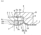
- the joint 2 forms a corner portion 2b and a packing fitting portion 6, which are brought into contact with the other inclined surface 5b of a chevron type projection portion 5 of the thin stainless steel pipe 1, in an inner periphery close to an opening end portion 2a of the joint 2, as shown in Figs. 1 to 6 .
- the packing fitting portion 6 has two inner side surfaces including a packing pressing surface 6a with which a leading end surface 3a of the packing 3 is brought into contact, and a packing outer peripheral contact surface 6b with which an outer peripheral surface 3b of the packing 3 is brought into contact, as is well expressed in Figs. 5 and 6 .
- a release groove 6c is formed in an axial direction of the packing outer peripheral contact surface 6b, from the packing pressing surface 6a to the opening end portion 2a of the joint 2.
- the release groove 6c is provided for leading water existing in a gap in the packing pressing surface 6a and the leading end surface 3a of the packing 3 to a gap S3 formed by a joint contact surface 9 of the nut 4 and the opening end portion 2a of the joint 2, and a part of the packing 3 enters the release groove 6c at a time when the packing 3 is pinched between the packing pressing surface 6a and the joint contact surface 9 of the nut 4 so as to evaginate in a circumferential direction, so that the release groove 6c is sealed.
- the number of the release groove 6c is not particularly limited.
- a magnitude of a width of the release groove 6c is not particularly limited, however, if the magnitude is too small, the evaginating packing 3 is hard to enter and can not seal the groove. Accordingly, the width equal to or more than 1 mm is necessary. Further, if a depth of the groove is too deep, the evaginating packing 3 is hard to enter. Accordingly, it is preferable that the depth of the groove is equal to or less than one quarter a thickness of the packing 3. However, they are decided individually in relation to the width of the groove.
- Fig. 6 shows a case where the fastening between the female thread 8 of the nut 4 and the male thread 7 of the joint 2 is further slack.
- the water passing path of the arrow T shown in Fig. 5 is enlarged, the water widely leaks out to the external portion, and it is possible to easily check out from the external portion that the fastening is insufficient.
- the second embodiment is different from the first embodiment in a point that a projection 6d is formed in place of the release groove 6c in the packing outer peripheral contact surface 6b.
- a gap S is formed between the outer peripheral surface 3b of the packing 3 and the packing outer peripheral contact surface 6b by this projection 6d. If the female thread 8 of the nut 4 is sufficiently fastened to the male thread 7 of the joint 2, the packing 3 is pinched by the joint contact surface 9 of the nut 4 and the packing pressing surface 6a of the joint 2, a volume corresponding to a reduced amount evaginates in an outer peripheral direction, and the gap S is filled. Accordingly, since the water flowing within the thin stainless steel pipe 1 is closed in its passing path, no water leaks out.
- the number of the projection 6d is not particularly limited, however, the packing 3 existing in an inner portion is stably supported by three ormoreprojections. Further, it is desirable that a length of the projection 6d is formed along an entire length in an axial direction of the packing outer peripheral contact surface 6b, however, it is not always necessary to form one continuous projection, but small projections are formed on display so as to be spaced. If a protruding height of the projection 6d is too large, there is a risk that the gap can not be closed by the evagination of the packing 3. Accordingly, it is preferable that the protruding height is equal to or less than one quarter the thickness of the packing 3.
- the packing 3 is pressed into the packing fitting portion 6 of the joint 2, and the end portion of the thin stainless steel pipe 1 is thereafter inserted to the inner portion of the pipe insertion hole 2d of the joint 2. Further, it may screw the male thread 7 formed in the outer periphery of the end portion of the joint 2 and the female thread portion 8 of the nut 4 which is outwardly fitted to the thin stainless steel pipe 1 in advance until the joint contact surface 9 of the nut 4 is brought into contact with the end portion of the joint 2.
- the chevron type projection portion 5 of the thin stainless steel pipe 1 is pinched by the corner portion 2a of the joint 2, the inclined notch portion 10 of the nut 4 and the packing 3 so as to be fixed, and the packing 3 is closely attached to the other inclined surface 5b of the chevron type projection portion 5, the packing fitting portion 6b and the joint contact surface 9, thereby preventing the leakage of the fluid flowing within the thin stainless steel pipe 1. Since the case where the fastening is insufficient is the same as the first embodiment, a description thereof will be omitted.
- This invention can be effectively utilized with respect to a piping such as a water pipe or the like frequently arranged in each of floors of a building.
Description
- This invention relates to a connecting mechanism for a thin stainless steel pipe and a joint which can simply and securely connect the thin stainless steel pipe and the joint in the field and can easily know a flaw of a coupling work.
- This kind of related art includes a structure disclosed in Japanese Utility Model Publication No.
2-37015 Fig. 10 showing a connecting structure for a thin stainless steel pipe and a joint which is obtained by further adding an improvement to this related art, this related art is constructed by a thinstainless steel pipe 1 in which a chevrontype projection portion 5 having twoinclined surfaces joint 2 in which amale thread portion 7 is formed in an outer peripheral surface of an end portion as well as having an inner diameter to which the thinstainless steel pipe 1 is inserted, anut 4 which has afemale thread portion 8 engaging with themale thread portion 7 of thejoint 2 as well as having afitting portion 11 outwardly fitted to the thinstainless steel pipe 1 so as to oppose to thejoint 2 on the boundary of the chevrontype projection portion 5, and apacking 3 which is provided between thejoint 2 and the thinstainless steel pipe 1. - In the
joint 2, there is formed apacking fitting portion 6 for fitting thepacking 3 closely attached to oneinclined surface 5b close to the end portion of the chevrontype projection portion 5 to an inner periphery close to anopen end portion 2a thereof. Further, apipe insertion hole 2d expanded at a thickness of the thinstainless steel pipe 1 for inserting an end portion of the thinstainless steel pipe 1 is formed in both ends of aninner hole 2c in a center portion. - In the
nut 4, there is formed aninclined notch portion 10 closely attached to the otherinclined surface 5a of the chevrontype projection portion 5 in an inner end portion of thefitting portion 11 outwardly fitted to the thinstainless steel pipe 1, and there is formed ajoint contact surface 9 with which theopening end portion 2a of thejoint 2 is brought into contact at a time of screwing and firmly attaching thefemale thread portion 8 of thenut 4 and themale thread portion 7 of thejoint 2. Thejoint contact surface 9 is formed based on an inner diameter difference between thefitting portion 11 and thefemale thread portion 8. - The
packing 3 is formed in such a manner as to be closely attached to each of the oneinclined surface 5b of the chevrontype projection portion 5 formed in the thin stainless steel pipe 1 a time of screwing and firmly attaching thefemale thread portion 8 of thenut 4 and themale thread portion 7 of thejoint 2, thejoint contact surface 9 of thenut 4, and a packing pressingsurface 6a and a packing outerperipheral contact surface 6b corresponding to an inner side surface of thepacking fitting portion 6 of thejoint 2, and is made of an elastic material such as a rubber or the like having an approximately polygonal horizontal cross sectional shape. - The chevron
type projection portion 5 of the thinstainless steel pipe 1 is formed by using a pipe expanding apparatus K, as shown inFig. 11 , and is formed specifically in accordance with the following procedure. First of all, thefemale thread portion 8 of thenut 4 outwardly fitted to the thinstainless steel pipe 1 is screwed and firmly attached to amale thread portion 21 formed in an outer periphery of apipe expanding head 20 fixed to an apparatus (not shown), ashaft 25 outwardly fitting arubber receiver 22, apipe expanding rubber 23 and arubber presser foot 24 is movably inserted from an end portion of the thinstainless steel pipe 1, and a leading end of the thinstainless steel pipe 1 is inserted from an opening portion of thepipe expanding head 20 until it comes into contact with astep wall 20a in an inner portion thereof. Further, therubber receiver 22 is brought into contact with thestep wall 20a of thepipe expanding head 20 by pulling theshaft 25 by an apparatus (not shown) in an arrow direction, and theshaft 25 is pulled in the arrow direction, whereby therubber presser foot 24 is pushed in the arrow direction by alocking portion 26 fixed to a leading end of theshaft 25. At this time, since thepipe expanding rubber 23 pinched by therubber receiver 22 and therubber presser foot 24 is reduced its width, thepipe expanding rubber 23 is expanded at a volume reduced in a circumferential direction. In an outer periphery of the expandedpipe expanding rubber 23, the thinstainless steel pipe 1 is evaginated to a chevron space U in an end portion thereof in accordance with the expansion in the circumferential direction of thepipe expanding rubber 23, as shown inFig. 12 , based on an existence of the chevron space U formed by theinclined notch portion 10 of thenut 4 and anotch portion 20b formed in an inner peripheral surface of a leading end of thepipe expanding head 20, whereby the chevrontype projection portion 5 is formed. Thenut 4 is loosened in this state so as to be detached from thepipe expanding head 20, and there is set a state in which thenut 4 is fitted to an outer periphery of the thinstainless steel 1. Theshaft 25, and therubber receiver 22, thepipe expanding rubber 23 and therubber presser foot 24 which are outwardly fitted to theshaft 25 are drawn out from the thinstainless steel pipe 1. - The connection between the thin
stainless steel pipe 1 and thejoint 2 is achieved first of all by fitting thepacking 3 from the end portion of the thinstainless steel pipe 1 so as to closely attach the fittedpacking 3 to the oneinclined surface 5a, or fitting thepacking 3 into thepacking fitting portion 6 of thejoint 2 and thereafter inserting the end portion of the thinstainless steel pipe 1 to the inner portion of thepipe insertion hole 2d existing in both sides of thejoint 2, as shown in a right half ofFig. 10 . Further, themale thread portion 7 formed in the outer periphery of the end portion of thejoint 2 is connected to thefemale thread portion 8 of thenut 4 outwardly fitted to the thinstainless steel pipe 1 by turning the nut sufficiently in advance until thejoint contact surface 9 comes into contact with theopening end portion 2a of thejoint 2 in a fastening manner. Accordingly, as shown in a left half ofFig. 10 , the chevrontype projection portion 5 of the thinstainless steel pipe 1 is pinched by thecorner portion 2b of thejoint 2, theinclined notch portion 10 of thenut 4 and thepacking 3 so as to be fixed, and thepacking 3 is closely attached to theinclined surface 5b of the chevrontype projection portion 5, thepacking pressing surface 6a and the packing outerperipheral contact surface 6b corresponding to the inner side surface of thepacking fitting portion 6, and thejoint contact surface 9, thereby preventing the leakage of water leaking out from the gap of the connection portion between the thinstainless steel pipe 1 and thejoint 2. - In accordance with the related art mentioned above, since it is hard to discriminate from an outer side even in a case where the
male thread 7 of thenut 4 is not sufficiently fastened to themale thread 7 of thejoint 2 such as a temporal fastening by a manual fastening having a weak fastening force at a time of a piping execution, this matter is often passed over at a time of inspecting a construction finish. Further, a water leak is checked by tentatively circulating a pressure water after the end of the piping construction, however, since thepacking 3 is closely attached to thejoint 2 and theinclined surface 5b of the thinstainless steel pipe 2 even in the manual fastening stage, the water is not so leaked, so that this matter is often passed over. Due to the reason mentioned above, if thenut 4 is started to use in a state where thenut 4 is not sufficiently fastened to thejoint 2, which causes a problem that the connection between thenut 4 and thejoint 2 is detached, and the water leak of the fluid such as the water flowing within the thinstainless steel pipe 1 or the like simultaneously arises, whereby a portion within a building is soiled. - This invention is made for solving the problem mentioned above, and an object of this invention is to provide a connecting mechanism for a thin stainless steel pipe and a joint which can check out a fastening failure and an insufficient fastening at a time of a piping execution for screwing and firmly attaching a male thread portion of a joint to a female thread portion of a nut fitted to a thin stainless steel pipe, based on a leakage of a pressure water.
- In order to achieve the obj ect mentioned above, in accordance with the present invention, there is provided a connecting mechanism for a thin stainless steel pipe and a joint, including: a thin stainless steel pipe in which a chevron type projection portion is formed in an outer periphery of an end portion; a joint having an inner diameter inserting the thin stainless steel pipe and forming a male thread portion in an outer peripheral surface of an end portion; a nut having a fitting portion outwardly fitted to the thin stainless steel pipe so as to oppose to the joint on the boundary of the chevron type projection portion and having a female thread portion screwed to the male thread portion of the joint; a packing provided between the joint and the thin stainless steel pipe; and a chevron type projection portion having two inclined surfaces being formed by expanding the chevron type projection portion of the thin stainless steel pipe based on a uniform force by inflating a rubber inserted to an inner portion of the chevron type projection portion in an outer peripheral direction, a packing fitting portion fitting the packing to an inner periphery of an end portion of the joint being formed in the joint, an inclined notch portion closely attached ton one inclined surface of the chevron type projection portion being formed in an inner end portion of a fitting portion of the nut, a joint contact surface being formed in the nut, the joint contact surface being structured such that an end surface of the joint is brought into contact with the joint contact surface at a time when the female thread portion of the nut and the male thread portion of the joint are screwed and firmly attached, and the joint contact surface is formed based on an inner diameter difference between the fitting portion and the female thread portion, and the packing being formed such as to be closely attached to each of another inclined surface of the chevron type projection portion formed in the thin stainless steel pipe, and a packing pressing surface and a packing outer peripheral contact surface constructing inner side surfaces of the joint contact surface of the nut and the packing fitting portion of the joint at a time when the female thread portion of the nut is screwed and firmly attached to the male thread portion of the joint, wherein a release groove is formed in a packing outer peripheral contact surface from the packing pressing surface constructing the inner side surface of the packing fitting portion of the joint to an opening end portion.
- Further, in accordance with the present invention, there is provided a connecting mechanism for a thin stainless steel pipe and a joint, including: a thin stainless steel pipe in which a chevron type projection portion is formed in an outer periphery of an end portion; a joint having an inner diameter inserting the thin stainless steel pipe and forming a male thread portion in an outer peripheral surface of an end portion; a nut having a fitting portion outwardly fitted to the thin stainless steel pipe so as to oppose to the joint on the boundary of the chevron type projection portion and having a female thread portion screwed to the male thread portion of the joint; a packing provided between the joint and the thin stainless steelpipe; and a chevron type projection portion having two inclined surfaces being formed by expanding the chevron type projection portion of the thin stainless steel pipe based on a uniform force by inflating a rubber inserted to an inner portion of the chevron type projection portion in an outer peripheral direction, a packing fitting portion fitting the packing to an inner periphery of an end portion of the joint being formed in the joint, an inclined notch portion closely attached ton one inclined surface of the chevron type projection portion being formed in an inner end portion of a fitting portion of the nut, a joint contact surface being formed in the nut, the joint contact surface being structured such that an end surface of the joint is brought into contact with the joint contact surface at a time when the female thread portion of the nut and the male thread portion of the joint are screwed and firmly attached, and the joint contact surface is formed based on an inner diameter difference between the fitting portion and the female thread portion, and the packing being formed such as to be closely attached to each of another inclined surface of the chevron type projection portion formed in the thin stainless steel pipe, and a packing pressing surface and a packing outer peripheral contact surface constructing inner side surfaces of the joint contact surface of the nut and the packing fitting portion of the joint at a time when the female thread portion of the nut is screwed and firmly attached to the male thread portion of the joint, wherein a projection is formed in a packing outer peripheral contact surface from the packing pressing surface constructing the inner side surface of the packing fitting portion of the joint to an opening end portion.
- In accordance with the connecting mechanism for the thin stainless steel and the joint based on the first aspect of the present invention, the water intruding into a space generated between the packing pressing surface of the packing fitting portion and the packing passes through the release groove formed in the packing outer peripheral contact surface via the gap between the joint and the thin stainless steel pipe at a position at which the fastening of the nut is insufficient, even in a state in which the outer peripheral surface of the packing is brought into contact with the packing outer peripheral contact surface of the packing fitting portion, thereby leaking out to the external portion from the screwed portion between the nut and the joint or the joint portion between the nut and the thin stainless steel pipe. On the other hand, at a position at which the nut is sufficiently fastened, since the packing pressing surface of the packing fitting portion of the joint presses the packing against the joint contact surface of the nut and the inclined surface of the thin stainless steel pipe so as to stop water, the water in the thin stainless steel pipe does not leak out to the external portion. Further, even if a small space is generated between the packingpressing surface of the packing fittingportion and the packing and the water intrudes thereinto, the packing compressed by fastening the nut evaginates from the packing fitting portion and the release groove is filled up. Accordingly, no water leaks out to the external portion through the release groove. As mentioned above, it is possible to securely find out the position at which the fastening of the nut is insufficient, by circulating the pressure water to the thin stainless steel pipe so as to specify the position at which the water leak is generated. Further, it is preferable to fasten the nut at which the water leaks out.
- Further, in accordance with the connecting mechanism for the thin stainless steel and the joint based on the second aspect of the present invention, the gap corresponding to the height of the projection is generated between the outer peripheral surface of the packing and the packing outer peripheral contact surface constructing the inner side surface of the packing fittingportion, at a position at which the fastening of the nut is insufficient. Accordingly, the water intruding into a space generated between the packing pressing portion of the packing fitting portion projection and the packing passes through the gap corresponding to the height of the projection via the gap between the joint and the thin stainless steel pipe, thereby leaking out to the external portion from the screwed portion between the nut and the joint or the joint portion between the nut and the thin stainless steel pipe. On the other hand, at a position at which the nut is sufficiently fastened, since the packing pressing surface of the packing fitting portion of the joint presses the packing against the joint contact surface of the nut and the inclined surface of the thin stainless steel pipe so as to stop water, the water in the thin stainless steel pipe does not leak out to the external portion. Further, even if a small space is generated between the packing pressing surface of the packing fitting portion and the packing and the water intrudes thereinto, the packing compressed by fastening the nut is deformed, whereby the gap corresponding to the height of the projection is filled up with the packing. Accordingly, no water leaks out to the external portion through the gap. As mentioned above, it is possible to securely find out the position at which the fastening of the nut is insufficient, by circulating the pressure water to the thin stainless steel pipe so as to specify the position at which the water leak is generated. Further, it is preferable to fasten the nut at which the water leaks out.
-
-
Fig. 1 is a schematic vertical cross sectional view showing a coupling structure of a thin stainless steel pipe using a pipe joint in accordance with a first embodiment of the present invention; -
Fig. 2 is a schematic perspective view showing a structure of one end side of the pipe joint in accordance with the first embodiment; -
Fig. 3 is a vertical cross sectional view along a line X-X inFig. 1 ; -
Fig. 4 is a partial enlarged vertical cross sectional view of a portion A inFig. 1 ; -
Fig. 5 is a partial enlarged vertical cross sectional view of a portion B inFig. 1 ; -
Fig. 6 is a partial enlarged vertical cross sectional view in a case where a fastening is further insufficient in comparison with the portion B inFig. 1 ; -
Fig. 7 is a schematic vertical cross sectional view showing a coupling structure of a pipe using a pipe joint in accordance with a second embodiment of the present invention; -
Fig. 8 is a schematic perspective view showing a structure of one end side of the pipe joint in accordance with the second embodiment; -
Fig. 9 is a vertical cross sectional view along a line Y-Y inFig. 7 ; -
Fig. 10 is a schematic vertical cross sectional view showing a coupling structure of a thin stainless steel pipe using a pipe joint in accordance with a related art; -
Fig. 11 is an explanatory view forming a chevron type projection portion in a thin stainless steel pipe; and -
Fig. 12 is an explanatory view forming the chevron type projection portion in the thin stainless steel pipe. - A description will be given below of a preferred embodiment of this invention. This invention is different from the related art in a point that a
joint 2 is improved in such a manner that a water leak is generated in a case where a fastening of anut 4 is insufficient at a time of coupling a thinstainless steel pipe 1 via thejoint 2 and apacking 3 by thenut 4. Since the other constituting elements are the same as the related art, a description thereof will be omitted by attaching the same reference numerals. - The
joint 2 forms acorner portion 2b and apacking fitting portion 6, which are brought into contact with the otherinclined surface 5b of a chevrontype projection portion 5 of the thinstainless steel pipe 1, in an inner periphery close to anopening end portion 2a of thejoint 2, as shown inFigs. 1 to 6 . Thepacking fitting portion 6 has two inner side surfaces including a packing pressingsurface 6a with which a leading end surface 3a of thepacking 3 is brought into contact, and a packing outerperipheral contact surface 6b with which an outerperipheral surface 3b of thepacking 3 is brought into contact, as is well expressed inFigs. 5 and6 . Further, arelease groove 6c is formed in an axial direction of the packing outerperipheral contact surface 6b, from the packing pressingsurface 6a to theopening end portion 2a of thejoint 2. Therelease groove 6c is provided for leading water existing in a gap in thepacking pressing surface 6a and the leading end surface 3a of thepacking 3 to a gap S3 formed by ajoint contact surface 9 of thenut 4 and theopening end portion 2a of thejoint 2, and a part of thepacking 3 enters therelease groove 6c at a time when thepacking 3 is pinched between the packing pressingsurface 6a and thejoint contact surface 9 of thenut 4 so as to evaginate in a circumferential direction, so that therelease groove 6c is sealed. The number of therelease groove 6c is not particularly limited. In a case where a plurality ofrelease grooves 6c are provided, it is preferable to provide the release groove c at a uniform interval. Further, a magnitude of a width of therelease groove 6c is not particularly limited, however, if the magnitude is too small, theevaginating packing 3 is hard to enter and can not seal the groove. Accordingly, the width equal to or more than 1 mm is necessary. Further, if a depth of the groove is too deep, the evaginating packing 3 is hard to enter. Accordingly, it is preferable that the depth of the groove is equal to or less than one quarter a thickness of thepacking 3. However, they are decided individually in relation to the width of the groove. - If a
female thread 8 of thenut 4 and amale thread 7 of the joint 2 are not sufficiently fastened in a temporary fastened state, as shown inFig. 5 , the water flowing in aninner hole 2c of the joint 2 enters the gap S3 formed by the openingend portion 2a of the joint 2 and thejoint contact surface 9 of thenut 4 through therelease groove 6c via a gap S2 between the packingpressing surface 6a of the packingfitting portion 6 and the leading end surface 3a of the packing 3 from a gap S1 between apipe insertion hole 2d of the joint 2 and the thinstainless steel pipe 1, and leaks out to an external portion of the thinstainless steel pipe 1 through a small gap between thefemale thread 8 and themale thread 7, and small gaps between thejoint contact surface 9 of thenut 4 and aninclined notch portion 10 and between the packing 3 and theinclined surface 5a from the gap S3. A passing path of the water at this time is shown by an arrow T inFig. 5 . Accordingly, it is possible to check out from the external portion that the fastening between thenut 4 and the joint 2 is insufficient, in this connecting mechanism. -
Fig. 6 shows a case where the fastening between thefemale thread 8 of thenut 4 and themale thread 7 of the joint 2 is further slack. In this case, since the water passing path of the arrow T shown inFig. 5 is enlarged, the water widely leaks out to the external portion, and it is possible to easily check out from the external portion that the fastening is insufficient. - A description will be given of a second embodiment in accordance with this invention with reference to
Figs. 7 to 9 . The second embodiment is different from the first embodiment in a point that aprojection 6d is formed in place of therelease groove 6c in the packing outerperipheral contact surface 6b. A gap S is formed between the outerperipheral surface 3b of thepacking 3 and the packing outerperipheral contact surface 6b by thisprojection 6d. If thefemale thread 8 of thenut 4 is sufficiently fastened to themale thread 7 of the joint 2, thepacking 3 is pinched by thejoint contact surface 9 of thenut 4 and thepacking pressing surface 6a of the joint 2, a volume corresponding to a reduced amount evaginates in an outer peripheral direction, and the gap S is filled. Accordingly, since the water flowing within the thinstainless steel pipe 1 is closed in its passing path, no water leaks out. - The number of the
projection 6d is not particularly limited, however, the packing 3 existing in an inner portion is stably supported by three ormoreprojections. Further, it is desirable that a length of theprojection 6d is formed along an entire length in an axial direction of the packing outerperipheral contact surface 6b, however, it is not always necessary to form one continuous projection, but small projections are formed on display so as to be spaced. If a protruding height of theprojection 6d is too large, there is a risk that the gap can not be closed by the evagination of thepacking 3. Accordingly, it is preferable that the protruding height is equal to or less than one quarter the thickness of thepacking 3. - In the connection between the thin
stainless steel pipe 1 and the joint 2, first of all, thepacking 3 is pressed into the packingfitting portion 6 of the joint 2, and the end portion of the thinstainless steel pipe 1 is thereafter inserted to the inner portion of thepipe insertion hole 2d of thejoint 2. Further, it may screw themale thread 7 formed in the outer periphery of the end portion of the joint 2 and thefemale thread portion 8 of thenut 4 which is outwardly fitted to the thinstainless steel pipe 1 in advance until thejoint contact surface 9 of thenut 4 is brought into contact with the end portion of thejoint 2. Accordingly, the chevrontype projection portion 5 of the thinstainless steel pipe 1 is pinched by thecorner portion 2a of the joint 2, theinclined notch portion 10 of thenut 4 and thepacking 3 so as to be fixed, and thepacking 3 is closely attached to the otherinclined surface 5b of the chevrontype projection portion 5, the packingfitting portion 6b and thejoint contact surface 9, thereby preventing the leakage of the fluid flowing within the thinstainless steel pipe 1. Since the case where the fastening is insufficient is the same as the first embodiment, a description thereof will be omitted. - This invention can be effectively utilized with respect to a piping such as a water pipe or the like frequently arranged in each of floors of a building.
Claims (2)
- A connecting mechanism for a thin stainless steel pipe (1) and a joint (2), comprising:a thin stainless steel pipe (1) in which a chevron type projection portion (5) is formed in an outer periphery of an end portion;a joint (2) having an inner diameter inserting said thin stainless steel pipe (1) and forming a male thread portion (7) in an outer peripheral surface of an end portion;a nut (4) having a fitting portion (11) outwardly fitted to said thin stainless steel pipe (1) so as to oppose to said joint (2) on the boundary of said chevron type projection portion (5) and having a female thread portion (8) screwed to the male thread portion (7) of the joint (2);a packing (3) provided between said joint (2) and said thin stainless steel pipe (1); andthe chevron type projection portion (5) having two inclined surfaces (5a, 5b) being formed by expanding the chevron type projection portion (5) of said thin stainless steel pipe (1) based on a uniform force by inflating a rubber inserted to an inner portion of the chevron type projection (5) portion in an outer peripheral direction, a packing fitting portion (6) fitting said packing (3) to an inner periphery of an end portion of the joint (2) being formed in said joint (2), an inclined notch portion (10) closely attached to one inclined surface (5a) of said chevron type projection portion (5) being formed in an inner end portion of a fitting portion (11) of said nut (4), a joint contact surface (9) being formed in said nut (4), the joint contact surface (9) being structured such that an end surface of the joint (2) is brought into contact with the joint contact surface (9) at a time when the female thread portion (8) of said nut (4) and the male thread portion (7) of the joint (2) are screwed and firmly attached, and the joint contact surface (9) is formed based on an inner diameter difference between said fitting portion (11) and the female thread portion (8), and said packing (3) being formed such as to be closely attached to each of another inclined surface (5b) of the chevron type projection portion (5) formed in said thin stainless steel pipe (1), and a packing pressing surface (6a) and a packing outer peripheral contact surface (6b) constructing inner side surfaces of the joint contact surface (9) of said nut (4) and the packing fitting portion(6) of the joint (2) at a time when the female thread portion (8) of said nut (4) is screwed and firmly attached to the male thread portion (7) of said joint (2), characterized by a release groove (6c) which is formed in the packing outer peripheral contact surface (6b), starts from the packing pressing surface (6a) constructing the inner side surface of the packing fitting portion (6) of said joint (2) and extends to an opening end portion (2a) of said joint (2).
- A connecting mechanism for a thin stainless steel pipe (1) and a joint (2), comprising:a thin stainless steel pipe (1) in which a chevron type projection portion (5) is formed in an outer periphery of an end portion;a joint (2) having an inner diameter inserting said thin stainless steel pipe (1) and forming a male thread portion (7) in an outer peripheral surface of an end portion;a nut (4) having a fitting portion (11) outwardly fitted to said thin stainless steel pipe (1) so as to oppose to said joint (2) on the boundary of said chevron type projection portion (5) and having a female thread portion (8) screwed to the male thread portion (7) of the joint (2.);a packing (3) provided between said joint (2) and said thin stainless steel pipe (1); andthe chevron type projection portion (5) having two inclined surfaces (5a, 5b) being formed by expanding the chevron type projection portion (5) of said thin stainless steel pipe (1) based on a uniform force by inflating a rubber inserted to an inner portion of the chevron type projection (5) portion in an outer peripheral direction, a packing fitting portion (6) fitting said packing (3) to an inner periphery of an end portion of the joint (2) being formed in said joint (2), an inclined notch portion (10) closely attached to one inclined surface (5a) of said chevron type projection portion (5) being formed in an inner end portion of a fitting portion (11) of said nut (4), a joint contact surface (9) being formed in said nut (4), the joint contact surface (9) being structured such that an end surface of the joint (2) is brought into contact with the joint contact surface (9) at a time when the female thread portion (8) of said nut (4) and the male thread portion (7) of the joint (2) are screwed and firmly attached, and the joint contact surface (9) is formed based on an inner diameter difference between said fitting portion (11) and the female thread portion (8), and said packing (3) being formed such as to be closely attached to each of another inclined surface (5b) of the chevron type projection portion (5) formed in said thin stainless steel pipe (1), and a packing pressing surface (6a) and a packing outer peripheral contact surface (6b) constructing inner side surfaces of the joint contact surface (9) of said nut (4) and the packing fitting portion (6) of the joint (2) at a time when the female thread portion (8) of said nut (4) is screwed and firmly attached to the male thread portion (7) of said joint (2),
characterized bya projection (6d) which is formed in the packing outer peripheral contact surface (6b), starts from the packing pressing surface (6a) constructing the inner side surface of the packing fitting portion (6) of said joint (2) and extends to an opening end portion (2a) of said joint (2).
Applications Claiming Priority (1)
| Application Number | Priority Date | Filing Date | Title |
|---|---|---|---|
| PCT/JP2007/070485 WO2009050823A1 (en) | 2007-10-19 | 2007-10-19 | Connection mechanism between thin-wall stainless steel tube and joint |
Publications (3)
| Publication Number | Publication Date |
|---|---|
| EP2085672A1 EP2085672A1 (en) | 2009-08-05 |
| EP2085672A4 EP2085672A4 (en) | 2010-12-22 |
| EP2085672B1 true EP2085672B1 (en) | 2014-05-21 |
Family
ID=40562725
Family Applications (1)
| Application Number | Title | Priority Date | Filing Date |
|---|---|---|---|
| EP07830219.7A Active EP2085672B1 (en) | 2007-10-19 | 2007-10-19 | Connection mechanism between thin-wall stainless steel tube and joint |
Country Status (7)
| Country | Link |
|---|---|
| US (1) | US7726701B2 (en) |
| EP (1) | EP2085672B1 (en) |
| JP (1) | JPWO2009050823A1 (en) |
| DK (1) | DK2085672T3 (en) |
| ES (1) | ES2488921T3 (en) |
| PT (1) | PT2085672E (en) |
| WO (1) | WO2009050823A1 (en) |
Families Citing this family (17)
| Publication number | Priority date | Publication date | Assignee | Title |
|---|---|---|---|---|
| JP5277507B2 (en) * | 2010-06-04 | 2013-08-28 | セウング ジン インダストリー カンパニー リミテッド | Flexible hose assembly with joint |
| JP5608463B2 (en) * | 2010-08-02 | 2014-10-15 | 株式会社フジキン | Fluid coupling |
| US10890282B2 (en) * | 2014-02-27 | 2021-01-12 | Sundew Technologies, Llc | Face sealed fittings |
| DE202014101748U1 (en) | 2014-04-14 | 2014-04-22 | Ti Automotive (Heidelberg) Gmbh | Screw connection device for connecting two pipes |
| ES2800169T3 (en) * | 2015-10-06 | 2020-12-28 | O N Ind Co Ltd | Connection mechanism for copper pipe and joint |
| SE1551317A1 (en) * | 2015-10-13 | 2017-04-14 | Sapa As | Brake tube connector and brake tube connector assembly |
| GB2544754B (en) * | 2015-11-24 | 2018-11-07 | Self Energising Coupling Co Ltd | Improved fluid coupling |
| US10584814B2 (en) * | 2016-03-23 | 2020-03-10 | Swagelok Company | Conduit fitting with stroke resisting features |
| JP2017115577A (en) * | 2017-03-30 | 2017-06-29 | Jfeスチール株式会社 | Bonded joint of steel pipe |
| US11519529B2 (en) * | 2017-05-31 | 2022-12-06 | Hanon Systems | Metal sealing threaded (tube-o) fitting |
| CN107035924A (en) * | 2017-06-01 | 2017-08-11 | 曾广新 | Built-in sealed connection unit, component and pipe-line system |
| CN107869616A (en) * | 2017-11-30 | 2018-04-03 | 信宜市家加美不锈钢制品有限公司 | A kind of conveniently and solidly stainless steel water pipe connecting structure |
| JP7017233B2 (en) * | 2018-02-28 | 2022-02-08 | オーエヌ工業株式会社 | Thin-walled stainless steel pipe expansion device |
| US20190360648A1 (en) * | 2018-05-22 | 2019-11-28 | Habitex Corporation | Lighting assembly |
| JPWO2022003894A1 (en) * | 2020-07-02 | 2022-01-06 | ||
| JP7230264B1 (en) | 2022-06-29 | 2023-02-28 | オーエヌ工業株式会社 | Connection mechanism for steel pipes and fittings |
| TWI815756B (en) * | 2022-12-22 | 2023-09-11 | 中鴻鋼鐵股份有限公司 | Anti-corrosion multilayers pipe |
Family Cites Families (39)
| Publication number | Priority date | Publication date | Assignee | Title |
|---|---|---|---|---|
| US771682A (en) * | 1904-03-26 | 1904-10-04 | Leon Sussman | Pipe-joint. |
| US1058542A (en) * | 1912-10-01 | 1913-04-08 | Sydney L Brown | Pipe-coupling. |
| US1664125A (en) * | 1926-11-10 | 1928-03-27 | John R Lowrey | Hose coupling |
| US1782737A (en) * | 1927-01-19 | 1930-11-25 | Lee H Mahon | Casing suspension head |
| US2082164A (en) * | 1934-03-13 | 1937-06-01 | Cons Gas Electric Light And Po | Tube fitting |
| US2323099A (en) * | 1941-12-05 | 1943-06-29 | Patten Walter Evans | Tube fitting |
| US2453391A (en) * | 1946-01-14 | 1948-11-09 | New York Air Brake Co | Tubing connection |
| US2448888A (en) * | 1946-04-05 | 1948-09-07 | Chicago Forging & Mfg Co | Fitting |
| US2685461A (en) * | 1949-09-22 | 1954-08-03 | Mueller Co | Pipe coupling |
| US3258279A (en) * | 1964-11-30 | 1966-06-28 | Robert R Rcddy | Connector seal |
| US3288494A (en) * | 1965-08-11 | 1966-11-29 | Cajon Co | Union coupling |
| US3393930A (en) * | 1966-08-18 | 1968-07-23 | Parker Hannifin Corp | Coupling for thin-walled tubes |
| US3584900A (en) * | 1968-09-18 | 1971-06-15 | Sno Trik Co | High-pressure sealing and gripping device |
| US3807773A (en) * | 1971-12-02 | 1974-04-30 | H Brune | Conduit union and gasket |
| JPS56149186U (en) * | 1980-04-08 | 1981-11-09 | ||
| JPS59107390U (en) * | 1983-01-10 | 1984-07-19 | オ−エヌ工業株式会社 | Connection mechanism of thin-walled stainless steel pipe and fittings |
| JPS62188687U (en) * | 1986-05-22 | 1987-12-01 | ||
| JPH01199089A (en) * | 1988-02-02 | 1989-08-10 | Nec Corp | Fitting with metal c-ring fixing mechanism |
| WO1989011058A1 (en) * | 1988-05-09 | 1989-11-16 | O.N. Industries Co., Ltd. | Connection mechanism for thin-walled stainless steel pipes and joint |
| JP2770332B2 (en) | 1988-07-27 | 1998-07-02 | 日産自動車株式会社 | Vehicle suspension control device |
| JPH06235484A (en) * | 1993-02-05 | 1994-08-23 | Teikoku Kinzoku Kk | Coupler part of sprinkler winding out piping |
| US5529349A (en) * | 1993-08-25 | 1996-06-25 | Itt Corporation | Mounting apparatus with reduced resistance bead seal |
| DE19526316C3 (en) * | 1995-07-19 | 2002-03-07 | Walterscheid Gmbh Jean | pipe connection |
| CN1196784A (en) * | 1995-08-16 | 1998-10-21 | 曼弗雷德·弗勒利希 | High-pressure connection system |
| DE19742917C2 (en) * | 1997-09-29 | 2002-11-14 | Walterscheid Gmbh Jean | Screw connection with support ring |
| DE19951460C2 (en) * | 1999-10-26 | 2001-09-27 | Walterscheid Gmbh Jean | Pipe connection with a connecting section molded onto the pipe |
| DE19958475A1 (en) * | 1999-11-30 | 2001-06-13 | Parker Hannifin Gmbh | Pipe connection and process for its manufacture |
| US6527304B1 (en) * | 2000-02-17 | 2003-03-04 | Ford Global Technologies, Inc. | Brake tube connector |
| JP4463434B2 (en) * | 2001-01-16 | 2010-05-19 | 株式会社オンダ製作所 | Incore |
| JP3682408B2 (en) * | 2001-02-16 | 2005-08-10 | 株式会社オンダ製作所 | Fitting |
| DE10124874A1 (en) * | 2001-05-22 | 2002-11-28 | Voss Fluidtechnik Gmbh & Co Kg | Tube Fitting |
| WO2003056227A1 (en) * | 2001-12-25 | 2003-07-10 | Mirai Industry Co., Ltd. | End part structure of water passing tube, water passing tube with the end part structure, structure of connection between water passing tube and connection body, and method of forming end part structure of water passing tube |
| FR2856132B1 (en) * | 2003-06-10 | 2005-07-22 | Comap | VARIABLE DEPTH GROOVING FITTING FITTING EMBODY DEVICE |
| US6877781B2 (en) * | 2003-07-31 | 2005-04-12 | Highlands Corporation | Corrugated tube fitting |
| JP2005090531A (en) * | 2003-09-12 | 2005-04-07 | Mym Corp | Pipe joint |
| US6988748B2 (en) * | 2003-12-23 | 2006-01-24 | Martinrea Industries, Inc. | Fluid coupling assembly |
| DE102004059909A1 (en) * | 2004-12-13 | 2006-06-14 | Robert Bosch Gmbh | Pipe gland and union nut, connecting piece and pipe for a pipe fitting |
| US20070024054A1 (en) * | 2005-07-27 | 2007-02-01 | Chung Cheng Faucet Co., Ltd. | Tube connection structure |
| JP2007100847A (en) * | 2005-10-04 | 2007-04-19 | On Industries Ltd | Packing and joint-steel pipe connection mechanism |
-
2007
- 2007-10-19 PT PT78302197T patent/PT2085672E/en unknown
- 2007-10-19 JP JP2009537838A patent/JPWO2009050823A1/en active Pending
- 2007-10-19 WO PCT/JP2007/070485 patent/WO2009050823A1/en active Application Filing
- 2007-10-19 EP EP07830219.7A patent/EP2085672B1/en active Active
- 2007-10-19 ES ES07830219.7T patent/ES2488921T3/en active Active
- 2007-10-19 DK DK07830219.7T patent/DK2085672T3/en active
-
2008
- 2008-09-18 US US12/212,747 patent/US7726701B2/en active Active
Also Published As
| Publication number | Publication date |
|---|---|
| US20090102190A1 (en) | 2009-04-23 |
| EP2085672A1 (en) | 2009-08-05 |
| PT2085672E (en) | 2014-07-18 |
| ES2488921T3 (en) | 2014-09-01 |
| DK2085672T3 (en) | 2014-09-01 |
| EP2085672A4 (en) | 2010-12-22 |
| WO2009050823A1 (en) | 2009-04-23 |
| US7726701B2 (en) | 2010-06-01 |
| JPWO2009050823A1 (en) | 2011-02-24 |
Similar Documents
| Publication | Publication Date | Title |
|---|---|---|
| EP2085672B1 (en) | Connection mechanism between thin-wall stainless steel tube and joint | |
| US8585100B2 (en) | Press-connect fitting with improved grab ring function | |
| KR20130052967A (en) | A pipe connector | |
| JP4827171B2 (en) | Pipe end blocking method using pipe stoppers | |
| EP3770475B1 (en) | Pipe joint and method for joining pipes | |
| KR101104085B1 (en) | A pipe connector | |
| JP2006322542A (en) | Pipe joint | |
| JP5192979B2 (en) | Pipe joint structure | |
| KR200437907Y1 (en) | Pipe connecting device of air conditioner | |
| JP2016142293A (en) | Connection mechanism of thin wall stainless steel pipe and joint | |
| JP4597889B2 (en) | Pipe fitting | |
| JP4671645B2 (en) | Detachment prevention fitting | |
| US5199750A (en) | Snake tail ring socket | |
| KR101351201B1 (en) | Pipe fastening apparatus and method | |
| KR101673243B1 (en) | A connector of stainless pipes with hinge and stainless pipe assembly using it | |
| KR20070079965A (en) | Insertting type double contacting joint | |
| KR101209622B1 (en) | Packing and joint and connector of steel pipe | |
| JP2014185674A (en) | Connection mechanism of thin stainless steel pipe and joint | |
| JP6764668B2 (en) | Pipe fittings and pipe joining methods | |
| KR101783524B1 (en) | Connecting structure of coupling pipe | |
| KR20080101811A (en) | Pipe fitting | |
| JP5947586B2 (en) | Case body connection method | |
| JP2005195065A (en) | Pipe connector | |
| JP2009185891A (en) | One-bolt-joint type pipe joint | |
| KR100694246B1 (en) | Connecting structure of connecting pipe and underground pipe of manhole |
Legal Events
| Date | Code | Title | Description |
|---|---|---|---|
| PUAI | Public reference made under article 153(3) epc to a published international application that has entered the european phase |
Free format text: ORIGINAL CODE: 0009012 |
|
| 17P | Request for examination filed |
Effective date: 20081108 |
|
| AK | Designated contracting states |
Kind code of ref document: A1 Designated state(s): AT BE BG CH CY CZ DE DK EE ES FI FR GB GR HU IE IS IT LI LT LU LV MC MT NL PL PT RO SE SI SK TR |
|
| AX | Request for extension of the european patent |
Extension state: AL BA HR MK RS |
|
| RBV | Designated contracting states (corrected) |
Designated state(s): AT BE BG CH CY CZ DE DK EE ES FI FR GB GR HU IE IS IT LI LT LU LV MC MT NL PL PT RO SE SI SK TR |
|
| A4 | Supplementary search report drawn up and despatched |
Effective date: 20101122 |
|
| DAX | Request for extension of the european patent (deleted) | ||
| 17Q | First examination report despatched |
Effective date: 20120413 |
|
| REG | Reference to a national code |
Ref country code: DE Ref legal event code: R079 Ref document number: 602007036885 Country of ref document: DE Free format text: PREVIOUS MAIN CLASS: F16L0019000000 Ipc: F16L0019028000 |
|
| RIC1 | Information provided on ipc code assigned before grant |
Ipc: F16L 19/028 20060101AFI20131203BHEP |
|
| GRAP | Despatch of communication of intention to grant a patent |
Free format text: ORIGINAL CODE: EPIDOSNIGR1 |
|
| INTG | Intention to grant announced |
Effective date: 20140217 |
|
| GRAS | Grant fee paid |
Free format text: ORIGINAL CODE: EPIDOSNIGR3 |
|
| GRAA | (expected) grant |
Free format text: ORIGINAL CODE: 0009210 |
|
| AK | Designated contracting states |
Kind code of ref document: B1 Designated state(s): AT BE BG CH CY CZ DE DK EE ES FI FR GB GR HU IE IS IT LI LT LU LV MC MT NL PL PT RO SE SI SK TR |
|
| REG | Reference to a national code |
Ref country code: GB Ref legal event code: FG4D |
|
| REG | Reference to a national code |
Ref country code: CH Ref legal event code: EP |
|
| REG | Reference to a national code |
Ref country code: AT Ref legal event code: REF Ref document number: 669780 Country of ref document: AT Kind code of ref document: T Effective date: 20140615 |
|
| REG | Reference to a national code |
Ref country code: IE Ref legal event code: FG4D |
|
| REG | Reference to a national code |
Ref country code: DE Ref legal event code: R096 Ref document number: 602007036885 Country of ref document: DE Effective date: 20140703 |
|
| REG | Reference to a national code |
Ref country code: NL Ref legal event code: T3 |
|
| REG | Reference to a national code |
Ref country code: PT Ref legal event code: SC4A Free format text: AVAILABILITY OF NATIONAL TRANSLATION Effective date: 20140708 |
|
| REG | Reference to a national code |
Ref country code: DK Ref legal event code: T3 Effective date: 20140825 Ref country code: ES Ref legal event code: FG2A Ref document number: 2488921 Country of ref document: ES Kind code of ref document: T3 Effective date: 20140901 |
|
| REG | Reference to a national code |
Ref country code: SE Ref legal event code: TRGR |
|
| REG | Reference to a national code |
Ref country code: AT Ref legal event code: MK05 Ref document number: 669780 Country of ref document: AT Kind code of ref document: T Effective date: 20140521 |
|
| REG | Reference to a national code |
Ref country code: LT Ref legal event code: MG4D |
|
| PG25 | Lapsed in a contracting state [announced via postgrant information from national office to epo] |
Ref country code: GR Free format text: LAPSE BECAUSE OF FAILURE TO SUBMIT A TRANSLATION OF THE DESCRIPTION OR TO PAY THE FEE WITHIN THE PRESCRIBED TIME-LIMIT Effective date: 20140822 Ref country code: FI Free format text: LAPSE BECAUSE OF FAILURE TO SUBMIT A TRANSLATION OF THE DESCRIPTION OR TO PAY THE FEE WITHIN THE PRESCRIBED TIME-LIMIT Effective date: 20140521 Ref country code: IS Free format text: LAPSE BECAUSE OF FAILURE TO SUBMIT A TRANSLATION OF THE DESCRIPTION OR TO PAY THE FEE WITHIN THE PRESCRIBED TIME-LIMIT Effective date: 20140921 Ref country code: LT Free format text: LAPSE BECAUSE OF FAILURE TO SUBMIT A TRANSLATION OF THE DESCRIPTION OR TO PAY THE FEE WITHIN THE PRESCRIBED TIME-LIMIT Effective date: 20140521 |
|
| PG25 | Lapsed in a contracting state [announced via postgrant information from national office to epo] |
Ref country code: LV Free format text: LAPSE BECAUSE OF FAILURE TO SUBMIT A TRANSLATION OF THE DESCRIPTION OR TO PAY THE FEE WITHIN THE PRESCRIBED TIME-LIMIT Effective date: 20140521 Ref country code: PL Free format text: LAPSE BECAUSE OF FAILURE TO SUBMIT A TRANSLATION OF THE DESCRIPTION OR TO PAY THE FEE WITHIN THE PRESCRIBED TIME-LIMIT Effective date: 20140521 Ref country code: AT Free format text: LAPSE BECAUSE OF FAILURE TO SUBMIT A TRANSLATION OF THE DESCRIPTION OR TO PAY THE FEE WITHIN THE PRESCRIBED TIME-LIMIT Effective date: 20140521 |
|
| PG25 | Lapsed in a contracting state [announced via postgrant information from national office to epo] |
Ref country code: CZ Free format text: LAPSE BECAUSE OF FAILURE TO SUBMIT A TRANSLATION OF THE DESCRIPTION OR TO PAY THE FEE WITHIN THE PRESCRIBED TIME-LIMIT Effective date: 20140521 Ref country code: SK Free format text: LAPSE BECAUSE OF FAILURE TO SUBMIT A TRANSLATION OF THE DESCRIPTION OR TO PAY THE FEE WITHIN THE PRESCRIBED TIME-LIMIT Effective date: 20140521 Ref country code: BE Free format text: LAPSE BECAUSE OF FAILURE TO SUBMIT A TRANSLATION OF THE DESCRIPTION OR TO PAY THE FEE WITHIN THE PRESCRIBED TIME-LIMIT Effective date: 20140521 Ref country code: EE Free format text: LAPSE BECAUSE OF FAILURE TO SUBMIT A TRANSLATION OF THE DESCRIPTION OR TO PAY THE FEE WITHIN THE PRESCRIBED TIME-LIMIT Effective date: 20140521 Ref country code: RO Free format text: LAPSE BECAUSE OF FAILURE TO SUBMIT A TRANSLATION OF THE DESCRIPTION OR TO PAY THE FEE WITHIN THE PRESCRIBED TIME-LIMIT Effective date: 20140521 |
|
| REG | Reference to a national code |
Ref country code: DE Ref legal event code: R097 Ref document number: 602007036885 Country of ref document: DE |
|
| PLBE | No opposition filed within time limit |
Free format text: ORIGINAL CODE: 0009261 |
|
| STAA | Information on the status of an ep patent application or granted ep patent |
Free format text: STATUS: NO OPPOSITION FILED WITHIN TIME LIMIT |
|
| 26N | No opposition filed |
Effective date: 20150224 |
|
| PG25 | Lapsed in a contracting state [announced via postgrant information from national office to epo] |
Ref country code: LU Free format text: LAPSE BECAUSE OF FAILURE TO SUBMIT A TRANSLATION OF THE DESCRIPTION OR TO PAY THE FEE WITHIN THE PRESCRIBED TIME-LIMIT Effective date: 20141019 Ref country code: MC Free format text: LAPSE BECAUSE OF FAILURE TO SUBMIT A TRANSLATION OF THE DESCRIPTION OR TO PAY THE FEE WITHIN THE PRESCRIBED TIME-LIMIT Effective date: 20140521 |
|
| REG | Reference to a national code |
Ref country code: CH Ref legal event code: PL |
|
| REG | Reference to a national code |
Ref country code: DE Ref legal event code: R097 Ref document number: 602007036885 Country of ref document: DE Effective date: 20150224 |
|
| REG | Reference to a national code |
Ref country code: IE Ref legal event code: MM4A |
|
| PG25 | Lapsed in a contracting state [announced via postgrant information from national office to epo] |
Ref country code: SI Free format text: LAPSE BECAUSE OF FAILURE TO SUBMIT A TRANSLATION OF THE DESCRIPTION OR TO PAY THE FEE WITHIN THE PRESCRIBED TIME-LIMIT Effective date: 20140521 Ref country code: LI Free format text: LAPSE BECAUSE OF NON-PAYMENT OF DUE FEES Effective date: 20141031 Ref country code: CH Free format text: LAPSE BECAUSE OF NON-PAYMENT OF DUE FEES Effective date: 20141031 |
|
| REG | Reference to a national code |
Ref country code: FR Ref legal event code: PLFP Year of fee payment: 9 |
|
| PG25 | Lapsed in a contracting state [announced via postgrant information from national office to epo] |
Ref country code: IE Free format text: LAPSE BECAUSE OF NON-PAYMENT OF DUE FEES Effective date: 20141019 |
|
| PG25 | Lapsed in a contracting state [announced via postgrant information from national office to epo] |
Ref country code: BG Free format text: LAPSE BECAUSE OF FAILURE TO SUBMIT A TRANSLATION OF THE DESCRIPTION OR TO PAY THE FEE WITHIN THE PRESCRIBED TIME-LIMIT Effective date: 20140521 |
|
| PG25 | Lapsed in a contracting state [announced via postgrant information from national office to epo] |
Ref country code: CY Free format text: LAPSE BECAUSE OF FAILURE TO SUBMIT A TRANSLATION OF THE DESCRIPTION OR TO PAY THE FEE WITHIN THE PRESCRIBED TIME-LIMIT Effective date: 20140521 |
|
| PG25 | Lapsed in a contracting state [announced via postgrant information from national office to epo] |
Ref country code: MT Free format text: LAPSE BECAUSE OF FAILURE TO SUBMIT A TRANSLATION OF THE DESCRIPTION OR TO PAY THE FEE WITHIN THE PRESCRIBED TIME-LIMIT Effective date: 20140521 Ref country code: HU Free format text: LAPSE BECAUSE OF FAILURE TO SUBMIT A TRANSLATION OF THE DESCRIPTION OR TO PAY THE FEE WITHIN THE PRESCRIBED TIME-LIMIT; INVALID AB INITIO Effective date: 20071019 |
|
| REG | Reference to a national code |
Ref country code: FR Ref legal event code: PLFP Year of fee payment: 10 |
|
| REG | Reference to a national code |
Ref country code: FR Ref legal event code: PLFP Year of fee payment: 11 |
|
| REG | Reference to a national code |
Ref country code: FR Ref legal event code: PLFP Year of fee payment: 12 |
|
| PGFP | Annual fee paid to national office [announced via postgrant information from national office to epo] |
Ref country code: NL Payment date: 20231023 Year of fee payment: 17 |
|
| PGFP | Annual fee paid to national office [announced via postgrant information from national office to epo] |
Ref country code: GB Payment date: 20231025 Year of fee payment: 17 |
|
| PGFP | Annual fee paid to national office [announced via postgrant information from national office to epo] |
Ref country code: ES Payment date: 20231117 Year of fee payment: 17 |
|
| PGFP | Annual fee paid to national office [announced via postgrant information from national office to epo] |
Ref country code: TR Payment date: 20231012 Year of fee payment: 17 Ref country code: SE Payment date: 20231025 Year of fee payment: 17 Ref country code: PT Payment date: 20231016 Year of fee payment: 17 Ref country code: IT Payment date: 20231031 Year of fee payment: 17 Ref country code: FR Payment date: 20231023 Year of fee payment: 17 Ref country code: DK Payment date: 20231025 Year of fee payment: 17 Ref country code: DE Payment date: 20231208 Year of fee payment: 17 |