JP5277507B2 - ジョイントを備えたフレキシブルホース組立体 - Google Patents
ジョイントを備えたフレキシブルホース組立体 Download PDFInfo
- Publication number
- JP5277507B2 JP5277507B2 JP2010163979A JP2010163979A JP5277507B2 JP 5277507 B2 JP5277507 B2 JP 5277507B2 JP 2010163979 A JP2010163979 A JP 2010163979A JP 2010163979 A JP2010163979 A JP 2010163979A JP 5277507 B2 JP5277507 B2 JP 5277507B2
- Authority
- JP
- Japan
- Prior art keywords
- flexible hose
- adapter
- extension
- bellows pipe
- hose assembly
- Prior art date
- Legal status (The legal status is an assumption and is not a legal conclusion. Google has not performed a legal analysis and makes no representation as to the accuracy of the status listed.)
- Expired - Fee Related
Links
Images


Classifications
-
- F—MECHANICAL ENGINEERING; LIGHTING; HEATING; WEAPONS; BLASTING
- F16—ENGINEERING ELEMENTS AND UNITS; GENERAL MEASURES FOR PRODUCING AND MAINTAINING EFFECTIVE FUNCTIONING OF MACHINES OR INSTALLATIONS; THERMAL INSULATION IN GENERAL
- F16L—PIPES; JOINTS OR FITTINGS FOR PIPES; SUPPORTS FOR PIPES, CABLES OR PROTECTIVE TUBING; MEANS FOR THERMAL INSULATION IN GENERAL
- F16L19/00—Joints in which sealing surfaces are pressed together by means of a member, e.g. a swivel nut, screwed on or into one of the joint parts
- F16L19/02—Pipe ends provided with collars or flanges, integral with the pipe or not, pressed together by a screwed member
- F16L19/025—Pipe ends provided with collars or flanges, integral with the pipe or not, pressed together by a screwed member the pipe ends having integral collars or flanges
- F16L19/028—Pipe ends provided with collars or flanges, integral with the pipe or not, pressed together by a screwed member the pipe ends having integral collars or flanges the collars or flanges being obtained by deformation of the pipe wall
-
- F—MECHANICAL ENGINEERING; LIGHTING; HEATING; WEAPONS; BLASTING
- F16—ENGINEERING ELEMENTS AND UNITS; GENERAL MEASURES FOR PRODUCING AND MAINTAINING EFFECTIVE FUNCTIONING OF MACHINES OR INSTALLATIONS; THERMAL INSULATION IN GENERAL
- F16L—PIPES; JOINTS OR FITTINGS FOR PIPES; SUPPORTS FOR PIPES, CABLES OR PROTECTIVE TUBING; MEANS FOR THERMAL INSULATION IN GENERAL
- F16L35/00—Special arrangements used in connection with end fittings of hoses, e.g. safety or protecting devices
-
- H—ELECTRICITY
- H02—GENERATION; CONVERSION OR DISTRIBUTION OF ELECTRIC POWER
- H02G—INSTALLATION OF ELECTRIC CABLES OR LINES, OR OF COMBINED OPTICAL AND ELECTRIC CABLES OR LINES
- H02G3/00—Installations of electric cables or lines or protective tubing therefor in or on buildings, equivalent structures or vehicles
- H02G3/02—Details
- H02G3/04—Protective tubing or conduits, e.g. cable ladders or cable troughs
- H02G3/0462—Tubings, i.e. having a closed section
- H02G3/0481—Tubings, i.e. having a closed section with a circular cross-section
-
- H—ELECTRICITY
- H02—GENERATION; CONVERSION OR DISTRIBUTION OF ELECTRIC POWER
- H02G—INSTALLATION OF ELECTRIC CABLES OR LINES, OR OF COMBINED OPTICAL AND ELECTRIC CABLES OR LINES
- H02G9/00—Installations of electric cables or lines in or on the ground or water
- H02G9/06—Installations of electric cables or lines in or on the ground or water in underground tubes or conduits; Tubes or conduits therefor
Description
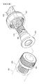
3 ブレード
4 アダプタ
5 カップリングナット
6 連結具
7 スリーブリング
20 延長部
22 フランジ
61 第1結着部
63 第1環溝
65 溝
72 第2結着部
74 第2環溝
Claims (12)
- 一側端部に所定の長さを有する延長管が一体形成され、上記延長管との間に外側に突出したフランジ(22)が形成されたベローズ管(2)と、
前記ベローズ管(2)に結合され、前記フランジ(22)により離脱を防止するカップリングナット(5)と、
前記ベローズ管(2)に結合されて前記フランジ(22)に支持され、前記カップリングナット(5)とねじ結合される連結具(6)と、を含み、
前記延長部(20)の外周面と前記連結具(6)の内周面との間に隙間S1が形成され、前記ベローズ管(2)から漏洩したガスが前記隙間S1を通じて前記延長部(20)の外面に沿って流動した後、前記連結具(6)とカップリングナット(5)のねじ結合部位を通じて排出されることを特徴とするジョイントを備えたフレキシブルホース組立体。 - 前記延長部(20)には真円を有するスリーブ(9)が結合されたことを特徴とする請求項1に記載のジョイントを備えたフレキシブルホース組立体。
- 前記ベローズ管(2)の外面にブレード(3)が被覆され、前記ブレード(3)の外部にアダプタ(4)が結合されることを特徴とする請求項1に記載のジョイントを備えたフレキシブルホース組立体。
- 前記アダプタ(4)に対応するベローズ管(2)の内周面を外側に拡管させてブレード(3)がアダプタ(4)の内面に圧着されるようにしたことを特徴とする請求項3に記載のジョイントを備えたフレキシブルホース組立体。
- 前記連結具(6)の内側には通孔(60)が形成され、両側の外周面にはねじ部(67a、67b)が各々形成され、
前記通孔(60)の入口側の周辺には前記ベローズ管(2)のフランジ(22)が安着するように第1環状溝(63)が形成されたことを特徴とする請求項1に記載のジョイントを備えたフレキシブルホース組立体。 - 一側端部に所定の長さを有する延長部が一体形成され、前記延長部との間に外側に突出するフランジ(22)が形成されたベローズ管(2)と、
前記ベローズ管(2)の端部の外部に結合されたアダプタ(4)と、前記アダプタ(4)の外部に挿入されるカップリングナット(5)と、前記アダプタ(4)の前面に密着し、前記カップリングナット(5)と結合される連結具(6)と、前記ベローズ管(2)のフランジ(22)に支持され、前記カップリングナット(5)の内側に挿入され、前記連結具(6)と密着する中間リング(7)から構成されたカップリング部材と、を含み、
前記連結具(6)の内周面には多数のスロット(65)が形成され、
前記延長部(20)の外周面と前記連結具(6)の内周面との間に隙間S5が形成され、
前記ベローズ管から流出されるガスは、前記スロット(65)と隙間S5を経由して外部に排出されることを特徴とするジョイントを備えたフレキシブルホース組立体。 - 前記ベローズ管(2)の外面にブレード(3)が被覆され、前記ブレード(3)の外部にアダプタ(4)が付着されたことを特徴とする請求項6に記載のジョイントを備えたフレキシブルホース組立体。
- 前記アダプタ(4)に対応するベローズ管(2)の内周面を外側に拡管させてブレード(3)がアダプタ(4)の内面に圧着するようにしたことを特徴とする請求項7に記載のジョイントを備えたフレキシブルホース組立体。
- 前記中間リング(7)は、前記フランジと前記アダプタとの間に配置され、前記フランジ(22)を収容する第2環状溝(74)が形成されたことを特徴とする請求項7に記載のジョイントを備えたフレキシブルホース組立体。
- 前記連結具(6)の内側には前記ベローズ管(2)の延長部(20)が挟まれる通孔(60)が形成され、両側の外周面にはねじ部(67a、67b)が各々形成され、
前記通孔(60)の入口側の周辺には前記ベローズ管(2)のフランジ(22)が安着するように第1環状溝(63)が形成されたことを特徴とする請求項6に記載のジョイントを備えたフレキシブルホース組立体。 - 前記連結具(6)には同心円形態の溝と突起とからなる第1結着部(61)が形成され、
前記中間リング(7)には前記第1結着部(61)と結合されるように同心円形態の溝と突起とからなる第2結着部(72)が形成され、
前記第1及び第2結着部(61、72)の結合時、それらの間に隙間S6が形成されることを特徴とする請求項6に記載のジョイントを備えたフレキシブルホース組立体。 - 前記延長部(20)には真円を有するスリーブ(9)が結合されたことを特徴とする請求項6に記載のジョイントを備えたフレキシブルホース組立体。
Applications Claiming Priority (4)
| Application Number | Priority Date | Filing Date | Title |
|---|---|---|---|
| KR1020100052710A KR100988279B1 (ko) | 2010-06-04 | 2010-06-04 | 방폭용 플렉시블 조인트 장치 |
| KR10-2010-0052710 | 2010-06-04 | ||
| KR10-2010-0059024 | 2010-06-22 | ||
| KR1020100059024A KR100988284B1 (ko) | 2010-06-22 | 2010-06-22 | 조인트를 구비한 플렉시블 호스 조립체 |
Publications (3)
| Publication Number | Publication Date |
|---|---|
| JP2011256997A JP2011256997A (ja) | 2011-12-22 |
| JP2011256997A5 JP2011256997A5 (ja) | 2012-12-27 |
| JP5277507B2 true JP5277507B2 (ja) | 2013-08-28 |
Family
ID=45063537
Family Applications (1)
| Application Number | Title | Priority Date | Filing Date |
|---|---|---|---|
| JP2010163979A Expired - Fee Related JP5277507B2 (ja) | 2010-06-04 | 2010-07-21 | ジョイントを備えたフレキシブルホース組立体 |
Country Status (2)
| Country | Link |
|---|---|
| US (1) | US8523239B2 (ja) |
| JP (1) | JP5277507B2 (ja) |
Families Citing this family (7)
| Publication number | Priority date | Publication date | Assignee | Title |
|---|---|---|---|---|
| US9759364B2 (en) * | 2013-01-22 | 2017-09-12 | Straham Valves, Inc. | Armored hose assembly |
| USD731033S1 (en) * | 2014-02-13 | 2015-06-02 | Neoperl Gmbh | Flexible hose with hose connection or hose fittings |
| US10070882B2 (en) | 2014-08-20 | 2018-09-11 | Gyrus Acmi, Inc. | Apparatus and method for cutting tissue |
| CH712556A2 (de) * | 2016-06-07 | 2017-12-15 | Aborra Ag | Rohrleitungsfitting mit Schwingungskompensator. |
| CN106439484B (zh) * | 2016-07-01 | 2019-07-12 | 韩培 | 低温船用双管装卸臂 |
| KR20180089830A (ko) * | 2017-02-01 | 2018-08-09 | 한일튜브 주식회사 | 차량용 가스연료 배관 |
| CN111946913A (zh) * | 2020-09-07 | 2020-11-17 | 兰州天亿石化设备维修技术有限公司 | 一种天然气管输防爆金属软管 |
Family Cites Families (19)
| Publication number | Priority date | Publication date | Assignee | Title |
|---|---|---|---|---|
| US1539327A (en) * | 1923-06-16 | 1925-05-26 | Internat Metal Hose Company In | Hose coupling |
| US1809874A (en) * | 1925-01-12 | 1931-06-16 | Titeflex Metal Hose Co | Hose coupling |
| US2848254A (en) * | 1950-05-01 | 1958-08-19 | Millar John Humphrey | End fittings for flexible metallic hose |
| US2858147A (en) * | 1954-04-21 | 1958-10-28 | Titeflex Inc | Renewable fitting for reinforced metallic hose |
| US3584900A (en) * | 1968-09-18 | 1971-06-15 | Sno Trik Co | High-pressure sealing and gripping device |
| DE2541242A1 (de) * | 1975-09-12 | 1977-03-24 | Kabel Metallwerke Ghh | Armatur fuer eine wellrohrleitung |
| JPS5846835Y2 (ja) * | 1980-02-22 | 1983-10-25 | 五十鈴工業株式会社 | 導管 |
| JPH0776595B2 (ja) * | 1992-06-25 | 1995-08-16 | 工業技術院長 | 二重管用管継手 |
| JPH06159571A (ja) * | 1992-09-03 | 1994-06-07 | Hitachi Metals Ltd | ガラス繊維ブレードを外装した金属フレキホース |
| JPH0818089B2 (ja) * | 1993-02-02 | 1996-02-28 | トーフレ株式会社 | フレキシブルチューブとその製造方法 |
| JP2689095B2 (ja) * | 1994-11-29 | 1997-12-10 | 秀明 馬場 | 可撓管 |
| JP4488635B2 (ja) * | 2001-02-22 | 2010-06-23 | 大阪瓦斯株式会社 | フレキシブルチューブ用継手および同継手用のリテーナ |
| US6742815B2 (en) * | 2002-05-08 | 2004-06-01 | Dormont Manufacturing Company | Fluid line connector assembly |
| JP2004060672A (ja) * | 2002-07-24 | 2004-02-26 | Tokai Rubber Ind Ltd | 蛇腹金属管付ホースの接続構造 |
| US20040212191A1 (en) * | 2003-03-25 | 2004-10-28 | Segal Evan J. | Fluid line connector assembly |
| US20050093294A1 (en) * | 2003-10-31 | 2005-05-05 | Anselmo Scott G. | Flexible hose assembly for fuel cell applications |
| US20070024054A1 (en) * | 2005-07-27 | 2007-02-01 | Chung Cheng Faucet Co., Ltd. | Tube connection structure |
| US7971910B2 (en) * | 2006-11-30 | 2011-07-05 | Ford Motor Company | Conduit to component fitting having a leak detection mechanism |
| JPWO2009050823A1 (ja) * | 2007-10-19 | 2011-02-24 | オーエヌ工業株式会社 | 薄肉ステンレス鋼管と継手の接続機構 |
-
2010
- 2010-07-21 JP JP2010163979A patent/JP5277507B2/ja not_active Expired - Fee Related
- 2010-07-22 US US12/841,517 patent/US8523239B2/en active Active
Also Published As
| Publication number | Publication date |
|---|---|
| JP2011256997A (ja) | 2011-12-22 |
| US20110297267A1 (en) | 2011-12-08 |
| US8523239B2 (en) | 2013-09-03 |
Similar Documents
| Publication | Publication Date | Title |
|---|---|---|
| JP5277507B2 (ja) | ジョイントを備えたフレキシブルホース組立体 | |
| JP2011256997A5 (ja) | ||
| JPH0715276B2 (ja) | 汎用ボール・ジョイントのためのベアリング・シール | |
| KR100988279B1 (ko) | 방폭용 플렉시블 조인트 장치 | |
| US9958093B2 (en) | Flexible hose assembly with multiple flow passages | |
| JP6177971B1 (ja) | 配管カバーの継手構造 | |
| JP2020521925A (ja) | 中心脚部を後退させることを伴うシールを有する結合具 | |
| KR102117915B1 (ko) | 신축배관과의 연결이 용이한 멀티관 구조 | |
| JPWO2018062431A1 (ja) | 管継手及び継手連結装置 | |
| JP2013029169A (ja) | 樹脂被覆金属三層管の接続構造及びその接続方法 | |
| KR100988284B1 (ko) | 조인트를 구비한 플렉시블 호스 조립체 | |
| KR101933945B1 (ko) | 배기 시스템에 이용되는 가요성 도관 튜브 및 연결 장치 | |
| JP2007292128A (ja) | 管継手用結合部材 | |
| CN113803551B (zh) | 热端部件管路连接密封结构及其航空发动机 | |
| JP2007100960A (ja) | 圧力導管 | |
| KR101691586B1 (ko) | 비금속성 익스펜션 조인트장치 | |
| KR101410783B1 (ko) | 배관피팅장치 및 이의 조립방법 | |
| JP2013224677A (ja) | 管継手 | |
| KR102214718B1 (ko) | 클램프 결합 방식의 대형 파이프 이음 구조체 및 그 제조 방법 | |
| KR101707943B1 (ko) | 방폭용 플렉시블 조인트 장치 | |
| CN109282093A (zh) | 挤压式管路连接系统 | |
| CN112503274B (zh) | 一种用于飞机燃油系统的管路及管路系统 | |
| KR20140096558A (ko) | 냉각유로를 가지는 고온 고압용 벨로우즈형 유연배관부 | |
| CN214618297U (zh) | 管连接器和航空发动机 | |
| JP2011252571A (ja) | 収納容器の2重配管接続構造 |
Legal Events
| Date | Code | Title | Description |
|---|---|---|---|
| A521 | Written amendment |
Free format text: JAPANESE INTERMEDIATE CODE: A523 Effective date: 20120307 |
|
| A977 | Report on retrieval |
Free format text: JAPANESE INTERMEDIATE CODE: A971007 Effective date: 20121018 |
|
| A521 | Written amendment |
Free format text: JAPANESE INTERMEDIATE CODE: A523 Effective date: 20121113 |
|
| TRDD | Decision of grant or rejection written | ||
| A01 | Written decision to grant a patent or to grant a registration (utility model) |
Free format text: JAPANESE INTERMEDIATE CODE: A01 Effective date: 20130205 |
|
| A61 | First payment of annual fees (during grant procedure) |
Free format text: JAPANESE INTERMEDIATE CODE: A61 Effective date: 20130226 |
|
| A61 | First payment of annual fees (during grant procedure) |
Free format text: JAPANESE INTERMEDIATE CODE: A61 Effective date: 20130502 |
|
| R150 | Certificate of patent or registration of utility model |
Free format text: JAPANESE INTERMEDIATE CODE: R150 Ref document number: 5277507 Country of ref document: JP Free format text: JAPANESE INTERMEDIATE CODE: R150 |
|
| R250 | Receipt of annual fees |
Free format text: JAPANESE INTERMEDIATE CODE: R250 |
|
| R250 | Receipt of annual fees |
Free format text: JAPANESE INTERMEDIATE CODE: R250 |
|
| R250 | Receipt of annual fees |
Free format text: JAPANESE INTERMEDIATE CODE: R250 |
|
| LAPS | Cancellation because of no payment of annual fees |