EP2084098B1 - Procédé et dispositif de montage de pâles d'éolienne - Google Patents
Procédé et dispositif de montage de pâles d'éolienne Download PDFInfo
- Publication number
- EP2084098B1 EP2084098B1 EP07856251A EP07856251A EP2084098B1 EP 2084098 B1 EP2084098 B1 EP 2084098B1 EP 07856251 A EP07856251 A EP 07856251A EP 07856251 A EP07856251 A EP 07856251A EP 2084098 B1 EP2084098 B1 EP 2084098B1
- Authority
- EP
- European Patent Office
- Prior art keywords
- blade
- wind turbine
- winch
- control wire
- lifting
- Prior art date
- Legal status (The legal status is an assumption and is not a legal conclusion. Google has not performed a legal analysis and makes no representation as to the accuracy of the status listed.)
- Active
Links
- 238000000034 method Methods 0.000 title claims abstract description 34
- 230000001276 controlling effect Effects 0.000 description 33
- 238000004804 winding Methods 0.000 description 4
- 230000000284 resting effect Effects 0.000 description 2
- 238000010276 construction Methods 0.000 description 1
- 230000001105 regulatory effect Effects 0.000 description 1
- 238000004904 shortening Methods 0.000 description 1
- 230000007704 transition Effects 0.000 description 1
- 238000011144 upstream manufacturing Methods 0.000 description 1
Images


Classifications
-
- B—PERFORMING OPERATIONS; TRANSPORTING
- B66—HOISTING; LIFTING; HAULING
- B66C—CRANES; LOAD-ENGAGING ELEMENTS OR DEVICES FOR CRANES, CAPSTANS, WINCHES, OR TACKLES
- B66C23/00—Cranes comprising essentially a beam, boom, or triangular structure acting as a cantilever and mounted for translatory of swinging movements in vertical or horizontal planes or a combination of such movements, e.g. jib-cranes, derricks, tower cranes
- B66C23/18—Cranes comprising essentially a beam, boom, or triangular structure acting as a cantilever and mounted for translatory of swinging movements in vertical or horizontal planes or a combination of such movements, e.g. jib-cranes, derricks, tower cranes specially adapted for use in particular purposes
- B66C23/185—Cranes comprising essentially a beam, boom, or triangular structure acting as a cantilever and mounted for translatory of swinging movements in vertical or horizontal planes or a combination of such movements, e.g. jib-cranes, derricks, tower cranes specially adapted for use in particular purposes for use erecting wind turbines
-
- B—PERFORMING OPERATIONS; TRANSPORTING
- B66—HOISTING; LIFTING; HAULING
- B66C—CRANES; LOAD-ENGAGING ELEMENTS OR DEVICES FOR CRANES, CAPSTANS, WINCHES, OR TACKLES
- B66C1/00—Load-engaging elements or devices attached to lifting or lowering gear of cranes or adapted for connection therewith for transmitting lifting forces to articles or groups of articles
- B66C1/10—Load-engaging elements or devices attached to lifting or lowering gear of cranes or adapted for connection therewith for transmitting lifting forces to articles or groups of articles by mechanical means
- B66C1/108—Load-engaging elements or devices attached to lifting or lowering gear of cranes or adapted for connection therewith for transmitting lifting forces to articles or groups of articles by mechanical means for lifting parts of wind turbines
-
- B—PERFORMING OPERATIONS; TRANSPORTING
- B66—HOISTING; LIFTING; HAULING
- B66C—CRANES; LOAD-ENGAGING ELEMENTS OR DEVICES FOR CRANES, CAPSTANS, WINCHES, OR TACKLES
- B66C1/00—Load-engaging elements or devices attached to lifting or lowering gear of cranes or adapted for connection therewith for transmitting lifting forces to articles or groups of articles
- B66C1/10—Load-engaging elements or devices attached to lifting or lowering gear of cranes or adapted for connection therewith for transmitting lifting forces to articles or groups of articles by mechanical means
- B66C1/42—Gripping members engaging only the external or internal surfaces of the articles
-
- B—PERFORMING OPERATIONS; TRANSPORTING
- B66—HOISTING; LIFTING; HAULING
- B66C—CRANES; LOAD-ENGAGING ELEMENTS OR DEVICES FOR CRANES, CAPSTANS, WINCHES, OR TACKLES
- B66C13/00—Other constructional features or details
- B66C13/04—Auxiliary devices for controlling movements of suspended loads, or preventing cable slack
- B66C13/08—Auxiliary devices for controlling movements of suspended loads, or preventing cable slack for depositing loads in desired attitudes or positions
-
- B—PERFORMING OPERATIONS; TRANSPORTING
- B66—HOISTING; LIFTING; HAULING
- B66C—CRANES; LOAD-ENGAGING ELEMENTS OR DEVICES FOR CRANES, CAPSTANS, WINCHES, OR TACKLES
- B66C23/00—Cranes comprising essentially a beam, boom, or triangular structure acting as a cantilever and mounted for translatory of swinging movements in vertical or horizontal planes or a combination of such movements, e.g. jib-cranes, derricks, tower cranes
- B66C23/18—Cranes comprising essentially a beam, boom, or triangular structure acting as a cantilever and mounted for translatory of swinging movements in vertical or horizontal planes or a combination of such movements, e.g. jib-cranes, derricks, tower cranes specially adapted for use in particular purposes
- B66C23/36—Cranes comprising essentially a beam, boom, or triangular structure acting as a cantilever and mounted for translatory of swinging movements in vertical or horizontal planes or a combination of such movements, e.g. jib-cranes, derricks, tower cranes specially adapted for use in particular purposes mounted on road or rail vehicles; Manually-movable jib-cranes for use in workshops; Floating cranes
-
- F—MECHANICAL ENGINEERING; LIGHTING; HEATING; WEAPONS; BLASTING
- F03—MACHINES OR ENGINES FOR LIQUIDS; WIND, SPRING, OR WEIGHT MOTORS; PRODUCING MECHANICAL POWER OR A REACTIVE PROPULSIVE THRUST, NOT OTHERWISE PROVIDED FOR
- F03D—WIND MOTORS
- F03D13/00—Assembly, mounting or commissioning of wind motors; Arrangements specially adapted for transporting wind motor components
- F03D13/10—Assembly of wind motors; Arrangements for erecting wind motors
-
- F—MECHANICAL ENGINEERING; LIGHTING; HEATING; WEAPONS; BLASTING
- F03—MACHINES OR ENGINES FOR LIQUIDS; WIND, SPRING, OR WEIGHT MOTORS; PRODUCING MECHANICAL POWER OR A REACTIVE PROPULSIVE THRUST, NOT OTHERWISE PROVIDED FOR
- F03D—WIND MOTORS
- F03D13/00—Assembly, mounting or commissioning of wind motors; Arrangements specially adapted for transporting wind motor components
- F03D13/20—Arrangements for mounting or supporting wind motors; Masts or towers for wind motors
-
- F—MECHANICAL ENGINEERING; LIGHTING; HEATING; WEAPONS; BLASTING
- F03—MACHINES OR ENGINES FOR LIQUIDS; WIND, SPRING, OR WEIGHT MOTORS; PRODUCING MECHANICAL POWER OR A REACTIVE PROPULSIVE THRUST, NOT OTHERWISE PROVIDED FOR
- F03D—WIND MOTORS
- F03D13/00—Assembly, mounting or commissioning of wind motors; Arrangements specially adapted for transporting wind motor components
- F03D13/40—Arrangements or methods specially adapted for transporting wind motor components
-
- F—MECHANICAL ENGINEERING; LIGHTING; HEATING; WEAPONS; BLASTING
- F05—INDEXING SCHEMES RELATING TO ENGINES OR PUMPS IN VARIOUS SUBCLASSES OF CLASSES F01-F04
- F05B—INDEXING SCHEME RELATING TO WIND, SPRING, WEIGHT, INERTIA OR LIKE MOTORS, TO MACHINES OR ENGINES FOR LIQUIDS COVERED BY SUBCLASSES F03B, F03D AND F03G
- F05B2230/00—Manufacture
- F05B2230/60—Assembly methods
- F05B2230/61—Assembly methods using auxiliary equipment for lifting or holding
-
- F—MECHANICAL ENGINEERING; LIGHTING; HEATING; WEAPONS; BLASTING
- F05—INDEXING SCHEMES RELATING TO ENGINES OR PUMPS IN VARIOUS SUBCLASSES OF CLASSES F01-F04
- F05B—INDEXING SCHEME RELATING TO WIND, SPRING, WEIGHT, INERTIA OR LIKE MOTORS, TO MACHINES OR ENGINES FOR LIQUIDS COVERED BY SUBCLASSES F03B, F03D AND F03G
- F05B2250/00—Geometry
- F05B2250/30—Arrangement of components
-
- Y—GENERAL TAGGING OF NEW TECHNOLOGICAL DEVELOPMENTS; GENERAL TAGGING OF CROSS-SECTIONAL TECHNOLOGIES SPANNING OVER SEVERAL SECTIONS OF THE IPC; TECHNICAL SUBJECTS COVERED BY FORMER USPC CROSS-REFERENCE ART COLLECTIONS [XRACs] AND DIGESTS
- Y02—TECHNOLOGIES OR APPLICATIONS FOR MITIGATION OR ADAPTATION AGAINST CLIMATE CHANGE
- Y02E—REDUCTION OF GREENHOUSE GAS [GHG] EMISSIONS, RELATED TO ENERGY GENERATION, TRANSMISSION OR DISTRIBUTION
- Y02E10/00—Energy generation through renewable energy sources
- Y02E10/70—Wind energy
- Y02E10/72—Wind turbines with rotation axis in wind direction
-
- Y—GENERAL TAGGING OF NEW TECHNOLOGICAL DEVELOPMENTS; GENERAL TAGGING OF CROSS-SECTIONAL TECHNOLOGIES SPANNING OVER SEVERAL SECTIONS OF THE IPC; TECHNICAL SUBJECTS COVERED BY FORMER USPC CROSS-REFERENCE ART COLLECTIONS [XRACs] AND DIGESTS
- Y02—TECHNOLOGIES OR APPLICATIONS FOR MITIGATION OR ADAPTATION AGAINST CLIMATE CHANGE
- Y02E—REDUCTION OF GREENHOUSE GAS [GHG] EMISSIONS, RELATED TO ENERGY GENERATION, TRANSMISSION OR DISTRIBUTION
- Y02E10/00—Energy generation through renewable energy sources
- Y02E10/70—Wind energy
- Y02E10/728—Onshore wind turbines
-
- Y—GENERAL TAGGING OF NEW TECHNOLOGICAL DEVELOPMENTS; GENERAL TAGGING OF CROSS-SECTIONAL TECHNOLOGIES SPANNING OVER SEVERAL SECTIONS OF THE IPC; TECHNICAL SUBJECTS COVERED BY FORMER USPC CROSS-REFERENCE ART COLLECTIONS [XRACs] AND DIGESTS
- Y02—TECHNOLOGIES OR APPLICATIONS FOR MITIGATION OR ADAPTATION AGAINST CLIMATE CHANGE
- Y02P—CLIMATE CHANGE MITIGATION TECHNOLOGIES IN THE PRODUCTION OR PROCESSING OF GOODS
- Y02P70/00—Climate change mitigation technologies in the production process for final industrial or consumer products
- Y02P70/50—Manufacturing or production processes characterised by the final manufactured product
-
- Y—GENERAL TAGGING OF NEW TECHNOLOGICAL DEVELOPMENTS; GENERAL TAGGING OF CROSS-SECTIONAL TECHNOLOGIES SPANNING OVER SEVERAL SECTIONS OF THE IPC; TECHNICAL SUBJECTS COVERED BY FORMER USPC CROSS-REFERENCE ART COLLECTIONS [XRACs] AND DIGESTS
- Y10—TECHNICAL SUBJECTS COVERED BY FORMER USPC
- Y10T—TECHNICAL SUBJECTS COVERED BY FORMER US CLASSIFICATION
- Y10T29/00—Metal working
- Y10T29/49—Method of mechanical manufacture
- Y10T29/49316—Impeller making
-
- Y—GENERAL TAGGING OF NEW TECHNOLOGICAL DEVELOPMENTS; GENERAL TAGGING OF CROSS-SECTIONAL TECHNOLOGIES SPANNING OVER SEVERAL SECTIONS OF THE IPC; TECHNICAL SUBJECTS COVERED BY FORMER USPC CROSS-REFERENCE ART COLLECTIONS [XRACs] AND DIGESTS
- Y10—TECHNICAL SUBJECTS COVERED BY FORMER USPC
- Y10T—TECHNICAL SUBJECTS COVERED BY FORMER US CLASSIFICATION
- Y10T29/00—Metal working
- Y10T29/49—Method of mechanical manufacture
- Y10T29/49826—Assembling or joining
Definitions
- the invention relates to methods of handling wind turbine blades and mounting said blades on a wind turbine and a system and gripping unit for handling a wind turbine blade.
- the present invention relates to a method of mounting wind turbine blades to a rotor hub wherein the orientation of the blades is kept substantially horizontal when the blade is lifted off the ground.
- the present invention relates to a wind turbine blade lifting system which is particularly suitable for performing the inventive method.
- Modern wind turbines usually comprise a rotor with a considerable diameter and width.
- Mounting a wind turbine could include the steps of transporting the different elements to the site of the wind turbine, assembling the tower sections and the tower, lifting the wind turbine nacelle with a crane and mounting the nacelle on the top of the tower, assembling the wind turbine rotor on the ground, lifting the wind turbine rotor with a crane and mounting the rotor to a low speed shaft extending from the nacelle.
- control wires which are referred to as control wires in the following, and a winch arrangement are used for controlling the orientation of the blade in addition to at least one bearing wire for bearing the blade weight.
- the blade's orientation can be controlled by using the winches which can be remotely controlled form location at a safe distance from the hanging blade.
- the winches which can be remotely controlled form location at a safe distance from the hanging blade.
- these persons are more or less blow the blade and, hence, in a potential danger zone.
- the number of persons needed for mounting the blade to the rotor hub can be reduced.
- control wires which connect the blade via the crane boom to a winch arrangement are used for keeping the blade orientation substantially horizontal and/or for controlling the blade's orientation within a horizontal plane in addition to the at least one bearing wire for bearing the blade weight.
- the blade's orientation can be controlled with respect to the crane boom.
- ropes are held by persons on the ground and the blade's orientation is controlled with respect to some point on the ground. Therefore, when the crane boom moves the blade's orientation does not follow the boom automatically in the state of the art.
- the blade's horizontal orientation will follow the crane boom's horizontal orientation automatically and controlling the blade's horizontal orientation can be simplified.
- the number of persons needed for mounting the blade to the rotor hub can be reduced. A high degree of controllability can be achieved if at least two control wires are used which can be controlled independently of each other.
- the inventive method can, in particular, comprise the following steps: a) lifting at least one wind turbine blade with a lifting system for handling wind turbine blades wherein said at least one wind turbine blade is oriented in a substantially horizontal position; the lifting system using a lifting device which is designed so as to be attachable to the wind turbine blade and to which the control wires and the at least one bearing wire are connected; b) controlling the orientation of said at least one wind turbine blade in the substantially horizontal position when it has been lifted off the ground using the control wires and c) fixing said at least one wind turbine blade in a substantially horizontal position to the wind turbine hub.
- This implementation of the method may further comprise, as a preceding step, the step of lifting a wind turbine hub to a nacelle of a wind turbine with the lifting system and mounting the hub on the nacelle or lifting the wind turbine hub and the nacelle together with the lifting system and mounting the nacelle including the hub on a wind turbine tower.
- control wires used in the inventive method may be kept pre-tensioned when the blade is lifted.
- pre-tensioning the control wires the horizontal orientation of the blade can be kept particularly stable during the lifting process.
- the blade's orientation can be securely fixed since the bearing cable and control wires drag the blade in more or less opposite directions. If, in this situation, the forces acting on the blade by the bearing wire on the one hand and the control wires on the other hand are high enough the blade is kept stable by these forces acting on three different contact points of the lifting device which is attached to the blade (one contact point for the bearing wire and at least two contact points for the control wires).
- a winch arrangement which is located at a lifting device which is designed so as to be attachable to the wind turbine blade, and at least one control wire which is controllable by the winch arrangement are used for controlling the distance of the blade from the crane boom and/or the orientation of the blade within the horizontal plane.
- the horizontal orientation of the blade after lifting it off the ground is fixed with respect to the crane boom's orientation.
- locating the winch arrangement at the lifting device to which the blade to be lifted is attached rather than to the crane boom offers a constructive simple possibility to control the whole system such that no substantial load is acting perpendicularly on the crane boom when controlling the blade's orientation.
- the at least one control wire is not directly connected to a location at the crane boom but via one or more ropes extending from a location at the crane boom's top end to a location at the crane boom's bottom end.
- the forces exerted due to controlling the blade's orientation in a direction more or less perpendicular to the crane boom's extension can be transformed through the connection of the at least one control wire to the at least one guiding rope into forces acting more or less parallel to the crane boom at the points at which the rope is fixed to the boom.
- one or more such ropes can be used for guiding the lifting device when the blade is lifted.
- a winch arrangement with at least a first winch and a second winch can be used for controlling the at least one control wire. Then, the distance of the blade from the crane boom is controlled via the first winch and the orientation of the blade within the horizontal plane is controlled via the second winch. Separating the control function for controlling the distance of the blade from the crane boom from the control function for controlling the blade's orientation within the horizontal plane gives an increased controllability. For example, once a suitable orientation of the blade within the horizontal is achieved one needs from then on only to control the blade's distance from the crane boom which can be achieved by operation only one winch one the winch arrangement.
- Controlling the blade's distance from the crane boom as well as the blade's orientation within the horizontal plane can be done with only one control wire if a control wire having a free length with at least a first branch comprising a first fraction of the control wire and a second branch comprising a second fraction of the control wire is used where both branches of the control wire are connected directly or indirectly (e.g. via one or more ropes extending from a location at the crane boom's top end to a location at the crane boom's bottom end) to the crane boom.
- the free length of the control wire is controlled via the first winch, and the distribution of the free length of the control wire to the first fraction and the second fraction is controlled via the second winch.
- An inventive wind turbine blade lifting system which is suitable for performing the inventive method comprises a lifting device with a frame which is designed so as to be connectable to a wind turbine blade to be lifted, a crane boom, a winch arrangement and at least one control wire which runs to the winch arrangement for controlling the blade orientation to be substantially horizontal and/or for controlling the blade's orientation within a horizontal plane when it has been lifted off the ground.
- the lifting system the winch arrangement is located at the lifting device.
- the horizontal orientation of the blade after lifting it off the ground is controlled relative to the crane boom's orientation. Locating the winch arrangement at the lifting device to which the blade to be lifted is attached offers a constructive simple possibility to control the whole system such that no substantial load is acting to the crane boom in a perpendicular direction when controlling the blade's orientation.
- the lifting system comprises at least one rope which extends from the top end of the boom to its bottom end and in which the control wire is connected to the at least one rope. Then, forces acting along the control wire will be transferred to the rope so as to act along the rope.
- the at least one control wire may be connected to the at least one rope by means of pulleys. This kind of connection allows to continuously relocate the connection point between the control wire and the rope when lifting the blade.
- the rope can also be used as a guiding means, i.e. a guiding rope, for the lifting device.
- the lifting system comprises at least one control wire having a free length with at least a first branch comprising a first fraction of the control wire and a second branch comprising a second fraction of the control wire both branches of the control wire being connected directly or indirectly to the crane boom.
- the winch arrangement comprises at least a first winch and a second winch, where the first winch is designed to act on the control wire for controlling its free length and the second winch is designed to act on the control wire for controlling the distribution of the free length of the control wire to the first fraction and the second fraction.
- the control wire in the particular implementation may comprise ends which are connected to the first winch and an intermediate section which is wrapped around the second winch. Due to the ends of the control wire being fixed to the first winch the first winch allows for controlling the length of the control wire by winding its end portions up and off the winch. On the other hand, since the intermediate section of the control wire is only wrapped around the second winch, a rotation of the winch does not lead to winding this section of the control wire up or off the winch but to shifting of parts of a branch to the respective other branch and vice versa, thereby lengthening one of the branches and, at the same time, shorting the respective other branch.
- a first rope and a second rope may extend from the top end of the boom to its bottom end. Then, the first branch and the second branch of the control wire are connected to the first rope and the second rope, respectively. These ropes transform the forces exerted by the control wire in a direction substantially perpendicular to the boom into forces acting substantially parallel to the boom. Furthermore, if the first branch and the second branch of the control wire are connected to the first rope and the second rope, respectively, by means of pulleys both ropes can act as guiding ropes. However, the use of two ropes is not mandatory. Both branches can also be connected to the same rope, so that only one rope needs to be present.
- the at least one control wire can run within a substantially horizontal plane so that all forces acting on the blade for controlling its orientation within the horizontal plane can act in or parallel to the horizontal plane in which the blade is to be oriented. Since the forces then have no components in a direction perpendicular to that plane (those components would not contribute to the control action within the horizontal) the forces which have to be applied by the winch arrangement can be kept as low as possible and, as a consequence, the winches of the winch arrangement can be dimensioned relatively small.
- FIG. 1 shows the lifting system in a view onto the tip of the lifted turbine blade
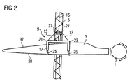
- Figure 2 shows the upper part of the wind turbine blade lifting system in a plan view onto the blade's body.
- the rotor hub 1 onto which the blade 3 is to be mounted It is located at a nacelle 33 at the top of a tower 35.
- the wind turbine blade lifting system comprises a crane boom 5 which is mounted onto a truck 7, a lifting device 9 which can be connected to the wind turbine blade 3, a winch arrangement comprising two individually controllable winches 11, control wires 13 (only one control wire is visible in Figure 1 ) and a bearing wire 15.
- the holding device 9 comprises a frame 17 and seats 19 on both ends 21, 23 of the frame 17 to which the wind turbine blade 3 is pressed by belts or straps 25.
- the bearing wire 15 is fixed to a central area of the frame 17 and the control wires 13 are fixed to the frame 17 at its ends 21, 23.
- the control wires run via pulleys 27 which are located at the boom 5 to the winches 11 of the winch arrangement. Both winches 11 of the winch arrangement are located at the bottom end 6 of the boom 5 and can be controlled individually so as to tension or loosen both control wires 13 individually.
- the pulleys 27 are mounted onto a sliding carriage 29 which can be moved along the boom 5.
- the bearing wire 15 is connected to a further winch 31 which is operated for lifting the lifting device 9 with the blade 3 fixed thereto.
- the control wires 13 have no substantial bearing function.
- the method comprises the steps of: i) lifting a wind turbine hub 1 to the nacelle 33 of a wind turbine with a lifting system and mounting the hub 1 on the nacelle 33, or lifting the wind turbine hub 1 and the nacelle 33 together with the lifting system and mounting the nacelle 33 including the hub 1 on a wind turbine tower 35; ii) lifting at least one wind turbine blade 3 with a lifting system for handling the wind turbine blades 3, lifting said at least one wind turbine blade 3 into a substantially horizontal position; iii) controlling the orientation of said at least one wind turbine blade 3 in the substantially horizontal position when it has been lifted off the ground, using control wires 13 connecting the lifting system to the crane boom 5, and iv) fixing said at least one wind turbine blade 3 in a substantially horizontal position to the wind turbine hub 1.
- a control wire 13 is attached at each end 21, 23 of the lifting frame 9, as has been described with respect to Figures 1 and 2 .
- the two control wires 13 run to the crane boom 5 and from there over a pulley 27 to two hydraulic winches 11 fitted to the crane boom 5 at its bottom end.
- the two hydraulic winches 11 can be controlled independently.
- the boom control wires 13 are kept automatically pre-tensioned during the lifting process so that control is maintained even though the distance from the pulleys 27 on the crane boom 5 to the lifting device 9 is changed during the hoisting of the lifting device 9. This is accomplished by having one hydraulic winch that automatically maintains wire tension and another hydraulic winch that regulates the horizontal orientation and is controlled manually.
- the wind turbine rotor hub 1 is mounted to the nacelle 33 of a wind turbine in a conventional manner by using the crane boom 5.
- the rotor hub 1 could be mounted to the nacelle 33 on the ground and the nacelle together with the rotor hub 1 mounted thereto would then be mounted to the top of the tower 35 by using the crane boom 5.
- As mounting the nacelle 33 onto the tower top and mounting the rotor hub 1 to the nacelle 33 are conventional steps they are not depicted in the figures.
- the lifting device 9 is mounted onto a wind turbine blade 3 which rests on the ground with its downstream edge 37 showing upwards.
- the frame 17 is lowered onto the rotor blade 3 so that the seats 19 are set onto the downstream section 37 of the blade 3.
- the belts 25 are wound around the upstream edge 39 of the blade 3, fixed to the frame 17 and tensioned so as to press the blade 3 to the seat 19.
- the lifting device 9 After the lifting device 9 has been mounted onto the blade 3 and the blade 3 has been secured to the lifting device 9 they are both lifted together by coiling the bearing wire 15 with the second winch 31. At the same time, the control wires 13 are tensioned so as to drag the lifting device 9 with the blade 3 mounted therein towards the crane boom 5. During lifting, the sliding carriage with the pulleys 27 follows the blade 3 on its way upwards where it is located slightly below the lifting device 9. By this measure the length of the control wires between the pulleys 27 and the frame 17 of the lifting device 9 can be kept low and almost constant during the whole lifting process.
- the tensioning force of the control wires act in a direction that includes an angle ⁇ to the lifting force exerted by the bearing wire 15.
- the angle ⁇ is about 120°. Therefore, the tensioning forces exerted by the control wires 13 have substantial components in the direction opposite the lifting force exerted by the bearing wire 15.
- the ratio of the tensioning force components which act in the opposite direction to the lifting force to those components which act perpendicular to the lifting force can be set by the position of the sliding carriage 29 relative to the lifting device 9. The lower the sliding carriage 29 is with respect to the lifting device 9 the higher the component of the tensioning force is that acts in the opposite direction to the lifting force as compared to the component acting in a perpendicular direction to the lifting force.
- the horizontal orientation of the turbine blade 3 can be varied. Varying the pre-tension of the control wires can either be done directly at the winches, for instance by personnel located at the winches 11, or remotely by the crane operator which would offer the advantage that all control actions for positioning the blade relative to the rotor hub 1 can be performed by the same person. Positioning the wind turbine blade 3 relative to the rotor hub 1 for mounting the blade 3 to the hub 1 is schematically shown in Figure 3 .
- pre-tensioning the control wires 13 and controlling the horizontal orientation of the wind turbine blade 3 is performed by controlling both winches 11 of the winch arrangement individually it would also be possible to provide a winch which is acting on both control wires so as to always exert the same tensioning force on both control wires 13 while a second winch is used for regulating the horizontal orientation of the wind turbine rotor blade 3.
- this simplification of controlling the horizontal position of the blade 3 has to be paid for by a more complex construction of the winch arrangement.
- the pulleys are mounted on a sliding carriage 29 which can move along the boom 5 the pulleys can also be located at the boom 5 at a fixed position.
- the ratio of the tensioning force components acting in the direction opposite the lifting force to the components acting perpendicular to the lifting force varies during the lifting process.
- this can be accounted for by suitably pre-tensioning the control wires 13 during the lifting process.
- FIG. 4 shows the embodiment in a perspective view similar to the view shown in figure 3 .
- Elements which do not differ from those in the lifting system described with respect to Figures 1 to 3 and which are not necessary for understanding the embodiment of the inventive wind turbine blade lifting system have been omitted from the figure for clarity reasons.
- Elements that have been omitted although present also in the embodiment of the inventive wind turbine blade lifting system are, for example, the seats 19 and the belts 25 of a lifting device 9.
- the embodiment of the inventive wind turbine blade lifting device differs from the lifting system described with respect to Figures 1 to 3 in that the control wire 113 is not directly connected to the crane boom 105 but is connected to the crane boom 105 indirectly via guiding ropes 121A, 121B. Therefore, the crane boom 105 of the second embodiment comprises a traverse beam 119 mounted to a top section of the crane boom 105 from which tensioned guiding ropes 121A, 121B extend to a winch arrangement (not shown) at the bottom end of the crane boom 105. The guiding ropes 121A, 121B are tensioned by this winch arrangement.
- a single control wire 113 is used for controlling the orientation of the lifting device 109 - and thereby the orientation of a blade mounted to the lifting device - within a horizontal plane.
- the control wire is subdivided into a first branch 113A and a second branch 113B where each branch comprises a section of the free length of the control wire 113.
- Both ends of the control wire 113 are connected to a spool of a winch 123, and both ends of the control wire can be wound up or off the spool of the winch so as to shorten or lengthen the free length of the control wire 113, respectively, by turning the spool.
- both ends are connected to a single winch 123 two individual winches, one for each end of the control wire 113 could be present as well.
- using a single winch has the advantage that the length of the control wire can be controlled by only controlling a single winch.
- An intermediate section of the control wire 113 is wound around the spool of a second winch 125.
- the intermediate section resembles a transition section between the first branch 113A and the second branch 113B.
- the configuration of the winch arrangement comprising the winches 123 and 125 as well as the arrangement of the control wire 113 is depicted schematically in figure 5 .
- the figure shows a top view onto the frame 117, the crane boom 105 and the traverse beam 119.
- the control wire 113 which is fixed with both of its ends to the spool of first winch 123, runs via two deflection pulleys 127 to a pulley arrangement comprising a first pulley 129A and a second pulley 131A (the whole pulley arrangement can be seen in figure 4 ) and from there back to a deflection pulley 127 and to the spool of the second winch 125.
- the control wire 113 is not fixed to the spool of second winch 125 but wrapped one or more times around it.
- the section of the control wire 113 that runs from the first winch 123 via the pulley arrangement 129A, 131A to the second winch 125 forms the first branch 113A of the control wire's free length.
- From the second winch 125 of the winch arrangement the control wire runs via a further deflection pulley to a pulley 129B of a pulley arrangement located between the control wire 113 and the second guiding rope 121B and from there via further deflection pulleys 127 back to the spool of the first winch 123 to which the second end of the control wire 113 is also fixed.
- winding the control wire ends up the spool of the first winch 123 will drag the frame 117, to which the winch arrangement is fixed, towards the crane boom 105.
- winding the ends of the control wire 113 off the winch 123 will allow the frame 117 to move away from the crane boom 105.
- rotating the spool of the second winch 125 will transfer free length from one of the branches 113A, 113B to the respective other branch. This leads to a shortening of one branch and, at the same time, to a lengthening of the respective other branch.
- the angle of the frame 117 within a horizontal plane, for example relative to the traverse 119 can be changed by controlling the second winch 125.
- both branches 113A, 113B of the control wire 113 are connected to a respective guiding rope 121A, 121b via pulley arrangements 129A, 131A, 129B, 131B.
- This pulley arrangements allows for lifting the connection point between the branches 113A, 113B and the respective guiding ropes 121A, 121B when the lifting device 109 (with a wind turbine rotor blade fixed thereto) is lifted by means of the bearing wire 115.
- the bearing wire comprises four branches each of which is connected to a corner of the frame 117.
- the bearing wire of the lifting system described with respect to Figures 1 to 3 could also be used in the embodiment of the inventive wind turbine blade lifting system and vice versa.
- the distance of the blade from the crane boom 105 as well as the orientation of the blade within the horizontal plane can be controlled independent of reach other by independently controlling the winches 123, 125 of the winch arrangement at the frame 117.
- the forces which are exerted by the winch arrangement and transferred to the pulley arrangements 129, 131 via the control wire 113 will be transferred by the pulley arrangements to the guiding ropes 121.
- By the guiding ropes 121A, 121B these forces will be transmitted to the crane boom at the locations at which the guiding ropes 121A, 121B are fixed to it.
- Lifting a wind turbine rotor blade with the embodiment of the inventive wind turbine blade lifting system does not differ from lifting a turbine blade with the lifting system described with respect to Figures 1 to 3 except for the way of controlling the orientation of the frame 117 and thereby the orientation of the blade within the horizontal plane and its distance from the crane boom.
- the invention provides a possibility of controlling a wind turbine rotor blade's orientation in the substantially horizontal position when it has been lifted off the ground, using control wires connecting the lifting system to a crane boom.
- the feature of lifting the wind turbine blade in the same substantially horizontal orientation as it has when fitted to the lifting device when lying on the ground is advantageous as this eliminates any need for upturning the blade.
- the feature of controlling the orientation of the blade in the substantially horizontal position when it has been lifted off the ground, using control wires connecting the lifting system to the crane boom is advantageous as it eliminates the need for a group of persons stationed at ground level and seeking to control the orientation using long ropes.
- the crane operator can control both the lifting height and the blade orientation from one control position.
Landscapes
- Engineering & Computer Science (AREA)
- Mechanical Engineering (AREA)
- Life Sciences & Earth Sciences (AREA)
- Sustainable Development (AREA)
- Sustainable Energy (AREA)
- Chemical & Material Sciences (AREA)
- Combustion & Propulsion (AREA)
- General Engineering & Computer Science (AREA)
- Wind Motors (AREA)
Claims (17)
- Procédé de montage d'une pale d'éolienne (3) sur un moyeu d'éolienne (1) au moyen d'une flèche de grue (5, 105), dans lequel l'orientation de la pale (3) est maintenue essentiellement horizontale lorsque la pale (3) est levée du sol et montée sur le moyeu de rotor (1),
caractérisé en ce qu'au moins un câble de commande (13, 113) et un système de treuil (11, 123, 125) sont utilisés pour commander l'orientation de la pale (3), en plus d'au moins un câble porteur (15, 115) pour supporter le poids de la pale. - Procédé selon la revendication 1,
caractérisé en ce que des câbles de commande (13) qui relient la pale (3) à un système de treuil (11) en passant par la flèche de grue (5) sont utilisés pour maintenir l'orientation de la pale (3) essentiellement horizontale et/ou pour commander l'orientation de la pale (3) dans un plan essentiellement horizontal, en plus du au moins un câble porteur (15) pour supporter le poids de la pale. - Procédé selon la revendication 2,
caractérisé en ce que le procédé comprend les étapes de :a) levage d'au moins une pale d'éolienne (3) à l'aide d'un système de levage destiné à la manutention des pales d'éolienne (3), dans lequel ladite au moins une pale d'éolienne (3) est orientée dans une position essentiellement horizontale, le système de levage utilisant un dispositif de levage (9) qui est conçu de manière à pouvoir être fixé sur la pale d'éolienne (3) et auquel les câbles de commande (13) et le au moins un câble porteur (15) sont reliés,b) commande de l'orientation de ladite au moins une pale d'éolienne (3) dans la position essentiellement horizontale, une fois qu'elle a été levée du sol, en utilisant les câbles de commande (13) etc) fixation de ladite au moins une pale d'éolienne (3) dans une position essentiellement horizontale sur le moyeu d'éolienne (1). - Procédé selon la revendication 3,
caractérisé en ce qu'il comprend, en outre, comme étape antérieure, l'étape de levage d'un moyeu d'éolienne (1) vers une nacelle (33) d'une éolienne à l'aide du système de levage et de montage du moyeu (1) sur la nacelle (33), ou de levage du moyeu d'éolienne (1) et de la nacelle (33) ensemble à l'aide du système de levage et de montage de la nacelle (33) incluant le moyeu (1) sur un mât d'éolienne (35). - Procédé selon l'une quelconque des revendications précédentes,
caractérisé en ce qu'au moins deux câbles de commande (13) sont utilisés, lesquels câbles peuvent être commandés indépendamment l'un de l'autre. - Procédé selon l'une quelconque des revendications précédentes,
caractérisé en ce que les câbles de commande (13) sont maintenus en prétension lorsque la pale (3) est levée. - Procédé selon la revendication 1,
caractérisé en ce qu'un système de treuil (123, 125) qui est situé au niveau d'un dispositif de levage (109) conçu de manière à pouvoir être fixé sur la pale d'éolienne (3) et au moins un câble de commande (113) qui peut être commandé par le système de treuil (123, 125) sont utilisés pour commander la distance de la pale (3) par rapport à la flèche de grue (105) et/ou l'orientation de la pale (3) dans un plan horizontal. - Procédé selon la revendication 7,
caractérisé en ce qu'un système de treuil (123, 125) comprenant au moins un premier treuil (123) et un second treuil (125) est utilisé pour commander le au moins un câble de commande (113), la distance de la pale (3) par rapport à la flèche de grue (105) étant commandée par le biais du premier treuil (123) et l'orientation de la pale (3) dans le plan horizontal étant commandée par le biais du second treuil (125). - Procédé selon la revendication 8,
caractérisé en ce que- un câble de commande (113) ayant une longueur libre avec au moins une première branche (113A) comprenant une première fraction du câble de commande (113) et une seconde branche (113B) comprenant une seconde fraction du câble de commande (113) est utilisé, les deux branches du câble de commande étant reliées directement ou indirectement à la flèche de grue (105),- la longueur libre du câble de commande (113) est commandée par le biais du premier treuil (123) et- la distribution de la longueur libre du câble de commande (113) entre la première fraction et la seconde fraction est commandée par le biais du second treuil (125). - Système de levage de pale d'éolienne comprenant un dispositif de levage (9, 109) avec un cadre (17, 117) qui est conçu de manière à pouvoir être relié à une pale d'éolienne (3), une flèche de grue (5, 105), un système de treuil (11, 123, 125) et au moins un câble de commande (13, 113) qui s'étend jusqu'au système de treuil (11, 123, 125) pour commander l'orientation de la pale afin qu'elle soit essentiellement horizontale et/ou pour commander l'orientation de la pale (3) dans un plan essentiellement horizontal une fois qu'elle a été levée du sol,
caractérisé en ce que le système de travail (123, 125) est situé au niveau du dispositif de levage (109). - Système de levage de pale d'éolienne selon la revendication 10,
dans lequel au moins un câble (121A, 121B) s'étend de l'extrémité supérieure de la flèche (105) à son extrémité inférieure et dans lequel le câble de commande (113) est relié au au moins un câble (121A, 121B). - Système de levage de pale d'éolienne selon la revendication 11,
dans lequel le au moins un câble de commande (113) est relié au au moins un câble (121A, 121B) au moyen de poulies (129A, 131A, 129B, 131B). - Système de levage de pale d'éolienne selon l'une quelconque des revendications 10 à 12,- qui comprend au moins un câble de commande (113) ayant une longueur libre avec au moins une première branche (113A) comprenant une première fraction du câble de commande (113) et une seconde branche (113B) comprenant une seconde fraction du câble de commande (113), les deux branches du câble de commande (113) étant reliées directement ou indirectement à la flèche de grue (105), et- dans lequel le système treuil (123, 125) comprend au moins un premier treuil (123) et un second treuil (125), le premier treuil (123) étant conçu pour agir sur le câble de commande (113) pour commander sa longueur libre et le second treuil (125) étant conçu pour agir sur le câble de commande (113) pour commander la distribution de la longueur libre du câble de commande (113) entre la première fraction et la seconde fraction.
- Système de levage de pale d'éolienne selon la revendication 13,
dans lequel le câble de commande (113) comprend des extrémités qui sont reliées au premier treuil (123) et une section intermédiaire qui est enroulée autour du second treuil (125). - Système de levage de pale d'éolienne selon la revendication 13 ou la revendication 14,
dans lequel un premier câble (121A) et un second câble (121B) s'étendent de l'extrémité supérieure de la flèche (105) à son extrémité inférieure et dans lequel la première branche (113A) et la seconde branche (113B) du câble de commande (113) sont reliées au premier câble (121A) et au second câble (121B), respectivement. - Système de levage de pale d'éolienne selon la revendication 15,
dans lequel la première branche (113A) et la seconde branche (113B) du câble de commande (113) sont reliées au premier câble (121A) et au second câble (121B), respectivement, au moyen de poulies (129A, 131A, 129B, 131B). - Système de levage de pale d'éolienne selon l'une quelconque des revendications 10 à 16,
dans lequel le au moins un câble de commande (113) s'étend essentiellement dans un plan horizontal.
Priority Applications (1)
| Application Number | Priority Date | Filing Date | Title |
|---|---|---|---|
| DK07856251.9T DK2084098T4 (da) | 2006-11-23 | 2007-11-23 | Fremgangsmåde og indretning til montering af vindmøllevinger. |
Applications Claiming Priority (5)
| Application Number | Priority Date | Filing Date | Title |
|---|---|---|---|
| EP06024337 | 2006-11-23 | ||
| EP06024336 | 2006-11-23 | ||
| EP07013725.2A EP1925583B2 (fr) | 2006-11-23 | 2007-07-12 | Procédé de manipulation de pales d'éoliennes et dispositif de montage de pales d'éoliennes, en particulier le montage de pales sur une éolienne |
| EP07013724A EP1925582B1 (fr) | 2006-11-23 | 2007-07-12 | Procédé et dispositif de montage de pales d'éoliennes |
| PCT/EP2007/010221 WO2008061797A1 (fr) | 2006-11-23 | 2007-11-23 | Procédé et dispositif de montage de pâles d'éolienne |
Publications (3)
| Publication Number | Publication Date |
|---|---|
| EP2084098A1 EP2084098A1 (fr) | 2009-08-05 |
| EP2084098B1 true EP2084098B1 (fr) | 2011-02-02 |
| EP2084098B2 EP2084098B2 (fr) | 2019-01-16 |
Family
ID=39315457
Family Applications (2)
| Application Number | Title | Priority Date | Filing Date |
|---|---|---|---|
| EP07013724A Active EP1925582B1 (fr) | 2006-11-23 | 2007-07-12 | Procédé et dispositif de montage de pales d'éoliennes |
| EP07856251.9A Active EP2084098B2 (fr) | 2006-11-23 | 2007-11-23 | Procédé et dispositif de montage de pales d éoliennes |
Family Applications Before (1)
| Application Number | Title | Priority Date | Filing Date |
|---|---|---|---|
| EP07013724A Active EP1925582B1 (fr) | 2006-11-23 | 2007-07-12 | Procédé et dispositif de montage de pales d'éoliennes |
Country Status (10)
| Country | Link |
|---|---|
| US (4) | US8191721B2 (fr) |
| EP (2) | EP1925582B1 (fr) |
| JP (1) | JP5420165B2 (fr) |
| CN (2) | CN101541660B (fr) |
| AT (1) | ATE497474T1 (fr) |
| CA (1) | CA2611343C (fr) |
| DE (1) | DE602007012362D1 (fr) |
| DK (1) | DK2084098T4 (fr) |
| ES (1) | ES2356024T5 (fr) |
| WO (1) | WO2008061797A1 (fr) |
Cited By (5)
| Publication number | Priority date | Publication date | Assignee | Title |
|---|---|---|---|---|
| US8191721B2 (en) | 2006-11-23 | 2012-06-05 | Siemens Aktiengesellschaft | Method and device for mounting of wind turbine blades |
| EP2589795A1 (fr) | 2011-11-04 | 2013-05-08 | Siemens Aktiengesellschaft | Cadre de levage pour lever une pale de rotor d'éolienne et procédé de montage de pales de rotor d'éolienne |
| US8710693B2 (en) | 2011-09-22 | 2014-04-29 | Mitsubishi Heavy Industries, Ltd. | Power generating apparatus of renewable energy type and method of attaching and detaching blade |
| US9840401B2 (en) | 2013-12-30 | 2017-12-12 | Siemens Aktiengesellschaft | Load guiding arrangement |
| US10294912B2 (en) | 2011-09-22 | 2019-05-21 | Mitsubishi Heavy Industries, Ltd. | Rotation blade attachment method for regeneration energy type electric generation apparatus |
Families Citing this family (152)
| Publication number | Priority date | Publication date | Assignee | Title |
|---|---|---|---|---|
| ES2339882T5 (es) * | 2006-11-23 | 2013-07-26 | Siemens Aktiengesellschaft | Procedimiento de manejo de palas de turbina eólica y dispositivo para el montaje de palas de turbina eólica, en particular el montaje de palas en una turbina eólica |
| JP4885071B2 (ja) * | 2007-06-19 | 2012-02-29 | 三菱重工業株式会社 | 風車用設備の交換方法 |
| JP4885073B2 (ja) * | 2007-06-20 | 2012-02-29 | 三菱重工業株式会社 | 風車回転翼の吊下げ装置、風車回転翼の取付け方法、および風力発電装置の建設方法 |
| WO2009100377A1 (fr) | 2008-02-07 | 2009-08-13 | Wind Innovatins Ip, Llc | Système de maintenance de moyeu de rotor |
| DE202008016578U1 (de) * | 2008-12-15 | 2011-04-07 | Liebherr-Werk Ehingen Gmbh | Manipulator zur Montage von Rotorblättern einer Windkraftanlage |
| EP2424811B8 (fr) * | 2009-04-29 | 2014-02-19 | Siemens Aktiengesellschaft | Système de levage de pale avec portes de type saloon |
| WO2010133228A2 (fr) * | 2009-05-18 | 2010-11-25 | Vestas Wind Systems A/S | Moyeu d'éolienne |
| FR2946700B1 (fr) | 2009-06-15 | 2018-07-20 | Soletanche Freyssinet | Procede, systeme et dispositif pour contribuer a l'assemblage d'une eolienne. |
| US20100143136A1 (en) * | 2009-08-31 | 2010-06-10 | Jeffrey Michael Daniels | Systems and methods for assembling a pitch assembly for use in a wind turbine |
| US8727690B2 (en) * | 2009-09-10 | 2014-05-20 | National Oilwell Varco, L.P. | Windmill handling system and method for using same |
| US8443571B2 (en) * | 2009-09-19 | 2013-05-21 | Btpatent Llc | Wind power equipment and assembly |
| US8070000B2 (en) * | 2009-10-23 | 2011-12-06 | Vestas Wind Systems A/S | Apparatus and method for assembling wind turbines |
| DE102009058268A1 (de) | 2009-12-14 | 2011-06-16 | Liebherr-Werk Ehingen Gmbh | Kran und Verfahren zum Anheben eines Rotors |
| DK2345811T3 (da) * | 2010-01-14 | 2012-11-19 | Siemens Ag | Klemme til klemning af et blad til en vindturbine og fremgangsmåde til installering af vindturbineblade |
| DK177006B1 (en) | 2010-01-19 | 2010-11-22 | Ah Ind Projects Aps | Method for controlling orientation of a load suspended in a carrier wire around the wire as well as a player arrangement |
| JP4547039B1 (ja) * | 2010-02-23 | 2010-09-22 | 株式会社日本製鋼所 | 風力発電用ローターブレードの取り付け方法 |
| DE202010012237U1 (de) * | 2010-09-06 | 2011-12-08 | Liebherr-Werk Ehingen Gmbh | Kran |
| DE202010015616U1 (de) * | 2010-11-18 | 2012-03-01 | Liebherr-Werk Ehingen Gmbh | Kran |
| EP2364948B1 (fr) * | 2010-03-08 | 2012-05-09 | Liebherr-Werk Ehingen GmbH | Grue |
| DE202010003269U1 (de) * | 2010-03-08 | 2011-08-23 | Liebherr-Werk Ehingen Gmbh | Kran |
| EP2369174B1 (fr) * | 2010-03-09 | 2012-11-28 | Lm Glasfiber A/S | Procédé pour le montage ou le démontage sans grue d'une pale d'éolienne |
| CN102192111B (zh) * | 2010-03-11 | 2012-11-07 | 中交上海三航科学研究院有限公司 | 海上风机叶片安装方法 |
| US20110221215A1 (en) * | 2010-03-12 | 2011-09-15 | Vestas Wind Systems A/S | Methods and apparatus for handling a tower section of a wind turbine with a crane |
| DE202010004093U1 (de) | 2010-03-23 | 2011-05-05 | Wobben, Aloys, Dipl.-Ing. | Hebeeinheit zum Heben eines Rotors einer Windenergieanlage |
| KR101285921B1 (ko) | 2010-05-31 | 2013-07-12 | 미츠비시 쥬고교 가부시키가이샤 | 풍차의 날개 선단부 보호 백 및 로터의 조립 방법 |
| CN101871425B (zh) * | 2010-06-22 | 2012-08-08 | 沈阳瑞祥风能设备有限公司 | 风力发电机叶片安装调整控制系统及控制方法 |
| ES1073014Y (es) | 2010-07-29 | 2011-03-01 | Acciona Windpower Sa | Uil para elevacion y descenso de una pala de aerogenerador |
| US9719487B2 (en) * | 2010-09-15 | 2017-08-01 | Vestas Wind Systems A/S | Wind turbine blade structures, lifting assemblies and methods of blade handling |
| DK2434142T3 (da) | 2010-09-27 | 2013-06-24 | Siemens Ag | Fremgangsmåde, enhed og system til montering af vindmøllevinger på et vindmøllenav |
| EP2532890A4 (fr) | 2011-04-05 | 2013-06-19 | Mitsubishi Heavy Ind Ltd | Dispositif generateur d'electricite a energie recuperee |
| US9261072B2 (en) * | 2011-05-11 | 2016-02-16 | Daniel E. Davis | Wind turbine elevator for hoisting a naecelle along a tower and pivoting the naecelle at a top of the tower |
| WO2012163358A1 (fr) | 2011-05-27 | 2012-12-06 | Vestas Wind Systems A/S | Appareil de manipulation d'une pale d'éolienne et procédé de manipulation de pale |
| DK2532879T3 (da) | 2011-06-07 | 2014-04-07 | Siemens Ag | Montering og/eller vedligeholdelse af en vindmølle |
| DE102011116189B3 (de) * | 2011-06-21 | 2012-10-04 | Repower Systems Se | Lasthandhabungsvorrichtung zum Anheben von Rotorblättern in eine Montageposition und Verfahren zur Montage von Rotorblättern an der Rotornabe einer Windenergieanlage |
| DK2538073T3 (en) | 2011-06-24 | 2016-07-25 | Vestas Wind Sys As | An improvement of a horizontal wing installation of windmills |
| US20120027611A1 (en) * | 2011-07-07 | 2012-02-02 | General Electric Company | Compression member for wind turbine rotor blades |
| KR20130050274A (ko) | 2011-08-10 | 2013-05-15 | 미츠비시 쥬고교 가부시키가이샤 | 재생 에너지형 발전 장치 |
| US8360398B2 (en) | 2011-08-17 | 2013-01-29 | General Electric Company | Device for handling a wind turbine rotor blade and a method for handling wind turbine rotor blades |
| US8595931B2 (en) | 2011-08-22 | 2013-12-03 | General Electric Company | Lift system and method for constructing a wind turbine |
| FR2979335B1 (fr) * | 2011-08-22 | 2015-11-13 | Degremont | Dispositif pour manipuler un objet allonge, en particulier un module de filtration membranaire, et procede de manipulation mettant en oeuvre ce dispositif |
| ES2399014B1 (es) * | 2011-09-07 | 2014-05-21 | Matis Hispania, S. A. | Herramienta para el izado de una pala de aerogenerador |
| DE102011121438A1 (de) * | 2011-12-16 | 2013-06-20 | Robert Bosch Gmbh | Vorrichtung zum Halten eines Bauteils |
| CN103174601B (zh) * | 2011-12-22 | 2015-05-27 | 华锐风电科技(集团)股份有限公司 | 风机叶片保护套 |
| DE102012201088A1 (de) * | 2012-01-25 | 2013-07-25 | Wobben Properties Gmbh | Verfahren und Vorrichtung zum Montieren einer Rotornabe einer Windenergieanlage |
| DK2623768T3 (da) * | 2012-02-03 | 2014-09-01 | Siemens Ag | Løfteramme til at løfte en vindmøllerotorvinge, fremgangsmåde til montering af en vindmøllerotorvinge til et vindmøllerotornav og fremgangsmåde til samling af en vindmøllerotor |
| CN103423105B (zh) * | 2012-05-21 | 2015-11-25 | 华锐风电科技(集团)股份有限公司 | 一种风电机组叶轮组装装置及叶轮组装方法 |
| EP2669238B1 (fr) | 2012-06-01 | 2016-12-14 | Siemens Aktiengesellschaft | Manipulation facilitée de pales d'éolienne |
| KR101346176B1 (ko) * | 2012-06-22 | 2013-12-31 | 삼성중공업 주식회사 | 풍력발전기용 블레이드의 조립로봇 |
| KR101346180B1 (ko) * | 2012-06-26 | 2013-12-31 | 삼성중공업 주식회사 | 풍력발전기용 블레이드 설치 시스템 |
| KR101323800B1 (ko) | 2012-06-28 | 2013-10-31 | 삼성중공업 주식회사 | 풍력발전기용 블레이드의 조립로봇 |
| GB201214656D0 (en) * | 2012-08-16 | 2012-10-03 | W3G Shipping Ltd | Offshore structures and associated apparatus and method |
| EP2890626B1 (fr) | 2012-08-30 | 2019-06-26 | High Wind N.V. | Dispositif et procédé pour assembler une structure |
| US9950910B2 (en) | 2012-09-11 | 2018-04-24 | Eltronic A/S | Method for controlling the orientation of a load suspended from a bearing wire about said bearing wire and a winch arrangement |
| EP2708734B1 (fr) * | 2012-09-13 | 2016-11-09 | ALSTOM Renewable Technologies | Pale d'éolienne et procédés de transport, de stockage et d'installation desdites pales |
| CN102852722B (zh) * | 2012-09-27 | 2014-09-17 | 北京金风科创风电设备有限公司 | 用于直驱风力发电机组中叶轮的轮毂变位装置及吊装方法 |
| KR101401985B1 (ko) * | 2012-09-28 | 2014-05-30 | (주)살코 | 수상구조물 설치용 잭업식 플로팅 크레인 |
| DE102012109403B3 (de) * | 2012-10-02 | 2014-03-06 | Repower Systems Se | Verfahren zur Montage eines Rotorblattes und Montageanordnung |
| DK177672B1 (da) * | 2012-11-27 | 2014-02-17 | Liftra Ip Aps | Løfteramme |
| WO2014097254A1 (fr) * | 2012-12-20 | 2014-06-26 | High Wind N.V. | Dispositif et procédé de mise en place d'un élément structural |
| BE1021593B1 (nl) * | 2012-12-20 | 2015-12-16 | High Wind Nv | Inrichting en werkwijze voor het ter zee plaatsen van een bouwwerkonderdeel |
| KR102151476B1 (ko) * | 2012-12-20 | 2020-09-04 | 하이 윈드 엔.브이. | 구조물의 요소를 배치하기 위한 장치 및 방법 |
| KR101400203B1 (ko) * | 2013-01-29 | 2014-05-27 | 삼성중공업 주식회사 | 밸런싱 장치 및 이를 이용한 풍력 발전기용 블레이드 장착 방법 |
| BE1021796B1 (nl) * | 2013-02-18 | 2016-01-18 | High Wind N.V. | Inrichting en werkwijze voor het op zee plaatsen van een rotorblad van een windturbine |
| WO2014125461A1 (fr) * | 2013-02-18 | 2014-08-21 | High Wind N.V. | Dispositif et procédé permettant de placer une pale de rotor d'une éolienne |
| US9321616B2 (en) * | 2013-03-14 | 2016-04-26 | Marvin M. May | Lifting systems |
| US9145867B2 (en) * | 2013-03-14 | 2015-09-29 | General Electric Company | System and method for installing a blade insert between separate portions of a wind turbine rotor blade |
| DE102013205030B4 (de) * | 2013-03-21 | 2015-10-22 | Senvion Gmbh | System und Verfahren zum Transportieren und Prüfen eines zur Verwendung bei einer Offshore-Windenergieanlage bestimmten Krans |
| KR101484121B1 (ko) * | 2013-03-29 | 2015-01-21 | 곽대진 | 풍력타워 설치용 해상 크레인 |
| CN103277269A (zh) * | 2013-05-17 | 2013-09-04 | 江苏金风科技有限公司 | 用于风力发电机组叶片旋转的方法和设备 |
| DE102013211751A1 (de) * | 2013-06-21 | 2014-12-24 | Wobben Properties Gmbh | Verfahren zum Montieren eines Windenergieanlagen-Rotorblattes sowie Windenergieanlagen-Rotorblatt |
| DE102014207712A1 (de) * | 2013-06-24 | 2014-12-24 | Siemens Aktiengesellschaft | Vorrichtung und Verfahren zum Drehen eines Rotors einer Windkraftanlage |
| DE102014003906A1 (de) * | 2013-07-01 | 2015-01-08 | Liebherr-Werk Biberach Gmbh | Turmdrehkran |
| DE202013006584U1 (de) * | 2013-07-22 | 2014-10-23 | Liebherr-Werk Ehingen Gmbh | Ballastvorrichtung zur Erzeugung einer Windenvorspannung |
| DK2832677T3 (en) * | 2013-07-29 | 2016-08-22 | Siemens Ag | Tool and device for gripping wings |
| US20150028608A1 (en) * | 2013-07-29 | 2015-01-29 | General Electric Company | Method and apparatus for handling a rotor blade |
| EP2832675B1 (fr) * | 2013-07-29 | 2018-07-04 | Siemens Aktiengesellschaft | Dispositif de préhension de pale |
| US9429138B2 (en) * | 2013-08-09 | 2016-08-30 | Gamesa Innovation & Technology, S.L. | Apparatus, system and method for wind turbine component replacement |
| EP2837819B1 (fr) * | 2013-08-14 | 2016-03-23 | Siemens Aktiengesellschaft | Procédé pour installer une pale de rotor |
| DE102013110464A1 (de) * | 2013-09-23 | 2015-03-26 | Max Bögl Wind AG | Vorrichtung und Verfahren zur Handhabung, Montage oder Demontage von Komponenten einer Windkraftanlage |
| BE1021044B1 (fr) * | 2013-11-06 | 2015-02-25 | Dufour Sa | Dispositif et methode pour mettre en tension le cable de levage d'une grue via son crochet en enroulant le cable sur le treuil de levage de la grue |
| WO2015084173A1 (fr) | 2013-12-05 | 2015-06-11 | Xemc Darwind B.V. | Procédé de manipulation d'une pale d'éolienne à entraînement direct ; et ensemble éolienne à entraînement direct |
| EP2924278B1 (fr) | 2014-03-26 | 2018-08-08 | Areva Wind GmbH | Outil permettant de manipuler un objet lourd et long |
| US10611608B2 (en) | 2014-04-28 | 2020-04-07 | Liftra Ip Aps | Method and device for automatic control of the position of a burden suspended in a main wire on a crane |
| DK178141B1 (en) * | 2014-06-03 | 2015-06-22 | Envision Energy | Wind turbine blade lifting device and a method for lifting a wind turbine blade |
| DE102015006992B4 (de) * | 2014-06-10 | 2021-04-15 | Liebherr-Werk Ehingen Gmbh | Verfahren und System zur Berechnung von Daten für den Betrieb eines Krans |
| DK178406B1 (en) * | 2014-06-12 | 2016-02-08 | Envision Energy Denmark Aps | Lifting device for rotor assembly and method thereof |
| US9651021B2 (en) | 2014-09-09 | 2017-05-16 | General Electric Company | System and method for removing and/or installing a rotor blade of a wind turbine |
| PT3020622T (pt) * | 2014-11-11 | 2017-09-11 | Seasight Davits Aps | Sistema e unidade de elevação para elevar cargas de peso variante |
| KR101657224B1 (ko) * | 2015-02-09 | 2016-09-13 | 박병룡 | 풍력타워 설치용 해상 크레인 |
| US10214392B2 (en) * | 2015-03-18 | 2019-02-26 | Siemens Aktiengesellschaft | Automated receptor system |
| EP3070044B1 (fr) * | 2015-03-19 | 2018-08-08 | ALSTOM Renewable Technologies | Systèmes et procédés de levage |
| US9650840B2 (en) | 2015-04-27 | 2017-05-16 | National Oilwell Varco, L.P. | Method and apparatus for erecting a drilling rig |
| US9821417B2 (en) | 2015-05-07 | 2017-11-21 | General Electric Company | System and method for replacing a pitch bearing |
| US9890022B2 (en) | 2015-05-07 | 2018-02-13 | General Electric Company | Method for suspending a rotor blade from a hub of a wind turbine |
| DE102015006778A1 (de) | 2015-06-01 | 2016-12-01 | Senvion Gmbh | System und Verfahren zum Transportieren und Heben eines Rotorblatts einer Windenergieanlage |
| US10287940B2 (en) | 2015-08-06 | 2019-05-14 | Clean Air-Engineering—Maritime, Inc. | Movable emission control system for auxiliary diesel engines |
| US10422260B2 (en) * | 2015-08-06 | 2019-09-24 | Clean Air-Engineering-Maritime, Inc. | Movable emission control system for auxiliary diesel engines |
| DE102015115146A1 (de) * | 2015-09-09 | 2017-03-09 | Bauer Maschinen Gmbh | Baumaschine und Verfahren zum Auf- und Abbewegen eines Hubelementes |
| WO2017054830A1 (fr) * | 2015-10-01 | 2017-04-06 | Vestas Wind Systems A/S | Agencement de levage permettant de soulever un composant de turbine d'éolienne |
| JP6769700B2 (ja) * | 2015-10-19 | 2020-10-14 | 三菱航空機株式会社 | 航空機の降着装置ハンドリング用ドーリーと、それを用いる降着装置の取り付け方法および取り外し方法 |
| US10066601B2 (en) | 2015-10-22 | 2018-09-04 | General Electric Company | System and method for manufacturing wind turbine rotor blades for simplified installation and removal |
| WO2017108052A1 (fr) * | 2015-12-22 | 2017-06-29 | Vestas Wind Systems A/S | Procédé et système de montage d'un rotor sur un arbre d'entraînement d'une éolienne |
| GB201603545D0 (en) * | 2016-03-01 | 2016-04-13 | Vestas Wind Sys As | Method and apparatus for weighing an elongate object |
| CN105692448B (zh) * | 2016-04-12 | 2018-07-20 | 南通润邦重机有限公司 | 一种角度可调式起重机稳货系统 |
| WO2017217845A1 (fr) * | 2016-06-15 | 2017-12-21 | Itrec B.V. | Grue pour ensemble pale d'éolienne, navire, procédé de hissage et procédé d'assemblage |
| DE102016111514A1 (de) * | 2016-06-23 | 2017-12-28 | Wobben Properties Gmbh | Verfahren zum Errichten einer Windenergieanlage und Hebetraverse zur Montage eines Rotorblatts einer Windenergieanlage |
| CN105947890B8 (zh) * | 2016-06-24 | 2017-12-22 | 成都世唯科技有限公司 | 一种风力发电机用叶吊具的偏摆机构 |
| CN109996750B (zh) * | 2016-10-20 | 2021-10-29 | 西门子歌美飒可再生能源公司 | 用于风力涡轮机部件的提升装置和方法 |
| CN106315408B (zh) * | 2016-10-21 | 2017-11-28 | 成都世唯科技有限公司 | 一种风叶装拆空中姿态调整设备 |
| EP3507230B1 (fr) * | 2016-11-03 | 2023-07-05 | Siemens Gamesa Renewable Energy A/S | Dispositif de levage pour composants d'éolienne |
| US11499527B2 (en) | 2016-12-21 | 2022-11-15 | Vestas Wind Systems A/S | Wind turbine service or construction method and apparatus |
| CN110088459A (zh) | 2016-12-23 | 2019-08-02 | 维斯塔斯风力系统有限公司 | 一种用于处理风轮机叶片的方法和组件 |
| CN110100090B (zh) | 2016-12-23 | 2021-07-06 | 维斯塔斯风力系统有限公司 | 一种处理风轮机叶片的方法和组件 |
| DK3563056T3 (da) * | 2016-12-28 | 2022-03-07 | Vestas Wind Sys As | Fremgangsmåde og system til at løfte en vindmøllerotor |
| DE202017100494U1 (de) * | 2017-01-30 | 2018-05-03 | Ematec Manfred Eberhard Maschinen- Und Greiftechnik E.K. | Vorrichtung zum kontrollierten Bewegen einer Last und Krananordnung |
| CN113446172A (zh) * | 2017-02-27 | 2021-09-28 | 莱博机器人株式会社 | 用于进行物体维护的装置、系统 |
| CN106865415A (zh) * | 2017-03-30 | 2017-06-20 | 中国矿业大学 | 一种抑止重物摆动和转动的大型通用吊装稳定装置及方法 |
| DE102017206349B4 (de) * | 2017-04-12 | 2019-04-11 | Siemens Gamesa Renewable Energy A/S | Wiegevorrichtung für ein Windenergieanlagen-Rotorblatt |
| ES2870228T3 (es) | 2017-04-18 | 2021-10-26 | Siemens Gamesa Renewable Energy As | Procedimiento para instalar o desinstalar un componente de una turbina eólica |
| CN107178456B (zh) * | 2017-05-16 | 2019-05-17 | 哈尔滨工程大学 | 一种水平轴潮流发电装置叶片海上安装方法 |
| US11198597B2 (en) * | 2017-06-12 | 2021-12-14 | Siemens Gamesa Renewable Energy A/S | Sensing arrangement for stabilizing an offshore wind turbine installation arrangement |
| IT201700068019A1 (it) | 2017-06-19 | 2018-12-19 | Saipem Spa | Telaio stabilizzatore, sistema e metodo per l'installazione di un generatore eolico su una struttura di sostegno offshore |
| US10508645B2 (en) | 2017-07-17 | 2019-12-17 | General Electric Company | System and method for suspending a rotor blade of a wind turbine uptower |
| ES2937912T3 (es) | 2017-12-13 | 2023-04-03 | Enabl As | Sistema, dispositivo y método para levantar y controlar la orientación y/o posición horizontal de componentes |
| NL2020389B1 (en) | 2018-02-06 | 2019-08-14 | Itrec Bv | A crane |
| MX2020011337A (es) * | 2018-04-30 | 2021-01-08 | Gen Electric | Metodos de fabricacion de turbinas eolicas, aspas del rotor y sus componentes. |
| EP4276305A3 (fr) | 2018-05-17 | 2024-01-17 | Vestas Wind Systems A/S | Procédé et appareil de levage d'élément de turbine éolienne |
| JP7151236B2 (ja) * | 2018-07-20 | 2022-10-12 | 株式会社大林組 | ブレード取り付け装置 |
| EP3830411B1 (fr) * | 2018-07-27 | 2023-03-15 | Vestas Wind Systems A/S | Procédé d'installation d'un rotor sur une éolienne, ensemble moyeu de rotor et contrepoids |
| DK180504B1 (en) * | 2018-09-13 | 2021-06-03 | Liftra Ip Aps | Rotor blade hoisting system and method for mounting and / or removing a rotor blade |
| US11905143B2 (en) | 2018-12-28 | 2024-02-20 | Vestas Wind Systems A/S | Method for handling a wind turbine component with a control arrangement |
| EP3902763A1 (fr) * | 2018-12-28 | 2021-11-03 | Vestas Wind Systems A/S | Ensemble de levage et procédé de manipulation d'un élément |
| JP7238531B2 (ja) * | 2019-03-26 | 2023-03-14 | 株式会社タダノ | クレーン |
| DK180819B1 (en) * | 2019-04-02 | 2022-04-28 | Liftra Ip Aps | Method for mounting a self-lifting crane on a wind turbine and self-lifting crane |
| DK180872B1 (en) * | 2019-05-02 | 2022-06-08 | Liftra Ip Aps | Self-hoisting crane system and method for hoisting a self-hoisting crane |
| US20220220942A1 (en) * | 2019-06-11 | 2022-07-14 | Vestas Wind Systems A/S | Method for handling a wind turbine component and associated lifting system |
| CN110329939B (zh) * | 2019-07-19 | 2021-01-26 | 燕山大学 | 一种叶轮吊装辅助对接装置 |
| DK180448B1 (en) | 2019-09-11 | 2021-04-28 | Eltronic As | A load guiding arrangement arranged for mounting to a crane |
| CN110654987B (zh) * | 2019-09-29 | 2020-07-24 | 大连理工大学 | 实现双向合力控制的吊机延伸加装装置及双向张力控制吊车的方法 |
| CN111170174B (zh) * | 2019-12-12 | 2021-06-08 | 江苏鹤钢重工有限公司 | 一种风力发电叶片用起重运输设备 |
| BE1028262B1 (nl) | 2020-05-04 | 2021-12-07 | Deme Offshore Be Nv | Hefsysteem en werkwijze voor het opnemen van een langwerpig object |
| CN111943060B (zh) * | 2020-08-17 | 2022-03-18 | 交通运输部公路科学研究所 | 姿态调整方法 |
| EP3957593A1 (fr) * | 2020-08-19 | 2022-02-23 | Siemens Gamesa Renewable Energy A/S | Appareil de levage pour une grue de levage |
| CN112027909A (zh) * | 2020-08-25 | 2020-12-04 | 广东工业大学 | 一种海上巨型叶片防转动和摆动的吊装控制方法及其装置 |
| CN112174013B (zh) * | 2020-09-28 | 2022-03-01 | 中天科技集团海洋工程有限公司 | 一种叶轮用的搬运装置及其搬运方法 |
| EP4027007A1 (fr) * | 2021-01-12 | 2022-07-13 | General Electric Renovables España S.L. | Procédé de montage de pales sur un moyeu de rotor d'une éolienne |
| CN114248875B (zh) * | 2022-01-07 | 2022-12-06 | 烟台大学 | 海洋科考设备止荡回收装置 |
| JP7480817B2 (ja) | 2022-10-14 | 2024-05-10 | 株式会社大林組 | 回転体設置方法およびブレードリフトアップ装置 |
| WO2024083833A1 (fr) | 2022-10-19 | 2024-04-25 | Itrec B.V. | Grue ayant une flèche de grue pourvue d'un système de câble stabilisateur |
| CN115366046B (zh) * | 2022-10-27 | 2023-01-31 | 新乡西玛鼓风机股份有限公司 | 一种用于锅炉风机叶轮的拆轴装置 |
| CN116281603B (zh) * | 2023-05-16 | 2023-07-21 | 河北倚天建筑科技有限公司 | 一种预制结构安装用墙板吊装装置 |
| CN117142353B (zh) * | 2023-10-31 | 2024-01-09 | 大连华锐重工集团股份有限公司 | 核岛主设备全自动翻转控制方法 |
Family Cites Families (25)
| Publication number | Priority date | Publication date | Assignee | Title |
|---|---|---|---|---|
| US2166479A (en) * | 1938-04-23 | 1939-07-18 | Marion P Mccaffrey | Tag-line device |
| GB1031022A (en) | 1964-01-22 | 1966-05-25 | Vickers Ltd | Restraining crane loads from swinging |
| US3545629A (en) | 1968-10-18 | 1970-12-08 | Owatonna Tool Co | Load handling device |
| US3658191A (en) * | 1970-12-14 | 1972-04-25 | Thomas V Murphy | Crane for extracting horizontally-aligned relatively-long tube bundles |
| GB1439411A (en) | 1973-03-21 | 1976-06-16 | Stothert & Pitt Ltd | Single point supsension attachment for load handling spreader frames |
| EP0037950A1 (fr) | 1980-04-10 | 1981-10-21 | Agfa-Gevaert AG | Procédé et appareil pour maintenir automatiquement une pression constante |
| DE4000095A1 (de) | 1990-01-03 | 1991-07-04 | Liebherr Werk Nenzing | Kran |
| EP0471305A1 (fr) | 1990-08-17 | 1992-02-19 | Paul Frey-Wigger | Plate-forme attachable à une grue mobile |
| JPH04237876A (ja) * | 1991-01-22 | 1992-08-26 | Mitsubishi Heavy Ind Ltd | 風車の耐風装置 |
| GB2252295B (en) | 1991-01-31 | 1994-08-03 | James Daniel Davidson | Offshore crane control system |
| JPH05227062A (ja) | 1991-10-25 | 1993-09-03 | Nec Corp | 回線品質チェック方法 |
| JPH0680380A (ja) | 1992-09-07 | 1994-03-22 | Kajima Corp | クレーン吊荷の水平姿勢保持装置 |
| JP2507856B2 (ja) | 1992-11-20 | 1996-06-19 | 鹿島建設株式会社 | 吊荷旋回制御方法 |
| JP2737048B2 (ja) | 1994-05-31 | 1998-04-08 | 小松メック株式会社 | 移動式クレーン |
| JPH10129980A (ja) | 1996-10-29 | 1998-05-19 | Hitachi Constr Mach Co Ltd | 油圧タグライン装置を有するクレーン |
| US5893471A (en) * | 1997-06-05 | 1999-04-13 | Zakula; Daniel Brian | Freely-movable auxiliary hoist for a gantry crane and method for pivoting a load |
| JP2000204792A (ja) | 1999-01-12 | 2000-07-25 | Mitsubishi Heavy Ind Ltd | 塔状建築物の組立及び/又はメインテナンス用架構、及び、かかる塔状建築物の組立及び/又はメインテナンス方法 |
| DE20109835U1 (de) | 2001-06-15 | 2002-01-24 | Gerken Gmbh | Arbeitsbühne |
| DE60209494T2 (de) | 2002-05-27 | 2006-08-24 | Vestas Wind Systems A/S | Verfahren zur handhabung von windturbinenschaufeln und zur anbringung der genannten schaufeln an einer windturbine, system und greifeinheit zur handhabung einer windturbinenschaufel |
| DK1518053T3 (da) | 2002-05-28 | 2010-01-25 | Iti Scotland Ltd | Fremgangsmåde og kran til installering, vedligehold og demontering af vindturbiner |
| DE10305543C5 (de) * | 2003-02-10 | 2011-04-28 | Aloys Wobben | Verfahren zur Montage von Rotorblättern sowie ein Rotorblatt für eine Windenergieanlage |
| US7114924B2 (en) * | 2004-03-10 | 2006-10-03 | Donald Terryl Munsch | Blade pin alignment and positioning system for installation of helicopter rotor blades |
| US20060045653A1 (en) * | 2004-07-16 | 2006-03-02 | Guidry Mark L | Pick-up and lay-down system and method |
| DK200501312A (da) * | 2005-09-21 | 2007-03-22 | Lm Glasfiber As | Fastgörelsesanordninger på vinge |
| EP1925582B1 (fr) * | 2006-11-23 | 2010-06-23 | Siemens Aktiengesellschaft | Procédé et dispositif de montage de pales d'éoliennes |
-
2007
- 2007-07-12 EP EP07013724A patent/EP1925582B1/fr active Active
- 2007-11-19 US US11/986,035 patent/US8191721B2/en active Active
- 2007-11-20 JP JP2007300140A patent/JP5420165B2/ja active Active
- 2007-11-21 CA CA2611343A patent/CA2611343C/fr active Active
- 2007-11-23 DK DK07856251.9T patent/DK2084098T4/da active
- 2007-11-23 AT AT07856251T patent/ATE497474T1/de not_active IP Right Cessation
- 2007-11-23 WO PCT/EP2007/010221 patent/WO2008061797A1/fr active Application Filing
- 2007-11-23 EP EP07856251.9A patent/EP2084098B2/fr active Active
- 2007-11-23 ES ES07856251T patent/ES2356024T5/es active Active
- 2007-11-23 CN CN2007800434988A patent/CN101541660B/zh active Active
- 2007-11-23 US US12/515,805 patent/US8601688B2/en active Active
- 2007-11-23 CN CN2007101936269A patent/CN101230835B/zh active Active
- 2007-11-23 DE DE602007012362T patent/DE602007012362D1/de active Active
-
2012
- 2012-04-06 US US13/441,178 patent/US8966753B2/en active Active
-
2013
- 2013-09-30 US US14/041,556 patent/US9009964B2/en active Active
Cited By (6)
| Publication number | Priority date | Publication date | Assignee | Title |
|---|---|---|---|---|
| US8191721B2 (en) | 2006-11-23 | 2012-06-05 | Siemens Aktiengesellschaft | Method and device for mounting of wind turbine blades |
| US8966753B2 (en) | 2006-11-23 | 2015-03-03 | Siemens Aktiengesellschaft | Method for mounting wind turbine blades to a wind turbine hub |
| US8710693B2 (en) | 2011-09-22 | 2014-04-29 | Mitsubishi Heavy Industries, Ltd. | Power generating apparatus of renewable energy type and method of attaching and detaching blade |
| US10294912B2 (en) | 2011-09-22 | 2019-05-21 | Mitsubishi Heavy Industries, Ltd. | Rotation blade attachment method for regeneration energy type electric generation apparatus |
| EP2589795A1 (fr) | 2011-11-04 | 2013-05-08 | Siemens Aktiengesellschaft | Cadre de levage pour lever une pale de rotor d'éolienne et procédé de montage de pales de rotor d'éolienne |
| US9840401B2 (en) | 2013-12-30 | 2017-12-12 | Siemens Aktiengesellschaft | Load guiding arrangement |
Also Published As
| Publication number | Publication date |
|---|---|
| DE602007012362D1 (de) | 2011-03-17 |
| CN101230835B (zh) | 2012-11-14 |
| DK2084098T3 (da) | 2011-03-28 |
| WO2008061797A1 (fr) | 2008-05-29 |
| ES2356024T5 (es) | 2020-03-24 |
| US20120192402A1 (en) | 2012-08-02 |
| ATE497474T1 (de) | 2011-02-15 |
| CA2611343C (fr) | 2015-02-03 |
| CN101230835A (zh) | 2008-07-30 |
| US9009964B2 (en) | 2015-04-21 |
| CA2611343A1 (fr) | 2008-05-23 |
| EP1925582A1 (fr) | 2008-05-28 |
| CN101541660A (zh) | 2009-09-23 |
| US8601688B2 (en) | 2013-12-10 |
| EP1925582B1 (fr) | 2010-06-23 |
| US20080216301A1 (en) | 2008-09-11 |
| DK2084098T4 (da) | 2020-04-20 |
| JP2008128252A (ja) | 2008-06-05 |
| EP2084098A1 (fr) | 2009-08-05 |
| US8191721B2 (en) | 2012-06-05 |
| CN101541660B (zh) | 2013-10-30 |
| US8966753B2 (en) | 2015-03-03 |
| JP5420165B2 (ja) | 2014-02-19 |
| US20100018055A1 (en) | 2010-01-28 |
| EP2084098B2 (fr) | 2019-01-16 |
| ES2356024T3 (es) | 2011-04-04 |
| US20140027400A1 (en) | 2014-01-30 |
Similar Documents
| Publication | Publication Date | Title |
|---|---|---|
| EP2084098B1 (fr) | Procédé et dispositif de montage de pâles d'éolienne | |
| CN111918832B (zh) | 起重机和用于定位物体的方法 | |
| JP6002248B2 (ja) | 重量昇降装置及び方法 | |
| EP2490975B1 (fr) | Appareil et procédé améliorés pour l'assemblage d'éoliennes | |
| US20180022583A1 (en) | Load guiding arrangement | |
| WO2011110254A2 (fr) | Procédé de montage ou de démontage sans grue d'une pale d'éolienne | |
| JP2008128252A6 (ja) | 風力タービンブレードの取り付け方法及び装置 | |
| US20220235739A1 (en) | Wind turbine tower with crane connection elements and a crane with tower flange connection elements | |
| EP3902763A1 (fr) | Ensemble de levage et procédé de manipulation d'un élément | |
| CN113454017B (zh) | 用控制装置处理风力涡轮机部件的方法 |
Legal Events
| Date | Code | Title | Description |
|---|---|---|---|
| PUAI | Public reference made under article 153(3) epc to a published international application that has entered the european phase |
Free format text: ORIGINAL CODE: 0009012 |
|
| 17P | Request for examination filed |
Effective date: 20090318 |
|
| AK | Designated contracting states |
Kind code of ref document: A1 Designated state(s): AT BE BG CH CY CZ DE DK EE ES FI FR GB GR HU IE IS IT LI LT LU LV MC MT NL PL PT RO SE SI SK TR |
|
| RIN1 | Information on inventor provided before grant (corrected) |
Inventor name: MOELLER, JESPER Inventor name: LYNDERUP, HENRIK, FOMSGAARD |
|
| DAX | Request for extension of the european patent (deleted) | ||
| GRAP | Despatch of communication of intention to grant a patent |
Free format text: ORIGINAL CODE: EPIDOSNIGR1 |
|
| GRAS | Grant fee paid |
Free format text: ORIGINAL CODE: EPIDOSNIGR3 |
|
| GRAA | (expected) grant |
Free format text: ORIGINAL CODE: 0009210 |
|
| AK | Designated contracting states |
Kind code of ref document: B1 Designated state(s): AT BE BG CH CY CZ DE DK EE ES FI FR GB GR HU IE IS IT LI LT LU LV MC MT NL PL PT RO SE SI SK TR |
|
| REG | Reference to a national code |
Ref country code: GB Ref legal event code: FG4D |
|
| REG | Reference to a national code |
Ref country code: CH Ref legal event code: EP |
|
| REG | Reference to a national code |
Ref country code: IE Ref legal event code: FG4D |
|
| REF | Corresponds to: |
Ref document number: 602007012362 Country of ref document: DE Date of ref document: 20110317 Kind code of ref document: P |
|
| REG | Reference to a national code |
Ref country code: DE Ref legal event code: R096 Ref document number: 602007012362 Country of ref document: DE Effective date: 20110317 |
|
| REG | Reference to a national code |
Ref country code: DK Ref legal event code: T3 |
|
| REG | Reference to a national code |
Ref country code: ES Ref legal event code: FG2A Ref document number: 2356024 Country of ref document: ES Kind code of ref document: T3 Effective date: 20110404 |
|
| REG | Reference to a national code |
Ref country code: SE Ref legal event code: TRGR |
|
| REG | Reference to a national code |
Ref country code: NL Ref legal event code: VDEP Effective date: 20110202 |
|
| LTIE | Lt: invalidation of european patent or patent extension |
Effective date: 20110202 |
|
| PG25 | Lapsed in a contracting state [announced via postgrant information from national office to epo] |
Ref country code: LV Free format text: LAPSE BECAUSE OF FAILURE TO SUBMIT A TRANSLATION OF THE DESCRIPTION OR TO PAY THE FEE WITHIN THE PRESCRIBED TIME-LIMIT Effective date: 20110202 Ref country code: PT Free format text: LAPSE BECAUSE OF FAILURE TO SUBMIT A TRANSLATION OF THE DESCRIPTION OR TO PAY THE FEE WITHIN THE PRESCRIBED TIME-LIMIT Effective date: 20110602 Ref country code: GR Free format text: LAPSE BECAUSE OF FAILURE TO SUBMIT A TRANSLATION OF THE DESCRIPTION OR TO PAY THE FEE WITHIN THE PRESCRIBED TIME-LIMIT Effective date: 20110503 Ref country code: LT Free format text: LAPSE BECAUSE OF FAILURE TO SUBMIT A TRANSLATION OF THE DESCRIPTION OR TO PAY THE FEE WITHIN THE PRESCRIBED TIME-LIMIT Effective date: 20110202 Ref country code: IS Free format text: LAPSE BECAUSE OF FAILURE TO SUBMIT A TRANSLATION OF THE DESCRIPTION OR TO PAY THE FEE WITHIN THE PRESCRIBED TIME-LIMIT Effective date: 20110602 |
|
| PG25 | Lapsed in a contracting state [announced via postgrant information from national office to epo] |
Ref country code: BG Free format text: LAPSE BECAUSE OF FAILURE TO SUBMIT A TRANSLATION OF THE DESCRIPTION OR TO PAY THE FEE WITHIN THE PRESCRIBED TIME-LIMIT Effective date: 20110502 Ref country code: CY Free format text: LAPSE BECAUSE OF FAILURE TO SUBMIT A TRANSLATION OF THE DESCRIPTION OR TO PAY THE FEE WITHIN THE PRESCRIBED TIME-LIMIT Effective date: 20110202 Ref country code: AT Free format text: LAPSE BECAUSE OF FAILURE TO SUBMIT A TRANSLATION OF THE DESCRIPTION OR TO PAY THE FEE WITHIN THE PRESCRIBED TIME-LIMIT Effective date: 20110202 Ref country code: SI Free format text: LAPSE BECAUSE OF FAILURE TO SUBMIT A TRANSLATION OF THE DESCRIPTION OR TO PAY THE FEE WITHIN THE PRESCRIBED TIME-LIMIT Effective date: 20110202 Ref country code: NL Free format text: LAPSE BECAUSE OF FAILURE TO SUBMIT A TRANSLATION OF THE DESCRIPTION OR TO PAY THE FEE WITHIN THE PRESCRIBED TIME-LIMIT Effective date: 20110202 Ref country code: FI Free format text: LAPSE BECAUSE OF FAILURE TO SUBMIT A TRANSLATION OF THE DESCRIPTION OR TO PAY THE FEE WITHIN THE PRESCRIBED TIME-LIMIT Effective date: 20110202 Ref country code: BE Free format text: LAPSE BECAUSE OF FAILURE TO SUBMIT A TRANSLATION OF THE DESCRIPTION OR TO PAY THE FEE WITHIN THE PRESCRIBED TIME-LIMIT Effective date: 20110202 Ref country code: PL Free format text: LAPSE BECAUSE OF FAILURE TO SUBMIT A TRANSLATION OF THE DESCRIPTION OR TO PAY THE FEE WITHIN THE PRESCRIBED TIME-LIMIT Effective date: 20110202 |
|
| PG25 | Lapsed in a contracting state [announced via postgrant information from national office to epo] |
Ref country code: EE Free format text: LAPSE BECAUSE OF FAILURE TO SUBMIT A TRANSLATION OF THE DESCRIPTION OR TO PAY THE FEE WITHIN THE PRESCRIBED TIME-LIMIT Effective date: 20110202 |
|
| PLBI | Opposition filed |
Free format text: ORIGINAL CODE: 0009260 |
|
| PG25 | Lapsed in a contracting state [announced via postgrant information from national office to epo] |
Ref country code: SK Free format text: LAPSE BECAUSE OF FAILURE TO SUBMIT A TRANSLATION OF THE DESCRIPTION OR TO PAY THE FEE WITHIN THE PRESCRIBED TIME-LIMIT Effective date: 20110202 Ref country code: CZ Free format text: LAPSE BECAUSE OF FAILURE TO SUBMIT A TRANSLATION OF THE DESCRIPTION OR TO PAY THE FEE WITHIN THE PRESCRIBED TIME-LIMIT Effective date: 20110202 Ref country code: RO Free format text: LAPSE BECAUSE OF FAILURE TO SUBMIT A TRANSLATION OF THE DESCRIPTION OR TO PAY THE FEE WITHIN THE PRESCRIBED TIME-LIMIT Effective date: 20110202 |
|
| PLAX | Notice of opposition and request to file observation + time limit sent |
Free format text: ORIGINAL CODE: EPIDOSNOBS2 |
|
| 26 | Opposition filed |
Opponent name: VESTAS WIND SYSTEMS A/S Effective date: 20111102 |
|
| REG | Reference to a national code |
Ref country code: DE Ref legal event code: R026 Ref document number: 602007012362 Country of ref document: DE Effective date: 20111102 |
|
| PLBB | Reply of patent proprietor to notice(s) of opposition received |
Free format text: ORIGINAL CODE: EPIDOSNOBS3 |
|
| PG25 | Lapsed in a contracting state [announced via postgrant information from national office to epo] |
Ref country code: IT Free format text: LAPSE BECAUSE OF FAILURE TO SUBMIT A TRANSLATION OF THE DESCRIPTION OR TO PAY THE FEE WITHIN THE PRESCRIBED TIME-LIMIT Effective date: 20110202 |
|
| PG25 | Lapsed in a contracting state [announced via postgrant information from national office to epo] |
Ref country code: MC Free format text: LAPSE BECAUSE OF NON-PAYMENT OF DUE FEES Effective date: 20111130 |
|
| REG | Reference to a national code |
Ref country code: CH Ref legal event code: PL |
|
| PG25 | Lapsed in a contracting state [announced via postgrant information from national office to epo] |
Ref country code: CH Free format text: LAPSE BECAUSE OF NON-PAYMENT OF DUE FEES Effective date: 20111130 Ref country code: LI Free format text: LAPSE BECAUSE OF NON-PAYMENT OF DUE FEES Effective date: 20111130 |
|
| REG | Reference to a national code |
Ref country code: FR Ref legal event code: ST Effective date: 20120731 |
|
| REG | Reference to a national code |
Ref country code: IE Ref legal event code: MM4A |
|
| PG25 | Lapsed in a contracting state [announced via postgrant information from national office to epo] |
Ref country code: IE Free format text: LAPSE BECAUSE OF NON-PAYMENT OF DUE FEES Effective date: 20111123 |
|
| PG25 | Lapsed in a contracting state [announced via postgrant information from national office to epo] |
Ref country code: FR Free format text: LAPSE BECAUSE OF NON-PAYMENT OF DUE FEES Effective date: 20111130 |
|
| PG25 | Lapsed in a contracting state [announced via postgrant information from national office to epo] |
Ref country code: MT Free format text: LAPSE BECAUSE OF FAILURE TO SUBMIT A TRANSLATION OF THE DESCRIPTION OR TO PAY THE FEE WITHIN THE PRESCRIBED TIME-LIMIT Effective date: 20110202 |
|
| RAP2 | Party data changed (patent owner data changed or rights of a patent transferred) |
Owner name: SIEMENS AKTIENGESELLSCHAFT |
|
| PG25 | Lapsed in a contracting state [announced via postgrant information from national office to epo] |
Ref country code: LU Free format text: LAPSE BECAUSE OF NON-PAYMENT OF DUE FEES Effective date: 20111123 |
|
| APBM | Appeal reference recorded |
Free format text: ORIGINAL CODE: EPIDOSNREFNO |
|
| APBP | Date of receipt of notice of appeal recorded |
Free format text: ORIGINAL CODE: EPIDOSNNOA2O |
|
| APAH | Appeal reference modified |
Free format text: ORIGINAL CODE: EPIDOSCREFNO |
|
| APBM | Appeal reference recorded |
Free format text: ORIGINAL CODE: EPIDOSNREFNO |
|
| APBP | Date of receipt of notice of appeal recorded |
Free format text: ORIGINAL CODE: EPIDOSNNOA2O |
|
| PLAB | Opposition data, opponent's data or that of the opponent's representative modified |
Free format text: ORIGINAL CODE: 0009299OPPO |
|
| APBQ | Date of receipt of statement of grounds of appeal recorded |
Free format text: ORIGINAL CODE: EPIDOSNNOA3O |
|
| R26 | Opposition filed (corrected) |
Opponent name: VESTAS WIND SYSTEMS A/S Effective date: 20111102 |
|
| APBQ | Date of receipt of statement of grounds of appeal recorded |
Free format text: ORIGINAL CODE: EPIDOSNNOA3O |
|
| PG25 | Lapsed in a contracting state [announced via postgrant information from national office to epo] |
Ref country code: HU Free format text: LAPSE BECAUSE OF FAILURE TO SUBMIT A TRANSLATION OF THE DESCRIPTION OR TO PAY THE FEE WITHIN THE PRESCRIBED TIME-LIMIT Effective date: 20110202 |
|
| APAH | Appeal reference modified |
Free format text: ORIGINAL CODE: EPIDOSCREFNO |
|
| RAP2 | Party data changed (patent owner data changed or rights of a patent transferred) |
Owner name: SIEMENS AKTIENGESELLSCHAFT |
|
| PLAB | Opposition data, opponent's data or that of the opponent's representative modified |
Free format text: ORIGINAL CODE: 0009299OPPO |
|
| APBU | Appeal procedure closed |
Free format text: ORIGINAL CODE: EPIDOSNNOA9O |
|
| R26 | Opposition filed (corrected) |
Opponent name: VESTAS WIND SYSTEMS A/S Effective date: 20111102 |
|
| PUAH | Patent maintained in amended form |
Free format text: ORIGINAL CODE: 0009272 |
|
| STAA | Information on the status of an ep patent application or granted ep patent |
Free format text: STATUS: PATENT MAINTAINED AS AMENDED |
|
| 27A | Patent maintained in amended form |
Effective date: 20190116 |
|
| AK | Designated contracting states |
Kind code of ref document: B2 Designated state(s): AT BE BG CH CY CZ DE DK EE ES FI FR GB GR HU IE IS IT LI LT LU LV MC MT NL PL PT RO SE SI SK TR |
|
| REG | Reference to a national code |
Ref country code: DE Ref legal event code: R102 Ref document number: 602007012362 Country of ref document: DE |
|
| RIC2 | Information provided on ipc code assigned after grant |
Ipc: F03D 1/00 20060101ALI20080612BHEP Ipc: B66C 1/42 20060101AFI20080612BHEP Ipc: F03D 11/04 20060101ALI20080612BHEP Ipc: B66C 23/36 20060101ALI20080612BHEP |
|
| REG | Reference to a national code |
Ref country code: DE Ref legal event code: R081 Ref document number: 602007012362 Country of ref document: DE Owner name: SIEMENS GAMESA RENEWABLE ENERGY A/S, DK Free format text: FORMER OWNER: SIEMENS AKTIENGESELLSCHAFT, 80333 MUENCHEN, DE |
|
| PG25 | Lapsed in a contracting state [announced via postgrant information from national office to epo] |
Ref country code: ES Free format text: LAPSE BECAUSE OF FAILURE TO SUBMIT A TRANSLATION OF THE DESCRIPTION OR TO PAY THE FEE WITHIN THE PRESCRIBED TIME-LIMIT Effective date: 20190116 |
|
| REG | Reference to a national code |
Ref country code: SE Ref legal event code: NAV |
|
| PG25 | Lapsed in a contracting state [announced via postgrant information from national office to epo] |
Ref country code: DK Free format text: LAPSE BECAUSE OF FAILURE TO SUBMIT A TRANSLATION OF THE DESCRIPTION OR TO PAY THE FEE WITHIN THE PRESCRIBED TIME-LIMIT Effective date: 20190116 |
|
| REG | Reference to a national code |
Ref country code: GB Ref legal event code: 732E Free format text: REGISTERED BETWEEN 20191128 AND 20191204 |
|
| REG | Reference to a national code |
Ref country code: ES Ref legal event code: NE2A Effective date: 20200224 |
|
| REG | Reference to a national code |
Ref country code: ES Ref legal event code: DC2A Ref document number: 2356024 Country of ref document: ES Kind code of ref document: T5 Effective date: 20200324 |
|
| REG | Reference to a national code |
Ref country code: DK Ref legal event code: EGE Effective date: 20200414 Ref country code: DK Ref legal event code: T4 Effective date: 20200414 |
|
| PG25 | Lapsed in a contracting state [announced via postgrant information from national office to epo] |
Ref country code: ES Free format text: LAPSE BECAUSE OF FAILURE TO SUBMIT A TRANSLATION OF THE DESCRIPTION OR TO PAY THE FEE WITHIN THE PRESCRIBED TIME-LIMIT Effective date: 20190116 |
|
| PGRI | Patent reinstated in contracting state [announced from national office to epo] |
Ref country code: ES Effective date: 20200224 |
|
| REG | Reference to a national code |
Ref country code: SE Ref legal event code: RINS Effective date: 20200616 |
|
| REG | Reference to a national code |
Ref country code: SE Ref legal event code: RPEO |
|
| REG | Reference to a national code |
Ref country code: ES Ref legal event code: PC2A Owner name: SIEMENS GAMESA RENEWABLE ENERGY A/S Effective date: 20210311 |
|
| P01 | Opt-out of the competence of the unified patent court (upc) registered |
Effective date: 20230530 |
|
| PGFP | Annual fee paid to national office [announced via postgrant information from national office to epo] |
Ref country code: GB Payment date: 20231123 Year of fee payment: 17 |
|
| PGFP | Annual fee paid to national office [announced via postgrant information from national office to epo] |
Ref country code: ES Payment date: 20231215 Year of fee payment: 17 |
|
| PGFP | Annual fee paid to national office [announced via postgrant information from national office to epo] |
Ref country code: TR Payment date: 20231122 Year of fee payment: 17 Ref country code: SE Payment date: 20231123 Year of fee payment: 17 Ref country code: DK Payment date: 20231122 Year of fee payment: 17 Ref country code: DE Payment date: 20231120 Year of fee payment: 17 |