EP2079121B1 - Ensemble d'électrode et batterie secondaire en disposant - Google Patents
Ensemble d'électrode et batterie secondaire en disposant Download PDFInfo
- Publication number
- EP2079121B1 EP2079121B1 EP09150049.6A EP09150049A EP2079121B1 EP 2079121 B1 EP2079121 B1 EP 2079121B1 EP 09150049 A EP09150049 A EP 09150049A EP 2079121 B1 EP2079121 B1 EP 2079121B1
- Authority
- EP
- European Patent Office
- Prior art keywords
- ceramic
- ceramic powder
- acrylate
- binder
- cathode
- Prior art date
- Legal status (The legal status is an assumption and is not a legal conclusion. Google has not performed a legal analysis and makes no representation as to the accuracy of the status listed.)
- Active
Links
- 239000000919 ceramic Substances 0.000 claims description 128
- 239000000843 powder Substances 0.000 claims description 77
- 238000005524 ceramic coating Methods 0.000 claims description 60
- 239000011247 coating layer Substances 0.000 claims description 60
- CPLXHLVBOLITMK-UHFFFAOYSA-N Magnesium oxide Chemical compound [Mg]=O CPLXHLVBOLITMK-UHFFFAOYSA-N 0.000 claims description 46
- MCMNRKCIXSYSNV-UHFFFAOYSA-N Zirconium dioxide Chemical compound O=[Zr]=O MCMNRKCIXSYSNV-UHFFFAOYSA-N 0.000 claims description 46
- 239000010410 layer Substances 0.000 claims description 43
- 239000011230 binding agent Substances 0.000 claims description 39
- 239000002245 particle Substances 0.000 claims description 37
- 238000009826 distribution Methods 0.000 claims description 34
- 239000011248 coating agent Substances 0.000 claims description 26
- 238000000576 coating method Methods 0.000 claims description 26
- GWEVSGVZZGPLCZ-UHFFFAOYSA-N Titan oxide Chemical compound O=[Ti]=O GWEVSGVZZGPLCZ-UHFFFAOYSA-N 0.000 claims description 23
- 229910021536 Zeolite Inorganic materials 0.000 claims description 23
- PNEYBMLMFCGWSK-UHFFFAOYSA-N aluminium oxide Inorganic materials [O-2].[O-2].[O-2].[Al+3].[Al+3] PNEYBMLMFCGWSK-UHFFFAOYSA-N 0.000 claims description 23
- JRPBQTZRNDNNOP-UHFFFAOYSA-N barium titanate Chemical compound [Ba+2].[Ba+2].[O-][Ti]([O-])([O-])[O-] JRPBQTZRNDNNOP-UHFFFAOYSA-N 0.000 claims description 23
- 229910002113 barium titanate Inorganic materials 0.000 claims description 23
- HNPSIPDUKPIQMN-UHFFFAOYSA-N dioxosilane;oxo(oxoalumanyloxy)alumane Chemical compound O=[Si]=O.O=[Al]O[Al]=O HNPSIPDUKPIQMN-UHFFFAOYSA-N 0.000 claims description 23
- 239000000395 magnesium oxide Substances 0.000 claims description 23
- OGIDPMRJRNCKJF-UHFFFAOYSA-N titanium oxide Inorganic materials [Ti]=O OGIDPMRJRNCKJF-UHFFFAOYSA-N 0.000 claims description 23
- 239000010457 zeolite Substances 0.000 claims description 23
- 239000002904 solvent Substances 0.000 claims description 16
- 229920000098 polyolefin Polymers 0.000 claims description 7
- BAPJBEWLBFYGME-UHFFFAOYSA-N Methyl acrylate Chemical compound COC(=O)C=C BAPJBEWLBFYGME-UHFFFAOYSA-N 0.000 claims description 6
- VYPSYNLAJGMNEJ-UHFFFAOYSA-N Silicium dioxide Chemical compound O=[Si]=O VYPSYNLAJGMNEJ-UHFFFAOYSA-N 0.000 claims description 6
- 239000006183 anode active material Substances 0.000 claims description 6
- 239000006182 cathode active material Substances 0.000 claims description 6
- CQEYYJKEWSMYFG-UHFFFAOYSA-N butyl acrylate Chemical compound CCCCOC(=O)C=C CQEYYJKEWSMYFG-UHFFFAOYSA-N 0.000 claims description 5
- PDDJCEYTECOQOI-UHFFFAOYSA-N 2,4,5-trimethylhexa-2,4-dienoic acid Chemical compound CC(C)=C(C)C=C(C)C(O)=O PDDJCEYTECOQOI-UHFFFAOYSA-N 0.000 claims description 3
- ZJOZBMODHCKDBO-UHFFFAOYSA-N 2,6,6-trimethylhepta-2,4-dienoic acid Chemical compound CC(=CC=CC(C)(C)C)C(=O)O ZJOZBMODHCKDBO-UHFFFAOYSA-N 0.000 claims description 3
- HZMXJTJBSWOCQB-UHFFFAOYSA-N 2-(2-methoxyethoxy)ethyl prop-2-enoate Chemical compound COCCOCCOC(=O)C=C HZMXJTJBSWOCQB-UHFFFAOYSA-N 0.000 claims description 3
- PTJDGKYFJYEAOK-UHFFFAOYSA-N 2-butoxyethyl prop-2-enoate Chemical compound CCCCOCCOC(=O)C=C PTJDGKYFJYEAOK-UHFFFAOYSA-N 0.000 claims description 3
- OCFNQURUHNWPFX-UHFFFAOYSA-N 2-chloroacetic acid;prop-2-enoic acid Chemical compound OC(=O)CCl.OC(=O)C=C OCFNQURUHNWPFX-UHFFFAOYSA-N 0.000 claims description 3
- FWWXYLGCHHIKNY-UHFFFAOYSA-N 2-ethoxyethyl prop-2-enoate Chemical compound CCOCCOC(=O)C=C FWWXYLGCHHIKNY-UHFFFAOYSA-N 0.000 claims description 3
- HFCUBKYHMMPGBY-UHFFFAOYSA-N 2-methoxyethyl prop-2-enoate Chemical compound COCCOC(=O)C=C HFCUBKYHMMPGBY-UHFFFAOYSA-N 0.000 claims description 3
- INPWDCRNZXQTPB-UHFFFAOYSA-N 3,4-dimethyl-2-methylidenepent-3-enoic acid Chemical compound CC(C)=C(C)C(=C)C(O)=O INPWDCRNZXQTPB-UHFFFAOYSA-N 0.000 claims description 3
- KHOOMYOGNBMZJY-UHFFFAOYSA-N 5,5-dimethyl-2-methylidenehex-3-enoic acid Chemical compound CC(C)(C)C=CC(=C)C(O)=O KHOOMYOGNBMZJY-UHFFFAOYSA-N 0.000 claims description 3
- JIGUQPWFLRLWPJ-UHFFFAOYSA-N Ethyl acrylate Chemical compound CCOC(=O)C=C JIGUQPWFLRLWPJ-UHFFFAOYSA-N 0.000 claims description 3
- VVQNEPGJFQJSBK-UHFFFAOYSA-N Methyl methacrylate Chemical compound COC(=O)C(C)=C VVQNEPGJFQJSBK-UHFFFAOYSA-N 0.000 claims description 3
- NIXOWILDQLNWCW-UHFFFAOYSA-M acrylate group Chemical group C(C=C)(=O)[O-] NIXOWILDQLNWCW-UHFFFAOYSA-M 0.000 claims description 3
- FFYWKOUKJFCBAM-UHFFFAOYSA-N ethenyl 2-methylprop-2-enoate Chemical compound CC(=C)C(=O)OC=C FFYWKOUKJFCBAM-UHFFFAOYSA-N 0.000 claims description 3
- BLCTWBJQROOONQ-UHFFFAOYSA-N ethenyl prop-2-enoate Chemical compound C=COC(=O)C=C BLCTWBJQROOONQ-UHFFFAOYSA-N 0.000 claims description 3
- SINFYWWJOCXYFD-UHFFFAOYSA-N methoxymethyl prop-2-enoate Chemical compound COCOC(=O)C=C SINFYWWJOCXYFD-UHFFFAOYSA-N 0.000 claims description 3
- 229940065472 octyl acrylate Drugs 0.000 claims description 3
- ANISOHQJBAQUQP-UHFFFAOYSA-N octyl prop-2-enoate Chemical compound CCCCCCCCOC(=O)C=C ANISOHQJBAQUQP-UHFFFAOYSA-N 0.000 claims description 3
- RPQRDASANLAFCM-UHFFFAOYSA-N oxiran-2-ylmethyl prop-2-enoate Chemical compound C=CC(=O)OCC1CO1 RPQRDASANLAFCM-UHFFFAOYSA-N 0.000 claims description 3
- PNJWIWWMYCMZRO-UHFFFAOYSA-N pent‐4‐en‐2‐one Natural products CC(=O)CC=C PNJWIWWMYCMZRO-UHFFFAOYSA-N 0.000 claims description 3
- FBCQUCJYYPMKRO-UHFFFAOYSA-N prop-2-enyl 2-methylprop-2-enoate Chemical compound CC(=C)C(=O)OCC=C FBCQUCJYYPMKRO-UHFFFAOYSA-N 0.000 claims description 3
- PNXMTCDJUBJHQJ-UHFFFAOYSA-N propyl prop-2-enoate Chemical compound CCCOC(=O)C=C PNXMTCDJUBJHQJ-UHFFFAOYSA-N 0.000 claims description 3
- RSVDRWTUCMTKBV-UHFFFAOYSA-N sbb057044 Chemical compound C12CC=CC2C2CC(OCCOC(=O)C=C)C1C2 RSVDRWTUCMTKBV-UHFFFAOYSA-N 0.000 claims description 3
- 239000000377 silicon dioxide Substances 0.000 claims description 3
- 230000007547 defect Effects 0.000 description 22
- 238000000926 separation method Methods 0.000 description 19
- 239000008187 granular material Substances 0.000 description 18
- 239000008151 electrolyte solution Substances 0.000 description 13
- 238000012360 testing method Methods 0.000 description 13
- 230000000704 physical effect Effects 0.000 description 12
- 230000015572 biosynthetic process Effects 0.000 description 11
- 229910001416 lithium ion Inorganic materials 0.000 description 10
- HBBGRARXTFLTSG-UHFFFAOYSA-N Lithium ion Chemical compound [Li+] HBBGRARXTFLTSG-UHFFFAOYSA-N 0.000 description 9
- 239000011149 active material Substances 0.000 description 8
- 238000002474 experimental method Methods 0.000 description 7
- 230000035515 penetration Effects 0.000 description 7
- XEEYBQQBJWHFJM-UHFFFAOYSA-N Iron Chemical compound [Fe] XEEYBQQBJWHFJM-UHFFFAOYSA-N 0.000 description 6
- 239000010419 fine particle Substances 0.000 description 5
- 239000004698 Polyethylene Substances 0.000 description 4
- 239000004743 Polypropylene Substances 0.000 description 4
- 239000000853 adhesive Substances 0.000 description 4
- 230000001070 adhesive effect Effects 0.000 description 4
- 230000003247 decreasing effect Effects 0.000 description 4
- 239000007772 electrode material Substances 0.000 description 4
- -1 for example Chemical compound 0.000 description 4
- 238000002347 injection Methods 0.000 description 4
- 239000007924 injection Substances 0.000 description 4
- 238000009413 insulation Methods 0.000 description 4
- 239000000463 material Substances 0.000 description 4
- 238000009782 nail-penetration test Methods 0.000 description 4
- 229920000573 polyethylene Polymers 0.000 description 4
- 229920001155 polypropylene Polymers 0.000 description 4
- SECXISVLQFMRJM-UHFFFAOYSA-N N-Methylpyrrolidone Chemical compound CN1CCCC1=O SECXISVLQFMRJM-UHFFFAOYSA-N 0.000 description 3
- YXFVVABEGXRONW-UHFFFAOYSA-N Toluene Chemical compound CC1=CC=CC=C1 YXFVVABEGXRONW-UHFFFAOYSA-N 0.000 description 3
- 238000000354 decomposition reaction Methods 0.000 description 3
- 230000002950 deficient Effects 0.000 description 3
- 238000007599 discharging Methods 0.000 description 3
- 239000001257 hydrogen Substances 0.000 description 3
- 229910052739 hydrogen Inorganic materials 0.000 description 3
- 229910052742 iron Inorganic materials 0.000 description 3
- 238000002156 mixing Methods 0.000 description 3
- 238000007789 sealing Methods 0.000 description 3
- 238000005979 thermal decomposition reaction Methods 0.000 description 3
- OKTJSMMVPCPJKN-UHFFFAOYSA-N Carbon Chemical compound [C] OKTJSMMVPCPJKN-UHFFFAOYSA-N 0.000 description 2
- RYGMFSIKBFXOCR-UHFFFAOYSA-N Copper Chemical compound [Cu] RYGMFSIKBFXOCR-UHFFFAOYSA-N 0.000 description 2
- 229910032387 LiCoO2 Inorganic materials 0.000 description 2
- 229910052782 aluminium Inorganic materials 0.000 description 2
- XAGFODPZIPBFFR-UHFFFAOYSA-N aluminium Chemical compound [Al] XAGFODPZIPBFFR-UHFFFAOYSA-N 0.000 description 2
- 238000002485 combustion reaction Methods 0.000 description 2
- 238000004891 communication Methods 0.000 description 2
- 239000011889 copper foil Substances 0.000 description 2
- JHIVVAPYMSGYDF-UHFFFAOYSA-N cyclohexanone Chemical compound O=C1CCCCC1 JHIVVAPYMSGYDF-UHFFFAOYSA-N 0.000 description 2
- 239000003792 electrolyte Substances 0.000 description 2
- 238000004880 explosion Methods 0.000 description 2
- 239000010439 graphite Substances 0.000 description 2
- 229910002804 graphite Inorganic materials 0.000 description 2
- 239000000155 melt Substances 0.000 description 2
- 229910052751 metal Inorganic materials 0.000 description 2
- 239000002184 metal Substances 0.000 description 2
- 230000002093 peripheral effect Effects 0.000 description 2
- UXHQLGLGLZKHTC-CUNXSJBXSA-N 4-[(3s,3ar)-3-cyclopentyl-7-(4-hydroxypiperidine-1-carbonyl)-3,3a,4,5-tetrahydropyrazolo[3,4-f]quinolin-2-yl]-2-chlorobenzonitrile Chemical compound C1CC(O)CCN1C(=O)C1=CC=C(C=2[C@@H]([C@H](C3CCCC3)N(N=2)C=2C=C(Cl)C(C#N)=CC=2)CC2)C2=N1 UXHQLGLGLZKHTC-CUNXSJBXSA-N 0.000 description 1
- 229910000838 Al alloy Inorganic materials 0.000 description 1
- 229910018095 Ni-MH Inorganic materials 0.000 description 1
- 229910018477 Ni—MH Inorganic materials 0.000 description 1
- CTQNGGLPUBDAKN-UHFFFAOYSA-N O-Xylene Chemical compound CC1=CC=CC=C1C CTQNGGLPUBDAKN-UHFFFAOYSA-N 0.000 description 1
- 238000010521 absorption reaction Methods 0.000 description 1
- 229910052793 cadmium Inorganic materials 0.000 description 1
- BDOSMKKIYDKNTQ-UHFFFAOYSA-N cadmium atom Chemical compound [Cd] BDOSMKKIYDKNTQ-UHFFFAOYSA-N 0.000 description 1
- 239000003575 carbonaceous material Substances 0.000 description 1
- 238000011161 development Methods 0.000 description 1
- 230000018109 developmental process Effects 0.000 description 1
- 238000001035 drying Methods 0.000 description 1
- 230000000694 effects Effects 0.000 description 1
- 238000005516 engineering process Methods 0.000 description 1
- 238000007667 floating Methods 0.000 description 1
- 239000011888 foil Substances 0.000 description 1
- 239000007789 gas Substances 0.000 description 1
- 230000020169 heat generation Effects 0.000 description 1
- 238000010438 heat treatment Methods 0.000 description 1
- 229910001385 heavy metal Inorganic materials 0.000 description 1
- 230000010365 information processing Effects 0.000 description 1
- 239000011244 liquid electrolyte Substances 0.000 description 1
- FUJCRWPEOMXPAD-UHFFFAOYSA-N lithium oxide Chemical compound [Li+].[Li+].[O-2] FUJCRWPEOMXPAD-UHFFFAOYSA-N 0.000 description 1
- 229910001947 lithium oxide Inorganic materials 0.000 description 1
- 238000005259 measurement Methods 0.000 description 1
- QSHDDOUJBYECFT-UHFFFAOYSA-N mercury Chemical compound [Hg] QSHDDOUJBYECFT-UHFFFAOYSA-N 0.000 description 1
- 229910052753 mercury Inorganic materials 0.000 description 1
- 229910044991 metal oxide Inorganic materials 0.000 description 1
- 150000004706 metal oxides Chemical class 0.000 description 1
- 238000000034 method Methods 0.000 description 1
- 239000007773 negative electrode material Substances 0.000 description 1
- 238000013021 overheating Methods 0.000 description 1
- 230000000149 penetrating effect Effects 0.000 description 1
- 239000005518 polymer electrolyte Substances 0.000 description 1
- 239000007774 positive electrode material Substances 0.000 description 1
- 230000002035 prolonged effect Effects 0.000 description 1
- OEBIHOVSAMBXIB-SJKOYZFVSA-N selitrectinib Chemical compound C[C@@H]1CCC2=NC=C(F)C=C2[C@H]2CCCN2C2=NC3=C(C=NN3C=C2)C(=O)N1 OEBIHOVSAMBXIB-SJKOYZFVSA-N 0.000 description 1
- 239000007787 solid Substances 0.000 description 1
- 238000012546 transfer Methods 0.000 description 1
- XLYOFNOQVPJJNP-UHFFFAOYSA-N water Substances O XLYOFNOQVPJJNP-UHFFFAOYSA-N 0.000 description 1
- 238000004804 winding Methods 0.000 description 1
- 239000008096 xylene Substances 0.000 description 1
Images

Classifications
-
- H—ELECTRICITY
- H01—ELECTRIC ELEMENTS
- H01M—PROCESSES OR MEANS, e.g. BATTERIES, FOR THE DIRECT CONVERSION OF CHEMICAL ENERGY INTO ELECTRICAL ENERGY
- H01M10/00—Secondary cells; Manufacture thereof
- H01M10/05—Accumulators with non-aqueous electrolyte
- H01M10/058—Construction or manufacture
- H01M10/0587—Construction or manufacture of accumulators having only wound construction elements, i.e. wound positive electrodes, wound negative electrodes and wound separators
-
- H—ELECTRICITY
- H01—ELECTRIC ELEMENTS
- H01M—PROCESSES OR MEANS, e.g. BATTERIES, FOR THE DIRECT CONVERSION OF CHEMICAL ENERGY INTO ELECTRICAL ENERGY
- H01M10/00—Secondary cells; Manufacture thereof
- H01M10/05—Accumulators with non-aqueous electrolyte
- H01M10/052—Li-accumulators
- H01M10/0525—Rocking-chair batteries, i.e. batteries with lithium insertion or intercalation in both electrodes; Lithium-ion batteries
-
- H—ELECTRICITY
- H01—ELECTRIC ELEMENTS
- H01M—PROCESSES OR MEANS, e.g. BATTERIES, FOR THE DIRECT CONVERSION OF CHEMICAL ENERGY INTO ELECTRICAL ENERGY
- H01M10/00—Secondary cells; Manufacture thereof
- H01M10/42—Methods or arrangements for servicing or maintenance of secondary cells or secondary half-cells
- H01M10/4235—Safety or regulating additives or arrangements in electrodes, separators or electrolyte
-
- H—ELECTRICITY
- H01—ELECTRIC ELEMENTS
- H01M—PROCESSES OR MEANS, e.g. BATTERIES, FOR THE DIRECT CONVERSION OF CHEMICAL ENERGY INTO ELECTRICAL ENERGY
- H01M4/00—Electrodes
- H01M4/02—Electrodes composed of, or comprising, active material
- H01M4/13—Electrodes for accumulators with non-aqueous electrolyte, e.g. for lithium-accumulators; Processes of manufacture thereof
- H01M4/139—Processes of manufacture
-
- H—ELECTRICITY
- H01—ELECTRIC ELEMENTS
- H01M—PROCESSES OR MEANS, e.g. BATTERIES, FOR THE DIRECT CONVERSION OF CHEMICAL ENERGY INTO ELECTRICAL ENERGY
- H01M4/00—Electrodes
- H01M4/02—Electrodes composed of, or comprising, active material
- H01M4/36—Selection of substances as active materials, active masses, active liquids
- H01M4/362—Composites
- H01M4/366—Composites as layered products
-
- Y—GENERAL TAGGING OF NEW TECHNOLOGICAL DEVELOPMENTS; GENERAL TAGGING OF CROSS-SECTIONAL TECHNOLOGIES SPANNING OVER SEVERAL SECTIONS OF THE IPC; TECHNICAL SUBJECTS COVERED BY FORMER USPC CROSS-REFERENCE ART COLLECTIONS [XRACs] AND DIGESTS
- Y02—TECHNOLOGIES OR APPLICATIONS FOR MITIGATION OR ADAPTATION AGAINST CLIMATE CHANGE
- Y02E—REDUCTION OF GREENHOUSE GAS [GHG] EMISSIONS, RELATED TO ENERGY GENERATION, TRANSMISSION OR DISTRIBUTION
- Y02E60/00—Enabling technologies; Technologies with a potential or indirect contribution to GHG emissions mitigation
- Y02E60/10—Energy storage using batteries
-
- Y—GENERAL TAGGING OF NEW TECHNOLOGICAL DEVELOPMENTS; GENERAL TAGGING OF CROSS-SECTIONAL TECHNOLOGIES SPANNING OVER SEVERAL SECTIONS OF THE IPC; TECHNICAL SUBJECTS COVERED BY FORMER USPC CROSS-REFERENCE ART COLLECTIONS [XRACs] AND DIGESTS
- Y02—TECHNOLOGIES OR APPLICATIONS FOR MITIGATION OR ADAPTATION AGAINST CLIMATE CHANGE
- Y02P—CLIMATE CHANGE MITIGATION TECHNOLOGIES IN THE PRODUCTION OR PROCESSING OF GOODS
- Y02P70/00—Climate change mitigation technologies in the production process for final industrial or consumer products
- Y02P70/50—Manufacturing or production processes characterised by the final manufactured product
Definitions
- the present invention relates to a secondary battery, and more particularly, to an electrode assembly and a secondary battery having the same that improves thermal stability significantly by including a ceramic coating layer.
- a secondary battery can be reused repeatedly by charging, as opposed to a disposable battery that can be used only once.
- the secondary battery is generally used as a main power supply of portable devices for communication, information processing and audio/video.
- great interest has been concentrated on the secondary battery, and the secondary battery has been developed rapidly because it has an ultra-light weight, high energy density, high output voltage, a low self-discharging rate, environment-friendliness, and a long lifetime as a power supply.
- lithium ion batteries are divided into nickel-hydrogen (Ni-MH) batteries and lithium ion (Li-ion) batteries according to the electrode active material.
- lithium ion batteries can be also divided, according to the kind of the electrolyte used, into batteries using a liquid electrolyte, batteries using a solid polymer electrolyte or batteries using a gel phase electrolyte.
- lithium ion batteries may be divided into a can type and a pouch type according to a shape of a container receiving an electrode assembly.
- the lithium ion battery can provide an ultra-lightweight battery because its energy density per weight is much higher than that of a disposable battery.
- Average voltages per cell of the lithium ion battery and average voltages of other secondary batteries, such as a NiCad battery or a nickel-hydrogen battery, are respectively 3.6V and 1.2 V.
- the lithium ion battery is three times more compact than other secondary batteries.
- the self-discharging rate of the lithium ion battery is less than 5% a month at 20°C, with corresponds to about 1/3 of the self-discharging rate of the NiCad battery or the nickel-hydrogen battery.
- the lithium ion battery is environment-friendly because it does not use heavy metals such as cadmium (Cd) or mercury (Hg), and has an advantage in that it is rechargeable more than 1000 times under normal conditions.
- the lithium ion battery has been developed rapidly to keep pace with recent developments in information and communication technologies due to the advantages as described above.
- a bare cell is formed by providing an electrode assembly including a cathode plate, an anode plate and a separator in a can made of aluminum or aluminum alloy, finishing an upper opening of the can with a cap assembly, and injecting an electrolytic solution into the can, and sealing the can.
- the separator is a polyolefin type film separator that is provided to prevent an electrical short between the cathode and anode plates.
- the separator itself functions as a safety device preventing overheating of the battery.
- micro-holes of the separator are closed when the battery temperature is suddenly increased for any reason, such as, for example, external heat transfer.
- the separator may be damaged by an increase in battery temperature that continues for a prolonged period of time.
- the separator may be continuously melted by already generated heat, even though micro-holes of the separator are closed, when large current flows in the secondary battery in a short time due to the high capacity of the battery.
- a possibility of an electrical short caused by damage of the separator is increased
- a method of improving protection against internal shorts by forming a ceramic coating layer on an electrode by coating a paste formed of ceramic powder, a binder and a solvent onto the electrode.
- the ceramic coating layer should be uniformly coated without defects.
- the ceramic powder be coated to a uniform thickness on the electrode active material without defects such as uncoated parts, pin holes and cracks.
- the secondary battery may be catch on fire or explode due to thermal decomposition of the electrode active material and decomposition of the electrolytic solution by initial heat generated by a short.
- the present invention seeks to provide an electrode assembly and a secondary battery having the same that can improve thermal stability prominently by including a ceramic coating layer. Additional and/or other advantages, objects and features of the invention will be set forth in part in the description which follows and in part will become apparent to those having ordinary skill in the art upon examination of the following or may be learned from practice of the invention.
- an electrode assembly which includes: a cathode comprising a cathode active material layer; an anode comprising an anode active material layer; and a ceramic coating layer formed on at least one of surfaces of the cathode and anode that face each other.
- An electrode assembly is also known from JP-A-2001/110454 .
- the present invention provides an electrode assembly, comprising:
- the thickness distribution of the ceramic coating layer dried after coating may be less than 10%.
- the ceramic powder may be at least one selected from alumina, silica, zirconia, zeolite, magnesia, titanium oxide and barium titanate.
- a secondary battery which includes: an electrode assembly according to any aspect of the invention; a can that receives the electrode assembly; and a cap assembly that seals the can.
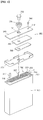
- FIG. 1 shows an exploded perspective view illustrating a secondary battery
- FIG. 2 shows a magnified view illustrating 'A' region of FIG. 1 .
- the secondary battery includes a can 100, an electrode assembly 200 received in the can and including a ceramic coating layer 215, and a cap assembly 300 sealing an opening of the can. It is to be understood that although a rectangular secondary battery is shown in FIGs. 1 and 2 , a battery according to aspects of the present invention may have other shapes and configurations.
- the can 100 may be made of metal having a roughly rectangular parallelepiped shape, but is not limited thereto.
- the can 100 may function as a terminal in itself.
- the can 100 may include a radiant heat area expansion unit (not shown) of a predetermined shape for increasing radiant heat area so as to easily discharge heat generated in the can to the outside.
- the can 100 includes an upper opening 101 through which the electrode assembly 200 is received.
- the cap assembly 300 includes an electrode terminal 330, a cap plate 340, an insulation plate 350, and a terminal plate 360.
- the cap assembly 300 is attached to the upper opening 101 of the can 100 while being insulated from the electrode assembly 200 by a separate insulation case 370, thereby sealing the can 100.
- the electrode terminal 330 functions as a cathode terminal or an anode terminal by being connected to a cathode tab 217 of a cathode to be described later or an anode tab 227 of an anode 220 to be described later.
- the cap plate 340 is formed of a metal plate having a size and shape corresponding to the upper opening 101 of the can 100.
- a terminal hole 341 of a predetermined size is formed in the middle of the cap plate 340.
- the electrode terminal 330 is inserted into the terminal hole 341.
- a tube type gasket 335 that contacts an outer surface of the electrode terminal 330 is also inserted into the terminal hole 341.
- An electrolytic solution injection hole 342 may be formed in a predetermined size at one side of the cap plate 340, and a safety vent (not shown) may be formed at the other side.
- the safety vent may be formed integrally with the cap plate 340 by providing a reduced thickness portion of a sectional surface of the cap plate 340.
- the electrode assembly 200 may include a cathode 210, an anode 220 and a ceramic coating layer 215 formed on at least one of surfaces of the cathode and anode that face to each other, which are wound in a jelly-roll type.
- the secondary battery may further include a separator 230 interposed between the cathode 210 and anode 220 and wound together as shown in the drawing. However, in the present invention, the separator 230 is omitted.
- the cathode 210 includes a cathode collector 211 made of aluminum foil and an cathode active material layer 213 containing a lithium oxide, such as, for example, LiCoO 2 , coated on both surfaces of the cathode collector 211 as a main component.
- Cathode uncoated parts (not shown) are respectively formed at both ends of the cathode collector 211.
- the cathode uncoated parts are regions on one or both surfaces of the cathode 210 where the cathode active material layer 213 is not formed.
- a cathode tab 217 is provided on the cathode uncoated part (not shown).
- An insulation tape 218 is wound on a part of the cathode tab 217 that extends from the electrode assembly 200 to prevent an electrical short.
- the anode 220 includes an anode collector 221 made of thin copper foil and an anode active material layer 223 containing a carbonaceous material such as, for example, graphite coated on both surfaces of the anode collector 221 as a main component.
- Anode uncoated parts (not shown) are respectively formed at both ends of the anode collector 221, where the anode uncoated parts are regions on one or both surfaces of the anode 220 where the anode active material layer 223 is not formed.
- An anode tab 227 is provided on the anode uncoated part (not shown).
- An insulation tape is wound on a part of the anode tab 227 that extends the electrode assembly 200 to prevent an electrical short.
- the ceramic coating layer 215 is formed by coating a ceramic paste made by mixing binder and solvent with ceramic powder onto at least one of the surfaces of the cathode and anode that face to each other.
- the ceramic coating layer 215 may be formed on at least one of electrode surfaces of the cathode and anode that face to each other, i) by forming the ceramic coating layer on each outer surface of the two electrodes, or ii) by forming the ceramic coating layer on each inner surface of the two electrodes, or iii) by forming the ceramic coating layer on both inner and outer surfaces of any one of the two electrodes.
- the ceramic coating layer 215 is formed on both inner and outer surfaces of the cathode 210, but aspects of the present invention are not limited thereto.
- the ceramic coating layer 215 functions as a film separator such that a film separator 230 made from polypropylene (PP) or polyethylene (PE) is omitted.
- the ceramic powder in the ceramic coating layer 215 includes at least one selected from a group including alumina, silica, zirconia, zeolite, magnesia, titanium oxide and barium titanate. Decomposition temperatures of these materials are higher than 1,000°C. Thus, thermal stability of the secondary battery formed by using the ceramic coating layer 215 is prominently improved.
- a polyolefin type film separator 230 has a problem that it contracts or melts at a high temperature, such as a temperature of more than 100°C.
- a high temperature such as a temperature of more than 100°C.
- the ceramic coating layer 215 does not contract or melt when an internal short occurs even if the temperature is increased over 100°C.
- peripheral areas of the film are subsequently contracted or melted by initial heat generation at the time of the internal short.
- the burned or melted portion of the film separator 230 becomes wider, thereby causing a more severe increase of the short.
- the electrode 210 including the ceramic coating layer 215 even if an internal short is generated, merely a small portion is damaged around the short, but the peripheral areas ceramic coating layer 215 do not contract or melt. Thus, the internal short portion does not expand.
- a secondary battery having a high charge/discharge rate may be provided by including a ceramic powder of high porosity.
- the electrolytic solution injection speed is improved because the ceramic coating layer 215 quickly absorbs the electrolytic solution.
- productivity of the secondary battery can be improved.
- the electrolytic solution between the electrode plates may become decomposed and exhausted.
- the ceramic coating layer 215 having a high absorption property absorbs the electrolytic solution around it and supplies the electrolytic solution to the electrode. Thus, the lifetime of the battery is improved.
- the ceramic coating layer 215 is used in place of a polyolefin type film separator 230 made of PP or PE.
- the solvent forming the ceramic paste may include at least one selected from a group of NMP (N-methyl pyrrolidone), cyclohexanone, water, toluene and xylene.
- NMP N-methyl pyrrolidone
- cyclohexanone water, toluene and xylene.
- the solvent is totally evaporated in the drying process after the solvent functions as a dispersing medium for helping to disperse the ceramic powder and binder.
- the ceramic powder and binder forms the ceramic coating layer.
- the binder is used in an amount of less than 10wt% of the total amount of the ceramic powder and binder.
- An optimum weight ratio of the ceramic powder to the binder may vary according to kinds of the ceramic powder and binder.
- the binder may be used in an amount that maintains a minimum adhesive force so as to prevent separation of the ceramic powder.
- the binder is an acrylate group rubber selected from the group consisting of methoxymethyl acrylate, methyl acrylate, methoxyethylacrylate, ethylacrylate, ethoxyethylacrylate, propyl acrylate, butoxyethylacrylate, butyl acrylate, methoxyethoxyethyl acrylate, octylacrylate, vinyl methacrylate, vinyl acrylate, allyl methacrylate, dicyclopentenyloxyethyl acrylate, chloroacetic acid acrylate, 1,1-dimethylpropenylmethacrylate, 1,1-dimethylpropenylacrylate, glycidylacrylate, 3,3-dimethylbutenylmethacrylate, 3,3-dimethylbutenylacrylate, and methyl methacrylate.
- the binder may be butyl acrylate.
- the binder may burn when the temperature of the secondary battery is increased over the decomposition temperature of the binder by generation of an internal short. Therefore, since the ceramic powder is an inorganic metal oxide and has heat resistance to temperatures higher than 1,000°C, it is desirable that the ceramic powder makes up more than 90wt% of the total amount of the ceramic powder and binder.
- the property of the ceramic paste is determined by the ceramic powder.
- the ceramic powder should be uniformly coated without defects for improving thermal stability of the secondary battery as described above.
- the ceramic powder should be coated with an even thickness on the electrode active material without defects such as uncoated parts, pin holes and cracks. Accordingly, the physical properties of the ceramic powder should be controlled. Flowability, stability and dispersibility of the ceramic paste are relevant considerations to be taken into account.
- the quality of the ceramic coating layer is affected by the properties described above.
- flowability refers to a property showing an extent of movement of the paste that can be identified by viscosity. A low viscosity indicates a high flowability, and a high viscosity indicates a low flowability.
- the term "stability” refers to the extent of uniform mixing of the ceramic powder, solvent and binder. If those are not uniformly mixed, layer separations respectively occur between the solvent and binder and ceramic powder, which can be identified by a settlement test. The settlement test is performed by putting the ceramic paste in a mess cylinder and then identifying changes of the layer separation after a predetermined time. Light materials float to the top layer and heavy materials settle in the lower layer. If the solvent, binder and ceramic powder are uniformly mixed, layer separations do not occur.
- the term "dispersibility” refers to that the extent to which the ceramic powder is uniformly dispersed between the solvent and binder without clumping. If the ceramic powder is clumped and not dissolved, the ceramic powder forms large granules. Pin holes, stripes and granular projections may be generated by the presence of the large granule. The dispersibility can be measured by identifying granule sizes in the ceramic paste by using a gap gauge.
- the physical properties as described above are affected by the specific surface area and particle size distribution of the ceramic powder. Accordingly, the lifetime and thermal stability of the secondary battery can be improved by controlling the specific surface area and particle size distribution of the ceramic powder.
- the term "specific surface area” refers to the entire surface area per unit weight, using m 2 /g as the units. Generally, when the specific surface area is large, the powder has a small particle diameter and is more porous. On the other hand, when the specific surface area is small, the powder has a large particle diameter and is less porous. Thus, the specific surface area and porosity are in inverse proportion to the particle size.
- the specific surface area of the ceramic powder is more than 15.0m 2 /g when the binder of a predetermined amount is added, the viscosity of the paste is decreased because the binder is attached to wide surfaces of the particles and binder does not remain in the solvent of the ceramic paste.
- interfacial adhesive force between the ceramic coating layer and the active material layer or adhesive force between the particles of the ceramic powder is decreased when the ceramic coating layer is coated on the active material.
- the specific surface area of the ceramic powder is less than 1.5m 2 /g when the binder of a predetermined amount is added, viscosity of the paste is increased because the binder remains in the solvent of the ceramic paste.
- the remaining binder is hardened to function as stress pulling the active material layer, thereby allowing adhesive force between the electrode collector and active material layer to be decreased.
- the viscosity of the ceramic paste is 20 to 3000cps. If the viscosity of the ceramic paste is less than 20cps, coating may be difficult because of the low viscosity. If the viscosity of the ceramic paste is more than 3000cps, coating may be difficult because of high viscosity.
- the particle size distribution has a D10 value of less than 0.05 ⁇ m, this indicates that many fine particles exist. If the fine particles exist in a large amount, the fine particles tend to clump with each other to form granules. Thus, it is difficult to form a uniformly dispersed paste. The viscosity of the paste is also increased because of the fine particles. In a worst case, the paste may be partially gelated over time. Granules are formed by clumping of the fine particles, and stripes are formed by the granules. Thus, the coating quality is degraded. In the worst case, when the gelated paste is coated, the thickness of the coating is uneven and many defects are generated.
- the particle size distribution has a D90 value of more than 3 ⁇ m, this indicates that large particles exist.
- paste is formed of ceramic powder having the value of D90 more than 3 ⁇ m, large particles settle to a lower layer because of their high density. Thus, layer separation phenomenon occurs in the paste. Accordingly, the paste becomes unstable. In addition, the large particles form granules in themselves. Thus, the coating quality is lowered.
- the particle size distribution of the ceramic powder has a D10 value of more than 0.05 ⁇ m and a D90 value of less than 3.0 ⁇ m.
- the thickness distribution of the ceramic coating layer formed of the ceramic powder having the specific surface area and particle size distribution described above may be less than 10%. A smaller thickness distribution of the ceramic coating layer is more desirable. Thus, a lower limit value for the thickness distribution is not necessary.
- the ceramic powder can be coated on the electrode to uniform thickness without defects such as pin holes and cracks by controlling the specific surface area and particle size distribution of the ceramic powder. Accordingly, generation of an internal short is prevented by preventing current from being concentrated at defective portions. Thus, thermal decomposition of the active material and electrolytic solution and combustion or explosion of the secondary battery can be prevented.
- the ceramic coating layer is coated in uniform thickness.
- the electrode plates are precisely formed in desired size when the electrode plates are wound in a jelly-roll type.
- the ceramic coating layer is formed too thick, it may not be possible to insert the electrode assembly into the can or it may be necessary to apply a strong external force to the electrode assembly.
- the jelly-roll type electrode assembly may be torn or scratched by the rim of the inlet of the can.
- the electrode assembly according to aspects described above can prevent damages as described above.
- Comparison examples 1 to 16 relate to ceramic powders having small specific surface areas (not more than 1.50 m 2 /g) or large specific surface areas (not less than 15.0 m 2 /g).
- Reference examples 1 to 16 relate to ceramic powders having specific surface areas within the range of more than 1.50 m 2 /g and less than 15.0 m 2 /g.
- ceramic pastes were prepared by mixing the ceramic powder with a binder (butyl acrylate) and a solvent (NMP), wherein the amount of the ceramic powder was 95wt%, the amount of binder was 5wt%, and the amount of solvent was 400wt% of the weight of the ceramic powder and binder.
- NMP solvent
- flowability, stability and dispersibility of each ceramic paste were measured, and then the ceramic coating layer was coated onto the active material layer of the anode plate and dried.
- the coating quality of the ceramic coating layer can be identified by thickness uniformity and formation of defects. In other words, the coating quality is good when the thickness is uniform and defects do not exist.
- Batteries were constructed according to FIGS. 2 , each having a ceramic coating layer formed by coating one of the ceramic pastes of the comparison examples or reference examples on the both surfaces of the cathode.
- the positive active material layer 213 comprised LiCoO 2
- the negative active material layer 223 comprised graphite.
- the batteries constructed according to FIG. 2 comprise a polyolefin separator 230.
- the separator 230 is omitted and the Examples below are therefore provided for reference.
- the specific surface area of the ceramic powder was measured by ASAP2020 surface analyzer from Micromeritics Co. (USA) using N 2 gas.
- the viscosity (cps) of the ceramic paste was measured at 25 °C with a Brookfield (USA) DV-II+PRO viscometer at 50rpm by using #62 spindle.
- the measured viscosity of the ceramic paste was less than 20 cps, it was also noted that forming a coating with the ceramic paste was difficult. In such as case, the result was recorded as NG.
- Ceramic pastes having a viscosity of 20 through 3000cps were suitable for forming a coating, and ceramic pastes having a viscosity within this range were marked as OK.
- the viscosity of a ceramic paste was more than 3000 cps forming a coating was difficult, and the result was marked as NG.
- the ceramic paste was coated to a desired thickness by controlling a gap of a gap gauge. Then, the formation of ceramic paste granules was identified by the naked eye. If a stripe was formed in the coating by the presence of a granule larger than the gap of the gap gauge, the sample was marked as NG. If stripes did not exist, the sample was marked as OK.
- the thickness uniformity of the ceramic coating layer was measured after the ceramic paste was coated onto a thin copper foil base material and then dried. A sample was marked as OK when the thickness distribution was less than 10%, and marked as NG when the thickness distribution was not less than 10%.
- Pin holes, cracks, uncoated parts and stripes were defined as defects.
- a sample was marked as OK when an area of the defect was less than 5% of a normal area, and marked as NG when the area of the defect was not less than 5% of the normal area.
- the nail penetration test was conducted by overcharging the battery by 120% and penetrating the battery with a nail. Thirty batteries were tested for each example. If more than 24 batteries out of 30 did not explode, the result was marked as OK; otherwise, the result was marked as NG.
- the 150°C penetration test was conducted by charging a battery to 100%, heating the battery to 150°C at a rate of 5°C/min and then leaving the battery at 150°C for one hour. Thirty batteries were tested for each example. If more than 24 batteries out of 30 did not explode, the result was marked as OK; otherwise, the result was marked as NG.
- the bar crush test was conducted by charging a battery to 100%, placing an iron bar having a diameter of 5mm on the battery and dropping a 9kN iron mass on the iron bar from a 1m height. Thirty batteries were tested for each example. If more than 24 batteries out of 30 did not explode, the result was marked as OK; otherwise, the result was marked as NG.
- the particle size distribution of the ceramic powder was measured by an HRA model particle size distribution analyzer from Microtrack company (Japan). D10 and D90 values respectively indicate particle size distributions of relative particle contents of 10% and 90%. Measurement conditions for the viscosity of ceramic paste, layer separation, formation of granules, thickness uniformity of the ceramic coating layer and defects of the ceramic coating layer were the same as the Experiment 1.
- Comparison examples 17, 19, 21, 23, 25, 27, 29 and 31 relate to ceramic powders having a D10 particle size distribution of not more than 0.05 ⁇ m
- Comparison examples 18, 20, 22, 24, 26, 28, 30 and 32 relate to ceramic particles having a D90 particle size distribution of not less than 3 ⁇ m
- Reference examples 17 to 32 relate to ceramic powders having a D10 value of more than 0.05 ⁇ m and a D90 value of less than 3 ⁇ m.
- Comparison examples 33 to 48 relate to ceramic powders having specific surface areas not more than 1.5 m2/g or not less than 15.0 m2/g, and particle size distribution values of D10 not more than 0.05 ⁇ m or D90 not less than 3 ⁇ m.
- Reference examples 33 to 48 relate to ceramic powders having specific surface areas more than 1.5m2/g and less than 15m2/g, and the particle size distribution values of D10 more than 0.05 ⁇ m or D90 less than 3 ⁇ m.
- the electrode assembly and secondary battery including the electrode assembly according to aspects of the present invention produces the following effects.
- the ceramic powder can be coated onto the electrode to a uniform thickness without defects such as pin holes and cracks by controlling the specific surface area and particle size distribution of the ceramic powder.
- the ceramic coating layer is formed on the electrode in a uniform thickness without defects.
- expansion of internal short circuits can be prevented by preventing current from being concentrated at defective portions even when the separator melts to cause an internal short.
- thermal decomposition of the active material and electrolytic solution and combustion or explosion of the secondary battery can be prevented by preventing expansion of the internal short.
Landscapes
- Chemical & Material Sciences (AREA)
- Engineering & Computer Science (AREA)
- Chemical Kinetics & Catalysis (AREA)
- Electrochemistry (AREA)
- General Chemical & Material Sciences (AREA)
- Manufacturing & Machinery (AREA)
- Materials Engineering (AREA)
- Composite Materials (AREA)
- Battery Electrode And Active Subsutance (AREA)
- Cell Separators (AREA)
- Secondary Cells (AREA)
Claims (4)
- Ensemble d'électrodes comprenant :une cathode (210) comprenant une couche de matériau actif de cathode (213) ;une anode (220) comprenant une couche de matériau actif d'anode (223) ;la cathode (210) et l'anode (220) ayant chacune des surfaces se faisant face, et une couche de revêtement en céramique formée sur au moins l'une des surfaces de la cathode (210) et de l'anode (220) qui se font mutuellement face, la couche de revêtement en céramique comprenant une poudre de céramique et un liant,où la distribution de granulométrie de la poudre de céramique a une valeur D10 supérieure à 0,05 µm et une valeur D90 inférieure à 3,0 µm ; et où la couche de revêtement en céramique peut être obtenue par dépôt sous forme de revêtement d'une pâte de céramique ayant une viscosité de 20 à 3000 cps sur au moins l'une de la cathode (210) et de l'anode (220), la pâte comprenant la poudre de céramique, le liant et un solvant ; et où la quantité du liant est inférieure à 10% en poids de la quantité totale du liant et de la poudre de céramique, et où la quantité de la poudre de céramique est supérieure à 90% en poids de la quantité totale du liant et de la poudre de céramique ;où l'ensemble d'électrodes n'a pas de séparateur en film de polyoléfine entre l'anode (220) et la cathode (210) ;et où le liant est un caoutchouc contenant un groupe acrylate choisi dans l'ensemble constitué par l'acrylate de méthoxyméthyle, l'acrylate de méthyle, l'acrylate de méthoxyéthyle, l'acrylate d'éthyle, l'acrylate d'éthoxy-éthyle, l'acrylate de propyle, l'acrylate de butoxyéthyle, l'acrylate de butyle, l'acrylate de méthoxyéthoxyéthyle, l'acrylate d'octyle, le méthacrylate de vinyle, l'acrylate de vinyle, le méthacrylate d'allyle, l'acrylate de dicyclo-pentényloxyéthyle, l'acrylate d'acide chloroacétique, le méthacrylate de 1,1-diméthylpropényle, l'acrylate de 1,1-diméthylpropényle, l'acrylate de glycidyle, le méthacrylate de 3,3-diméthylbutényle, l'acrylate de 3,3-diméthylbutényle, et le méthacrylate de méthyle.
- Ensemble d'électrodes selon la revendication 1, où la distribution d'épaisseur de la couche de revêtement en céramique est inférieure à 10%.
- Ensemble d'électrodes selon la revendication 1 ou 2, où la poudre de céramique est au moins l'une choisie dans l'ensemble constitué par l'alumine, la silice, la zircone, la zéolite, la magnésie, l'oxyde de titane et le titanate de baryum.
- Batterie secondaire comprenant :un ensemble d'électrodes (200) selon l'une quelconque des revendications précédentes ;un boîtier (100) qui reçoit l'ensemble d'électrodes (200) ; etun ensemble de couvercle (300) qui scelle le boîtier (100) .
Applications Claiming Priority (1)
| Application Number | Priority Date | Filing Date | Title |
|---|---|---|---|
| KR1020080003489A KR100983161B1 (ko) | 2008-01-11 | 2008-01-11 | 전극조립체 및 이를 구비한 이차전지 |
Publications (2)
| Publication Number | Publication Date |
|---|---|
| EP2079121A1 EP2079121A1 (fr) | 2009-07-15 |
| EP2079121B1 true EP2079121B1 (fr) | 2019-06-05 |
Family
ID=40561755
Family Applications (1)
| Application Number | Title | Priority Date | Filing Date |
|---|---|---|---|
| EP09150049.6A Active EP2079121B1 (fr) | 2008-01-11 | 2009-01-05 | Ensemble d'électrode et batterie secondaire en disposant |
Country Status (6)
| Country | Link |
|---|---|
| US (1) | US8399133B2 (fr) |
| EP (1) | EP2079121B1 (fr) |
| JP (1) | JP5090380B2 (fr) |
| KR (1) | KR100983161B1 (fr) |
| CN (1) | CN101499523A (fr) |
| HU (1) | HUE045114T2 (fr) |
Families Citing this family (32)
| Publication number | Priority date | Publication date | Assignee | Title |
|---|---|---|---|---|
| KR101111710B1 (ko) * | 2008-01-29 | 2012-03-13 | 히다치 막셀 가부시키가이샤 | 절연층 형성용 슬러리, 전기화학소자용 세퍼레이터 및 그 제조방법, 및 전기화학소자 |
| US20100136424A1 (en) * | 2009-07-17 | 2010-06-03 | Tesla Motors, Inc. | Multi-wall battery for maintaining cell wall integrity during thermal runaway |
| JP5415215B2 (ja) * | 2009-10-02 | 2014-02-12 | タテホ化学工業株式会社 | 分散性に優れる酸化マグネシウム粉末及びその製造方法 |
| US9401784B2 (en) | 2009-10-21 | 2016-07-26 | Qualcomm Incorporated | Time and frequency acquisition and tracking for OFDMA wireless systems |
| US10111111B2 (en) | 2009-11-19 | 2018-10-23 | Qualcomm Incorporated | Per-cell timing and/or frequency acquisition and their use on channel estimation in wireless networks |
| KR101093916B1 (ko) * | 2009-12-15 | 2011-12-13 | 삼성에스디아이 주식회사 | 세퍼레이터, 그 제조방법 및 리튬 이차전지 |
| ES2713517T3 (es) | 2010-07-19 | 2019-05-22 | Optodot Corp | Separadores para células electroquímicas |
| CN103035920B (zh) * | 2011-09-30 | 2016-01-20 | 深圳市比克电池有限公司 | 一种锂离子电池及其制备方法 |
| CN103035940B (zh) * | 2011-09-30 | 2016-09-07 | 深圳市比克电池有限公司 | 一种锂离子电池及其制备方法 |
| JP5614592B2 (ja) * | 2011-10-12 | 2014-10-29 | トヨタ自動車株式会社 | 二次電池用電極の製造方法 |
| TWI482340B (zh) | 2011-12-14 | 2015-04-21 | Ind Tech Res Inst | 鋰二次電池的電極模組 |
| WO2013147006A1 (fr) * | 2012-03-30 | 2013-10-03 | 日本ゼオン株式会社 | Membrane poreuse pour une pile rechargeable, bouillie pour membrane poreuse pour une pile rechargeable, particules non conductrices, électrode pour une pile rechargeable, séparateur pour une pile rechargeable et pile rechargeable |
| KR101511732B1 (ko) * | 2012-04-10 | 2015-04-13 | 주식회사 엘지화학 | 다공성 코팅층이 형성된 전극, 이의 제조방법 및 이를 포함하는 전기화학소자 |
| KR101739211B1 (ko) | 2012-07-27 | 2017-05-23 | 스미또모 가가꾸 가부시끼가이샤 | 알루미나 슬러리 및 그 제조 방법 그리고 도공액 |
| WO2014084681A1 (fr) * | 2012-11-30 | 2014-06-05 | 주식회사 엘지화학 | Membrane de séparation de batterie secondaire contenant des couches de revêtement à double porosité en particules inorganiques ayant différentes propriétés de surface, batterie secondaire l'intégrant et procédé de fabrication d'une membrane de séparation |
| KR101535199B1 (ko) | 2012-11-30 | 2015-07-09 | 주식회사 엘지화학 | 개선된 분산성을 갖는 슬러리 및 그의 용도 |
| US20140170479A1 (en) * | 2012-12-14 | 2014-06-19 | Bill Todorof | Saline battery |
| US9899682B2 (en) | 2013-07-30 | 2018-02-20 | Lg Chem, Ltd. | Electrode including coating layer for preventing reaction with electrolyte solution |
| TWI609518B (zh) * | 2013-12-09 | 2017-12-21 | Lg化學股份有限公司 | 分散性經改善之淤漿及其用途 |
| TWI580098B (zh) | 2013-12-10 | 2017-04-21 | 財團法人工業技術研究院 | 用於鋰電池之有機-無機複合層及電極模組 |
| CN104449011A (zh) * | 2014-12-04 | 2015-03-25 | 中航锂电(洛阳)有限公司 | 一种锂离子电池绝缘涂料、制备方法及使用该绝缘涂料的极片和锂离子电池 |
| JP6415312B2 (ja) * | 2014-12-26 | 2018-10-31 | 積水化学工業株式会社 | セパレータ及び電気化学デバイス |
| CN105789537A (zh) * | 2016-03-25 | 2016-07-20 | 江苏富朗特新能源有限公司 | 锂离子电池正负极极卷外置陶瓷层组分及应用方法 |
| CN107316977A (zh) * | 2017-06-07 | 2017-11-03 | 天津市捷威动力工业有限公司 | 一种新型锂离子动力电池负极以及锂离子动力电池 |
| KR102132756B1 (ko) * | 2017-12-06 | 2020-07-13 | 주식회사 엘지화학 | 이차전지 분리막 코팅용 슬러리 조성물 및 이를 이용한 이차전지 분리막 |
| JP7047465B2 (ja) | 2018-03-02 | 2022-04-05 | 三洋電機株式会社 | 非水電解質二次電池およびその製造方法 |
| CN108649182A (zh) * | 2018-05-11 | 2018-10-12 | 江西中汽瑞华新能源科技有限公司 | 一种高安全性锂离子电池 |
| CN108878775A (zh) * | 2018-06-29 | 2018-11-23 | 桑顿新能源科技有限公司 | 一种安全补锂复合负极极片及其制备方法 |
| JP6634133B2 (ja) * | 2018-09-26 | 2020-01-22 | 積水化学工業株式会社 | セパレータ及び電気化学デバイス |
| EP3690993B1 (fr) * | 2019-02-01 | 2023-10-04 | Samsung SDI Co., Ltd. | Compositions pour la formation d'une couche isolante poreuse, électrode pour batterie rechargeable à électrolyte non aqueux, batterie rechargeable comprenant l'électrode et procédé de fabrication de l'électrode |
| CN110957464B (zh) * | 2019-09-25 | 2021-08-17 | 东莞赣锋电子有限公司 | 一种涂覆极片的制备方法 |
| WO2024036849A1 (fr) * | 2022-08-19 | 2024-02-22 | Techtronic Cordless Gp | Électrode à revêtement céramique et batterie au lithium-ion la comprenant |
Citations (2)
| Publication number | Priority date | Publication date | Assignee | Title |
|---|---|---|---|---|
| EP1667255A1 (fr) * | 2003-09-18 | 2006-06-07 | Matsushita Electric Industrial Co., Ltd. | Accumulateur lithium-ion |
| US20070218362A1 (en) * | 2004-04-23 | 2007-09-20 | Akira Nagasaki | Lithium Ion Secondary Battery |
Family Cites Families (20)
| Publication number | Priority date | Publication date | Assignee | Title |
|---|---|---|---|---|
| US6001761A (en) | 1994-09-27 | 1999-12-14 | Nippon Shokubai Co., Ltd. | Ceramics sheet and production method for same |
| JP3359164B2 (ja) | 1994-10-19 | 2002-12-24 | キヤノン株式会社 | 二次電池 |
| US5914094A (en) * | 1995-12-19 | 1999-06-22 | Samsung Display Devices Co., Ltd. | Process for preparing cathode active material by a sol-gel method |
| JPH10223195A (ja) | 1997-02-03 | 1998-08-21 | Asahi Chem Ind Co Ltd | 新規な電池 |
| JP2001110454A (ja) | 1999-10-08 | 2001-04-20 | Matsushita Electric Ind Co Ltd | リチウムイオン二次電池 |
| US6432586B1 (en) | 2000-04-10 | 2002-08-13 | Celgard Inc. | Separator for a high energy rechargeable lithium battery |
| KR100789558B1 (ko) | 2000-06-07 | 2007-12-28 | 상요 지에스 소프트 에너지 가부시끼가이샤 | 전지 |
| DE10238941B4 (de) | 2002-08-24 | 2013-03-28 | Evonik Degussa Gmbh | Elektrischer Separator, Verfahren zu dessen Herstellung und Verwendung in Lithium-Hochleistungsbatterien sowie eine den Separator aufweisende Batterie |
| US7422825B2 (en) * | 2004-03-30 | 2008-09-09 | Matsushita Electric Industrial Co., Ltd. | Nonaqueous electrolyte secondary battery |
| JP4763253B2 (ja) | 2004-05-17 | 2011-08-31 | パナソニック株式会社 | リチウムイオン二次電池 |
| KR100659820B1 (ko) * | 2004-11-17 | 2006-12-19 | 삼성에스디아이 주식회사 | 리튬 이온 이차 전지 |
| KR100659851B1 (ko) | 2005-04-27 | 2006-12-19 | 삼성에스디아이 주식회사 | 리튬 이차 전지 |
| JP4184404B2 (ja) | 2005-12-08 | 2008-11-19 | 日立マクセル株式会社 | 電気化学素子用セパレータおよび電気化学素子 |
| JP5055865B2 (ja) | 2006-07-19 | 2012-10-24 | パナソニック株式会社 | リチウムイオン二次電池 |
| KR100778975B1 (ko) | 2007-03-08 | 2007-11-28 | 삼성에스디아이 주식회사 | 리튬 이차 전지 |
| KR100908977B1 (ko) | 2007-03-29 | 2009-07-22 | 삼성에스디아이 주식회사 | 이차전지의 전극 조립체 |
| KR101407772B1 (ko) * | 2007-05-25 | 2014-06-18 | 삼성에스디아이 주식회사 | 전극조립체 및 그를 이용한 이차전지 |
| KR100876271B1 (ko) * | 2007-05-29 | 2008-12-26 | 삼성에스디아이 주식회사 | 리튬 이차 전지 |
| KR20080105853A (ko) | 2007-06-01 | 2008-12-04 | 삼성에스디아이 주식회사 | 세라믹층이 코팅된 양극 또는 음극을 포함하는리튬이차전지 |
| KR100876268B1 (ko) | 2007-10-09 | 2008-12-26 | 삼성에스디아이 주식회사 | 리튬 이차전지 |
-
2008
- 2008-01-11 KR KR1020080003489A patent/KR100983161B1/ko active IP Right Grant
- 2008-12-18 US US12/338,145 patent/US8399133B2/en active Active
-
2009
- 2009-01-05 EP EP09150049.6A patent/EP2079121B1/fr active Active
- 2009-01-05 HU HUE09150049A patent/HUE045114T2/hu unknown
- 2009-01-06 CN CNA2009100003507A patent/CN101499523A/zh active Pending
- 2009-01-13 JP JP2009004716A patent/JP5090380B2/ja active Active
Patent Citations (2)
| Publication number | Priority date | Publication date | Assignee | Title |
|---|---|---|---|---|
| EP1667255A1 (fr) * | 2003-09-18 | 2006-06-07 | Matsushita Electric Industrial Co., Ltd. | Accumulateur lithium-ion |
| US20070218362A1 (en) * | 2004-04-23 | 2007-09-20 | Akira Nagasaki | Lithium Ion Secondary Battery |
Also Published As
| Publication number | Publication date |
|---|---|
| US20090181300A1 (en) | 2009-07-16 |
| HUE045114T2 (hu) | 2019-12-30 |
| EP2079121A1 (fr) | 2009-07-15 |
| JP2009170421A (ja) | 2009-07-30 |
| CN101499523A (zh) | 2009-08-05 |
| US8399133B2 (en) | 2013-03-19 |
| KR20090077502A (ko) | 2009-07-15 |
| KR100983161B1 (ko) | 2010-09-20 |
| JP5090380B2 (ja) | 2012-12-05 |
Similar Documents
| Publication | Publication Date | Title |
|---|---|---|
| EP2079121B1 (fr) | Ensemble d'électrode et batterie secondaire en disposant | |
| US7396612B2 (en) | Lithium ion secondary battery | |
| KR100732803B1 (ko) | 리튬이온 2차전지 | |
| KR100450109B1 (ko) | 비수계 이차전지와 그 제조법 | |
| KR100992248B1 (ko) | 리튬이온 이차전지용 전극 | |
| EP4160731A1 (fr) | Feuille d'électrode négative et utilisation associée | |
| US20090169986A1 (en) | Non-aqueous secondary battery and method for producing the same | |
| JPWO2005098997A1 (ja) | 非水電解液二次電池 | |
| WO2005117169A1 (fr) | Accumulateur non aqueux à bobines et électrode plane utilisée dans celle-ci | |
| EP2048734A1 (fr) | Ensemble d'électrode et batterie secondaire | |
| KR100908977B1 (ko) | 이차전지의 전극 조립체 | |
| US8349482B2 (en) | Electrode assembly and secondary battery with the same | |
| EP4246701A1 (fr) | Batterie, dispositif électronique et appareil mobile | |
| US20090208838A1 (en) | Electrode assembly and secondary battery having the same | |
| US20080206645A1 (en) | Non-aqueous electrolyte secondary battery and method for producing same | |
| KR20120133409A (ko) | 이차전지용 분리막 및 이를 포함한 리튬 이차전지 | |
| JP6848644B2 (ja) | リチウムイオン二次電池 | |
| KR20140015841A (ko) | 이중 코팅층이 형성된 전극을 포함하는 리튬이차전지 | |
| KR100634901B1 (ko) | 비수(非水) 전해질 전지 | |
| KR101351733B1 (ko) | 전극 조립체와 이를 구비하는 이차 전지 및 그 제조 방법 | |
| KR101308195B1 (ko) | 전극조립체와 이를 포함하는 리튬 이차전지 및 리튬이차전지의 제조방법 | |
| KR100749626B1 (ko) | 이차전지 | |
| JPH09265990A (ja) | 非水電解液電池及びその製造方法 | |
| KR20230055420A (ko) | 안전성이 향상된 이차전지 |
Legal Events
| Date | Code | Title | Description |
|---|---|---|---|
| PUAI | Public reference made under article 153(3) epc to a published international application that has entered the european phase |
Free format text: ORIGINAL CODE: 0009012 |
|
| 17P | Request for examination filed |
Effective date: 20090105 |
|
| AK | Designated contracting states |
Kind code of ref document: A1 Designated state(s): AT BE BG CH CY CZ DE DK EE ES FI FR GB GR HR HU IE IS IT LI LT LU LV MC MK MT NL NO PL PT RO SE SI SK TR |
|
| AX | Request for extension of the european patent |
Extension state: AL BA RS |
|
| AKX | Designation fees paid |
Designated state(s): DE FR GB HU |
|
| 17Q | First examination report despatched |
Effective date: 20170215 |
|
| GRAJ | Information related to disapproval of communication of intention to grant by the applicant or resumption of examination proceedings by the epo deleted |
Free format text: ORIGINAL CODE: EPIDOSDIGR1 |
|
| GRAP | Despatch of communication of intention to grant a patent |
Free format text: ORIGINAL CODE: EPIDOSNIGR1 |
|
| GRAP | Despatch of communication of intention to grant a patent |
Free format text: ORIGINAL CODE: EPIDOSNIGR1 |
|
| INTG | Intention to grant announced |
Effective date: 20190220 |
|
| GRAS | Grant fee paid |
Free format text: ORIGINAL CODE: EPIDOSNIGR3 |
|
| GRAA | (expected) grant |
Free format text: ORIGINAL CODE: 0009210 |
|
| AK | Designated contracting states |
Kind code of ref document: B1 Designated state(s): DE FR GB HU |
|
| REG | Reference to a national code |
Ref country code: GB Ref legal event code: FG4D |
|
| REG | Reference to a national code |
Ref country code: DE Ref legal event code: R096 Ref document number: 602009058593 Country of ref document: DE |
|
| REG | Reference to a national code |
Ref country code: HU Ref legal event code: AG4A Ref document number: E045114 Country of ref document: HU |
|
| REG | Reference to a national code |
Ref country code: DE Ref legal event code: R097 Ref document number: 602009058593 Country of ref document: DE |
|
| PLBE | No opposition filed within time limit |
Free format text: ORIGINAL CODE: 0009261 |
|
| STAA | Information on the status of an ep patent application or granted ep patent |
Free format text: STATUS: NO OPPOSITION FILED WITHIN TIME LIMIT |
|
| 26N | No opposition filed |
Effective date: 20200306 |
|
| REG | Reference to a national code |
Ref country code: DE Ref legal event code: R079 Ref document number: 602009058593 Country of ref document: DE Free format text: PREVIOUS MAIN CLASS: H01M0002160000 Ipc: H01M0050409000 |
|
| P01 | Opt-out of the competence of the unified patent court (upc) registered |
Effective date: 20230528 |
|
| PGFP | Annual fee paid to national office [announced via postgrant information from national office to epo] |
Ref country code: GB Payment date: 20231221 Year of fee payment: 16 |
|
| PGFP | Annual fee paid to national office [announced via postgrant information from national office to epo] |
Ref country code: FR Payment date: 20231222 Year of fee payment: 16 |
|
| PGFP | Annual fee paid to national office [announced via postgrant information from national office to epo] |
Ref country code: HU Payment date: 20240111 Year of fee payment: 16 Ref country code: DE Payment date: 20231228 Year of fee payment: 16 |