EP2075395B2 - Verwendung eines Schließhilfsantriebs für ein Kraftfahrzeugschloss - Google Patents
Verwendung eines Schließhilfsantriebs für ein Kraftfahrzeugschloss Download PDFInfo
- Publication number
- EP2075395B2 EP2075395B2 EP08019787.4A EP08019787A EP2075395B2 EP 2075395 B2 EP2075395 B2 EP 2075395B2 EP 08019787 A EP08019787 A EP 08019787A EP 2075395 B2 EP2075395 B2 EP 2075395B2
- Authority
- EP
- European Patent Office
- Prior art keywords
- drive
- locking
- spindle
- auxiliary
- bowden cable
- Prior art date
- Legal status (The legal status is an assumption and is not a legal conclusion. Google has not performed a legal analysis and makes no representation as to the accuracy of the status listed.)
- Active
Links
Images


Classifications
-
- E—FIXED CONSTRUCTIONS
- E05—LOCKS; KEYS; WINDOW OR DOOR FITTINGS; SAFES
- E05B—LOCKS; ACCESSORIES THEREFOR; HANDCUFFS
- E05B81/00—Power-actuated vehicle locks
- E05B81/24—Power-actuated vehicle locks characterised by constructional features of the actuator or the power transmission
- E05B81/25—Actuators mounted separately from the lock and controlling the lock functions through mechanical connections
-
- E—FIXED CONSTRUCTIONS
- E05—LOCKS; KEYS; WINDOW OR DOOR FITTINGS; SAFES
- E05B—LOCKS; ACCESSORIES THEREFOR; HANDCUFFS
- E05B79/00—Mounting or connecting vehicle locks or parts thereof
- E05B79/10—Connections between movable lock parts
- E05B79/20—Connections between movable lock parts using flexible connections, e.g. Bowden cables
-
- E—FIXED CONSTRUCTIONS
- E05—LOCKS; KEYS; WINDOW OR DOOR FITTINGS; SAFES
- E05B—LOCKS; ACCESSORIES THEREFOR; HANDCUFFS
- E05B81/00—Power-actuated vehicle locks
- E05B81/12—Power-actuated vehicle locks characterised by the function or purpose of the powered actuators
- E05B81/20—Power-actuated vehicle locks characterised by the function or purpose of the powered actuators for assisting final closing or for initiating opening
-
- E—FIXED CONSTRUCTIONS
- E05—LOCKS; KEYS; WINDOW OR DOOR FITTINGS; SAFES
- E05B—LOCKS; ACCESSORIES THEREFOR; HANDCUFFS
- E05B81/00—Power-actuated vehicle locks
- E05B81/24—Power-actuated vehicle locks characterised by constructional features of the actuator or the power transmission
- E05B81/32—Details of the actuator transmission
- E05B81/34—Details of the actuator transmission of geared transmissions
- E05B81/38—Planetary gears
-
- Y—GENERAL TAGGING OF NEW TECHNOLOGICAL DEVELOPMENTS; GENERAL TAGGING OF CROSS-SECTIONAL TECHNOLOGIES SPANNING OVER SEVERAL SECTIONS OF THE IPC; TECHNICAL SUBJECTS COVERED BY FORMER USPC CROSS-REFERENCE ART COLLECTIONS [XRACs] AND DIGESTS
- Y10—TECHNICAL SUBJECTS COVERED BY FORMER USPC
- Y10T—TECHNICAL SUBJECTS COVERED BY FORMER US CLASSIFICATION
- Y10T292/00—Closure fasteners
- Y10T292/08—Bolts
- Y10T292/1043—Swinging
- Y10T292/1075—Operating means
- Y10T292/1082—Motor
-
- Y—GENERAL TAGGING OF NEW TECHNOLOGICAL DEVELOPMENTS; GENERAL TAGGING OF CROSS-SECTIONAL TECHNOLOGIES SPANNING OVER SEVERAL SECTIONS OF THE IPC; TECHNICAL SUBJECTS COVERED BY FORMER USPC CROSS-REFERENCE ART COLLECTIONS [XRACs] AND DIGESTS
- Y10—TECHNICAL SUBJECTS COVERED BY FORMER USPC
- Y10T—TECHNICAL SUBJECTS COVERED BY FORMER US CLASSIFICATION
- Y10T70/00—Locks
- Y10T70/50—Special application
- Y10T70/5889—For automotive vehicles
Definitions
- the invention relates to an auxiliary locking drive for a motor vehicle lock with the features of the preamble of claim 1.
- motor vehicle lock covers all types of door/hood/lid or flap locks.
- the motor vehicle lock is equipped with the usual locking elements, lock latch and pawl, whereby the pawl holds the lock latch in a main locking position and in a pre-locking position. The pawl is then in a retracted position.
- the lock latch can be brought into holding engagement with a locking wedge or the like on the body. In this case, the locking wedge or the like is to be attributed to the motor vehicle lock.
- auxiliary locking function in which the vehicle lock is motor-driven from a pre-locking state to a main locking state.
- the advantage here is that the user only has to adjust the vehicle door to a pre-locking state to close it, and this can be done with relatively little effort.
- Door seal counterpressures are not yet effective here. Only the adjustment from the pre-locking state to the main locking state involves compressing the door seal and thus requires considerable effort, which is done by means of an auxiliary locking drive.
- the locking aid function There are already various variants for the implementation of the locking aid function.
- One variant ( DE 39 35 804 C2 ) provides that the locking wedge, which works together with the lock latch, can be moved by a motor to close the vehicle door.
- the lock latch can be adjusted by means of the locking aid from the pre-locking position to the main locking position and thus the vehicle lock as a whole can be adjusted from the pre-locking state to the main locking state.
- the auxiliary closing drive is activated when the lock latch reaches the pre-locking position.
- a control unit in the form of an auxiliary closing control is provided for this purpose.
- a closing auxiliary drive is known in which a spindle, to which a Bowden cable is attached, is moved linearly by an electric motor.
- a gear transmission is provided between the motor and the spindle.
- the DE 31 46 804 A1 shows an actuating element for a central door locking system for motor vehicle doors, in which an electric motor directly drives a threaded spindle.
- the threaded spindle is equipped with a small pitch angle.
- An axially displaceable spindle nut is guided on the threaded spindle in guide grooves in a rotationally fixed manner. By turning the threaded spindle, a locking part can be brought into the unlocking and locking position.
- the DE 103 20 660 A1 shows an actuator, in particular for central locking systems, in which a spindle with a drive wheel arranged on one side is rotatably mounted in a first housing part.
- the drive wheel is in engagement with a pinion of an electric motor, the longitudinal axis of which runs parallel to the longitudinal axis of the spindle.
- the spindle engages in a tappet which is provided with a thread complementary to the spindle.
- the auxiliary locking drive is arranged separately from the motor vehicle lock and is coupled to the motor vehicle lock via a Bowden cable. This solves the installation space problem in the area of the motor vehicle lock in a satisfactory manner and corresponds to a modular design.
- the invention is therefore based on the problem of designing and developing the known closing auxiliary drive in such a way that the installation space requirement and the weight of the closing auxiliary drive are reduced.
- auxiliary closing drive with a feed gear for generating a linear drive movement, which is designed as a spindle-spindle nut gear, with the appropriate design and the provision of an anti-twist device formed by a nose that runs in a longitudinal guide, results in minimal installation space requirements. Furthermore, such an arrangement can be implemented with a minimum number of components, which also results in low weight.
- the proposed auxiliary closing drive can be easily designed or parameterized for the respective application. Different applications can require different forces, speeds and feeds, which accordingly leads to different drive motors, intermediate gears or feed gears. Depending on the configuration, the drive housing and, if necessary, the Bowden cable end piece must be adapted.
- Fig. 1 The structural design of a proposed auxiliary closing drive shown here applies to all Fig. 2 to 4 illustrated embodiments.
- This auxiliary locking drive is assigned to a motor vehicle lock 1.
- motor vehicle lock With regard to the broad understanding of the term “motor vehicle lock”, reference may be made to the general part of the description.
- the locking auxiliary drive has its own drive housing 2 and is arranged separately from the motor vehicle lock 1 when installed. It can be seen from the illustration in Fig. 1 that the auxiliary locking drive is coupled to the motor vehicle lock 1 via a transmission means 3.
- the auxiliary locking drive has a drive motor 4, whereby in the assembled state a linear drive movement can be generated by means of the drive motor 4 and transmitted to the motor vehicle lock 1 via the transmission means 3.
- the motor vehicle lock 1 can be transferred from the pre-locking state to the main locking state by means of this linear drive movement.
- Fig. 2 to 4 show in three embodiments that the auxiliary closing drive has a feed gear 5 connected downstream of the drive motor 4 for generating the linear drive movement and that the feed gear 5 in all embodiments is designed as a spindle-spindle nut gear with a spindle 6 and a spindle nut 7.
- the motor vehicle lock 1 can be assigned to virtually any locking element in a motor vehicle lock. Preferably, however, the motor vehicle lock 1 is assigned to a motor vehicle door or a motor vehicle flap.
- the motor vehicle door can also be a sliding door.
- the transmission means 3 is designed as a Bowden cable, which has a Bowden cable core 8 and a Bowden cable sheath 9.
- the drive movement in this case is a linear drive movement. Accordingly, the use of a spindle-spindle nut gear for the feed gear 5 is essential. Depending on the design of the motor vehicle lock 1, an adapted design of the auxiliary locking drive is necessary with regard to the extent of the drive movement and the level of the drive force.
- the motor vehicle lock 1 has the locking elements lock latch 10 and pawl 11 as well as a locking block 12 assigned to the lock latch 10. The basic interaction of these components was explained in the general part of the description.
- the lock latch 10 can be brought into a pre-locking position (not shown) and into the main locking position shown.
- the lock latch 10 has a pre-locking position 13 and a main locking position 14, which can each be brought into engagement with an engagement section 15 of the pawl 11.
- the auxiliary locking drive is coupled in the mounted state to the lock latch 10 in terms of drive technology, and that the lock latch 10 is moved away from the Pre-locking position into the main locking position and thus the motor vehicle lock 1 as a whole can be brought from the pre-locking state into the main locking state.
- the auxiliary locking drive preferably first causes an adjustment of the lock latch 10 into an over-stroke position so that the pawl 11 can fall in.
- the lock latch 10 then falls back into the main locking position and is held there by the pawl 11.
- the Bowden cable core 8 of the Bowden cable 3 is preferably coupled to the lock latch 10.
- the auxiliary locking drive does not act on the lock latch 10, but on the locking block 12.
- the locking block 12 can itself be brought into a pre-locking position and a main locking position, that the auxiliary locking drive is coupled to the locking block 12 in the assembled state in terms of drive technology and that the locking block 12 can be brought from the pre-locking position to the main locking position by the drive movement generated by the auxiliary locking drive and thus the motor vehicle lock 1 as a whole can be brought from the pre-locking state to the main locking state.
- Both variants of motor vehicle locks 1 require the transmission of a drive movement via the transmission means 3, here via the Bowden cable 3.
- the range of movement and the required force vary depending on the design, which has corresponding effects on the design of the locking auxiliary drive.
- spindle-spindle nut gear as well as the terms “spindle” and “spindle nut” are to be understood broadly in connection with the feed gear 5. Basically, it is intended that the spindle 6 has a spindle thread and that the spindle nut 7 has a spindle nut thread. However, it can also be intended that either the spindle 6 or the spindle nut 7 have a corresponding thread.
- the spindle 6 has a driver that engages in the spindle nut thread of the spindle nut 7.
- the spindle nut 7 has a driver that engages in the spindle thread of the spindle 6.
- the term "driver” is understood here to mean any shape that is suitable for engaging with a thread and, as a result, achieving a feed of the spindle nut 7 or spindle 6.
- the driver can be a simple nose or the like.
- the pitch of the threads of spindle 6 and/or spindle nut 7 can change over their longitudinal extent. This makes it possible to change the transmission ratio of the spindle-spindle nut gear, i.e. the feed gear 5, via an auxiliary closing process. This can be advantageous depending on the design constraints.
- Fig. 2 now shows an arrangement not according to the invention, in which the spindle 6 is assigned to the drive side and the spindle nut 7 to the output side of the feed gear 5.
- the spindle 6 can be driven by the drive motor 4 and that the spindle nut 7 represents the output of the feed gear 5.
- the transmission means 3, here the Bowden cable core 8 of the Bowden cable 3 is directly coupled to the spindle nut 7 in the assembled state.
- the spindle nut 7 of the feed gear 5 is arranged in a rotationally fixed but longitudinally displaceable manner. The anti-twisting device of the spindle nut 7 will be discussed below.
- the drive motor 4 is followed by an intermediate gear 16, which acts on the spindle 6 with its output side.
- the drive shaft of the drive motor 4 (not shown) is directly coupled to the spindle 6.
- the drive shaft of the drive motor 4 even forms the spindle 6 itself.
- the spindle 6 is driven, while the spindle nut 7 is mounted in a rotationally fixed but longitudinally displaceable manner. As a result, a rotational movement of the spindle 6 is converted into a longitudinal movement of the spindle nut 7.
- a longitudinal guide 17 is provided to prevent rotation, into which a nose 18 or the like of the spindle nut 7 engages. Accordingly, when the spindle 6 is rotated, the spindle nut 7 moves in Fig. 2 up or down.
- Fig. 2 shows the initial position of the spindle nut 7. The end position of the spindle nut 7 after completion of an auxiliary closing process is shown in dashed lines.
- the spindle nut 7 is designed as a sleeve which is attached to the Fig. 2 lower front side is closed.
- this front side provides the coupling point 19 for the transmission means 3, here for the Bowden cable core 8 of the Bowden cable 3.
- the spindle nut 7 forms a pre-assembled unit together with the transmission means 3, here with the Bowden cable core 8 of the Bowden cable 3.
- the spindle nut 7, in the assembled state is inseparably connected to the transmission means 3, here with the Bowden cable core 8 of the Bowden cable 3.
- the spindle nut 7 is manufactured using a plastic injection molding process and that the Bowden cable core 8 is embedded in the spindle nut 7.
- Other connection variants can be used advantageously.
- the drive motor 4, the optionally present intermediate gear 16 and the feed gear 5 are arranged one behind the other in the drive housing 2. It is furthermore preferably the case that these components are aligned with the drive shaft of the drive motor 4 and/or with the axis of the spindle 6.
- FIG. 3 Another arrangement is in the first embodiment of the invention according to Fig. 3
- the drive motor 4 and the feed gear 5 in the drive housing 2 are arranged at least partially nested in relation to the longitudinal extension of the auxiliary closing drive.
- This nested arrangement can also relate to an intermediate gear 16 that may be present.
- the spindle nut 7 is assigned to the drive side and the spindle 6 to the output side of the feed gear 5. Unlike in Fig. 1 In the embodiment shown, the spindle nut 7 is driven by the drive motor 4, while the spindle 6 runs along the spindle nut 7.
- the spindle 6 forms the output of the feed gear 5 and is accordingly preferably coupled directly to the transmission means 3, here the Bowden cable core 8 of the Bowden cable 3.
- the spindle 6 of the feed gear 5 is arranged in a rotationally fixed but longitudinally displaceable manner. As a result, a rotational movement of the spindle 6 is converted into a longitudinal movement of the spindle nut 7.
- the drive shaft of the drive motor 4 is designed as a hollow shaft and that the hollow shaft forms the spindle nut 7 of the feed gear 5 and preferably has a spindle nut thread for this purpose.
- the spindle 6 is arranged within the spindle nut 7, the anti-twisting device again being formed by a type of nose 18 which runs in a longitudinal guide 17.
- Fig. 3 illustrated and in this respect preferred embodiment, the fact that the extension of the drive motor 4 as a whole essentially corresponds to the extension of the drive shaft or the spindle nut 7. This is primarily due to the fact that the drive motor 4 is designed in the manner of an electric direct drive.
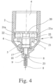
- Fig. 4 shows a second embodiment of the invention, in which the intermediate gear 16 is designed as a planetary gear.
- the planetary gear usually has a sun gear 20, a planetary gear carrier 21 and a ring gear 22.
- the fact that a planetary gear enables a particularly space-saving construction is already advantageous here.
- the illustration in Fig. 4 Furthermore, the planetary gears 21a, which are mounted on the planetary gear carrier 21, can be removed.
- one of the elements sun gear 20, planet gear carrier 21 and ring gear 22 is assigned to the drive motor 4, in particular to the drive shaft of the drive motor 4. Another of these elements is correspondingly assigned to the drive side of the feed gear 5. Finally, the third of these elements is braked or completely fixed at least for the auxiliary closing operation.
- the sun gear 20 is assigned to the drive motor 4, in particular to the drive shaft of the drive motor 4.
- the ring gear 22 is formed by the drive housing 2 and is fixed accordingly.
- the planetary gear carrier 21 is equipped with an internal thread and thus forms the spindle nut 7.
- the internal thread in the planetary gear carrier 21 is located specifically on the web plate of the planetary gear carrier 21. In principle, it can also be provided that the spindle nut 7 is coupled directly to the planetary gear carrier 21.
- FIG. 4 The embodiment shown again shows the basic principle of the feed gear 5 according to Fig. 3 realized.
- the rotation of the spindle nut 7 is converted into a longitudinal movement of the spindle 6.
- the spindle 6 is again provided with a nose 18 which runs in a longitudinal guide 17 to prevent rotation.
- the drive housing 2 has a single, continuous section. In principle, however, it is also conceivable that the drive housing 2 is composed of several sub-housings. For example, it may be advantageous to provide the ring gear 22 of the planetary gear 5 in a separate drive housing, in particular in order to be able to provide a correspondingly wear-resistant material for this purpose.
- a Bowden cable end piece 23 is supported on the drive housing 2. According to the invention, as shown in Fig. 4 shown, a longitudinal guide 17 of the anti-twisting device is provided on this Bowden cable end piece 23.
- the drive motor 4 is designed as an electric drive motor. In principle, however, it is also conceivable that this is a pneumatic or a hydraulic drive motor.
- the quick assembly of the Bowden cable 3 is particularly important.
- a type of Bowden cable quick release is provided.
- the Bowden core 8 is inserted into an opening in the spindle 6 or the spindle nut 7 and is clamped in place with a self-locking mechanism when pulled back.
- the electrical control of an auxiliary closing process is particularly simple in the embodiments shown.
- the electric drive motor 4 is energized in a first direction until the lock latch 10 has been moved into its overstroke position. After the drive motor 4 is switched off, the drive motor 4 is energized in the opposite direction until the spindle nut 7 or the spindle 6 reaches the starting position.
- the auxiliary closing drive in particular the drive motor 4 with optionally downstream intermediate gear 16 and further downstream feed gear 5, is not designed to be self-locking. This has the particular advantage that the arrangement can automatically fall back from the overstroke position into the main closing position after the drive motor 4 is switched off, namely due to the high door seal counterpressure then acting.
- At least the inside of the drive housing 2 is designed to be essentially rotationally symmetrical with respect to the longitudinal extension of the auxiliary closing drive. This also allows optimum utilization of the available installation space to be achieved.
- the drive housing 2 and the support of the Bowden cable casing 9, here the Bowden cable end piece 23, are configurable in such a way that different drive motors 4, different intermediate gears 16 and different feed gears 5, each with different dimensions, can be used. In certain applications, it may also be necessary to dispense with an intermediate gear 16.
- the drive housing 2 is designed in two parts to adapt to the respective drive motor 4 and/or the respective intermediate gear 16. It can also be advantageous for the drive housing 2 to be composed of more than two parts.
- the two parts 2a, 2b of the drive housing 2 are designed to be telescopic.
- the length of the drive housing 2 can be adapted to the selected components.
- a locking mechanism can be provided to fasten the two parts 2a, 2b of the drive housing 2 to one another.
- the in Fig. 5 The embodiment shown also shows that the Bowden cable end piece 23 is telescopic relative to the drive housing 2 in order to adapt to the respective feed gear 5.
- This can also only be provided as an alternative to the telescoping of the drive housing 2.
- the telescoping of the Bowden cable end piece 23 here means that the Bowden cable end piece 23 can be pushed onto the drive housing 2 in various positions.
- adaptation to the respective feed gear 5 is possible.
- a latch is preferably provided for fastening between the Bowden cable end piece 23 and the drive housing 2.
- the Bowden cable core 8 of the Bowden cable 3 is coupled to the spindle nut 7 off-center with respect to the axis of the spindle 6. Then it is further preferred that the spindle 6 is on the drive shaft of the drive motor 4 is also arranged off-center.
- a longitudinal guide 17 arranged parallel to the spindle 6 is provided to support the spindle nut 7, on which the spindle nut 7 runs.
- the longitudinal guide 17 can be a guide rod that runs through a corresponding guide hole in the spindle nut 7.
- a guide groove is also conceivable, into which the spindle nut 7 engages with a corresponding web-like shape.
- a second spindle 6a is provided which is coupled to the drive shaft of the drive motor 4 and that the spindle nut 7 has a second spindle nut thread which is assigned to this second spindle 6a. This is shown in Fig. 6 to be taken.
- the in Fig. 6 The embodiment shown in Figure 1 is similar to that shown in Fig. 5
- the embodiment shown has a drive motor 4, a downstream planetary gear 16 and a downstream spindle-spindle nut gear 5, which here has two spindles 6, 6a.
- the two spindles 6, 6a are coupled to the planetary gear carrier 21 of the planetary gear 16, in that the planetary gear carrier 21 has a spur gear that meshes with the spur gears of the two spindles 6, 6a.
- the two spindles 6, 6a rotate in opposite directions, so that the spindle threads must be oriented differently accordingly.
- the two spindles 6, 6a are arranged symmetrically with respect to the drive shaft of the drive motor 4. With such a symmetrical arrangement, the risk of the spindle nut 7 jamming on one of the two spindles 6, 6a is extremely low. This increases the overall operational reliability of the proposed auxiliary closing drive.
Landscapes
- Lock And Its Accessories (AREA)
- Power-Operated Mechanisms For Wings (AREA)
Description
- Die Erfindung betrifft einen Schließhilfsantrieb für ein Kraftfahrzeugschloß mit den Merkmalen des Oberbegriffs von Anspruch 1.
- Vorliegend sind unter dem Begriff Kraftfahrzeugschloß alle Arten von Tür-/Hauben-/Deckel- oder Klappenschlössern zusammengefaßt.
- Das Kraftfahrzeugschloß ist mit den üblichen Schließelementen Schloßfalle und Sperrklinke ausgestattet, wobei die Sperrklinke die Schloßfalle in einer Hauptschließstellung und in einer Vorschließstellung hält. Die Sperrklinke befindet sich dann in einer eingefallenen Stellung. Die Schloßfalle ist in haltenden Eingriff mit einem an der Karosserie befindlichen Schließkeil oder dergleichen bringbar. Vorliegend ist der Schließkeil oder dergleichen dem Kraftfahrzeugschloß zuzurechnen.
- Im Zuge der Erhöhung des Benutzungskomforts sind heutige Kraftfahrzeugschlösser mit unterschiedlichen automatischen Funktionen ausgestattet. Hierzu gehört beispielsweise eine Schließhilfsfunktion, bei der das Kraftfahrzeugschloß motorisch von einem Vorschließzustand in einen Hauptschließzustand überführt wird. Vorteilhaft ist hier die Tatsache, daß der Benutzer die Kraftfahrzeugtür zum Schließen nur bis zu einem Vorschließzustand verstellen muß, und daß dies mit vergleichsweise geringem Aufwand möglich ist. Türdichtungsgegendrücke sind hier noch nicht wirksam. Erst die Verstellung vom Vorschließzustand in den Hauptschließzustand ist mit einem Zusammendrücken der Türdichtung und damit mit einem erheblichen Kraftaufwand verbunden, was mittels eines Schließhilfsantriebs erfolgt.
- Es sind bereits verschiedene Varianten für die Realisierung der Schließhilfsfunktion bekannt. Eine Variante (
DE 39 35 804 C2 ) sieht vor, daß der mit der Schloßfalle zusammenwirkende Schließkeil für das Zuziehen der Kraftfahrzeugtür motorisch verlagerbar ist. Bei einer anderen Variante (DE 102 39 734 A1 ) ist es so, daß die Schloßfalle mittels der Schließhilfe motorisch von der Vorschließstellung in die Hauptschließstellung und damit das Kraftfahrzeugschloß insgesamt vom Vorschließzustand in den Hauptschließzustand verstellbar ist. - Bei der letztgenannten Realisierung der Schließhilfsfunktion wird der Schließhilfsantrieb dann aktiviert, wenn die Schloßfalle die Vorschließstellung erreicht. Hierfür ist eine Steuerungseinheit in Form einer Schließhilfssteuerung vorgesehen.
- Bei den obigen Anordnungen hat es sich als nachteilig herausgestellt, daß der Bauraumbedarf im Bereich des Kraftfahrzeugschlosses durch die Integration des Schließhilfsantriebs unerwünscht hoch ist, was zu erheblichen konstruktiven Beschränkungen führt. Ferner ist die Modularität der Anordnung im Hinblick auf die Realisierung der Zusatzfunktion "Schließhilfe" gering.
- Aus der
US 5,273,324 ist ein Schließhilfsantrieb bekannt, bei dem eine Spindel, an der ein Bowdenzug befestigt ist, von einem elektrischen Motor linear bewegt wird. Zwischen dem Motor und der Spindel ist ein Zahnradgetriebe vorgesehen. - Die
DE 31 46 804 A1 zeigt ein Betätigungselement für eine zentrale Türverriegelung von Kraftfahrzeugtüren, bei dem ein Elektromotor direkt eine Gewindespindel antreibt. Die Gewindespindel ist mit einem kleinen Steigungswinkel ausgerüstet. Auf der Gewindespindel ist eine in Führungsnuten drehfest geführte, axial verschiebbare Spindelmutter geführt. Durch Drehen der Gewindespindel ist ein Sperrteil in Ent- und Verriegelungsstellung bringbar. - Die
DE 103 20 660 A1 zeigt einen Stellantrieb, insbesondere für Zentralverriegelungen, bei dem in einem ersten Gehäuseteil eine Spindel mit einem an ihrer einen Seite angeordneten Antriebsrad drehbar gelagert ist. Das Antriebsrad steht mit einem Ritzel eines Elektromotors, dessen Längsachse parallel zur Längsachse der Spindel verläuft, in Eingriff. Die Spindel greift in einen Stößel ein, welcher mit einem zur Spindel komplementären Gewinde versehen ist. - Bei dem bekannten Schließhilfsantrieb (
DE 10 2006 048 026 A1 ), von dem die Erfindung ausgeht, ist der Schließhilfsantrieb separat vom Kraftfahrzeugschloß angeordnet und mit dem Kraftfahrzeugschloß über einen Bowdenzug antriebstechnisch gekoppelt. Dies löst die Bauraumproblematik im Bereich des Kraftfahrzeugschlosses in befriedigender Weise und entspricht einer modularen Bauweise. - Allerdings ist die Bauraumproblematik bei dem bekannten Schließhilfsantrieb lediglich verlagert worden. Die bekannten, derartig ausgestalteten Schließhilfsantriebe sind von beträchtlicher Größe, was zu entsprechenden Bauraumproblemen an der jeweiligen vom Kraftfahrzeugschloß entfernten Stelle führt. Ferner sind die bekannten Schließhilfsantriebe von beträchtlichem Gewicht.
- Der Erfindung liegt daher das Problem zugrunde, den bekannten Schließhilfsantrieb derart auszugestalten und weiterzubilden, daß der Bauraumbedarf sowie das Gewicht des Schließhilfsantriebs reduziert werden.
- Das obige Problem wird bei einem Schließhilfsantrieb durch die Merkmale von Anspruch 1 gelöst.
- Wesentlich ist zunächst die Erkenntnis, daß die Ausstattung des Schließhilfsantriebs mit einem Vorschubgetriebe zur Erzeugung einer linearen Antriebsbewegung, das als Spindel-Spindelmutter-Getriebe ausgestaltet ist, bei entsprechender Auslegung und das Vorsehen einer durch eine Nase gebildeten Verdrehsicherung, die in einer Längsführung läuft, zu einem minimalen Bauraumbedarf führt. Ferner läßt sich eine solche Anordnung mit einer minimalen Bauteilanzahl realisieren, was zusätzlich zu einem geringen Gewicht führt.
- Bei der besonders bevorzugten Ausgestaltung gemäß dem Anspruch 4 läßt sich der vorschlagsgemäße Schließhilfsantrieb auf einfache Weise auf den jeweiligen Anwendungsfall hin auslegen bzw. parametrieren. Unterschiedliche Anwendungsfälle können nämlich unterschiedliche Kräfte, Geschwindigkeiten und Vorschübe erfordern, was entsprechend zu unterschiedlichen Antriebsmotoren, Zwischengetrieben oder Vorschubgetrieben führt. Je nach Konfiguration muß das Antriebsgehäuse und ggf. das Bowdenzugendstück angepaßt werden.
- Im folgenden wird die Erfindung anhand einer lediglich Ausführungsbeispiele darstellenden Zeichnung näher erläutert. In der Zeichnung zeigt
- Fig. 1
- den strukturellen Aufbau eines vorschlagsgemäßen Schließhilfsantriebs im montierten Zustand,
- Fig. 2
- den Schließhilfsantrieb gemäß
Fig. 1 in einer nicht erfindungsgemäßen Ausführungsform, in einer geschnittenen Seitenansicht, - Fig. 3
- den Schließhilfsantrieb gemäß
Fig. 1 in einer ersten Ausfuhrungsform in einer geschnittenen Seitenansicht, - Fig. 4
- den Schließhilfsantrieb gemäß
Fig. 1 in einer zweiten Ausführungsform, in einer geschnittenen Seitenansicht, - Fig. 5
- den Schließhilfsantrieb gemäß
Fig. 4 mit teleskopierbarem Antriebsgehäuse und teleskopierbarem Bowdenzugendstück und - Fig. 6
- einen nicht erfindungsgemäßen Schließhilfsantrieb mit zwei Antriebsspindeln.
- Der in
Fig. 1 dargestellte, strukturelle Aufbau eines vorschlagsgemäßen Schließhilfsantriebs gilt für alle in denFig. 2 bis 4 dargestellten Ausführungsbeispiele. Dieser Schließhilfsantrieb ist einem Kraftfahrzeugschloß 1 zugeordnet. Hinsichtlich des weiten Verständnisses des Begriffs "Kraftfahrzeugschloß" darf auf den allgemeinen Teil der Beschreibung verwiesen werden. - Bei allen dargestellten Ausführungsformen weist der Schließhilfsantrieb ein eigenes Antriebsgehäuse 2 auf und ist im montierten Zustand separat vom Kraftfahrzeugschloß 1 angeordnet. Es läßt sich der Darstellung in
Fig. 1 entnehmen, daß der Schließhilfsantrieb über ein Übertragungsmittel 3 antriebstechnisch mit dem Kraftfahrzeugschloß 1 gekoppelt ist. - Im Detail läßt sich den
Fig. 2 bis 4 jeweils entnehmen, daß der Schließhilfsantrieb einen Antriebsmotor 4 aufweist, wobei im montierten Zustand mittels des Antriebsmotors 4 eine lineare Antriebsbewegung erzeugbar und über das Übertragungsmittel 3 auf das Kraftfahrzeugschloß 1 übertragbar ist. Durch diese lineare Antriebsbewegung läßt sich das Kraftfahrzeugschloß 1 von dem Vorschließzustand in den Hauptschließzustand überführen. Diese Zustände wurden im allgemeinen Teil der Beschreibung erläutert. - Die
Fig. 2 bis 4 zeigen in drei Ausführungsformen ferner, daß der Schließhilfsantrieb zur Erzeugung der linearen Antriebsbewegung ein dem Antriebmotor 4 nachgeschaltetes Vorschubgetriebe 5 aufweist und daß das Vorschubgetriebe 5 in allen Ausführungsformen als Spindel-Spindelmutter-Getriebe mit einer Spindel 6 und einer Spindelmutter 7 ausgestaltet ist. - Das Kraftfahrzeugschloß 1 kann weitgehend beliebigen Verschlußelementen in einem Kraftfahrzeugschloß zugeordnet sein. Vorzugsweise ist es allerdings so, daß das Kraftfahrzeugschloß 1 einer Kraftfahrzeugtür oder einer Kraftfahrzeugklappe zugeordnet ist. Bei der Kraftfahrzeugtür kann es sich auch um eine Schiebetür handeln.
- Das Übertragungsmittel 3 ist als Bowdenzug ausgestaltet, der eine Bowdenzugseele 8 und eine Bowdenzughülle 9 aufweist.
- Bei der Antriebsbewegung handelt es sich vorliegend um eine lineare Antriebsbewegung. Entsprechend ist die Verwendung eines Spindel-Spindelmutter-Getriebes für das Vorschubgetriebe 5 wesentlich. Je nach Ausgestaltung des Kraftfahrzeugschlosses 1 ist eine angepaßte Auslegung des Schließhilfsantriebs im Hinblick auf den Umfang der Antriebsbewegung und auf die Höhe der Antriebskraft notwendig.
- In allen Fällen ist es zunächst so, daß das Kraftfahrzeugschloß 1 die Schließelemente Schloßfalle 10 und Sperrklinke 11 sowie einen der Schloß falle 10 zugeordneten Schließkloben 12 aufweist. Das grundsätzliche Zusammenwirken dieser Komponenten wurde im allgemeinen Teil der Beschreibung erläutert.
- Bei der in
Fig. 1 dargestellten und insoweit bevorzugten Ausführungsform ist die Schloßfalle 10 in eine nicht dargestellte Vorschließstellung und in die dargestellte Hauptschließstellung bringbar. Hierfür weist die Schloßfalle 10 eine Vorrast 13 und eine Hauptrast 14 auf, die jeweils mit einem Eingriffsabschnitt 15 der Sperrklinke 11 in Eingriff bringbar sind. Bei der inFig. 1 dargestellten und insoweit bevorzugten Ausgestaltung ist es ferner so, daß der Schließhilfsantrieb im montierten Zustand mit der Schloßfalle 10 antriebstechnisch gekoppelt ist, und daß die Schloßfalle 10 durch die vom Schließhilfsantrieb erzeugte Antriebsbewegung von der Vorschließstellung in die Hauptschließstellung und damit das Kraftfahrzeugschloß 1 insgesamt von dem Vorschließzustand in den Hauptschließzustand bringbar ist. Dabei bewirkt der Schließhilfsantrieb vorzugsweise zunächst eine Verstellung der Schloßfalle 10 in eine Überhubstellung, so daß die Sperrklinke 11 einfallen kann. Anschließend fällt die Schloßfalle 10 zurück in die Hauptschließstellung und wird dort von der Sperrklinke 11 gehalten. Bei dieser Anordnung ist die Bowdenzugseele 8 des Bowdenzugs 3 vorzugsweise mit der Schloßfalle 10 gekoppelt. - Grundsätzlich ist es aber auch denkbar, daß der Schließhilfsantrieb nicht an der Schloßfalle 10, sondern am Schließkloben 12 angreift. Bei dieser nicht dargestellten Ausführungsform ist es vorgesehen, daß der Schließkloben 12 seinerseits in eine Vorschließstellung und in eine Hauptschließstellung bringbar ist, daß der Schließhilfsantrieb im montierten Zustand mit dem Schließkloben 12 antriebstechnisch gekoppelt ist und daß der Schließkloben 12 durch die vom Schließhilfsantrieb erzeugte Antriebsbewegung von der Vorschließstellung in die Hauptschließstellung und damit das Kraftfahrzeugsschloß 1 insgesamt von dem Vorschließzustand in den Hauptschließzustand bringbar ist.
- Beide Varianten von Kraftfahrzeugschlössern 1 erfordern die Übertragung einer Antriebsbewegung über das Übertragungsmittel 3, hier über den Bowdenzug 3. Allerdings ist der Bewegungsbereich sowie die benötigte Kraft je nach Ausführungsform unterschiedlich, was entsprechende Auswirkungen auf die Auslegung des Schließhilfsantriebs hat.
- Der Begriff "Spindel-Spindelmutter-Getriebe" sowie die Begriffe "Spindel" und "Spindelmutter" sind im Zusammenhang mit dem Vorschubgetriebe 5 weit zu verstehen. Grundsätzlich ist es dabei vorgesehen, daß die Spindel 6 ein Spindelgewinde aufweist und daß die Spindelmutter 7 ein Spindelmuttergewinde aufweist. Es kann aber auch vorgesehen sein, daß entweder die Spindel 6 oder die Spindelmutter 7 ein entsprechendes Gewinde aufweisen.
- Insbesondere kann es vorgesehen sein, daß die Spindel 6 einen Mitnehmer aufweist, der in das Spindelmuttergewinde der Spindelmutter 7 eingreift. Alternativ kann es auch vorgesehen sein, daß die Spindelmutter 7 einen Mitnehmer aufweist, der in das Spindelgewinde der Spindel 6 eingreift. Unter "Mitnehmer" ist hier jede Ausformung zu verstehen, die geeignet ist, in Eingriff mit einem Gewinde zu kommen und im Ergebnis einen Vorschub von Spindelmutter 7 oder Spindel 6 zu erzielen. Beispielsweise kann es sich bei dem Mitnehmer um eine einfache Nase oder dergleichen handeln.
- Im Zusammenhang mit den Gewinden von Spindel 6 und Spindelmutter 7 darf ferner darauf hingewiesen werden, daß sich die Steigung der Gewinde von Spindel 6 und/oder Spindelmutter 7 über deren Längserstreckung verändern kann. Damit läßt sich erreichen, daß sich die Übersetzung des Spindel-Spindelmutter-Getriebes, also des Vorschubgetriebes 5, über einen Schließhilfsvorgang verändert. Dies kann je nach konstruktiven Randbedingungen vorteilhaft sein.
-
Fig. 2 zeigt nun eine nicht erfindungsgemäße Anordnung, bei der die Spindel 6 der Antriebsseite und die Spindelmutter 7 der Abtriebsseite des Vorschubgetriebes 5 zugeordnet ist. Dies bedeutet, daß die Spindel 6 durch den Antriebsmotor 4 antreibbar ist und daß die Spindelmutter 7 den Abtrieb des Vorschubgetriebes 5 darstellt. Entsprechend ist es vorzugsweise vorgesehen, daß das Übertragungsmittel 3, hier die Bowdenzugseele 8 des Bowdenzugs 3, im montierten Zustand unmittelbar mit der Spindelmutter 7 gekoppelt ist. Hier und vorzugsweise ist es weiter so, daß die Spindelmutter 7 des Vorschubgetriebes 5 drehfest aber längsverschieblich angeordnet ist. Die Verdrehsicherung der Spindelmutter 7 wird im folgenden noch angesprochen. - Bei dem in
Fig. 2 dargestellten und insoweit nicht erfindungsgemäßen Ausführungsbeispiel ist dem Antriebsmotor 4 ein Zwischengetriebe 16 nachgeschaltet, das mit seiner Abtriebsseite auf die Spindel 6 wirkt. Grundsätzlich kann es aber auch vorgesehen sein, daß die nicht dargestellte Antriebswelle des Antriebsmotors 4 unmittelbar mit der Spindel 6 gekoppelt ist. In besonders bevorzugter Ausgestaltung bildet die Antriebswelle des Antriebsmotors 4 sogar selbst die Spindel 6. - Bei dem in
Fig. 2 dargestellten nicht erfindungsgemäßen Ausführungsbeispiel wird also die Spindel 6 angetrieben, während die Spindelmutter 7 drehfest aber längsverschieblich gelagert ist. Hier wird im Ergebnis eine Drehbewegung der Spindel 6 in eine Längsbewegung der Spindelmutter 7 umgewandelt. - Für die Verdrehsicherung ist eine Längsführung 17 vorgesehen, in die eine Nase 18 oder dergleichen der Spindelmutter 7 eingreift. Entsprechend bewegt sich bei einer Verdrehung der Spindel 6 die Spindelmutter 7 in
Fig. 2 nach oben bzw. nach unten.Fig. 2 zeigt die Ausgangslage der Spindelmutter 7. Die Endlage der Spindelmutter 7 nach Abschluß eines Schließhilfsvorgangs ist gestrichelt dargestellt. - Hier und vorzugsweise ist die Spindelmutter 7 als Hülse ausgestaltet, die an der in
Fig. 2 unteren Stirnseite verschlossen ist. Hier und vorzugsweise ist es weiter so, daß diese Stirnseite den Koppelpunkt 19 für das Übertragungsmittel 3, hier für die Bowdenzugseele 8 des Bowdenzugs 3, bereitstellt. - Um die Montage des Schließhilfsantriebs, insbesondere des Bowdenzugs 3, zu vereinfachen, ist es vorzugsweise vorgesehen, daß die Spindelmutter 7 zusammen mit dem Übertragungsmittel 3, hier mit der Bowdenzugseele 8 des Bowdenzugs 3, eine vormontierbare Einheit bildet. Insbesondere ist es vorgesehen, daß die Spindelmutter 7 im montierten Zustand untrennbar mit dem Übertragungsmittel 3, hier mit der Bowdenzugseele 8 des Bowdenzugs 3 verbunden ist. Denkbar ist, daß die Spindelmutter 7 im Kunststoff-Spritzverfahren hergestellt ist und daß die Bowdenzugseele 8 in die Spindelmutter 7 eingelassen ist. Andere Verbindungsvarianten können vorteilhaft anwendbar sein.
- Bei dem in
Fig. 2 dargestellten nicht erfindungsgemäßen Ausführungsbeispiel ist es so, daß der Antriebsmotor 4, das ggf. vorhandene Zwischengetriebe 16 und das Vorschubgetriebe 5 im Antriebsgehäuse 2 hintereinander angeordnet sind. Dabei ist es weiter vorzugsweise so, daß diese Komponenten auf die Antriebswelle des Antriebsmotors 4 und/oder auf die Achse der Spindel 6 ausgerichtet sind. - Eine andere Anordnung ist bei der ersten Ausführungsform der Erfindung gemäß
Fig. 3 gewählt worden. Dabei sind der Antriebsmotor 4 und das Vorschubgetriebe 5 im Antriebsgehäuse 2 bezogen auf die Längserstreckung des Schließhilfsantriebs zumindest zum Teil ineinander verschachtelt angeordnet. Diese verschachtelte Anordnung kann sich auch auf ein gegebenenfalls vorhandenes Zwischengetriebe 16 beziehen. - Hier und vorzugsweise ist die Spindelmutter 7 der Antriebsseite und die Spindel 6 der Abtriebsseite des Vorschubgetriebes 5 zugeordnet. Anders als bei der in
Fig. 1 dargestellten Ausführungsform wird hier also die Spindelmutter 7 durch den Antriebsmotor 4 angetrieben, während die Spindel 6 an der Spindelmutter 7 entlangläuft. Hier bildet die Spindel 6 den Abtrieb des Vorschubgetriebes 5 und ist entsprechend vorzugsweise unmittelbar mit dem Übertragungsmittel 3, hier der Bowdenzugseele 8 des Bowdenzugs 3, gekoppelt. - Dabei ist es weiter vorzugsweise vorgesehen, daß die Spindel 6 des Vorschubgetriebes 5 drehfest aber längsverschieblich angeordnet ist. Hier wird im Ergebnis eine Drehbewegung der Spindel 6 in eine Längsbewegung der Spindelmutter 7 umgewandelt.
- Das oben angesprochene Verschachteln der einzelnen Komponenten wird bei der in
Fig. 3 dargestellten Ausführungsform dadurch erreicht, daß die Antriebswelle des Antriebsmotors 4 als Hohlwelle ausgestaltet ist und daß die Hohlwelle die Spindelmutter 7 des Vorschubgetriebes 5 bildet und hierfür vorzugsweise ein Spindelmuttergewinde aufweist. Innerhalb der Spindelmutter 7 ist die Spindel 6 angeordnet, wobei die Verdrehsicherung wieder durch eine Art Nase 18, die in einer Längsführung 17 läuft, gebildet ist. - Es zeigt sich in
Fig. 3 anschaulich, daß der Bauraumbedarf insbesondere in Längserstreckung des Schließhilfsantriebs gesehen besonders gering ist. Dies wird insbesondere dadurch erreicht, daß der Antriebsmotor 4 im Hinblick auf den Antrieb der Hohlwelle nach Art eines elektrischen Direktantriebs ausgestaltet ist. Die Hohlwelle, hier die Spindelmutter 7, bildet also gleichzeitig den Rotor des Antriebsmotors. - Es läßt sich der Darstellung in
Fig. 3 ferner entnehmen, daß die Spindel 6 des Vorschubgetriebes 5 vollständig innerhalb der Spindelmutter 7 angeordnet ist. Hier und vorzugsweise gilt dies unabhängig davon, in welcher Stellung der Schließhilfsantrieb sich gerade befindet. - Interessant ist bei der in
Fig. 3 dargestellten und insoweit bevorzugten Ausführungsform die Tatsache, daß die Erstreckung des Antriebsmotors 4 insgesamt im wesentlichen der Erstreckung der Antriebswelle bzw. der Spindelmutter 7 entspricht. Dies ist in erster Linie darauf zurückzuführen, daß der Antriebsmotor 4 nach Art eines elektrischen Direktantriebs ausgestaltet ist. - Es wurde weiter oben schon angedeutet, daß zwischen den Antriebsmotor 4 und das Vorschubgetriebe 5 ein Zwischengetriebe 16 geschaltet sein kann. Dies ist in
Fig. 1 schematisch dargestellt. -
Fig. 4 zeigt eine zweite Ausführungsform der Erfindung, bei der das Zwischengetriebe 16 als Planetenradgetriebe ausgestaltet ist. Das Planetenradgetriebe weist regelmäßig ein Sonnenrad 20, einen Planetenradträger 21 und ein Hohlrad 22 auf. Vorteilhaft ist hierbei bereits die Tatsache, daß ein Planentenradgetriebe einen besonders platzsparenden Aufbau ermöglicht. Der Darstellung inFig. 4 sind ferner die Planetenräder 21a zu entnehmen, die am Planetenradträger 21 gelagert sind. - In besonders bevorzugter Ausgestaltung ist eines der Elemente Sonnenrad 20, Planetenradträger 21 und Hohlrad 22 dem Antriebsmotor 4, insbesondere der Antriebswelle des Antriebsmotors 4, zugeordnet. Ein anderes dieser Elemente ist entsprechend der Antriebsseite des Vorschubgetriebes 5 zugeordnet. Das dritte dieser Elemente schließlich ist zumindest für den Schließhilfsbetrieb gebremst oder komplett festgesetzt.
- Hier und vorzugsweise ist das Sonnenrad 20 dem Antriebsmotor 4, insbesondere der Antriebswelle des Antriebsmotors 4 zugeordnet. Das Hohlrad 22 wird vom Antriebsgehäuse 2 gebildet und ist entsprechend festgesetzt. Der Planetenradträger 21 ist mit einem Innengewinde ausgestattet und bildet somit die Spindelmutter 7. Das Innengewinde im Planetenträger 21 befindet sich im einzelnen an der Stegplatte des Planetenradträgers 21. Grundsätzlich kann es auch vorgesehen sein, daß die Spindelmutter 7 unmittelbar mit dem Planetenradträger 21 gekoppelt ist.
- Bei der in
Fig. 4 dargestellten Ausführungsform ist wieder das Grundprinzip des Vorschubgetriebes 5 gemäßFig. 3 realisiert. Die Drehung der Spindelmutter 7 wird in eine Längsbewegung der Spindel 6 umgewandelt. Hierfür ist es wieder vorgesehen, daß die Spindel 6 mit einer Nase 18 versehen ist, die zur Verdrehsicherung in einer Längsführung 17 läuft. - Bei allen dargestellten Ausführungsbeispielen weist das Antriebsgehäuse 2 einen einzigen, durchgehenden Abschnitt auf. Grundsätzlich ist es aber auch denkbar, daß sich das Antriebsgehäuse 2 aus mehreren Teilgehäusen zusammensetzt. Beispielsweise kann es vorteilhaft sein, das Hohlrad 22 des Planetenradgetriebes 5 in einem separaten Antriebsgehäuse vorzusehen, insbesondere um hierfür ein entsprechend verschleißfestes Material vorsehen zu können.
- Bei allen dargestellten Ausführungsformen ist es ferner so, daß sich ein Bowdenzugendstück 23 am Antriebsgehäuse 2 abstützt. Erfindungsgemäß ist, wie in
Fig. 4 dargestellt, eine Längsführung 17 der Verdrehsicherung an diesem Bowdenzugendstück 23 vorgesehen. - Bei allen dargestellten Ausführungsformen ist es schließlich so, daß der Antriebsmotor 4 als elektrischer Antriebsmotor ausgestaltet ist. Grundsätzlich ist es aber auch denkbar, daß es sich hierbei um einen pneumatischen oder um einen hydraulischen Antriebsmotor handelt.
- Besondere Bedeutung kommt der schnellen Montage des Bowdenzugs 3 zu. Eine Art Bowdenzugschnellverschluß ist vorgesehen. Die Bowdenseele 8 wird in eine Öffnung in der Spindel 6 bzw. der Spindelmutter 7 eingeführt und beim Zurückziehen mit Selbsthemmung festklemmt.
- Die elektrische Steuerung eines Schließhilfsvorgangs ist bei den dargestellten Ausführungsformen besonders einfach. Zum Starten eines Schließhilfsvorgangs wird der elektrische Antriebsmotor 4 in einer ersten Richtung bestromt, und zwar so lange, bis die Schloßfalle 10 in ihre Überhubstellung überführt worden ist. Nach dem Abschalten des Antriebsmotors 4 wird der Antriebsmotor 4 in entgegengesetzter Richtung bestromt, bis die Spindelmutter 7 bzw, die Spindel 6 die Ausgangsstellung erreicht.
- In besonders bevorzugter Ausgestaltung ist der Schließhilfsantrieb, insbesondere der Antriebsmotor 4 mitggf. nachgeschaltetem Zwischengetriebe 16 und weiter nachgeschaltetem Vorschubgetriebe 5, nicht selbsthemmend ausgestaltet. Dies hat insbesondere den Vorteil, daß die Anordnung von der Überhubstellung in die Hauptschließstellung nach Abschalten des Antriebsmotors 4 selbsttätig zurückfallen kann, und zwar durch den hohen dann wirkenden Türdichtungsgegendruck.
- In weiter bevorzugter Ausgestaltung ist es vorgesehen, daß zumindest die Innenseite des Antriebsgehäuses 2 im wesentlichen rotationssymmetrisch bezogen auf die Längserstreckung des Schließhilfsantriebs ausgestaltet ist. Auch hiermit läßt sich eine optimale Ausnutzung des zur Verfügung stehenden Bauraums erreichen.
- Es läßt sich zusammenfassen, daß mit allen dargestellten Ausführungsformen außerordentlich geringe Bauraumanforderungen verbunden sind. Durch die geringe Bauteilanzafil läßt sich ferner ein besonders geringes Gewicht erzielen. Im Ergebnis ist auch die Herstellung, insbesondere die Montage, mit besonders wenig Aufwand möglich.
- Es wurde im allgemeinen Teil erläutert, daß je nach Anwendungsfall eine unterschiedliche Auslegung des vorschlagsgemäßen Schließhilfsantriebs erforderlich ist. Um diese Auslegung mit minimalem Aufwand bewerkstelligen zu können, ist es bei dem in
Fig. 5 dargestellten und insoweit bevorzugten Ausführungsbeispiel vorgesehen, daß das Antriebsgehäuse 2 und die Abstützung der Bowdenzughülle 9, hier des Bowdenzugendstücks 23, derart konfigurierbar sind, daß unterschiedliche Antriebsmotoren 4, unterschiedliche Zwischengetriebe 16 und unterschiedliche Vorschubgetriebe 5, jeweils mit unterschiedlichen Abmessungen, einsetzbar sind. In bestimmten Anwendungsfällen kann es auch notwendig sein, auf ein Zwischengetriebe 16 zu verzichten. - Die obige Konfigurierbarkeit wird hier und vorzugsweise dadurch realisiert, daß das Antriebsgehäuse 2 zur Anpassung an den jeweiligen Antriebsmotor 4 und/oder das jeweilige Zwischengetriebe 16 zweiteilig ausgestaltet ist. Es kann auch vorteilhaft sein, daß sich das Antriebsgehäuse 2 aus mehr als zwei Teilen zusammensetzt.
- Im Sinne einer leichten Konfigurierbarkeit ist es nun vorzugsweise so, daß die beiden Teile 2a, 2b des Antriebsgehäuses 2 teleskopierbar ausgestaltet sind. Im einzelnen bedeutet dies, daß das erste Teil 2a des Antriebsgehäuses 2 über das zweite Teil 2b des Antriebsgehäuses 2 schiebbar ist. Durch die Überlappung der beiden Teile 2a, 2b des Antriebsgehäuses 2 ist die Länge des Antriebsgehäuses 2 auf die jeweils gewählten Komponenten anpaßbar. Zur Befestigung der beiden Teile 2a, 2 b des Antriebsgehäuses 2 aneinander kann eine Verrastung vorgesehen sein.
- Die in
Fig. 5 dargestellte Ausgestaltung zeigt auch, daß das Bowdenzugendstück 23 gegenüber dem Antriebsgehäuse 2 zur Anpassung auf das jeweilige Vorschubgetriebe 5 teleskopierbar ist. Dies kann auch nur alternativ zu der Teleskopierbarkeit des Antriebsgehäuses 2 vorgesehen sein. Die Teleskopierbarkeit des Bowdenzugendstücks 23 bedeutet hier, daß das Bowdenzugendstück 23 in verschiedenen Stellungen auf das Antriebsgehäuse 2 aufschiebbar ist. Je nach Überlappung zwischen dem Bowdenzugendstück 23 und dem Antriebsgehäuse 2 ist eine Anpassung an das jeweilige Vorschubgetriebe 5 möglich. Dies betrifft insbesondere die Auslegung des Schließhilfsantriebs auf unterschiedliche Betätigungshübe. Auch hier ist zur Befestigung zwischen dem Bowdenzugendstück 23 und dem Antriebsgehäuse 2 vorzugsweise eine Verrastung vorgesehen. - In nicht erfindungsgemäßen Anwendungsfällen kann es vorteilhaft sein, daß die Bowdenzugseele 8 des Bowdenzugs 3 bezogen auf die Achse der Spindel 6 außermittig mit der Spindelmutter 7 gekoppelt ist. Dann ist es weiter vorzugsweise so, daß die Spindel 6 bezogen auf die Antriebswelle des Antriebsmotors 4 ebenfalls außermittig angeordnet ist.
- Es liegt auf der Hand, daß bei der obigen, nicht erfindungsgemäßen außermittigen Anordnung die Gefahr des Verkantens der Spindelmutter 7 gegenüber der Spindel 6 gegeben ist. Für diesen Fall ist es vorzugsweise vorgesehen, daß zur Abstützung der Spindelmutter 7 eine parallel zu der Spindel 6 angeordnete Längsführung 17 vorgesehen ist auf der die Spindelmutter 7 läuft. Bei der Längsführung 17 kann es sich um eine Führungsstange handeln, die durch eine entsprechende Führungsbohrung in der Spindelmutter 7 hindurchläuft. Denkbar ist aber auch eine Führungsnut, in die die Spindelmutter 7 mit einer entsprechend stegartigen Ausformung eingreift.
- In einer nicht erfindungsgemäßen Ausgestaltung ist es allerdings vorgesehen, daß eine zweite mit der Antriebswelle des Antriebsmotors 4 gekoppelte Spindel 6a vorgesehen ist und daß die Spindelmutter 7 ein zweites Spindelmuttergewinde aufweist, das dieser zweiten Spindel 6a zugeordnet ist. Dies ist der Darstellung in
Fig. 6 zu entnehmen. - Die in
Fig. 6 dargestellte nicht erfindungsgemäße Ausführungsform weist ähnlich wie die inFig. 5 dargestellte Ausführungsform einen Antriebsmotor 4, ein nachgeschaltetes Planetenradgetriebe 16 und ein wiederum nachgeschaltetes Spindel-Spindelmutter-Getriebe 5 auf, das hier allerdings zwei Spindeln 6, 6a aufweist. Die beiden Spindeln 6, 6a sind mit dem Planetenradträger 21 des Planetenradgetriebes 16 gekoppelt, indem der Planetenradträger 21 ein Stirnrad aufweist, das mit den Stirnrädern der beiden Spindeln 6, 6a kämmt. Bei der inFig. 6 dargestellten und insoweit nicht erfindungsgemäßen Ausführungsform drehen die beiden Spindeln 6, 6a in entgegengesetzten Richtungen, so daß die Spindelgewinde entsprechend unterschiedlich orientiert sein müssen. - Hier und vorzugsweise sind die beiden Spindeln 6, 6a bezogen auf die Antriebswelle des Antriebsmotors 4 symmetrisch angeordnet. Bei einer solchen symmetrischen Anordnung ist die Gefahr des Verkantens der Spindelmutter 7 auf einer der beiden Spindeln 6, 6a äußerst gering. Dies erhöht insgesamt die Betriebssicherheit des vorschlagsgemäßen Schließhilfsantriebs.
Claims (4)
- Verwendung eines Schließhilfsantriebs für ein Kraftfahrzeugschloß (1), wobei der Schließhilfsantrieb ein eigenes Antriebsgehäuse (2) aufweist und im montierten Zustand separat vom Kraftfahrzeugschloß (1) angeordnet ist, wobei der Schließhilfsantrieb über ein Übertragungsmittel (3) antriebstechnisch mit dem Kraftfahrzeugschloß (1) gekoppelt ist, wobei der Schließhilfsantrieb einen elektrischen Antriebsmotor (4) aufweist, wobei im montierten Zustand mittels des Antriebsmotors (4) eine lineare Antriebsbewegung erzeugbar und über das Übertragungsmittel (3) auf das Kraftfahrzeugschloß (1) übertragbar ist, wobei das Kraftfahrzeugschloß (1) durch die Antriebsbewegung von einem Vorschließzustand in einen Hauptschließzustand überführbar ist, wobei der Schließhilfsantrieb zunächst eine Verstellung der Schloßfalle (10) in eine Überhubstellung bewirkt, so daß die Sperrklinke (11) einfallen kann und anschließend die Schloßfalle (10) zurück in die Hauptschließstellung fällt, wobei der Schließhilfsantrieb zur Erzeugung der Antriebsbewegung ein dem Antriebsmotor (4) nachgeschaltetes Vorschubgetriebe (5) aufweist und wobei das Vorschubgetriebe (5) als Spindel-Spindelmutter-Getriebe mit einer Spindel (6) und einer Spindelmutter (7) ausgestaltet ist,
dadurch gekennzeichnet,
dass die Spindel (6) eine Verdrehsicherung aufweist, welche durch eine Nase (18) gebildet wird, die in einer Längsführung (17) läuftdaß das Übertragungsmittel (3) als Bowdenzug mit Bowdenzugseele (8) und Bowdenzughülle (9) ausgestaltet ist, daß sich ein Bowdenzugendstück (23) am Antriebsgehäuse (2) abstützt und daß die Längsführung (17) der Verdrehsicherung am Bowdenzugendstück (23) vorgesehen ist, daß der elektrische Antriebsmotor zum Starten eines Schließhilfsvorgangs in einer ersten Richtung bestromt wird, und zwar so lange, bis die Schloßfalle (10) in ihre Überhubstellung überführt worden ist, und dass nach dem Abschalten des Antriebsmotors der Antriebsmotor in entgegengesetzter Richtung bestromt wird, bis die Spindel (6) die Ausgangsstellung erreicht, daß die Bowdenzugseele (8) in eine Öffnung in der Spindel (6) eingeführt und beim Zurückziehen mit Selbsthemmung festgeklemmt ist. - Verwendung nach Anspruch 1, dadurch gekennzeichnet, daß das Kraftfahrzeugschloß (1) die Schließelemente Schloßfalle (10) und Sperrklinke (11) sowie einen der Schloßfalle (10) zugeordneten Schließkloben (12) aufweist, vorzugsweise, daß die Schloßfalle (10) in eine Vorschließstellung und in eine Hauptschließstellung bringbar ist und dort jeweils von der Sperrklinke (11) gehalten wird, daß der Schließhilfsantrieb im montierten Zustand mit der Schloßfalle (10) antriebstechnisch gekoppelt ist und daß die Schloßfalle (10) durch die vom Schließhilfsantrieb erzeugte Antriebsbewegung von der Vorschließstellung in die Hauptschließstellung und damit das Kraftfahrzeugschloß (1) von dem Vorschließzustand in den Hauptschließzustand bringbar ist, oder, daß der Schließkloben (12) in eine Vorschließstellung und in eine Hauptschließstellung bringbar ist, daß der Schließhilfsantrieb im montierten Zustand mit dem Schließkloben (12) antriebstechnisch gekoppelt ist und daß der Schließkloben (12) durch die vom Schließhilfsantrieb erzeugte Antriebsbewegung von der Vorschließstellung in die Hauptschließstellung und damit das Kraftfahrzeugschloß (1) von dem Vorschließzustand in den Hauptschließzustand bringbar ist.
- Verwendung nach einem der vorhergehenden Ansprüche, dadurch gekennzeichnet, daß zwischen den Antriebsmotor (4) und das Vorschubgetriebe (5) ein Zwischengetriebe (16) geschaltet ist, vorzugsweise, daß das Zwischengetriebe (16) als Planetenradgetriebe ausgestaltet ist und daß das Planetenradgetriebe ein Sonnenrad (20), einen Planetenradträger (21) und ein Hohlrad (22) aufweist, vorzugsweise, daß eines der Elemente Sonnenrad (20), Planetenradträger (21) und Hohlrad (22) dem Antriebsmotor (4) zugeordnet ist, daß ein anderes der Elemente Sonnenrad (20), Planetenradträger (21) und Hohlrad (22) der Antriebsseite des Vorschubgetriebes (5) zugeordnet ist und daß das Dritte der Elemente Sonnenrad (20), Planetenradträger (21) und Hohlrad (22) zumindest für den Schließhilfsbetrieb gebremst oder festgesetzt ist, vorzugsweise, daß der Planetenradträger (21) der Antriebsseite des Vorschubgetriebes (5) zugeordnet ist, vorzugsweise, daß der Planetenradträger (21) die Spindelmutter (7) bildet oder unmittelbar mit der Spindelmutter (7) gekoppelt ist.
- Verwendung nach einem der vorhergehenden Ansprüche, dadurch gekennzeichnet, daß das Antriebsgehäuse (2) und ggf. die Abstützung der Bowdenzughülle (9), insbesondere eines Bowdenzugendstücks (23), derart konfigurierbar ist bzw. sind, daß unterschiedliche Antriebsmotoren (4) und/oder unterschiedliche - oder gar kein - Zwischengetriebe (16) und/oder unterschiedliche Vorschubgetriebe (5), jeweils mit unterschiedlichen Abmessungen, einsetzbar sind.
Applications Claiming Priority (2)
| Application Number | Priority Date | Filing Date | Title |
|---|---|---|---|
| DE202007016888 | 2007-12-03 | ||
| DE202008007719U DE202008007719U1 (de) | 2007-12-03 | 2008-06-10 | Schließhilfsantrieb für ein Kraftfahrzeugschloß |
Publications (4)
| Publication Number | Publication Date |
|---|---|
| EP2075395A2 EP2075395A2 (de) | 2009-07-01 |
| EP2075395A3 EP2075395A3 (de) | 2014-08-27 |
| EP2075395B1 EP2075395B1 (de) | 2019-02-20 |
| EP2075395B2 true EP2075395B2 (de) | 2024-10-30 |
Family
ID=40561123
Family Applications (1)
| Application Number | Title | Priority Date | Filing Date |
|---|---|---|---|
| EP08019787.4A Active EP2075395B2 (de) | 2007-12-03 | 2008-11-12 | Verwendung eines Schließhilfsantriebs für ein Kraftfahrzeugschloss |
Country Status (4)
| Country | Link |
|---|---|
| US (1) | US8528948B2 (de) |
| EP (1) | EP2075395B2 (de) |
| DE (1) | DE202008007719U1 (de) |
| HU (1) | HUE043955T2 (de) |
Families Citing this family (36)
| Publication number | Priority date | Publication date | Assignee | Title |
|---|---|---|---|---|
| DE202006014936U1 (de) * | 2006-09-28 | 2008-02-21 | Gebr. Bode Gmbh & Co. Kg | Antriebsvorrichtung für Ein- und Ausstiegseinrichtungen, insbesondere Fahrgasttüren, Einstiegsrampen, Schiebetritte u.dgl. an Fahrzeugen des öffentlichen Personenverkehrs |
| DE102009020498B4 (de) * | 2009-05-08 | 2015-08-27 | Binder Gmbh | Vorrichtung zum Öffnen einer Tür eines Klimaschranks, eines Brutschranks, einer Umweltsimulationskammer oder eines Tiefkühlgeräts oder dergleichen |
| DE202009016636U1 (de) | 2009-12-09 | 2011-04-21 | BROSE SCHLIEßSYSTEME GMBH & CO. KG | Kraftfahrzeugschloss |
| DE202010011541U1 (de) * | 2010-08-18 | 2011-11-23 | BROSE SCHLIEßSYSTEME GMBH & CO. KG | Antriebsanordnung |
| CN103080450B (zh) * | 2010-08-31 | 2016-07-06 | 开开特股份公司 | 用于机动车应用的执行单元 |
| WO2012028121A1 (de) * | 2010-08-31 | 2012-03-08 | Kiekert Aktiengesellschaft | Stelleinheit zur beaufschlagung von kraftfahrzeug-stellelementen |
| DE102010055530A1 (de) | 2010-12-22 | 2012-06-28 | BROSE SCHLIEßSYSTEME GMBH & CO. KG | Antrieb eines Kraftfahrzeugschlosses |
| US9187931B2 (en) * | 2011-09-01 | 2015-11-17 | Jamas Enterprises LLC | Sliding pin lock mechanism for overhead door |
| DE202012004789U1 (de) | 2012-05-15 | 2013-08-20 | BROSE SCHLIEßSYSTEME GMBH & CO. KG | Schließhilfsantrieb für ein Kraftfahrzeugschloss |
| DE102012218650A1 (de) * | 2012-10-12 | 2014-02-06 | Kiekert Ag | Stelleinheit für ein Kraftfahrzeugschloss nebst Herstellungsverfahren |
| DE102012024302A1 (de) * | 2012-12-12 | 2014-06-12 | Kiekert Aktiengesellschaft | Kraftfahrzeugtürschloss |
| DE102012025172A1 (de) | 2012-12-23 | 2014-06-26 | BROSE SCHLIEßSYSTEME GMBH & CO. KG | Schließsystemkomponente |
| WO2014169891A1 (de) * | 2013-04-17 | 2014-10-23 | Kiekert Aktiengesellschaft | Stelleinheit für einen kraftfahrzeugverschluss |
| DE102013206889B4 (de) | 2013-04-17 | 2022-10-27 | Kiekert Aktiengesellschaft | Stelleinheit für einen Kraftfahrzeugverschluss und Bowdenzug |
| DE202013004785U1 (de) | 2013-05-24 | 2014-08-27 | BROSE SCHLIEßSYSTEME GMBH & CO. KG | Antriebsanordnung zur motorischen Verstellung eines Verstellelements eines Kraftfahrzeugs |
| DE112014003306T5 (de) * | 2013-07-17 | 2016-05-12 | Magna Closures Inc. | Doppelmotorgerät mit Anwendung in Kraftanzieh- und Schlossmechanismus |
| DE102013018628A1 (de) | 2013-11-06 | 2015-05-07 | Brose Fahrzeugteile Gmbh & Co. Kommanditgesellschaft, Hallstadt | Einklemmschutz für eine verstellbare Fahrzeugtür |
| CN103556879B (zh) * | 2013-11-22 | 2015-12-02 | 韩飞 | 一种一体化电动锁头机构 |
| CN105386662B (zh) * | 2014-09-03 | 2020-05-08 | 麦格纳覆盖件有限公司 | 单级导螺杆系结致动器 |
| WO2016058718A1 (de) * | 2014-10-17 | 2016-04-21 | Euchner Gmbh + Co. Kg | Vorrichtung zur gesteuerten arretierung oder freigabe eines sicherheitsrelevanten, beweglichen bauteils |
| JP6455098B2 (ja) * | 2014-11-26 | 2019-01-23 | アイシン精機株式会社 | クローザ装置 |
| JP6394886B2 (ja) * | 2014-11-26 | 2018-09-26 | アイシン精機株式会社 | クローザ装置、車両用ドアロック装置 |
| DE202014106158U1 (de) | 2014-12-18 | 2016-03-21 | BROSE SCHLIEßSYSTEME GMBH & CO. KG | Schließhilfsantrieb für ein Kraftfahrzeugschloss |
| DE202014106279U1 (de) | 2014-12-26 | 2016-03-30 | BROSE SCHLIEßSYSTEME GMBH & CO. KG | Schließhilfsantrieb |
| DE202014106280U1 (de) | 2014-12-26 | 2016-03-30 | BROSE SCHLIEßSYSTEME GMBH & CO. KG | Schließhilfsantrieb |
| DE102015100750A1 (de) * | 2015-01-20 | 2016-07-21 | Kiekert Ag | Kraftfahrzeugschloss |
| DE102015004018A1 (de) | 2015-03-25 | 2016-09-29 | Kiekert Aktiengesellschaft | Zuziehantrieb für ein Kraftfahrzeugschloss |
| CA2994469C (en) | 2015-08-05 | 2024-01-02 | 9352-3033 Quebec Inc. | Cycle management system with locking mechanism |
| DE102016216686A1 (de) * | 2015-09-29 | 2017-03-30 | Magna Closures S.P.A. | Fahrzeugverriegelung mit Umlenkrolle für flexible Kabelführung |
| JP6641892B2 (ja) * | 2015-10-30 | 2020-02-05 | アイシン精機株式会社 | 車両用ドアクローザ |
| DE102018110608B4 (de) * | 2018-05-03 | 2025-07-03 | Kiekert Aktiengesellschaft | Kraftfahrzeug-Antriebsanordnung |
| US12331560B2 (en) * | 2019-06-17 | 2025-06-17 | Trimark Corporation | Motor control for powered closure with anti-pinch |
| DE102020124099A1 (de) * | 2020-09-16 | 2022-03-17 | Kiekert Aktiengesellschaft | Aufstellvorrichtung für ein Kraftfahrzeugtürelement |
| CN220565882U (zh) * | 2020-09-30 | 2024-03-08 | 深圳市凯迪仕智能科技股份有限公司 | 用于门锁的驱动机构、门锁 |
| DE102022100997B3 (de) * | 2022-01-17 | 2023-03-02 | Weber Gmbh & Co. Kg Kunststofftechnik Und Formenbau | Öffnungs- und Schließvorrichtung für ein Kraftfahrzeug |
| DE102022107518A1 (de) | 2022-03-30 | 2023-10-05 | Kiekert Aktiengesellschaft | Stellantrieb für kraftfahrzeug-technische Anwendungen |
Citations (5)
| Publication number | Priority date | Publication date | Assignee | Title |
|---|---|---|---|---|
| US6053064A (en) † | 1998-05-01 | 2000-04-25 | L & P Property Management Company | Lumbar support screw actuator |
| DE10105445A1 (de) † | 2000-10-13 | 2002-04-25 | Witte Velbert Gmbh & Co Kg | Drehfallenverschluss |
| WO2003050426A1 (en) † | 2001-12-07 | 2003-06-19 | L & P Property Management Company | Apparatus and method for travel multiplying actuator |
| WO2005078903A1 (en) † | 2004-02-06 | 2005-08-25 | L & P Property Management Company | In-line actuator apparatus and method |
| DE102006048206A1 (de) † | 2006-09-28 | 2008-04-17 | Qimonda Flash Gmbh | Speichersysteme und Verfahren zum Betreiben der Speichersysteme |
Family Cites Families (21)
| Publication number | Priority date | Publication date | Assignee | Title |
|---|---|---|---|---|
| US3154302A (en) * | 1962-01-08 | 1964-10-27 | Maruyama Kunimori | Automatic door opening and closing apparatus |
| DE3146804A1 (de) * | 1981-11-26 | 1983-06-01 | Fichtel & Sachs Ag, 8720 Schweinfurt | Betaetigungselement fuer eine zentralverriegelung an kraftfahrzeugtueren |
| US4691584A (en) * | 1985-02-20 | 1987-09-08 | Ohi Seisakusho Co., Ltd. | Actuator for remote devices or the like |
| DE3642915C2 (de) * | 1986-12-16 | 1994-08-04 | Vdo Schindling | Elektromotorisches Stellelement insbesondere für eine zentrale Türverriegelung |
| DE3935804A1 (de) * | 1989-10-27 | 1990-05-10 | Bocklenberg & Motte Bomoro | Kraftfahrzeug-haubenschloss oder -tuerschloss |
| JP2530516Y2 (ja) * | 1992-03-31 | 1997-03-26 | 株式会社大井製作所 | 自動車用ドアロックの閉鎖装置 |
| DE4334522C1 (de) * | 1993-10-09 | 1995-01-12 | Kiekert Gmbh Co Kg | Kraftfahrzeugtürverschluß, der von Hand oder über eine Zentralverriegelungseinrichtung zu bedienen ist sowie eine Diebstahlsicherungseinrichtung aufweist |
| JP3422632B2 (ja) * | 1996-04-05 | 2003-06-30 | 三菱重工業株式会社 | 電動アクチュエータの緩衝装置 |
| DE19935589A1 (de) * | 1999-08-02 | 2001-02-15 | Bosch Gmbh Robert | Kraftfahrzeug-Türschloß o. dgl. |
| US6536814B2 (en) * | 2000-03-08 | 2003-03-25 | Brose Schliessysteme Gmbh | Motor vehicle door lock with a controlled actuating element |
| US6550825B2 (en) * | 2000-06-06 | 2003-04-22 | Delphi Technologies, Inc. | Cinching door latch with planetary release mechanism |
| DE10239734A1 (de) * | 2002-08-26 | 2004-03-11 | Brose Schließsysteme GmbH & Co.KG | Kraftfahrzeug-Klappenschluß o. dgl. |
| DE10320660A1 (de) * | 2003-05-08 | 2004-12-09 | Siemens Ag | Stellantrieb |
| JP2006174690A (ja) * | 2004-11-18 | 2006-06-29 | Smc Corp | アクチュエータ制御システム |
| DE102006048026A1 (de) | 2005-11-08 | 2007-05-10 | BROSE SCHLIEßSYSTEME GMBH & CO. KG | Kraftfahrzeugschloßanordnung |
| KR101055971B1 (ko) * | 2005-12-07 | 2011-08-11 | 주식회사 만도 | 전기 주차브레이크 |
| DE202005019856U1 (de) * | 2005-12-16 | 2007-04-19 | BROSE SCHLIEßSYSTEME GMBH & CO. KG | Stellantrieb zur Betätigung von mindestens zwei Funktionselementen in einem Kraftfahrzeug |
| DE202006010697U1 (de) * | 2006-07-10 | 2007-11-22 | BROSE SCHLIEßSYSTEME GMBH & CO. KG | Antriebsanordnung zur motorischen Verstellung einer Kraftfahrzeugklappe oder -tür |
| US7575270B2 (en) * | 2007-10-26 | 2009-08-18 | Mitsuba Corporation | Opening/closing apparatus for vehicle |
| JP4962283B2 (ja) * | 2007-11-22 | 2012-06-27 | アイシン精機株式会社 | 車両ドア開閉装置 |
| DE102008009506A1 (de) * | 2008-02-15 | 2009-08-20 | Kiekert Ag | Kraftfahrzeugtürverschluss |
-
2008
- 2008-06-10 DE DE202008007719U patent/DE202008007719U1/de not_active Expired - Lifetime
- 2008-11-12 HU HUE08019787A patent/HUE043955T2/hu unknown
- 2008-11-12 EP EP08019787.4A patent/EP2075395B2/de active Active
- 2008-12-03 US US12/327,370 patent/US8528948B2/en active Active
Patent Citations (5)
| Publication number | Priority date | Publication date | Assignee | Title |
|---|---|---|---|---|
| US6053064A (en) † | 1998-05-01 | 2000-04-25 | L & P Property Management Company | Lumbar support screw actuator |
| DE10105445A1 (de) † | 2000-10-13 | 2002-04-25 | Witte Velbert Gmbh & Co Kg | Drehfallenverschluss |
| WO2003050426A1 (en) † | 2001-12-07 | 2003-06-19 | L & P Property Management Company | Apparatus and method for travel multiplying actuator |
| WO2005078903A1 (en) † | 2004-02-06 | 2005-08-25 | L & P Property Management Company | In-line actuator apparatus and method |
| DE102006048206A1 (de) † | 2006-09-28 | 2008-04-17 | Qimonda Flash Gmbh | Speichersysteme und Verfahren zum Betreiben der Speichersysteme |
Also Published As
| Publication number | Publication date |
|---|---|
| EP2075395A2 (de) | 2009-07-01 |
| HUE043955T2 (hu) | 2019-09-30 |
| DE202008007719U1 (de) | 2009-04-16 |
| US20090145182A1 (en) | 2009-06-11 |
| US8528948B2 (en) | 2013-09-10 |
| EP2075395A3 (de) | 2014-08-27 |
| EP2075395B1 (de) | 2019-02-20 |
Similar Documents
| Publication | Publication Date | Title |
|---|---|---|
| EP2075395B2 (de) | Verwendung eines Schließhilfsantriebs für ein Kraftfahrzeugschloss | |
| EP1780361B1 (de) | Antriebsanordnung zur motorischen Betätigung eines Funktionselements in einem Kraftfahrzeug | |
| EP1795685B1 (de) | Antriebsanordnung zur motorischen Verstellung einer Kraftfahrzeugtür o.dgl. | |
| EP3681750B1 (de) | Verschlussvorrichtung zum verschliessen einer durchgangsöffnung in einer fahrzeugkarosserie und fahrzeug mit einer solchen verschlussvorrichtung | |
| EP3037683B1 (de) | Schliesshilfsantrieb für ein kraftfahrzeugschloss | |
| DE19961975C1 (de) | Verriegelungsvorrichtung | |
| EP2423022B1 (de) | Verstellantrieb mit Notbetätigung | |
| EP3829956A1 (de) | Verstellantrieb für eine lenksäule und lenksäule für ein kraftfahrzeug | |
| EP3411549B1 (de) | Kraftfahrzeugtürschloss | |
| EP2345569B1 (de) | Schraubradgetriebe für eine Lenkung eines Kraftfahrzeugs | |
| EP2961902A2 (de) | Kraftfahrzeugtürverschluss | |
| DE102015107955A1 (de) | Elektrische Antriebseinheit | |
| EP1603213B1 (de) | Motorische Kraftfahrzeugkomponente | |
| DE102021213456A1 (de) | Spindelantrieb sowie Verfahren zum Betreiben eines solchen | |
| DE10135141A1 (de) | Starter | |
| EP3957813B1 (de) | Antriebsvorrichtung und schiebetür | |
| EP4158138B1 (de) | Antriebseinheit für kraftfahrzeug-technische anwendungen | |
| DE102020105637A1 (de) | Stellantrieb für kraftfahrzeugtechnische Anwendungen | |
| EP1431482A2 (de) | Kraftfahrzeug-Türschloss | |
| DE10301998A1 (de) | Schließhilfe zum Verschließen einer mit einem Türschloß versehenen Fahrzeugtür | |
| DE202021102062U1 (de) | Aktivierbare Antriebsvorrichtung | |
| EP4010555B1 (de) | Schiebetürantrieb für ein kraftfahrzeug | |
| DE102005048659B4 (de) | Verstellmechanismus | |
| DE3206760A1 (de) | Zentrale tuerblockiervorrichtung, insbesondere fuer die wagentueren von kraftfahrzeugen | |
| EP3033257B1 (de) | Verfahren und vorrichtung zur verriegelung einer schienenfahrzeugschiebetüre |
Legal Events
| Date | Code | Title | Description |
|---|---|---|---|
| PUAI | Public reference made under article 153(3) epc to a published international application that has entered the european phase |
Free format text: ORIGINAL CODE: 0009012 |
|
| AK | Designated contracting states |
Kind code of ref document: A2 Designated state(s): AT BE BG CH CY CZ DE DK EE ES FI FR GB GR HR HU IE IS IT LI LT LU LV MC MT NL NO PL PT RO SE SI SK TR |
|
| AX | Request for extension of the european patent |
Extension state: AL BA MK RS |
|
| PUAL | Search report despatched |
Free format text: ORIGINAL CODE: 0009013 |
|
| AK | Designated contracting states |
Kind code of ref document: A3 Designated state(s): AT BE BG CH CY CZ DE DK EE ES FI FR GB GR HR HU IE IS IT LI LT LU LV MC MT NL NO PL PT RO SE SI SK TR |
|
| AX | Request for extension of the european patent |
Extension state: AL BA MK RS |
|
| 17P | Request for examination filed |
Effective date: 20150227 |
|
| RBV | Designated contracting states (corrected) |
Designated state(s): AT BE BG CH CY CZ DE DK EE ES FI FR GB GR HR HU IE IS IT LI LT LU LV MC MT NL NO PL PT RO SE SI SK TR |
|
| AKX | Designation fees paid |
Designated state(s): AT BE BG CH CY CZ DE DK EE ES FI FR GB GR HR HU IE IS IT LI LT LU LV MC MT NL NO PL PT RO SE SI SK TR |
|
| AXX | Extension fees paid |
Extension state: MK Extension state: AL Extension state: RS Extension state: BA |
|
| 17Q | First examination report despatched |
Effective date: 20160428 |
|
| STAA | Information on the status of an ep patent application or granted ep patent |
Free format text: STATUS: EXAMINATION IS IN PROGRESS |
|
| REG | Reference to a national code |
Ref country code: DE Ref legal event code: R079 Ref document number: 502008016606 Country of ref document: DE Free format text: PREVIOUS MAIN CLASS: E05B0065120000 Ipc: E05B0047000000 |
|
| GRAP | Despatch of communication of intention to grant a patent |
Free format text: ORIGINAL CODE: EPIDOSNIGR1 |
|
| STAA | Information on the status of an ep patent application or granted ep patent |
Free format text: STATUS: GRANT OF PATENT IS INTENDED |
|
| RIC1 | Information provided on ipc code assigned before grant |
Ipc: E05B 81/38 20090701ALI20181012BHEP Ipc: E05B 47/00 20060101AFI20181012BHEP Ipc: E05B 79/20 20090701ALI20181012BHEP Ipc: E05B 53/00 20060101ALI20181012BHEP |
|
| INTG | Intention to grant announced |
Effective date: 20181116 |
|
| RIC1 | Information provided on ipc code assigned before grant |
Ipc: E05B 47/00 20060101AFI20181012BHEP Ipc: E05B 53/00 20060101ALI20181012BHEP Ipc: E05B 81/38 20140101ALI20181012BHEP Ipc: E05B 79/20 20140101ALI20181012BHEP |
|
| GRAS | Grant fee paid |
Free format text: ORIGINAL CODE: EPIDOSNIGR3 |
|
| GRAA | (expected) grant |
Free format text: ORIGINAL CODE: 0009210 |
|
| STAA | Information on the status of an ep patent application or granted ep patent |
Free format text: STATUS: THE PATENT HAS BEEN GRANTED |
|
| RIC1 | Information provided on ipc code assigned before grant |
Ipc: E05B 53/00 20060101ALI20181012BHEP Ipc: E05B 47/00 20060101AFI20181012BHEP Ipc: E05B 79/20 20140101ALI20181012BHEP Ipc: E05B 81/38 20140101ALI20181012BHEP |
|
| AK | Designated contracting states |
Kind code of ref document: B1 Designated state(s): AT BE BG CH CY CZ DE DK EE ES FI FR GB GR HR HU IE IS IT LI LT LU LV MC MT NL NO PL PT RO SE SI SK TR |
|
| REG | Reference to a national code |
Ref country code: GB Ref legal event code: FG4D Free format text: NOT ENGLISH |
|
| REG | Reference to a national code |
Ref country code: CH Ref legal event code: EP |
|
| REG | Reference to a national code |
Ref country code: DE Ref legal event code: R096 Ref document number: 502008016606 Country of ref document: DE |
|
| REG | Reference to a national code |
Ref country code: AT Ref legal event code: REF Ref document number: 1098378 Country of ref document: AT Kind code of ref document: T Effective date: 20190315 |
|
| REG | Reference to a national code |
Ref country code: IE Ref legal event code: FG4D Free format text: LANGUAGE OF EP DOCUMENT: GERMAN |
|
| REG | Reference to a national code |
Ref country code: LT Ref legal event code: MG4D |
|
| REG | Reference to a national code |
Ref country code: NL Ref legal event code: MP Effective date: 20190220 |
|
| PG25 | Lapsed in a contracting state [announced via postgrant information from national office to epo] |
Ref country code: PT Free format text: LAPSE BECAUSE OF FAILURE TO SUBMIT A TRANSLATION OF THE DESCRIPTION OR TO PAY THE FEE WITHIN THE PRESCRIBED TIME-LIMIT Effective date: 20190620 Ref country code: SE Free format text: LAPSE BECAUSE OF FAILURE TO SUBMIT A TRANSLATION OF THE DESCRIPTION OR TO PAY THE FEE WITHIN THE PRESCRIBED TIME-LIMIT Effective date: 20190220 Ref country code: LT Free format text: LAPSE BECAUSE OF FAILURE TO SUBMIT A TRANSLATION OF THE DESCRIPTION OR TO PAY THE FEE WITHIN THE PRESCRIBED TIME-LIMIT Effective date: 20190220 Ref country code: FI Free format text: LAPSE BECAUSE OF FAILURE TO SUBMIT A TRANSLATION OF THE DESCRIPTION OR TO PAY THE FEE WITHIN THE PRESCRIBED TIME-LIMIT Effective date: 20190220 Ref country code: NO Free format text: LAPSE BECAUSE OF FAILURE TO SUBMIT A TRANSLATION OF THE DESCRIPTION OR TO PAY THE FEE WITHIN THE PRESCRIBED TIME-LIMIT Effective date: 20190520 |
|
| PG25 | Lapsed in a contracting state [announced via postgrant information from national office to epo] |
Ref country code: IS Free format text: LAPSE BECAUSE OF FAILURE TO SUBMIT A TRANSLATION OF THE DESCRIPTION OR TO PAY THE FEE WITHIN THE PRESCRIBED TIME-LIMIT Effective date: 20190620 Ref country code: BG Free format text: LAPSE BECAUSE OF FAILURE TO SUBMIT A TRANSLATION OF THE DESCRIPTION OR TO PAY THE FEE WITHIN THE PRESCRIBED TIME-LIMIT Effective date: 20190520 Ref country code: LV Free format text: LAPSE BECAUSE OF FAILURE TO SUBMIT A TRANSLATION OF THE DESCRIPTION OR TO PAY THE FEE WITHIN THE PRESCRIBED TIME-LIMIT Effective date: 20190220 Ref country code: NL Free format text: LAPSE BECAUSE OF FAILURE TO SUBMIT A TRANSLATION OF THE DESCRIPTION OR TO PAY THE FEE WITHIN THE PRESCRIBED TIME-LIMIT Effective date: 20190220 Ref country code: GR Free format text: LAPSE BECAUSE OF FAILURE TO SUBMIT A TRANSLATION OF THE DESCRIPTION OR TO PAY THE FEE WITHIN THE PRESCRIBED TIME-LIMIT Effective date: 20190521 Ref country code: HR Free format text: LAPSE BECAUSE OF FAILURE TO SUBMIT A TRANSLATION OF THE DESCRIPTION OR TO PAY THE FEE WITHIN THE PRESCRIBED TIME-LIMIT Effective date: 20190220 |
|
| REG | Reference to a national code |
Ref country code: HU Ref legal event code: AG4A Ref document number: E043955 Country of ref document: HU |
|
| PG25 | Lapsed in a contracting state [announced via postgrant information from national office to epo] |
Ref country code: IT Free format text: LAPSE BECAUSE OF FAILURE TO SUBMIT A TRANSLATION OF THE DESCRIPTION OR TO PAY THE FEE WITHIN THE PRESCRIBED TIME-LIMIT Effective date: 20190220 Ref country code: SK Free format text: LAPSE BECAUSE OF FAILURE TO SUBMIT A TRANSLATION OF THE DESCRIPTION OR TO PAY THE FEE WITHIN THE PRESCRIBED TIME-LIMIT Effective date: 20190220 Ref country code: EE Free format text: LAPSE BECAUSE OF FAILURE TO SUBMIT A TRANSLATION OF THE DESCRIPTION OR TO PAY THE FEE WITHIN THE PRESCRIBED TIME-LIMIT Effective date: 20190220 Ref country code: DK Free format text: LAPSE BECAUSE OF FAILURE TO SUBMIT A TRANSLATION OF THE DESCRIPTION OR TO PAY THE FEE WITHIN THE PRESCRIBED TIME-LIMIT Effective date: 20190220 Ref country code: ES Free format text: LAPSE BECAUSE OF FAILURE TO SUBMIT A TRANSLATION OF THE DESCRIPTION OR TO PAY THE FEE WITHIN THE PRESCRIBED TIME-LIMIT Effective date: 20190220 Ref country code: RO Free format text: LAPSE BECAUSE OF FAILURE TO SUBMIT A TRANSLATION OF THE DESCRIPTION OR TO PAY THE FEE WITHIN THE PRESCRIBED TIME-LIMIT Effective date: 20190220 |
|
| REG | Reference to a national code |
Ref country code: DE Ref legal event code: R026 Ref document number: 502008016606 Country of ref document: DE |
|
| PLBI | Opposition filed |
Free format text: ORIGINAL CODE: 0009260 |
|
| PG25 | Lapsed in a contracting state [announced via postgrant information from national office to epo] |
Ref country code: PL Free format text: LAPSE BECAUSE OF FAILURE TO SUBMIT A TRANSLATION OF THE DESCRIPTION OR TO PAY THE FEE WITHIN THE PRESCRIBED TIME-LIMIT Effective date: 20190220 |
|
| PLAX | Notice of opposition and request to file observation + time limit sent |
Free format text: ORIGINAL CODE: EPIDOSNOBS2 |
|
| 26 | Opposition filed |
Opponent name: KIEKERT AKTIENGESELLSCHAFT Effective date: 20191119 |
|
| PG25 | Lapsed in a contracting state [announced via postgrant information from national office to epo] |
Ref country code: SI Free format text: LAPSE BECAUSE OF FAILURE TO SUBMIT A TRANSLATION OF THE DESCRIPTION OR TO PAY THE FEE WITHIN THE PRESCRIBED TIME-LIMIT Effective date: 20190220 |
|
| PG25 | Lapsed in a contracting state [announced via postgrant information from national office to epo] |
Ref country code: TR Free format text: LAPSE BECAUSE OF FAILURE TO SUBMIT A TRANSLATION OF THE DESCRIPTION OR TO PAY THE FEE WITHIN THE PRESCRIBED TIME-LIMIT Effective date: 20190220 |
|
| PLBB | Reply of patent proprietor to notice(s) of opposition received |
Free format text: ORIGINAL CODE: EPIDOSNOBS3 |
|
| REG | Reference to a national code |
Ref country code: CH Ref legal event code: PL |
|
| PG25 | Lapsed in a contracting state [announced via postgrant information from national office to epo] |
Ref country code: LI Free format text: LAPSE BECAUSE OF NON-PAYMENT OF DUE FEES Effective date: 20191130 Ref country code: CH Free format text: LAPSE BECAUSE OF NON-PAYMENT OF DUE FEES Effective date: 20191130 Ref country code: LU Free format text: LAPSE BECAUSE OF NON-PAYMENT OF DUE FEES Effective date: 20191112 Ref country code: MC Free format text: LAPSE BECAUSE OF FAILURE TO SUBMIT A TRANSLATION OF THE DESCRIPTION OR TO PAY THE FEE WITHIN THE PRESCRIBED TIME-LIMIT Effective date: 20190220 |
|
| REG | Reference to a national code |
Ref country code: BE Ref legal event code: MM Effective date: 20191130 |
|
| PG25 | Lapsed in a contracting state [announced via postgrant information from national office to epo] |
Ref country code: IE Free format text: LAPSE BECAUSE OF NON-PAYMENT OF DUE FEES Effective date: 20191112 |
|
| PG25 | Lapsed in a contracting state [announced via postgrant information from national office to epo] |
Ref country code: BE Free format text: LAPSE BECAUSE OF NON-PAYMENT OF DUE FEES Effective date: 20191130 |
|
| REG | Reference to a national code |
Ref country code: AT Ref legal event code: MM01 Ref document number: 1098378 Country of ref document: AT Kind code of ref document: T Effective date: 20191112 |
|
| PG25 | Lapsed in a contracting state [announced via postgrant information from national office to epo] |
Ref country code: AT Free format text: LAPSE BECAUSE OF NON-PAYMENT OF DUE FEES Effective date: 20191112 |
|
| PG25 | Lapsed in a contracting state [announced via postgrant information from national office to epo] |
Ref country code: CY Free format text: LAPSE BECAUSE OF FAILURE TO SUBMIT A TRANSLATION OF THE DESCRIPTION OR TO PAY THE FEE WITHIN THE PRESCRIBED TIME-LIMIT Effective date: 20190220 |
|
| PG25 | Lapsed in a contracting state [announced via postgrant information from national office to epo] |
Ref country code: MT Free format text: LAPSE BECAUSE OF FAILURE TO SUBMIT A TRANSLATION OF THE DESCRIPTION OR TO PAY THE FEE WITHIN THE PRESCRIBED TIME-LIMIT Effective date: 20190220 |
|
| APAH | Appeal reference modified |
Free format text: ORIGINAL CODE: EPIDOSCREFNO |
|
| APBM | Appeal reference recorded |
Free format text: ORIGINAL CODE: EPIDOSNREFNO |
|
| APBP | Date of receipt of notice of appeal recorded |
Free format text: ORIGINAL CODE: EPIDOSNNOA2O |
|
| APBQ | Date of receipt of statement of grounds of appeal recorded |
Free format text: ORIGINAL CODE: EPIDOSNNOA3O |
|
| APAH | Appeal reference modified |
Free format text: ORIGINAL CODE: EPIDOSCREFNO |
|
| P01 | Opt-out of the competence of the unified patent court (upc) registered |
Effective date: 20230816 |
|
| PGFP | Annual fee paid to national office [announced via postgrant information from national office to epo] |
Ref country code: DE Payment date: 20231130 Year of fee payment: 16 |
|
| APBU | Appeal procedure closed |
Free format text: ORIGINAL CODE: EPIDOSNNOA9O |
|
| PUAH | Patent maintained in amended form |
Free format text: ORIGINAL CODE: 0009272 |
|
| STAA | Information on the status of an ep patent application or granted ep patent |
Free format text: STATUS: PATENT MAINTAINED AS AMENDED |
|
| 27A | Patent maintained in amended form |
Effective date: 20241030 |
|
| AK | Designated contracting states |
Kind code of ref document: B2 Designated state(s): AT BE BG CH CY CZ DE DK EE ES FI FR GB GR HR HU IE IS IT LI LT LU LV MC MT NL NO PL PT RO SE SI SK TR |
|
| REG | Reference to a national code |
Ref country code: DE Ref legal event code: R102 Ref document number: 502008016606 Country of ref document: DE |
|
| PGFP | Annual fee paid to national office [announced via postgrant information from national office to epo] |
Ref country code: HU Payment date: 20241024 Year of fee payment: 17 |
|
| PGFP | Annual fee paid to national office [announced via postgrant information from national office to epo] |
Ref country code: GB Payment date: 20241001 Year of fee payment: 17 |
|
| PGFP | Annual fee paid to national office [announced via postgrant information from national office to epo] |
Ref country code: FR Payment date: 20241001 Year of fee payment: 17 |
|
| PGFP | Annual fee paid to national office [announced via postgrant information from national office to epo] |
Ref country code: CZ Payment date: 20241022 Year of fee payment: 17 |
|
| PG25 | Lapsed in a contracting state [announced via postgrant information from national office to epo] |
Ref country code: CZ Free format text: LAPSE BECAUSE OF FAILURE TO SUBMIT A TRANSLATION OF THE DESCRIPTION OR TO PAY THE FEE WITHIN THE PRESCRIBED TIME-LIMIT Effective date: 20190220 |
|
| REG | Reference to a national code |
Ref country code: DE Ref legal event code: R119 Ref document number: 502008016606 Country of ref document: DE |
|
| PG25 | Lapsed in a contracting state [announced via postgrant information from national office to epo] |
Ref country code: DE Free format text: LAPSE BECAUSE OF NON-PAYMENT OF DUE FEES Effective date: 20250603 |