EP2075134B1 - Dispositif d'enregistrement à jet d'encre - Google Patents
Dispositif d'enregistrement à jet d'encre Download PDFInfo
- Publication number
- EP2075134B1 EP2075134B1 EP08254112A EP08254112A EP2075134B1 EP 2075134 B1 EP2075134 B1 EP 2075134B1 EP 08254112 A EP08254112 A EP 08254112A EP 08254112 A EP08254112 A EP 08254112A EP 2075134 B1 EP2075134 B1 EP 2075134B1
- Authority
- EP
- European Patent Office
- Prior art keywords
- ink
- ink cartridge
- type
- cartridge
- discharging
- Prior art date
- Legal status (The legal status is an assumption and is not a legal conclusion. Google has not performed a legal analysis and makes no representation as to the accuracy of the status listed.)
- Active
Links
- 239000002699 waste material Substances 0.000 claims description 40
- 238000007599 discharging Methods 0.000 claims description 27
- 238000011010 flushing procedure Methods 0.000 claims description 20
- 238000010926 purge Methods 0.000 claims description 9
- 238000007641 inkjet printing Methods 0.000 claims description 6
- 239000006096 absorbing agent Substances 0.000 claims description 2
- 230000001419 dependent effect Effects 0.000 claims 2
- 239000000976 ink Substances 0.000 description 251
- 238000000034 method Methods 0.000 description 19
- 238000007639 printing Methods 0.000 description 17
- 238000010521 absorption reaction Methods 0.000 description 10
- 238000012423 maintenance Methods 0.000 description 7
- 239000000463 material Substances 0.000 description 7
- 239000000203 mixture Substances 0.000 description 4
- 229920002678 cellulose Polymers 0.000 description 3
- 239000001913 cellulose Substances 0.000 description 3
- 230000000881 depressing effect Effects 0.000 description 2
- 238000010586 diagram Methods 0.000 description 2
- 230000010365 information processing Effects 0.000 description 2
- 239000000049 pigment Substances 0.000 description 2
- 238000011084 recovery Methods 0.000 description 2
- 230000004044 response Effects 0.000 description 2
- 230000015271 coagulation Effects 0.000 description 1
- 238000005345 coagulation Methods 0.000 description 1
- 239000003086 colorant Substances 0.000 description 1
- 230000000694 effects Effects 0.000 description 1
- 230000006870 function Effects 0.000 description 1
- 239000002904 solvent Substances 0.000 description 1
- 239000000126 substance Substances 0.000 description 1
Images


Classifications
-
- B—PERFORMING OPERATIONS; TRANSPORTING
- B41—PRINTING; LINING MACHINES; TYPEWRITERS; STAMPS
- B41J—TYPEWRITERS; SELECTIVE PRINTING MECHANISMS, i.e. MECHANISMS PRINTING OTHERWISE THAN FROM A FORME; CORRECTION OF TYPOGRAPHICAL ERRORS
- B41J2/00—Typewriters or selective printing mechanisms characterised by the printing or marking process for which they are designed
- B41J2/005—Typewriters or selective printing mechanisms characterised by the printing or marking process for which they are designed characterised by bringing liquid or particles selectively into contact with a printing material
- B41J2/01—Ink jet
- B41J2/17—Ink jet characterised by ink handling
- B41J2/1721—Collecting waste ink; Collectors therefor
-
- B—PERFORMING OPERATIONS; TRANSPORTING
- B41—PRINTING; LINING MACHINES; TYPEWRITERS; STAMPS
- B41J—TYPEWRITERS; SELECTIVE PRINTING MECHANISMS, i.e. MECHANISMS PRINTING OTHERWISE THAN FROM A FORME; CORRECTION OF TYPOGRAPHICAL ERRORS
- B41J2/00—Typewriters or selective printing mechanisms characterised by the printing or marking process for which they are designed
- B41J2/005—Typewriters or selective printing mechanisms characterised by the printing or marking process for which they are designed characterised by bringing liquid or particles selectively into contact with a printing material
- B41J2/01—Ink jet
- B41J2/135—Nozzles
- B41J2/165—Prevention or detection of nozzle clogging, e.g. cleaning, capping or moistening for nozzles
- B41J2/16517—Cleaning of print head nozzles
- B41J2/1652—Cleaning of print head nozzles by driving a fluid through the nozzles to the outside thereof, e.g. by applying pressure to the inside or vacuum at the outside of the print head
-
- B—PERFORMING OPERATIONS; TRANSPORTING
- B41—PRINTING; LINING MACHINES; TYPEWRITERS; STAMPS
- B41J—TYPEWRITERS; SELECTIVE PRINTING MECHANISMS, i.e. MECHANISMS PRINTING OTHERWISE THAN FROM A FORME; CORRECTION OF TYPOGRAPHICAL ERRORS
- B41J2/00—Typewriters or selective printing mechanisms characterised by the printing or marking process for which they are designed
- B41J2/005—Typewriters or selective printing mechanisms characterised by the printing or marking process for which they are designed characterised by bringing liquid or particles selectively into contact with a printing material
- B41J2/01—Ink jet
- B41J2/17—Ink jet characterised by ink handling
- B41J2/175—Ink supply systems ; Circuit parts therefor
- B41J2/17503—Ink cartridges
- B41J2/17506—Refilling of the cartridge
- B41J2/17509—Whilst mounted in the printer
-
- B—PERFORMING OPERATIONS; TRANSPORTING
- B41—PRINTING; LINING MACHINES; TYPEWRITERS; STAMPS
- B41J—TYPEWRITERS; SELECTIVE PRINTING MECHANISMS, i.e. MECHANISMS PRINTING OTHERWISE THAN FROM A FORME; CORRECTION OF TYPOGRAPHICAL ERRORS
- B41J2/00—Typewriters or selective printing mechanisms characterised by the printing or marking process for which they are designed
- B41J2/005—Typewriters or selective printing mechanisms characterised by the printing or marking process for which they are designed characterised by bringing liquid or particles selectively into contact with a printing material
- B41J2/01—Ink jet
- B41J2/17—Ink jet characterised by ink handling
- B41J2/175—Ink supply systems ; Circuit parts therefor
- B41J2/17503—Ink cartridges
- B41J2/17543—Cartridge presence detection or type identification
- B41J2/17546—Cartridge presence detection or type identification electronically
Definitions
- the present invention relates to an inkjet recording device.
- a conventional jet recording device is supplied ink by mounting an ink cartridge in an ink cartridge receiving unit.
- the inkjet printing apparatus is designed to perform printing by using a predetermined suitable type of ink, e.g., a pigment ink, a dye ink, or the like, contained in the ink cartridge. If an ink cartridge containing an unsuitable ink is mounted, a risk of clogging may increase. Therefore, it is preferable to use the ink cartridge containing the predetermined type of ink.
- the known inkjet recording device when an unexpected ink cartridge is mounted, the known inkjet recording device discharges a large amount of ink in a maintenance operation, and this accelerates the ink discharge to a high speed.
- ink that is discharged by a maintenance operation is collected by a collection unit, e.g., a waste ink tank.
- a porous member e.g., a sponge
- waste ink is absorbed by the sponge.
- a total amount of waste ink is determined according to the type of the waste ink, on the basis of a discharge amount of waste ink per unit time, and a time for which waste ink should be discharged.
- Ink absorption ability, e.g., ink absorption rate, of the sponge is determined on the basis of these parameters.
- the waste ink may not be absorbed by the sponge and may overflow the waste ink tank into the recording device, which may damage a circuit board or other portion of the recording device.
- the discharge amount of waste ink per unit time can be increased to a value that is almost equal to the waste ink absorption rate of the sponge. Therefore, the discharge amount of waste ink per unit time can be set so that the time taken until completion of discharge of waste ink is made shortest, e.g., the discharge amount of waste ink per unit time is maximized, according to the waste ink absorption rate. Nevertheless, if a large amount of ink of an unsuitable ink cartridge, e.g., ink whose material properties are unsuitable is discharged, the discharge amount per unit time may exceed the maximum waste ink absorption rate, because a rate at which the ink having unsuitable material properties is absorbed by the sponge may not be assumed.
- EP 0 999 063 A2 discloses an inkjet printing apparatus according to the preamble of claim 1 comprising a capping position and pump unit for sucking ink from an installed ink cartridge in a maintenance operation.
- the amount of ink sucked from the ink cartridge can be varied according to ID data of the currently attached ink cartridge and the ID data of a previously attached ink cartridge. If the ID data of a currently attached ink cartridge is identical to the ID data of a previously attached ink cartridge then a normal suction amount is extracted from the ink cartridge.
- US 6,565,184 B1 discloses an ink jet printer configured to carry out a pre-discharge of ink on a newly mounted printing head. According to an embodiment, means are provided to eliminate the waste of ink in the head which is not newly mounted due to pre-discharge in an apparatus having a plurality of heads. This is achieved by making the time pre-discharge is performed on the newly mounted head different from that for the head which is not newly mounted.
- US 6,142,600 A discloses an ink jet printing method and an ink jet printer capable of printing high-quality images by the inkjet printing method even when ink is exchanged for ink having a different density, particularly ink having a lower density.
- a printer using this method identifies the type of an ink tank attached to a print head. When the printer detects in accordance with the type of an ink tank that an ink tank is changed to another ink tank containing ink with a different density, recovery conditions for the print head are changed in accordance with the type of the ink.
- US 2002/0167555 A1 discloses an ink jet printer configured such that printing head driving condition and various operation parameters associated with an ejection recovery operation are preliminarily set on the basis of the kind of ink recognized by an ink kind recognizing means.
- Fig. 1 is a perspective view showing an appearance of an inkjet recording device according to an embodiment of the invention.
- Fig. 2 is a block diagram relating to information processing of the inkjet recording device according to an embodiment of the invention.
- Fig. 3 is a flowchart of a process which is executed after replacement of an ink cartridge according to an embodiment of the invention.
- Fig. 4 shows the configuration of a portion of the inkjet recording device, relating to a flushing operation according to an embodiment of the invention.
- Fig. 5 shows the configuration of a portion of the inkjet recording device, relating to a purge operation according to another embodiment of the invention.
- Fig. 6 shows an example alarm message according to an embodiment of the invention.
- Fig. 1 is a perspective view showing an inkjet recording device 1 according to an embodiment of the invention.
- ink cartridges 70 may contain respective inks, and may be mounted in an ink supply unit 2.
- the ink supply unit 2 comprises a lid, and the ink cartridges 70 may be mounted into the ink supply unit 2 by opening the lid.
- Various manipulations for cartridge replacement, etc., may be performed using an operating panel 4, and various messages relating to a printing operation may be displayed on a display unit 5.
- Printing sheets may be supplied to a sheet tray 3.
- FIG. 2 is a block diagram relating to information processing of the inkjet recording device 1.
- a control unit 100 may comprise a CPU 101 which controls processing, a ROM 102 in which control programs may be stored, a RAM 103 where a program and data may be developed, and an Electrically Erasable Programmable Read-Only Memory("EEPROM") 104 which may be a nonvolatile memory.
- the control unit 100 thus may control the entire recording device 1.
- Commands that may be sent from the control unit 100 may be transmitted, via a bus 107, after being converted with an ASIC 130 into forms suitable for them, to circuits and boards, e.g., a head control board 33 for controlling an inkjet head 8, drive circuits 81 and 82 for driving motors, a scanner unit 86, the operating panel 4 for manipulating the inkjet recording device 1, a rotary encoder 83 for measuring a rotation speed of rollers, a linear encoder 84 to be used for moving a carriage 38 correctly, and ID reading units 51, e.g., an ink cartridge type detecting unit, e.g., a detecting unit, for reading identifications, e.g., IDs of IC chips, e.g., identification portions, such as memory chips, that may be mounted on the ink cartridges, respectively.
- a head control board 33 for controlling an inkjet head 8
- drive circuits 81 and 82 for driving motors
- a scanner unit 86 the operating panel 4 for manipul
- the CR motor 79 and the LF motor 80 may drive the carriage 38 and sheet feed rollers 20, on the basis of signals that are output from the drive circuits 81 and 82, respectively.
- Signals that may be output from the circuits and boards, such as the head control board 33, the drive circuits 81 and 82, the scanner unit 86, the operating panel 4, the rotary encoder 83, the linear encoder 84, and the ID reading unit 51, may be transmitted to the control unit 100 after being converted with the ASIC 130 into signals having timing that may be suitable for the bus 107.
- Fig. 4 outlines a configuration, relating to a printing operation using the inkjet head 8, and a maintenance operation of the inkjet recording device 1 according to an embodiment.
- a printing sheet P e.g., a printing medium
- ink droplets may be ejected from the nozzles of the inkjet head 8, in a printing operation.
- the printing sheet P is oriented horizontally.
- Ink tubes 60 may extend from the inkjet head 8 to respective ink cartridge receiving units 50.
- Ink cartridges 70 may be mounted in the respective ink cartridge receiving units 50 in a replaceable manner, and inks may be supplied from the ink cartridges 70 to the inkjet head 8 via the ink tubes 60.
- the ink cartridge receiving units 50 may be disposed inside the lid of the above-mentioned ink supply unit 2. As shown in Fig.
- the ink cartridges 70, the ink cartridge receiving units 50, and the ink tubes 60 may be provided in one or more of, e.g., four, systems, which may correspond to one or more of, e.g., four, respective colors, e.g., black, yellow, cyan, and magenta.
- the inkjet head 8 may transfer together with the carriage 38 in the horizontal direction, that is, perpendicularly to the transport direction of the sheet P.
- the movement direction of the carriage 38 may be restricted by a guide rail (not shown). This movement of the inkjet head 8 may enable printing on the entire surface of the sheet P.
- the movement of the inkjet head 8 and the ejecting of inks from the inkjet head 8 may be controlled by commands that are output from the control unit 100.
- the inkjet head 8 and the carriage 38 may be moved in the same manner, to outside the range of the sheet P, such that inkjet head 8 and carriage 38 may be located over a waste ink tank 40, e.g., an ink collection unit.
- a waste ink tank 40 e.g., an ink collection unit.
- an ink discharge may be performed by a flushing operation at the time of ink cartridge replacement.
- ink may be ejected toward the inside of the waste ink tank 40 from the inkjet head 8, which may be moved to over a discharge mouth 41 located at the top of the waste ink tank 40.
- a porous member 42 e.g., an absorber, made of sponge, felt, cellulose, or the like, may be disposed inside the waste ink tank 40. Since the porous member 42 may be disposed inside the waste ink tank 40, discharged ink may be absorbed by the porous member 42 and may be held stably.
- maintenance with ink discharge may be performed by a flushing operation when an ink cartridge 70 is replaced.
- ink solvent may volatilize, and dye or pigment may be deposited on the aperture surface, which may increases the ink viscosity.
- the flushing operation may be an operation of ejecting out ink of increased viscosity from the nozzles.
- the flushing operation may be performed regularly during printing operations, or when a lack of dots occurs during printing.
- an ordinary flushing operation may be performed in a state in which the inkjet head 8 has been moved to over the discharge mouth 41 of the waste ink tank 40.
- an ink discharge also may be performed by a flushing operation when an ink cartridge 70 is replaced, to avoid a mixing of different types of inks.
- Fig. 3 is a flowchart of a process which may be executed after replacement of an ink cartridge 70 according to an embodiment of the invention. The steps of the process may be executed in response to commands sent from the control unit 100.
- the inkjet recording device 1 may recognize a start of cartridge replacement work, e.g., detects opening of the lid of the ink supply unit 2 or recognizes removal of an ink cartridge 70.
- the inkjet recording device 1 may reset the remaining amount of ink.
- the control unit 100 may instruct the ID reading unit 51 to read an ID of a latest ink cartridge 70, e.g., to detect the type of the ink cartridge received by the ink cartridge receiving unit 50.
- the ID reading unit 51 reads electronic information, e.g., identifying information, such as an ID, that may be stored in an electronic information storing chip 71, e.g., a memory chip, of the ink cartridge 70.
- ID reading units 51 may be provided in respective ink cartridge receiving units 50.
- the reading of electronic information which may be performed at step S300 may be a process of obtaining binary information, which may indicate a type of the ink cartridge 70 mounted in the corresponding ink cartridge receiving unit 50.
- the binary information may indicate not only the type of the ink cartridge 70 but also " verifiable” or " unverifiable.” "Verifiable” may mean that electronic information may be read from the electronic information storing chip 71, and that read-out information may correspond to predetermined electronic information that may be specific to the printer type that was registered by the manufacturer.
- unverifiable may mean that electronic information may not be read from the electronic information storing chip 71, or that electronic information may be read out, but the read out electronic information may not correspond to the predetermined electronic information that may be specific to the printer type that was registered by the manufacturer.
- the predetermined electronic information that is specific to the printer type may be registered such that that the read-out information may not correspond to the predetermined electronic information when the electronic information may not be read from the electronic information storing chip 71.
- Another reason the cartridge may be "unverifiable," e.g., that electronic information may not be read from the electronic information storing chip 71, may be the case that no electronic information storing chip 71 is mounted on the ink cartridge 70.
- the control unit 100 may determine whether the ink cartridge 70 that has been mounted this time, e.g., the ink cartridge received by the ink cartridge receiving unit 50, or the ink cartridge detected by the detecting unit, is of the same type as the preceding ink cartridge 70. "Of the same type” may mean that both of the latest ink cartridge 70 and the preceding ink cartridge 70 have read out information that corresponds to the predetermined electronic information. On the other hand, “not of the same type” may mean that the read out information of at least one of the latest ink cartridge 70 and the preceding ink cartridge 70 may not correspond to the predetermined electronic information.
- control unit 100 may determine that the cartridges are "not of the same type,” even if the latest ink cartridge 70 and preceding ink cartridge 70 are the same type of "unverifiable” ink cartridge.
- Control unit 100 may store information of whether the read-out information of preceding ink cartridge 70 is "verifiable” or "unverifiable” because of a prior execution of step S510, which will be described herein. If the latest ink cartridge 70 is of the same type as the preceding one, e.g., "YES” at Step S400, the process may move to step S600. If the latest ink cartridge 70 is not of the same type as the preceding one, e.g., "NO” at Step S400, the process may move to step S410. At Step S600, a cartridge replacement discharge, which will be described in more detail herein, may be performed. Then, the execution of the process may be completed. A cartridge replacement strong discharge may be performed at step S410 and the following steps, which will be described in more detail herein.
- the cartridge replacement discharge and the cartridge replacement strong discharge will be described herein.
- the cartridge replacement discharge may be processing for, for example, discharging ink into, and ejecting air bubbles from, the ink tube 60 and the nozzles of the inkjet head 8, by performing a flushing operation as described above when a cartridge 70 is replaced.
- both of the preceding ink cartridge 70 and the latest ink cartridge 70 correspond to the predetermined electronic information, e.g., that it may be confirmed that the preceding ink and the latest ink may be the same ink, then the process may be at Step S600. Therefore, a mixing of different types of inks may not occur in the ink tube 60. Therefore, in the cartridge replacement discharge which may be performed at step S600, a smaller amount of ink may be discharged than in the cartridge replacement strong discharge, which will be described in more detail herein.
- the ink in the ink tube 60 may be of a different type than the ink in the latest ink cartridge 70, e.g., a state of mixing of different types of inks.
- the type of the "unverifiable ink" may be unknown, the two inks likely may be of different types.
- the ink that remained in the ink tube 60 when a cartridge 70 was replaced may come into contact with the ink in a latest ink cartridge 70. If the inks are brought into contact with each other, the inks may begin to diffuse into each other.
- the inks may coagulate inside the ink tube 60, which may disrupt a later printing operation. To avoid or reduce this phenomenon, it may be preferable to discharge the ink in the ink tube 60.
- the cartridge replacement strong discharge may be an operation that may completely replace at least the ink remaining in the ink tube 60 with the latest ink, to prevent or reduce ink coagulation due to mixing of different types of inks.
- the total amount of discharged ink may be set, for example, as 1 to 1.5 times larger than the capacity of the ink tube 60.
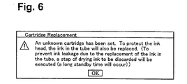
- an alarm message e.g., to the effect that a large amount of ink may be consumed, relating to the cartridge replacement strong discharge may be displayed.
- the user may indicate his or her intention of agreement, e.g., by depressing an OK button, or by depressing a button corresponding to an OK button on the operating panel 4, or by clicking on an OK button, or a button corresponding to the OK button that may be included in the alarm message displayed on a terminal that may be connected to the inkjet recording device 1.
- the display of the alarm message may allow the user to know that a cartridge replacement strong discharge is to be performed after the replacement with the latest ink cartridge 70.
- Fig. 6 shows an example alarm message. If the user's intention of agreement has been confirmed by, for example, depression of the OK button, at Step S510, information indicating whether the latest ink cartridge 70 corresponds to the predetermined electronic information or not, e.g., a type of latest ink cartridge 70, may be stored in the EEPROM 104. As described above, the information indicating whether the latest ink cartridge 70 corresponds to the predetermined electronic information may be used at the determining steps S400 and S520, e.g., as a type of previous ink cartridge 70, at the time of the next ink cartridge replacement.
- Step S520 it is determined whether the preceding ink previously corresponded to the predetermined electronic information If the preceding ink corresponded to the predetermined electronic information, e.g., "YES" at Step S520, the process may move to Step S530, e.g., a step of cartridge replacement strong high-speed discharge. If the preceding ink did not correspond to the predetermined electronic information, e.g., "NO” at Step S520, the process may move to Step S540, e.g., a step of cartridge replacement strong low-speed discharge. In this manner, the cartridge replacement strong discharge may be classified into two types, e.g., the cartridge replacement strong high-speed discharge, and the cartridge replacement strong low-speed discharge. These two types of cartridge replacement strong discharge will be described in more detail herein.
- the process may reach step S530, e.g., the step of cartridge replacement strong high-speed discharge, if the preceding ink cartridge 70 corresponded to the predetermined electronic information, and the latest ink cartridge 70 does not correspond to the predetermined electronic information, as seen from the determining results of steps S400 and S520. Therefore, the ink in the ink tube 60, which may be the ink of the preceding ink cartridge 70, may be predetermined ink.
- the process may reach Step S540, e.g., cartridge replacement strong low-speed discharge if the preceding ink cartridge 70 may not correspond to the predetermined electronic information, as seen from the judgment results of steps S400 and S520. Therefore, the ink in the ink tube 60 may not be the predetermined ink.
- the absorption rate may be determined by the combination of the material of the porous member 42 and the ink composition, if the ink type is known, the absorption rate may be set to such a value that may not cause an ink overflow from the waste ink tank 40. Nevertheless, if the preceding ink is unknown, then the absorption rate may not be able to be set. Furthermore, in the cartridge replacement strong discharge, the discharge amount may be larger than in an ordinary flushing operation, which may increase the importance of reducing the risk of ink overflow.
- Step S530 e.g., cartridge replacement strong high-speed discharge
- the term "high speed” may mean a highest speed in a range that may allow ink to be absorbed by the porous member 42.
- Fastest discharge rates in such a range that ink can be absorbed by the porous member 42, which may be employed at Step S530, may be determined in advance for respective known inks.
- the porous member 42 may be made of a material selected from a variety of materials, e.g., sponge, felt, cellulose, and the like.
- fastest discharge rates in such a range that ink that may be discharged at Step S530 may not overflow the waste ink tank 40, may be determined in advance, with respect to the types of materials which may be used as the porous member 42.
- fastest discharge rates may be determined in advance for combinations of known inks and types of materials of the porous member 42, in such a range that ink can be absorbed by the porous member 42.
- such fastest discharge rates may be stored in a memory, e.g., the ROM 102, and the like, and may employ, at Step S530, a discharge rate that may be equal to or lower than an applicable fastest discharge rate.
- Step S540 e.g., the cartridge replacement strong low-speed discharge
- flushing may be performed at a lower speed, such that ink may not overflow the waste ink tank 40.
- high-speed flushing may allow a maintenance operation to be performed without forcing the user to wait for a long time.
- low-speed flushing may allow a use of an apparatus in which it is important to avoid overflow of an unknown ink.
- the level of "low speed" of the cartridge replacement strong low-speed discharge may be varied according to different embodiments of the invention.
- the total flushing time may be set in advance, e.g., to 10 or 15 minutes, or the like.
- two low-speed levels may be set in advance, and the lower low-speed level may be employed before a command for the next print job may be received, and the higher low-speed level may be employed after a command for the next print job may be received. In this embodiment, it may be possible to flexibly accommodate the presence or absence of a print job.
- the high speed and the low speed of the cartridge replacement strong discharge may be realized by changing the ejecting interval of the flushing operation.
- the flushing operation may be such that a prescribed number of ink droplets are ejected emptily each time.
- the time interval between ejecting operations of a prescribed number of ink droplets may be set to be shorter in the case of the cartridge replacement strong high speed discharge, and may be set to be longer in the case of the cartridge replacement strong low-speed discharge.
- a corresponding process of an ordinary flushing operation e.g., a flushing operation not related to cartridge replacement, which may allow the system to be made simpler.
- Fig. 5 shows another embodiment of the invention. Only features which may differ from the previously described embodiment will be described herein.
- the purge operation may be a suction purge operation.
- the suction purge operation may be a maintenance operation in which ink is drawn out of the nozzles of the inkjet head 8, to remove air bubbles and foreign substances from the nozzles, or to discharge ink into the nozzles.
- the structure for the suction purge of this embodiment may be replaced by another structure, e.g., the structure for a known pressure purge.
- a purge mechanism may comprise a cap 45, a pump 46, a tube 47, and a waste ink tank 48, e.g., another example of an ink collection unit.
- the cap 45 may be brought into close contact with the inkjet head 8, and may draw ink using suction force generated by the pump 46. Drawn-out ink may be collected by the waste ink tank 48 through the tube 47.
- the cap 45 may be brought into close contact with the inkjet head 8 by an upward movement from a moving mechanism (not shown).
- a porous member made of sponge, felt, cellulose, or the like, may be disposed in the waste ink tank 48.
- Step S540 may be effective to prevent ink overflow in waste ink tank 48.
- the inkjet recording device may be an printer, a copier, a facsimile or a multi-functional device including printing function.
- the inkjet recording device may not limited to the recording device which forms an image on a sheet.
- the inkjet printer may be applied to form an image on various kinds of articles such as CD-ROM, clothes or 3-dimensinal bodies.
Landscapes
- Ink Jet (AREA)
Claims (15)
- Dispositif (1) d'enregistrement à jet d'encre comprenant :une unité (50) de réception de cartouche d'encre destinée à recevoir une cartouche d'encre (70) ;une tête à jet d'encre (8) configurée pour éjecter de l'encre ;un passage d'encre (60) configuré pour transporter l'encre de la cartouche d'encre (70) jusqu'à la tête à jet d'encre (8) ;une unité de détection (51) configurée pour détecter un type de la cartouche d'encre (70) reçue dans l'unité (50) de réception de cartouche d'encre ;une unité de déchargement (8, 33, 45-47) destinée à décharger de l'encre ;une unité (40, 48) de collecte d'encre usagée comprenant un absorbeur (42) configuré pour absorber l'encre déchargée ; etune unité de commande (100) configurée pour commander l'unité de déchargement (8, 33, 45-47) pour décharger une quantité de l'encre ;ladite unité de déchargement (8, 33, 45-47) est configurée pour exécuter, lorsqu'une première cartouche d'encre (70) présente dans ladite unité (50) de réception de cartouche d'encre est remplacée par une deuxième cartouche d'encre d'un type différent de celui de ladite première cartouche d'encre (70), une opération de déchargement intense de remplacement de cartouche comprenant le remplacement complet de l'encre restant dans le passage d'encre (60) de la première cartouche d'encre (70) avec l'encre de la deuxième cartouche d'encre (70) ; le dispositif d'enregistrement à jet d'encre est caractérisé en ce que :ladite unité de déchargement (8, 33, 45-47) est en outre configurée pour exécuter ladite opération de déchargement intense de remplacement de cartouche au choix à un débit parmi un premier débit de déchargement et un deuxième débit de déchargement, ledit premier débit de déchargement étant différent dudit deuxième débit de déchargement ; etl'unité de commande (100) est configurée pour commander l'unité de déchargement (8, 33, 45-47) afin de sélectionner l'un du premier débit de déchargement et du deuxième débit de déchargement sur la base du type de la cartouche d'encre (70) détecté par le unité de détection (51).
- Dispositif (1) d'enregistrement à jet d'encre selon la revendication 1, dans lequel la tête à jet d'encre (8) est configurée pour éjecter de l'encre vers l'un d'un support d'enregistrement et d'une unité (40, 48) de collecte d'encre usagée.
- Dispositif (1) d'enregistrement à jet d'encre selon la revendication 1 ou 2, dans lequel la quantité d'encre déchargée par l'unité de déchargement (8, 33, 45-47) dans ladite opération de déchargement intense de remplacement de cartouche est l'une parmi une première quantité de déchargement et une deuxième quantité de déchargement, et l'unité de commande (100) est en outre configurée pour commander l'unité de déchargement (8, 33, 45-47) afin de décharger l'une de la première quantité de déchargement et de la deuxième quantité de déchargement correspondant au type de la cartouche d'encre (70) détecté par l'unité de détection.
- Dispositif (1) d'enregistrement à jet d'encre selon la revendication 1, 2 ou 3, comprenant en outre une mémoire configurée pour stocker le type de cartouche d'encre (70) détecté par l'unité de détection (51), et pour stocker au moins un type précédent de cartouche d'encre précédemment détecté par l'unité de détection (51),
où l'unité de commande (100) est configurée pour comparer le type de la cartouche d'encre (70) stocké dans la mémoire, à l'au moins un type précédent de cartouche d'encre (70), où l'au moins un type précédent de cartouche d'encre (70) correspond à un type de la cartouche d'encre (70) la plus récemment montée sur l'unité (50) de réception de cartouche d'encre. - Dispositif (1) d'enregistrement à jet d'encre selon la revendication 4, dans lequel le type de cartouche d'encre (70) détecté par l'unité de détection (51) est l'un d'un premier type prédéterminé et d'un deuxième type prédéterminé où éventuellement le deuxième type prédéterminé correspond à un type non vérifiable de cartouche d'encre (70).
- Dispositif (1) d'enregistrement à jet d'encre selon la revendication 5 lorsque dépendante de la revendication 3, dans lequel, lorsque l'un du type de cartouche d'encre (70) détecté par l'unité de détection (51) est le deuxième type prédéterminé, et l'au moins un type précédent de cartouche d'encre (70) est le deuxième type prédéterminé, l'unité de commande (100) est configurée pour commander l'appareil de déchargement (8, 33, 45-47) afin de décharger la deuxième quantité de déchargement d'encre.
- Dispositif (1) d'enregistrement à jet d'encre selon la revendication 4, 5 ou 6, dans lequel la mémoire comprend une première partie de mémoire et une deuxième partie de mémoire, et le type de cartouche d'encre (70) détecté par l'unité de détection (51) est stocké dans la première partie de mémoire, et l'au moins un type précédent de cartouche d'encre (70) est stocké dans la deuxième partie de mémoire.
- Dispositif (1) d'enregistrement à jet d'encre selon l'une quelconque des revendications 4 à 7 lorsque dépendante de la revendication 3, dans lequel l'unité de commande (100) est configurée pour commander l'unité de déchargement (8, 33, 45-47) afin de décharger la deuxième quantité de déchargement d'encre, lorsqu'un résultat de la comparaison entre le type de la cartouche d'encre (70) et l'au moins un type précédent de cartouche d'encre (70) indique que le type de la cartouche d'encre (70) et l'au moins un type précédent de cartouche d'encre (70) sont différents où éventuellement la deuxième quantité de déchargement de l'encre est supérieure à une quantité d'encre restant dans le passage d'encre (60).
- Dispositif (1) d'enregistrement à jet d'encre selon l'une quelconque des revendications 4 à 8, dans lequel :l'unité de commande (100) est configurée pour commander l'unité de déchargement (8, 33, 45-47) afin de décharger l'encre dans le passage d'encre (60) au deuxième débit de déchargement lorsqu'au moins un type précédent de la cartouche d'encre (70) stocké dans la mémoire n'est pas un type prédéterminé, où le deuxième débit de déchargement est plus faible que le premier débit de déchargement.
- Dispositif (1) d'enregistrement à jet d'encre selon l'une des revendications précédentes, dans lequel l'unité de déchargement (8, 33, 45-47) est configurée pour décharger l'encre en exécutant l'une d'une opération de rinçage qui consiste à éjecter la quantité de l'encre de la tête à jet d'encre (8) vers l'unité (40) de collecte d'encre usagée et d'une opération de purge qui consiste à retirer la quantité d'encre de la tête à jet d'encre (8) jusqu'à l'unité (48) de collecte d'encre usagée.
- Dispositif (1) d'enregistrement à jet d'encre selon l'une des revendications précédentes, dans lequel l'unité de détection (51) est configurée pour lire des données stockées dans une puce mémoire reçues lorsque l'unité (50) de réception de cartouche d'encre reçoit la cartouche d'encre (70).
- Dispositif (1) d'enregistrement à jet d'encre selon l'une des revendications précédentes, dans lequel l'unité de commande (100) est configurée pour déterminer un type de l'encre correspondant au type de la cartouche d'encre (70) détecté par l'unité de détection (51).
- Dispositif (1) d'enregistrement à jet d'encre selon l'une quelconque des revendications 4 à 12, dans lequel :l'unité de commande (100) est configurée pour déterminer un type de l'encre correspondant au type de la cartouche d'encre (70) détecté par l'unité de détection (51), etl'unité de commande (100) est configurée pour déterminer que le type d'encre correspondant au type de la cartouche d'encre (70) se mélange avec un type d'encre différent correspondant à l'au moins une cartouche d'encre (70) précédente, lorsque qu'un résultat de la comparaison entre le type de la cartouche d'encre (70) et l'au moins un type précédent de cartouche d'encre (70) indique que le type de la cartouche d'encre (70) et l'au moins un type précédent de cartouche d'encre (70) sont différents.
- Système d'impression à jet d'encre comprenant :une cartouche d'encre (70) configurée pour stocker de l'encre et comprenant une partie d'identification (71) ; etun Dispositif (1) d'enregistrement à jet d'encre selon l'une des revendications précédentes, dans lequel l'unité (50) de réception de cartouche d'encre est configurée pour recevoir la cartouche d'encre (70) et la tête à jet d'encre (8) est configurée pour éjecter l'encre.
- Système d'impression à jet d'encre selon la revendication 14, dans lequel la partie d'identification (71) comprend une puce mémoire, et l'unité de détection (51) est configurée pour détecter le type de la cartouche d'encre (70) en lisant des données stockées dans la puce mémoire (71) et/ou dans lequel la cartouche d'encre (70) est configurée pour stocker un type particulier d'encre, et l'unité de commande (100) est configurée pour déterminer le type particulier d'encre en déterminant le type de la cartouche d'encre (70) détecté par l'unité de détection (51).
Applications Claiming Priority (1)
| Application Number | Priority Date | Filing Date | Title |
|---|---|---|---|
| JP2007340693A JP4721068B2 (ja) | 2007-12-28 | 2007-12-28 | インクジェット記録装置 |
Publications (3)
| Publication Number | Publication Date |
|---|---|
| EP2075134A2 EP2075134A2 (fr) | 2009-07-01 |
| EP2075134A3 EP2075134A3 (fr) | 2009-12-30 |
| EP2075134B1 true EP2075134B1 (fr) | 2011-06-29 |
Family
ID=40514108
Family Applications (1)
| Application Number | Title | Priority Date | Filing Date |
|---|---|---|---|
| EP08254112A Active EP2075134B1 (fr) | 2007-12-28 | 2008-12-22 | Dispositif d'enregistrement à jet d'encre |
Country Status (4)
| Country | Link |
|---|---|
| US (1) | US8328322B2 (fr) |
| EP (1) | EP2075134B1 (fr) |
| JP (1) | JP4721068B2 (fr) |
| CN (1) | CN101468550B (fr) |
Families Citing this family (12)
| Publication number | Priority date | Publication date | Assignee | Title |
|---|---|---|---|---|
| US8456705B2 (en) * | 2009-08-07 | 2013-06-04 | International Paper Company | System, method and software for reducing printer colorant usage |
| JP5304671B2 (ja) * | 2010-01-29 | 2013-10-02 | ブラザー工業株式会社 | カートリッジ装着ユニット |
| JP5644248B2 (ja) * | 2010-08-11 | 2014-12-24 | セイコーエプソン株式会社 | 液滴吐出装置 |
| JP5991113B2 (ja) * | 2012-09-25 | 2016-09-14 | ブラザー工業株式会社 | インクジェット記録装置 |
| JP5874719B2 (ja) * | 2013-12-19 | 2016-03-02 | ブラザー工業株式会社 | インクジェット記録装置 |
| WO2015146494A1 (fr) * | 2014-03-28 | 2015-10-01 | クオリカプス株式会社 | Dispositif et procédé de nettoyage de tête à jet d'encre |
| CN104325792A (zh) * | 2014-11-03 | 2015-02-04 | 合肥万合科技信息服务有限公司 | 一种喷墨打印机用废墨收集装置 |
| JP6465468B2 (ja) * | 2015-04-23 | 2019-02-06 | ヒューレット−パッカード デベロップメント カンパニー エル.ピー.Hewlett‐Packard Development Company, L.P. | 印刷材料カートリッジ |
| WO2016171694A1 (fr) * | 2015-04-23 | 2016-10-27 | Hewlett-Packard Development Company, L.P. | Cartouche de matériau d'impression |
| JP6663667B2 (ja) | 2015-09-09 | 2020-03-13 | 株式会社日立産機システム | インクジェット記録装置及びインクジェット記録装置のインク情報表示方法 |
| JP6897152B2 (ja) * | 2017-02-27 | 2021-06-30 | セイコーエプソン株式会社 | 液体噴射装置 |
| JP2018154006A (ja) * | 2017-03-17 | 2018-10-04 | セイコーエプソン株式会社 | 印刷制御装置、印刷装置、印刷制御方法 |
Family Cites Families (16)
| Publication number | Priority date | Publication date | Assignee | Title |
|---|---|---|---|---|
| JP2962838B2 (ja) | 1991-01-18 | 1999-10-12 | キヤノン株式会社 | インクジェット記録装置 |
| JP3233175B2 (ja) * | 1993-03-11 | 2001-11-26 | セイコーエプソン株式会社 | インクジェット式記録装置 |
| JP3406348B2 (ja) | 1993-05-31 | 2003-05-12 | 株式会社リコー | インクジェット記録装置用廃インクタンク |
| US5988782A (en) | 1995-04-07 | 1999-11-23 | Canon Kabushiki Kaisha | Ink-jet printing apparatus |
| DE69635869T2 (de) | 1995-12-25 | 2006-10-26 | Seiko Epson Corp. | Tintenstrahlaufzeichnungsapparat für tintenpatrone |
| JP3413052B2 (ja) | 1996-04-23 | 2003-06-03 | キヤノン株式会社 | インクジェット記録装置及び制御方法 |
| DE69723481T2 (de) * | 1996-11-11 | 2003-12-24 | Seiko Epson Corp., Tokio/Tokyo | Tintenstrahlaufzeichnungsgerät |
| JPH10181046A (ja) | 1996-11-11 | 1998-07-07 | Seiko Epson Corp | インクジェット式記録装置 |
| JP3664218B2 (ja) * | 1998-05-25 | 2005-06-22 | セイコーエプソン株式会社 | インクジェット記録装置、及びインクカートリッジ |
| JP2000198220A (ja) * | 1998-11-05 | 2000-07-18 | Seiko Epson Corp | インクジェット記録装置、及びインクカ―トリッジ |
| JP2004074590A (ja) * | 2002-08-19 | 2004-03-11 | Konica Minolta Holdings Inc | インクジェット記録装置 |
| JP4574205B2 (ja) * | 2004-03-31 | 2010-11-04 | キヤノン株式会社 | 記録装置 |
| JP2006192732A (ja) * | 2005-01-14 | 2006-07-27 | Canon Inc | インクジェット記録装置 |
| JP2007118339A (ja) * | 2005-10-27 | 2007-05-17 | Seiko Epson Corp | インクジェットプリンタ、インクジェットプリンタの機能回復制御方法およびプログラム |
| JP2007223266A (ja) | 2006-02-27 | 2007-09-06 | Seiko Epson Corp | 液体噴射装置およびそのクリーニング方法 |
| JP4328982B2 (ja) | 2007-02-28 | 2009-09-09 | ブラザー工業株式会社 | インクジェット記録装置 |
-
2007
- 2007-12-28 JP JP2007340693A patent/JP4721068B2/ja active Active
-
2008
- 2008-10-17 CN CN2008101499609A patent/CN101468550B/zh active Active
- 2008-12-22 US US12/342,057 patent/US8328322B2/en active Active
- 2008-12-22 EP EP08254112A patent/EP2075134B1/fr active Active
Also Published As
| Publication number | Publication date |
|---|---|
| US8328322B2 (en) | 2012-12-11 |
| JP2009160781A (ja) | 2009-07-23 |
| CN101468550A (zh) | 2009-07-01 |
| EP2075134A3 (fr) | 2009-12-30 |
| JP4721068B2 (ja) | 2011-07-13 |
| US20090167796A1 (en) | 2009-07-02 |
| CN101468550B (zh) | 2012-02-01 |
| EP2075134A2 (fr) | 2009-07-01 |
Similar Documents
| Publication | Publication Date | Title |
|---|---|---|
| EP2075134B1 (fr) | Dispositif d'enregistrement à jet d'encre | |
| US7648224B2 (en) | Inkjet recording apparatus | |
| JP4328982B2 (ja) | インクジェット記録装置 | |
| US6994416B2 (en) | Inkjet recording apparatus for controlling recovery operation by managing cap-open state and recovery control method | |
| US20060268050A1 (en) | Nozzle face-cleaning method | |
| JP2009166479A (ja) | 印刷装置および印刷装置の制御方法 | |
| US6352333B2 (en) | Method and apparatus for preventing nozzle clogging in ink jet printing apparatus | |
| JP2000158673A (ja) | インクジェット式記録装置および同装置に用いられるフラッシング制御方法並びに制御装置 | |
| JP5304548B2 (ja) | 液体吐出装置 | |
| WO2002014074A1 (fr) | Imprimante a jet d'encre et procede de nettoyage du systeme de restauration | |
| JPH10272787A (ja) | インクジェット記録装置 | |
| JP2002052740A (ja) | インクジェット記録装置およびその回復系清掃方法 | |
| US20030058300A1 (en) | Ink jet recovery system having variable recovery | |
| JP2003019816A (ja) | 印字装置 | |
| US10696052B1 (en) | Submersion cap devices stabilizing ink in nozzles of inkjet printheads | |
| JP2002187293A (ja) | インクジェット式記録装置及びインク滴の吐出検査方法 | |
| JP4878077B2 (ja) | インクジェット記録装置 | |
| JP2001105583A (ja) | インクジェット式記録装置 | |
| JP3610575B2 (ja) | インクジェットプリンタ | |
| JP2002283659A (ja) | 記録装置及び動作実行モードの設定制御方法 | |
| JPH08238781A (ja) | 記録装置及び記録装置を用いる電子機器、及び該装置における交換制御方法 | |
| JP3823445B2 (ja) | インクジェット記録装置及びインクカートリッジ交換方法 | |
| JP2011167954A (ja) | 液体吐出ヘッドのノズルチェック方法および液体吐出装置、ならびにインクジェットプリンター | |
| JP4078730B2 (ja) | ポータブルプリンタ | |
| JP6929619B2 (ja) | インクジェット記録装置及びクリーニング方法 |
Legal Events
| Date | Code | Title | Description |
|---|---|---|---|
| PUAI | Public reference made under article 153(3) epc to a published international application that has entered the european phase |
Free format text: ORIGINAL CODE: 0009012 |
|
| AK | Designated contracting states |
Kind code of ref document: A2 Designated state(s): AT BE BG CH CY CZ DE DK EE ES FI FR GB GR HR HU IE IS IT LI LT LU LV MC MT NL NO PL PT RO SE SI SK TR |
|
| AX | Request for extension of the european patent |
Extension state: AL BA MK RS |
|
| PUAL | Search report despatched |
Free format text: ORIGINAL CODE: 0009013 |
|
| AK | Designated contracting states |
Kind code of ref document: A3 Designated state(s): AT BE BG CH CY CZ DE DK EE ES FI FR GB GR HR HU IE IS IT LI LT LU LV MC MT NL NO PL PT RO SE SI SK TR |
|
| AX | Request for extension of the european patent |
Extension state: AL BA MK RS |
|
| 17P | Request for examination filed |
Effective date: 20100604 |
|
| AKX | Designation fees paid |
Designated state(s): DE FR GB |
|
| GRAP | Despatch of communication of intention to grant a patent |
Free format text: ORIGINAL CODE: EPIDOSNIGR1 |
|
| GRAC | Information related to communication of intention to grant a patent modified |
Free format text: ORIGINAL CODE: EPIDOSCIGR1 |
|
| GRAS | Grant fee paid |
Free format text: ORIGINAL CODE: EPIDOSNIGR3 |
|
| GRAA | (expected) grant |
Free format text: ORIGINAL CODE: 0009210 |
|
| AK | Designated contracting states |
Kind code of ref document: B1 Designated state(s): DE FR GB |
|
| REG | Reference to a national code |
Ref country code: GB Ref legal event code: FG4D |
|
| REG | Reference to a national code |
Ref country code: DE Ref legal event code: R096 Ref document number: 602008007925 Country of ref document: DE Effective date: 20110818 |
|
| PLBE | No opposition filed within time limit |
Free format text: ORIGINAL CODE: 0009261 |
|
| STAA | Information on the status of an ep patent application or granted ep patent |
Free format text: STATUS: NO OPPOSITION FILED WITHIN TIME LIMIT |
|
| 26N | No opposition filed |
Effective date: 20120330 |
|
| REG | Reference to a national code |
Ref country code: DE Ref legal event code: R097 Ref document number: 602008007925 Country of ref document: DE Effective date: 20120330 |
|
| REG | Reference to a national code |
Ref country code: FR Ref legal event code: PLFP Year of fee payment: 8 |
|
| REG | Reference to a national code |
Ref country code: FR Ref legal event code: PLFP Year of fee payment: 9 |
|
| REG | Reference to a national code |
Ref country code: FR Ref legal event code: PLFP Year of fee payment: 10 |
|
| P01 | Opt-out of the competence of the unified patent court (upc) registered |
Effective date: 20230529 |
|
| PGFP | Annual fee paid to national office [announced via postgrant information from national office to epo] |
Ref country code: GB Payment date: 20231108 Year of fee payment: 16 |
|
| PGFP | Annual fee paid to national office [announced via postgrant information from national office to epo] |
Ref country code: FR Payment date: 20231108 Year of fee payment: 16 Ref country code: DE Payment date: 20231108 Year of fee payment: 16 |