EP2065240B1 - Vorrichtung zum Öffnen/Schließen eines Fahrzeugdachs - Google Patents
Vorrichtung zum Öffnen/Schließen eines Fahrzeugdachs Download PDFInfo
- Publication number
- EP2065240B1 EP2065240B1 EP08169988A EP08169988A EP2065240B1 EP 2065240 B1 EP2065240 B1 EP 2065240B1 EP 08169988 A EP08169988 A EP 08169988A EP 08169988 A EP08169988 A EP 08169988A EP 2065240 B1 EP2065240 B1 EP 2065240B1
- Authority
- EP
- European Patent Office
- Prior art keywords
- panel
- roof
- panel member
- moving mechanism
- vehicle
- Prior art date
- Legal status (The legal status is an assumption and is not a legal conclusion. Google has not performed a legal analysis and makes no representation as to the accuracy of the status listed.)
- Not-in-force
Links
- 230000007246 mechanism Effects 0.000 claims description 117
- 238000005452 bending Methods 0.000 description 1
- 238000010276 construction Methods 0.000 description 1
- 230000009189 diving Effects 0.000 description 1
- 238000000034 method Methods 0.000 description 1
- 230000000452 restraining effect Effects 0.000 description 1
- 238000007789 sealing Methods 0.000 description 1
Images


Classifications
-
- B—PERFORMING OPERATIONS; TRANSPORTING
- B60—VEHICLES IN GENERAL
- B60J—WINDOWS, WINDSCREENS, NON-FIXED ROOFS, DOORS, OR SIMILAR DEVICES FOR VEHICLES; REMOVABLE EXTERNAL PROTECTIVE COVERINGS SPECIALLY ADAPTED FOR VEHICLES
- B60J7/00—Non-fixed roofs; Roofs with movable panels, e.g. rotary sunroofs
- B60J7/20—Vehicle storage compartments for roof parts or for collapsible flexible tops
- B60J7/202—Vehicle storage compartments for roof parts or for collapsible flexible tops being characterised by moveable cover parts for closing the gap between boot lid and rearmost seats
Definitions
- This invention generally relates to a roof opening/closing apparatus.
- a vehicle such as a convertible automobile, which is used in an open-air mode and an enclosed mode by moving a roof of the vehicle between an extended position, at which a vehicle compartment is covered with the roof, and an accommodated position, at which the roof is retracted to be accommodated in an accommodating space (a trunk room) provided at a rear portion of the vehicle.
- a trunk room a trunk room
- a panel member is approximately horizontally provided between a back seat of the vehicle and a back portion of the roof.
- a part of the trunk room inside the vehicle compartment is covered with the panel, on which small items, such as a hat of an occupant of the vehicle, are placed.
- such vehicle when using the vehicle in the open-air mode in which the roof is moved to the accommodated position, the roof, which is positioned between a front end of a cover of the trunk located outside of the vehicle compartment and a rear end of the panel member, is moved. Therefore, a space is generated at an upper portion of the trunk. Accordingly, such vehicle includes a roof opening/closing apparatus, which moves the panel member to cover the space generated at the upper portion of the trunk thereby closing the trunk.
- the panel member according to a known roof opening/closing apparatus, which is for example disclosed in JP3013160B2 (hereinafter, referred to as reference 1), includes a front panel and a rear panel.
- the front panel When moving the roof from the extended position to the accommodated position, the front panel is downwardly pivoted (rotated) and moved in a downward direction to be accommodated in the trunk. Then, a part of the upper portion of the trunk located inside the vehicle compartment is closed (covered) with the rear panel, which is arranged horizontally, between the backseat and the back portion of the roof.
- the front panel and the rear panel are horizontally aligned in a longitudinal direction of the vehicle so that a longitudinal width of the panel member becomes wide. Thus, a space generated when the roof is retracted is covered with the panel member, and the trunk is closed therewith.
- the front panel is downwardly moved to the trunk serving as the accommodating space when the roof is in the extended position. Therefore, a panel moving mechanism for supporting the panel member and moving the same may not be provided under the panel member. Accordingly, the panel moving mechanism is positioned at both lateral sides of the panel member extending in a width direction of the vehicle, thus supporting the panel member.
- the panel member is required to have a sufficient strength for placing the small items thereon and rigidity for restraining noise generation even when the vehicle causes vibrations. Therefore, a weight of the panel member supported only by the lateral ends thereof is increased.
- a roof opening/closing apparatus for operating a roof of a vehicle to move between a first position, at which the roof is extended to cover a compartment of the vehicle, and a second position, at which the roof is accommodated in an accommodating space, includes a panel member and a panel moving mechanism.
- the panel member is employed for covering an upper portion of the accommodating space.
- the panel member includes a first panel and a second panel, which are aligned in a longitudinal direction of the vehicle.
- the second panel is provided at a rear side of the first panel.
- the panel moving mechanism is provided under the panel member and movably supports the first panel and the second panel.
- the panel moving mechanism includes a sliding mechanism slidably moving the second panel relative to the first panel so that the first and second panels are overlapped when the roof is located in the first position and a length of the panel member in the longitudinal direction of the vehicle is reduced to be smaller than the length of the panel member when the roof is located in the second position.
- the sliding mechanism slidably moves the second panel relative to the first panel for adjusting a length of the panel member in the longitudinal direction of the vehicle so that the first and second panels are overlapped.
- the panel moving mechanism is provided under the panel member to support the panel member from a lower side thereof. Accordingly, even though the weight of the panel member is reduced, the strength and rigidity of the panel member is ensured.
- the panel moving mechanism is provided inside the accommodating space positioned under the panel member. Further, the panel moving mechanism includes a pivotal moving mechanism for pivotally moving the panel member when the roof is moved between the first position and the second position.
- the sliding mechanism and the pivotal moving mechanism are included in the unit of the panel moving mechanism. Therefore, the roof opening/closing apparatus is downsized.
- the panel moving mechanism includes a driving force transmitting portion having an intermittent motion gear mechanism through which the sliding mechanism and the pivotal moving mechanism are intermittently actuated by a common driving apparatus.
- the panel moving mechanism includes a first panel moving mechanism and a second panel moving mechanism provided under the panel member with a predetermined distance from each other. Further, a connecting member connects the first and second panel moving mechanisms for operating the first and second panel moving mechanisms to move in association with each other.
- the panel member is supported by the first and second panel moving mechanisms.
- the strength of the panel member is enhanced.
- excessive load is prevented from being applied to the panel member.
- the panel member is surely moved to a predetermined position.
- a locking portion detachably locks the panel member to the panel moving mechanism.
- the panel member is detachable to the panel moving mechanism, the moving range between the first and second panels is changed by a change of a controlling program stored in a controlling apparatus of the panel moving mechanism. So configured, even when the panel member is changed to another panel member of which shape is different from the panel member, the structure of the panel member is applied to various types of vehicles at the lower cost without changing the expensive panel moving mechanism.
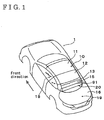
- Fig. 1 is a perspective view illustrating a vehicle including a roof opening/closing apparatus seen from an upper rear side of the vehicle, according to an embodiment
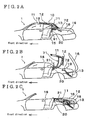
- Fig. 2A is a side view illustrating the vehicle including the roof opening/closing apparatus when a roof is in an extended position;
- Fig. 2B is a side view illustrating the vehicle including the roof opening/closing apparatus when a roof is located between the extended position and an accommodated position;
- Fig. 2C is a side view illustrating the vehicle including the roof opening/closing apparatus when a roof is in the accommodated position;
- Fig. 3 is a perspective view illustrating the roof opening/closing apparatus, according to the embodiment.
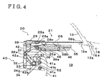
- Fig. 4 is a side view illustrating a panel moving mechanism and a panel member of the roof opening/closing apparatus when the roof is in the extended position, according to the embodiment;
- Fig. 5 is a side view illustrating the panel moving mechanism and the panel member of the roof opening/closing apparatus when the roof is moved towards the accommodated position, according to the embodiment;
- Fig. 6 is a cross sectional view, illustrating the panel moving mechanism and the panel member of the roof opening/closing apparatus when the roof is in the accommodated position, taken along line VI-VI in Fig. 3 ;
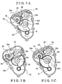
- Fig. 7A is a schematic view illustrating a driving force transmitting mechanism of the roof opening/closing apparatus when the roof is in the extended position
- Fig. 7B is a schematic view illustrating the driving force transmitting mechanism of the roof opening/closing apparatus when the panel is in an upright state while the roof is moved towards the accommodated position;
- Fig. 7C is a schematic view illustrating the driving force transmitting mechanism of the roof opening/closing apparatus when the roof is in the accommodated position.
- a vehicle 1 is a so-called convertible automobile. As illustrated in Fig. 1 , when a roof 10 is located in an extended position (serving as a first position) at which the roof 10 is extended to cover a vehicle compartment 18, the vehicle 1 is used in an enclosed mode.
- the roof 10 of the vehicle 1 is structured with a front roof 11, an intermediate roof 12 and a rear roof 13, which are longitudinally arranged from a front side to a rear side of the vehicle 1 in series when the roof 10 is located at the extended position.
- a space provided at a rear portion of the vehicle 1 is employed as an accommodating space 19, which is normally used as a trunk.
- a roof opening/closing apparatus 20 is assembled at the vehicle 1 at a position between a vehicle body portion 91 and the rear roof 13.
- the vehicle body portion 91 supports a seatback portion 15 of a seat (back seat) of the vehicle 1.
- the roof opening/closing apparatus 20 is employed for operating the roof 10 to move between the extended position and the accommodated position.
- the roof opening/closing apparatus 20 includes a plane panel member 21, which is substantially horizontally arranged when the roof 10 is located in the extended position.
- FIG. 2A, 2B and 2C A process of retracting the roof 10 from the extended position to the accommodated position is illustrated in Figs. 2A, 2B and 2C in sequential order.
- the front roof 11 and the intermediate roof 12 are supported by a first supporting mechanism 71.
- the rear roof 13 of the roof 10 is supported by a second supporting mechanism 72.
- a cover 16 of the accommodating space 19 is opened by an operation of a trunk opening/closing apparatus, and the rear roof 13 is retracted in the accommodating space 19 by an operation of the second supporting mechanism 72.
- the front roof 11 and the intermediate roof 12 are folded by the first supporting mechanism 71 and retracted to be accommodated in the accommodating space 19.
- the panel member 21 being in a horizontal position when the roof 10 is located in the extended position is moved to an upright position, at which the panel member 21 is substantially vertically arranged, by an operation of the roof opening/closing apparatus 20 so as not to interfere with extending and retracting movements of the roof 10.
- the panel member 21 is returned to the horizontal position.
- the rear roof 13 which is located between a front end of the cover 16 and the rear end of the panel member 21, is moved. Therefore, a space is generated at an upper portion of the accommodating space 19.
- the panel member 21 is extended in the longitudinal direction of the vehicle 1 by an operation of the roof opening/closing apparatus 20, thereby covering the space generated at the upper portion of the accommodating space 19 with the panel member 21 to close the accommodating space 19.
- the roof opening/closing apparatus 20 is provided inside the accommodating space 19 and divides the vehicle compartment 18 and the accommodating space 19. Further, the roof opening/closing apparatus 20 includes a panel moving mechanism 40. According to the embodiment, the roof opening/closing apparatus 20 includes right and left panel moving mechanisms 40 (serving as first and second panel moving mechanisms), which are assembled at the vehicle body portion 91 supporting the seatback portion 15 of the back seat. In Fig. 3 , a right side portion of the vehicle 1 (including the right panel moving mechanism 40) is illustrated as an example, however, the left panel moving mechanism 40 is also provided at the left side of the vehicle 1. Thus, the right and left panel moving mechanisms 40 support the panel member 21 from a lower side of the panel member 21.
- a structure of the right panel moving mechanism 40 will be described as an example of the right and left panel moving mechanisms 40
- the panel member 21 is in the horizontal position when the roof 10 is located in the accommodated position.
- the panel member 21 is structured with a front panel (serving as a first panel) and a rear panel (serving as a second panel), which are aligned in the longitudinal direction of the vehicle when the roof 10.
- the panel moving mechanism 40 includes a driving apparatus 44 serving as a driving source for moving the panel member 21 and adjusting a position thereof.
- the right and left panel moving mechanisms 40 are connected by connecting members 47a and 47b (each serving as a connecting member). Therefore, the driving apparatus 44 may be provided at one of or both of the right and left driving apparatus 44 on the basis of a size and weight of the panel member 21, which may be changed in accordance with a vehicle.
- the right and left panel moving mechanisms 40 are synchronously operated in cooperation with each other by the connecting members 47a and 47b when moving the panel member 21. Thus, torsion is prevented from being generated at the panel member 21 and also, an excessive load is prevented from being applied to the panel member 21 which extends in the width direction of the vehicle 1.
- a mechanism of the panel moving mechanism 40 and the panel member 21, when the roof 10 is located in the accommodated position is illustrated.
- Fig. 5 the mechanism of the panel moving mechanism 40 and the panel member 21, when the roof 10 is moved towards the accommodated position, is illustrated.
- the panel moving mechanism 40 includes a base bracket 41, which is fixed at the vehicle body portion 91 (see Fig. 3 ).
- the base bracket 41 supports pivot shafts 41a, 41b and 41c, each of which extends in the width direction of the vehicle 1.
- the pivot shaft 41 a is located at the uppermost position, and the pivot shaft 41c is located at the lowermost position of the three pivot shafts 41a, 41b and 41c.
- the pivot shaft 41b is positioned between the pivot shafts 41a and 41c.
- the panel moving mechanism 40 further includes a supporting bracket 42.
- the supporting bracket 42 extends horizontally in the width direction of the vehicle and includes pivot shafts 42a and 42b.
- the pivot shafts 42a and 42b are provided at the supporting bracket 42 with a predetermined distance therebetween.
- the pivot shaft 41a of the base bracket 41 and the pivot shaft 42a of the supporting bracket 31 are connected by a first link 51.
- the pivot shaft 41b of the base bracket 41 and the pivot shaft 42b of the supporting bracket 42 are connected by a second link 52.
- the base bracket 41, the supporting bracket 42, the first link 51 and the second link 52, each of which includes different length from one another, structure a four-link mechanism. More specifically, the base bracket 41, the supporting bracket 42 and the first and second links 51, 52 structure a pivotal moving mechanism 50 (see Fig. 5 ).
- the pivotal moving mechanism 50 establishes a predetermined attitude of the supporting bracket 42, in which the supporting bracket 42 is rotated relative to the base bracket 41 in accordance with a rotational angle of the first and second links 51 and 52.
- a first elongated groove hole 45 and a second elongated groove hole 46 are formed at the supporting bracket 42 with a predetermined distance from each other.
- the first and second elongated groove holes 45 and 46 extend in the longitudinal direction of the vehicle.
- a sliding bracket 35 is supported by the supporting bracket 42.
- the sliding bracket 35 includes a first pin 35a, which is inserted into the first elongated groove hole 45 and guided thereby, and a second pin 35b, which is inserted into the second elongated groove hole 46 and guided thereby.
- a cam member 36 including a cam hole 36a is fixedly attached to the sliding bracket 35.
- a pin 31a is inserted into the cam hole 36a so as to be guided thereby. Further, the pin 31 a is connected to an upper end portion of a third link 31.
- An upper end portion of a fourth link 32 and an upper end portion of a fifth link 33 are rotatably connected to a lower end portion of the third link 31 by means of a common pivot shaft 32a.
- a lower end portion of the fifth link 33 is rotatably connected to the supporting bracket 42 by means of the pivot shaft 42b, which is commonly used for the second link 52. Further, a lower end portion of the fourth link 32 is rotatably connected with one end of a sixth link 34 by means of a pivot shaft 34a. Further, another end portion of the sixth link 34 is rotatably supported by the base bracket 41 by means of a pivot shaft 41c.
- the sliding bracket 35 is operatively connected to the sixth link 34 and guided thereby via the third to fifth links 31, 32 and 33, and the sliding bracket 35 is moved in the longitudinal direction of the vehicle 1 relative to the supporting bracket 42 by a rotation of the sixth link 34.
- the sliding bracket 35 structure a sliding mechanism 30 for slidably moving the second panel 26 relative to the first panel 25.
- An assembling bracket 28 is fixedly assembled at a front upper portion of the supporting bracket 42.
- the front panel 25 is fixedly assembled to (locked to) the assembling bracket 28 by means of a locking portion 25a.
- the locking portion 25a protrudes from the front panel 25 so as to be inserted into a hole defined at the assembling bracket 28.
- the front panel 25 is structured to be easily detached from the assembling bracket 28 of the supporting bracket 42 by means of the locking portion 25a.
- the rear panel 26 is fixedly assembled to (locked to) an upper portion of the sliding bracket 35 by means of a locking portion 26c.
- the rear panel 26 is structured to be easily detached from the sliding bracket 35 by means of the locking portion 26c.
- a rear end portion 26b of the rear panel 26 is in contact with a supporting portion 13a which is formed at a lower end portion of the rear roof 13.
- a front end portion 26a of the rear panel 26 is positioned beneath the front panel 25, so that the front panel 25 and the rear panel 26 are overlapped by a predetermined range.
- a front end portion 16a of the cover 16 is in contact with a sealing member 13b assembled at the supporting position 13a of the rear roof 13, so that a space between the cover 16 and the rear roof 13 is closed. Accordingly, the accommodating space 19 is covered with the first panel 25, the rear panel 25, the supporting position 13a and the cover 16, thereby being tightly closed.
- a rear end of the panel member 21 is upwardly pivotally moved in association with the supporting bracket 42 by the operation of the pivotal moving mechanism 50, thereby opening the accommodating space 19. More specifically, the pivot shaft 41b of the link 52 rotates in the counterclockwise direction in Fig. 5 by a driving force of the driving apparatus 44, which is transmitted via the driving force transmitting mechanism 60 (described below in detail), thereby moving the panel member 21 to be in the upright position.
- the panel member 21 is moved to the upright position so as to be away from the locus A of the front roof 11.
- the panel member 21 is structured so as not to interfere with the movement of the roof 10 moved between the accommodated position and the extended position.
- the pivot shaft 41 connected to the sixth link 34 rotates in the clockwise direction by the driving force of the driving apparatus 44, which is transmitted via the driving force transmitting mechanism 60.
- the sliding mechanism 30 is operated, so that the sliding bracket 35 is moved further backwardly than a position indicated in Fig. 4 by being guided by the first and second elongated groove holes 45, 46 of the supporting bracket 42.
- the rear end portion 26a of the rear panel 26 is moved in association with the sliding bracket 35 to a position at which the rear end portion 26a directly makes contact with the front end portion 16a of the cover 16 so as to close the space generated between the cover 16 and the supporting position 13a of the rear roof 13 when the rear roof 13 is retracted.
- the accommodating space 19 is closed even when the roof 10 is moved to the accommodated position.
- the first elongated groove hole 45 includes a bent groove portion 45a, which is formed at a rear end portion of the first elongated groove hole 45 by upwardly bending the same.
- the pin 31 a is operated to upwardly move the cam member 36
- the pin 35a is fitted into the vent groove portion 45a of the first elongated groove hole 45.
- the front end portion 26a of the rear panel 26 is upwardly moved.
- the rear end portion 26a of the rear panel 26 is in contact with a lower surface of the front panel 25, and upper surfaces of the rear panel 26 and the front panel 25 structure a successive plane surface. Therefore, an excellent appearance of the convertible automobile is established.
- the driving force transmitting mechanism 60 includes a driving gear 61, a gear 62 for the sliding mechanism 30 and a gear 63 for the pivotal moving mechanism 50.
- the diving gear 61 rotates by a driving force of an electric motor incorporated in a driving apparatus 44.
- a shaft 62c of the gear 62 for the sliding mechanism 30 is connected with the pivot shaft 41 c to rotate the sixth link 34 (see Fig. 4 ).
- a shaft 63c of the gear 63 for the pivotal moving mechanism 50 is connected with the pivot shaft 41b to rotate the second link 52 (see Fig. 4 ).
- the gears 62 and 63 are intermittent gears, which respectively include teeth portions at a predetermined angular range and which do not rotate by 360-degrees, and are employed for pivotally moving (rotating) the sixth link 34 and the second link 52, respectively.
- the driving gear 61 is engaged with the gear 62.
- An arc shaped driven gear 62d is integrally provided at the gear 62 so as to rotate therewith.
- An intermediate gear 64 is engaged with the driven gear 62d of the gear 62.
- the intermediate gear 64 also includes a teeth portion at a predetermined angular range and does not rotate by 360-degrees.
- An arc-shaped driven gear 64a is integrally provided at the intermediate gear 64 so as to rotate therewith.
- the gear 63 is engaged with the driven gear 64a of the intermediate gear 64.
- the driving gear 61 rotates in the clockwise direction as illustrated in Fig. 7A so as to move the panel member 21 to the upright position.
- the gear 62 engaged with the driving gear 61 and the driven gear 62d of the gear 62 rotates in the counterclockwise direction.
- the intermediate gear 64 and the driven gear 64a thereof, which are engaged with the driven gear 62d of the gear 62 rotate in the clockwise direction.
- the gear 63 for the pivotal moving mechanism 50 is rotated by being engaged with the driven gear 64a of the intermediate gear 64.
- the transmitting mechanism 60 is in a state as illustrated in Fig. 7B . Consequently, the second link 52 (see Fig. 5 ) rotates in the counterclockwise direction, and the panel member 21 is moved to the upright position by the operation of the pivotal moving mechanism 50.
- the driving gear 61 rotates in the counterclockwise direction so as to backwardly pivotally (rotationally) move the rear panel 26.
- the gear 62 engaged with the driving gear 61 and the driven gear 62d rotate in the clockwise direction.
- the intermediate gear 64 and the driven gear 64a thereof, which are engaged with the driven gear 62d rotate in the counterclockwise direction, so that the gear 63 engaged with the driven gear 64a rotates in the clockwise direction.
- the panel member 21 is tilted towards the horizontal position.
- the driving force transmitting mechanism 60 is in the state as illustrated in Fig. 7A .
- an engagement member 65 and an engagement member 66 are engaged with each other.
- the engagement member 65 includes an arc-shaped protruding surface (convex surface) and is integrally provided at the intermediate gear 64 so as to rotate therewith.
- the engagement member 66 includes an arc-shaped recessed surface (concave surface) and is integrally provided at the gear 63 so as to rotate therewith.
- the roof opening/closing apparatus 20 and the retracting and extending operations of the roof 10 which are performed by the first and second supporting mechanisms 71 and 72 are controlled on the basis of a controlling program stored in a roof controlling apparatus included in the vehicle 1.
- the panel member 21 is easily detachable from the panel moving mechanism 40. Further, a moving range of the front panel 25 and the rear panel 26 is changed by a controlling program stored in a controlling apparatus of the panel moving mechanism 40 and is converted to a movement of the panel member 21. So configured, even when the panel member 21 is changed to another panel member of which shape is different from the panel member 21, a structure of the panel member is rarely changed. Accordingly, the structure of the panel member 21 is applied to various types of vehicles at a lower cost.
- the panel member 21 is structured with the front panel 25 (serving as the first panel) and the rear panel 26 (serving as the second panel), which are longitudinally aligned.
- another panel serving as a third panel
- the panel member 21 may be structured with plural panels.
- the sliding mechanism 30 slidably moves the rear panel 26 relative to the front panel 25 for adjusting a length of the panel member 21 in the longitudinal direction of the vehicle 1. More specifically, by the operation of the sliding mechanism 30, the front and rear panels 25, 26 are overlapped when the roof 10 is located in the extended position, thereby reducing the length of the panel member 21 in the longitudinal direction of the vehicle to be smaller than the length of the panel member 21 when the roof is located in the accommodated position.
- the panel moving mechanism 40 is provided under the panel member 21 to support the panel member 21 from the lower side thereof. Accordingly, even though the weight of the panel member is reduced, the strength and rigidity of the panel member 21 is ensured.
- the sliding mechanism 30 and the pivotal moving mechanism 50 are included in the unit of the panel moving mechanism 40. Therefore, the roof opening/closing apparatus 20 is downsized.
- the force transmitting mechanism 60 including the intermittent motion gear mechanism the sliding mechanism 30 and the pivotal moving mechanism 50 are actuated with the same (common) driving apparatus 40. Therefore, the number of components is reduced, so that the roof opening/closing apparatus 20 is produced at low cost.
- the panel member 21 is supported by the right and left panel moving mechanisms 40.
- the strength of the panel member 21 is enhanced.
- the excessive load is prevented from being applied to the panel member 21.
- the panel member 21 is surely moved to a predetermined position.
- the panel member 21 is detachable to the panel moving mechanism 40, the moving range between the front panel 25 and the rear panel 26 is changed by the change of the controlling program of the controlling apparatus of the panel moving mechanism 40. So configured, even when the panel member 21 is changed to another panel member of which shape is different from the panel member 21, the structure of the panel member 21 is applied to various types of vehicles at the lower cost without changing the expensive panel moving mechanism 40.
Landscapes
- Engineering & Computer Science (AREA)
- Mechanical Engineering (AREA)
- Body Structure For Vehicles (AREA)
- Lock And Its Accessories (AREA)
Claims (4)
- Dachöffnungs- und -schließvorrichtung (20) zum Bewegen eines Dachs (10) eines Fahrzeugs (1) zwischen einer ersten Position, an der das Dach (10) ausgefahren ist, um einen Innenraum (18) des Fahrzeugs (1) zu bedecken, und einer zweiten Position, an der das Dach (10) in einem Aufnahmeraum (19) des Fahrzeugs (1) aufgenommen ist, wobei die Dachöffnungs- und -schließvorrichtung (20) aufweist:ein Paneelelement (21) zur Bedeckung eines oberen Abschnitts des Aufnahmeraums (19), wobei das Paneelelement (21) ein erstes Paneel (25) und ein zweites Paneel (26) aufweist, die in Längsrichtung des Fahrzeugs (1) ausgerichtet sind, wobei das zweite Paneel (26) an einer Rückseite des ersten Paneels (25) angeordnet ist; undeinen Paneel-Bewegungsmechanismus (40), der innerhalb des Aufnahmeraums (19) und unter dem Paneelelement (21) vorgesehen ist und das erste Paneel (25) und das zweite Paneel (26) beweglich stützt,wobei der Paneel-Bewegungsmechanismus (40) aufweist:einen Schiebemechanismus (30), der das zweite Paneel (26) relativ zu dem ersten Paneel (25) so verschiebt, dass sich das erste Paneel (25) und das zweite Paneel (26) überlappen, wenn sich das Dach (10) in der ersten Position befindet, und eine Länge des Paneelelements (21) in Längsrichtung des Fahrzeugs (1) so verringert wird, dass sie kleiner ist als die Länge des Paneelelements (21), wenn sich das Dach (10) in der zweiten Position befindet, undeinen Drehbewegungsmechanismus (50) zur drehenden Bewegung des Paneelelements (21), wenn das Dach (10) zwischen der ersten Position und der zweiten Position bewegt wird, dadurch gekennzeichnet, dassder Paneel-Bewegungsmechanismus (40) einen Antriebskraft-Übertragungsabschnitt (60) mit einem Getriebemechanismus für intermittierende Bewegungen aufweist, durch den der Schiebemechanismus (30) und der Drehbewegungsmechanismus (50) durch eine gebräuchliche Antriebsvorrichtung (44) intermittierend angetrieben werden.
- Dachöffnungs- und -schließvorrichtung (20) nach Anspruch 1, wobei
der Paneel-Bewegungsmechanismus (40) einen ersten Paneel-Bewegungsmechanismus (40) und einen zweiten Paneel-Bewegungsmechanismus (40) aufweist, die in einem vorgegebenen Abstand voneinander unter dem Paneelelement (21) vorgesehen sind, und
ein Verbindungselement (47a, 47b) den ersten und den zweiten Paneel-Bewegungsmechanismus (40) miteinander verbindet, um den ersten und den zweiten Paneel-Bewegungsmechanismus (40) so anzutreiben, dass diese sich miteinander bewegen. - Dachöffnungs- und -schließvorrichtung (20) nach Anspruch 1 oder 2, die weiterhin aufweist:einen Verriegelungsabschnitt (26c), der das Paneelelement (21) lösbar mit dem Paneel-Bewegungsmechanismus (40) verriegelt.
- Dachöffnungs- und -schließvorrichtung (20) nach einem der Ansprüche 1 bis 3, wobei die Drehbewegung des Paneelelements (21) nach oben gerichtet endet.
Applications Claiming Priority (1)
| Application Number | Priority Date | Filing Date | Title |
|---|---|---|---|
| JP2007310260A JP5157396B2 (ja) | 2007-11-30 | 2007-11-30 | ルーフ収納装置 |
Publications (3)
| Publication Number | Publication Date |
|---|---|
| EP2065240A2 EP2065240A2 (de) | 2009-06-03 |
| EP2065240A3 EP2065240A3 (de) | 2009-12-09 |
| EP2065240B1 true EP2065240B1 (de) | 2011-03-30 |
Family
ID=40215839
Family Applications (1)
| Application Number | Title | Priority Date | Filing Date |
|---|---|---|---|
| EP08169988A Not-in-force EP2065240B1 (de) | 2007-11-30 | 2008-11-26 | Vorrichtung zum Öffnen/Schließen eines Fahrzeugdachs |
Country Status (4)
| Country | Link |
|---|---|
| US (1) | US7862099B2 (de) |
| EP (1) | EP2065240B1 (de) |
| JP (1) | JP5157396B2 (de) |
| DE (1) | DE602008005824D1 (de) |
Cited By (1)
| Publication number | Priority date | Publication date | Assignee | Title |
|---|---|---|---|---|
| DE102014116211B3 (de) * | 2014-11-06 | 2016-04-28 | Webasto-Edscha Cabrio GmbH | Verdeck eines Cabriolet-Fahrzeugs mit einer Hutablage |
Families Citing this family (4)
| Publication number | Priority date | Publication date | Assignee | Title |
|---|---|---|---|---|
| JP5245610B2 (ja) * | 2008-07-28 | 2013-07-24 | アイシン精機株式会社 | パネル移動装置 |
| DE102008053218A1 (de) * | 2008-10-25 | 2010-05-20 | Audi Ag | Vorrichtung zur Festlegung der Lage einer Klappe |
| EP2196343A1 (de) * | 2008-12-12 | 2010-06-16 | Mazda Motor Corporation | Dachöffnungsstruktur für ein Fahrzeug |
| US10362738B2 (en) * | 2015-09-10 | 2019-07-30 | Komatsu Ltd. | Work vehicle |
Family Cites Families (28)
| Publication number | Priority date | Publication date | Assignee | Title |
|---|---|---|---|---|
| US4687247A (en) * | 1985-05-13 | 1987-08-18 | Muscat Peter P | Powered tonneau cover for convertible automobiles |
| JPH0242485Y2 (de) * | 1986-07-16 | 1990-11-13 | ||
| JPS62295900A (ja) | 1987-05-15 | 1987-12-23 | 株式会社豊田自動織機製作所 | フォークリフト用コンテナスプレッダ |
| DE4446483C2 (de) | 1994-12-23 | 1998-02-26 | Daimler Benz Ag | Hardtop-Fahrzeug |
| DE19538738C1 (de) * | 1995-10-18 | 1997-01-23 | Porsche Ag | Abdeckklappe für eine oberhalb eines Verdecklagers befindliche Durchlaßöffnung in einer Bordwand eines Fahrzeuges |
| DE19613917C2 (de) * | 1996-04-06 | 1998-01-15 | Daimler Benz Ag | Abdeckanordnung für einen im Heckbereich eines Fahrzeugs angeordneten Verdeckkasten |
| US6217104B1 (en) * | 1999-06-16 | 2001-04-17 | Cts Fahrzeug Dachsysteme Gmbh | Retractable hard top module |
| JP4292354B2 (ja) * | 1999-10-19 | 2009-07-08 | アイシン精機株式会社 | 車両用パッケージトレイ |
| DE10036223B4 (de) * | 2000-07-26 | 2004-07-29 | Cts Fahrzeug-Dachsysteme Gmbh | Mehrteilige Abdeckung für den Aufnahmeraum eines Verdeckes |
| US6254165B1 (en) * | 2000-08-16 | 2001-07-03 | Cts Fahrzeug Dachsysteme Gmbh | Tonneau cover and decklid linkage and drive system |
| DE10050286B4 (de) * | 2000-10-10 | 2004-08-05 | Cts Fahrzeug-Dachsysteme Gmbh | Mehrteilige Abdeckung für Fahrzeuge |
| DE10134370B4 (de) * | 2001-07-14 | 2006-01-05 | Daimlerchrysler Ag | Abdeckvorrichtung für einen Verdeckkasten |
| DE10134373B4 (de) * | 2001-07-14 | 2006-01-05 | Daimlerchrysler Ag | Abdeckvorrichtung für einen Verdeckkasten |
| DE10134369C2 (de) * | 2001-07-14 | 2003-05-15 | Daimler Chrysler Ag | Abdeckvorrichtung für einen Verdeckkasten |
| JP4004261B2 (ja) * | 2001-09-28 | 2007-11-07 | ダイハツ工業株式会社 | 車両のルーフ格納構造 |
| FR2834953B1 (fr) * | 2002-01-21 | 2004-06-04 | France Design | Dispositif de commande d'une tablette arriere de vehicule automobile |
| FR2834951B1 (fr) * | 2002-01-21 | 2004-06-04 | France Design | Tablette arriere pour vehicule automobile dote d'un toit repliable |
| FR2839474B1 (fr) * | 2002-05-13 | 2005-01-14 | France Design | Plage arriere de vehicule |
| DE10222189B4 (de) * | 2002-05-18 | 2008-09-04 | Daimler Ag | Abdeckvorrichtung für einen Verdeckkasten eines Cabriolet-Fahrzeugs |
| DE10247725B4 (de) * | 2002-10-12 | 2006-08-24 | Wilhelm Karmann Gmbh | Cabriolet-Fahrzeug mit versenkbarem Verdeck |
| FR2851510A1 (fr) * | 2003-02-21 | 2004-08-27 | Renault Sa | Dispositif de toit escamotable et vehicule equipe d'un tel dispositif |
| FR2851509A1 (fr) * | 2003-02-21 | 2004-08-27 | Renault Sa | Dispositif de toit escamotable et vehicule equipe d'un tel dispositif |
| FR2853868B1 (fr) * | 2003-04-15 | 2005-06-24 | France Design | Systeme de plage arriere escamotable pour vehicule decouvrable a toit repliable |
| DE10357097A1 (de) * | 2003-12-06 | 2005-06-30 | Wilhelm Karmann Gmbh | Bewegliche Ablagefläche und Vorrichtung zum Halten einer solchen Ablagefläche sowie Fahrzeug mit einer solchen Ablagefläche und/oder einer solchen Halterung |
| JP2005231460A (ja) * | 2004-02-18 | 2005-09-02 | Toyo Seat Co Ltd | コンバーチブルトップ車のトノカバー構造 |
| DE102004048405B4 (de) * | 2004-10-01 | 2006-06-01 | Cts Fahrzeug-Dachsysteme Gmbh | Kinematik zum Verstellen einer Seitenklappe einer Abdeckanordnung für Fahrzeuge mit öffnungsfähigem Fahrzeugdach |
| DE102005047297B3 (de) | 2005-09-30 | 2007-02-22 | Ise Industries Gmbh | Antriebsvorrichtung für einen Verdeckkastendeckel eines Kraftfahrzeugs |
| DE102005057651B4 (de) * | 2005-12-01 | 2008-02-14 | Magna Car Top Systems Gmbh | Fahrzeug mit Abdeckanordnung |
-
2007
- 2007-11-30 JP JP2007310260A patent/JP5157396B2/ja not_active Expired - Fee Related
-
2008
- 2008-11-25 US US12/292,746 patent/US7862099B2/en not_active Expired - Fee Related
- 2008-11-26 EP EP08169988A patent/EP2065240B1/de not_active Not-in-force
- 2008-11-26 DE DE602008005824T patent/DE602008005824D1/de active Active
Cited By (1)
| Publication number | Priority date | Publication date | Assignee | Title |
|---|---|---|---|---|
| DE102014116211B3 (de) * | 2014-11-06 | 2016-04-28 | Webasto-Edscha Cabrio GmbH | Verdeck eines Cabriolet-Fahrzeugs mit einer Hutablage |
Also Published As
| Publication number | Publication date |
|---|---|
| DE602008005824D1 (de) | 2011-05-12 |
| EP2065240A3 (de) | 2009-12-09 |
| JP2009132284A (ja) | 2009-06-18 |
| US20090140540A1 (en) | 2009-06-04 |
| EP2065240A2 (de) | 2009-06-03 |
| US7862099B2 (en) | 2011-01-04 |
| JP5157396B2 (ja) | 2013-03-06 |
Similar Documents
| Publication | Publication Date | Title |
|---|---|---|
| JP3771877B2 (ja) | ルーフ機構格納部のカバー装置 | |
| EP1842710B1 (de) | Einziehbares Dach und Fahrzeug damit | |
| EP2006139B1 (de) | Versenkbares dach und fahrzeug damit | |
| EP2065240B1 (de) | Vorrichtung zum Öffnen/Schließen eines Fahrzeugdachs | |
| JPS63173722A (ja) | 車両のオ−プンル−フ構造 | |
| EP2149467B1 (de) | Dachöffnungs- und -schließvorrichtung für ein Fahrzeug | |
| EP1334856A2 (de) | Vorrichtung zur Öffnung einer Flügeltür eines Kraftfahrzeugs | |
| US7963584B2 (en) | Retractable roof and vehicle including the same | |
| JP3640841B2 (ja) | サンルーフ装置 | |
| JP4958479B2 (ja) | リトラクタブルルーフ、及びそれを備えた車両 | |
| CN107199858B (zh) | 汽车的顶棚构造 | |
| JP5778924B2 (ja) | 車両用リアゲートの開閉装置 | |
| JP6764907B2 (ja) | 自動車のルーフ構造 | |
| JP2006347397A (ja) | 格納式ハードパネルルーフの開閉装置 | |
| JPH0628974B2 (ja) | 自動車のオ−プンル−フ操作装置 | |
| JP2012086612A (ja) | 車両の可動ルーフ構造 | |
| JP5582869B2 (ja) | コンソールボックス | |
| JP2005053390A (ja) | 自動車のルーフ構造 | |
| JP2005219570A (ja) | ニーボルスタ構造 | |
| JP2009241747A (ja) | 自動車のシート格納構造 | |
| JP2007290415A (ja) | 車両用シート装置 | |
| JP2005053379A (ja) | 自動車のルーフ構造 | |
| JPH1086718A (ja) | シートバック用リクライニング機構のレリーズ構造 | |
| JP2007297007A (ja) | 自動車のルーフ格納機構 | |
| JP2005053391A (ja) | 自動車のルーフ収納構造 |
Legal Events
| Date | Code | Title | Description |
|---|---|---|---|
| PUAI | Public reference made under article 153(3) epc to a published international application that has entered the european phase |
Free format text: ORIGINAL CODE: 0009012 |
|
| AK | Designated contracting states |
Kind code of ref document: A2 Designated state(s): AT BE BG CH CY CZ DE DK EE ES FI FR GB GR HR HU IE IS IT LI LT LU LV MC MT NL NO PL PT RO SE SI SK TR |
|
| AX | Request for extension of the european patent |
Extension state: AL BA MK RS |
|
| PUAL | Search report despatched |
Free format text: ORIGINAL CODE: 0009013 |
|
| AK | Designated contracting states |
Kind code of ref document: A3 Designated state(s): AT BE BG CH CY CZ DE DK EE ES FI FR GB GR HR HU IE IS IT LI LT LU LV MC MT NL NO PL PT RO SE SI SK TR |
|
| AX | Request for extension of the european patent |
Extension state: AL BA MK RS |
|
| 17P | Request for examination filed |
Effective date: 20091204 |
|
| AKX | Designation fees paid |
Designated state(s): DE FR |
|
| GRAP | Despatch of communication of intention to grant a patent |
Free format text: ORIGINAL CODE: EPIDOSNIGR1 |
|
| RIN1 | Information on inventor provided before grant (corrected) |
Inventor name: FUKADA, RYUTAAISIN ENGINEERING CO., LTD. Inventor name: INOUE, KASTURAAISIN ENGINEERING CO., LTD. Inventor name: HAYASHI, KENICHIROAISIN SEIKI KABUSHIKI KAISHA |
|
| GRAS | Grant fee paid |
Free format text: ORIGINAL CODE: EPIDOSNIGR3 |
|
| GRAA | (expected) grant |
Free format text: ORIGINAL CODE: 0009210 |
|
| RTI1 | Title (correction) |
Free format text: VEHICLE ROOF OPENING/CLOSING APPARATUS |
|
| AK | Designated contracting states |
Kind code of ref document: B1 Designated state(s): DE FR |
|
| REF | Corresponds to: |
Ref document number: 602008005824 Country of ref document: DE Date of ref document: 20110512 Kind code of ref document: P |
|
| REG | Reference to a national code |
Ref country code: DE Ref legal event code: R096 Ref document number: 602008005824 Country of ref document: DE Effective date: 20110512 |
|
| PLBE | No opposition filed within time limit |
Free format text: ORIGINAL CODE: 0009261 |
|
| STAA | Information on the status of an ep patent application or granted ep patent |
Free format text: STATUS: NO OPPOSITION FILED WITHIN TIME LIMIT |
|
| 26N | No opposition filed |
Effective date: 20120102 |
|
| REG | Reference to a national code |
Ref country code: DE Ref legal event code: R097 Ref document number: 602008005824 Country of ref document: DE Effective date: 20120102 |
|
| REG | Reference to a national code |
Ref country code: FR Ref legal event code: PLFP Year of fee payment: 8 |
|
| REG | Reference to a national code |
Ref country code: FR Ref legal event code: PLFP Year of fee payment: 9 |
|
| REG | Reference to a national code |
Ref country code: FR Ref legal event code: PLFP Year of fee payment: 10 |
|
| REG | Reference to a national code |
Ref country code: FR Ref legal event code: PLFP Year of fee payment: 11 |
|
| PGFP | Annual fee paid to national office [announced via postgrant information from national office to epo] |
Ref country code: DE Payment date: 20191112 Year of fee payment: 12 |
|
| PGFP | Annual fee paid to national office [announced via postgrant information from national office to epo] |
Ref country code: FR Payment date: 20191014 Year of fee payment: 12 |
|
| REG | Reference to a national code |
Ref country code: DE Ref legal event code: R119 Ref document number: 602008005824 Country of ref document: DE |
|
| PG25 | Lapsed in a contracting state [announced via postgrant information from national office to epo] |
Ref country code: FR Free format text: LAPSE BECAUSE OF NON-PAYMENT OF DUE FEES Effective date: 20201130 |
|
| PG25 | Lapsed in a contracting state [announced via postgrant information from national office to epo] |
Ref country code: DE Free format text: LAPSE BECAUSE OF NON-PAYMENT OF DUE FEES Effective date: 20210601 |