EP2056528A1 - Appareil de communication sans fil, système lan sans fil, procédé de détection d'interférence, et procédé d'évitement d'interférence - Google Patents
Appareil de communication sans fil, système lan sans fil, procédé de détection d'interférence, et procédé d'évitement d'interférence Download PDFInfo
- Publication number
- EP2056528A1 EP2056528A1 EP07706998A EP07706998A EP2056528A1 EP 2056528 A1 EP2056528 A1 EP 2056528A1 EP 07706998 A EP07706998 A EP 07706998A EP 07706998 A EP07706998 A EP 07706998A EP 2056528 A1 EP2056528 A1 EP 2056528A1
- Authority
- EP
- European Patent Office
- Prior art keywords
- interference
- error
- packet
- wireless communication
- transmission
- Prior art date
- Legal status (The legal status is an assumption and is not a legal conclusion. Google has not performed a legal analysis and makes no representation as to the accuracy of the status listed.)
- Withdrawn
Links
Images


Classifications
-
- H—ELECTRICITY
- H04—ELECTRIC COMMUNICATION TECHNIQUE
- H04L—TRANSMISSION OF DIGITAL INFORMATION, e.g. TELEGRAPHIC COMMUNICATION
- H04L1/00—Arrangements for detecting or preventing errors in the information received
- H04L1/12—Arrangements for detecting or preventing errors in the information received by using return channel
- H04L1/16—Arrangements for detecting or preventing errors in the information received by using return channel in which the return channel carries supervisory signals, e.g. repetition request signals
- H04L1/18—Automatic repetition systems, e.g. Van Duuren systems
- H04L1/1867—Arrangements specially adapted for the transmitter end
-
- H—ELECTRICITY
- H04—ELECTRIC COMMUNICATION TECHNIQUE
- H04B—TRANSMISSION
- H04B17/00—Monitoring; Testing
- H04B17/30—Monitoring; Testing of propagation channels
- H04B17/309—Measuring or estimating channel quality parameters
- H04B17/345—Interference values
-
- H—ELECTRICITY
- H04—ELECTRIC COMMUNICATION TECHNIQUE
- H04L—TRANSMISSION OF DIGITAL INFORMATION, e.g. TELEGRAPHIC COMMUNICATION
- H04L1/00—Arrangements for detecting or preventing errors in the information received
- H04L1/0001—Systems modifying transmission characteristics according to link quality, e.g. power backoff
- H04L1/0002—Systems modifying transmission characteristics according to link quality, e.g. power backoff by adapting the transmission rate
-
- H—ELECTRICITY
- H04—ELECTRIC COMMUNICATION TECHNIQUE
- H04L—TRANSMISSION OF DIGITAL INFORMATION, e.g. TELEGRAPHIC COMMUNICATION
- H04L1/00—Arrangements for detecting or preventing errors in the information received
- H04L1/0001—Systems modifying transmission characteristics according to link quality, e.g. power backoff
- H04L1/0006—Systems modifying transmission characteristics according to link quality, e.g. power backoff by adapting the transmission format
- H04L1/0007—Systems modifying transmission characteristics according to link quality, e.g. power backoff by adapting the transmission format by modifying the frame length
-
- H—ELECTRICITY
- H04—ELECTRIC COMMUNICATION TECHNIQUE
- H04L—TRANSMISSION OF DIGITAL INFORMATION, e.g. TELEGRAPHIC COMMUNICATION
- H04L1/00—Arrangements for detecting or preventing errors in the information received
- H04L1/12—Arrangements for detecting or preventing errors in the information received by using return channel
- H04L1/16—Arrangements for detecting or preventing errors in the information received by using return channel in which the return channel carries supervisory signals, e.g. repetition request signals
- H04L1/18—Automatic repetition systems, e.g. Van Duuren systems
- H04L1/1825—Adaptation of specific ARQ protocol parameters according to transmission conditions
Definitions
- the present invention relates to a wireless communication apparatus, wireless LAN system, interference detecting method and interference avoidance method for detecting and avoiding interference where interference occurs.
- WLAN Wireless Local Area Network
- IEEE802.11 standardized by the IEEE (Institute of Electrical and Electronics Engineers). This standardized technique defines layers in an OSI model from a physical layer to a MAC (Medium Access Control) layer, which is a lower layer of a data link, is substitutable for Ethernet, which is a wired LAN channel and is furthermore based on a specification capable of providing also a roaming function, which is an additional function taking advantage of being wireless.
- MAC Medium Access Control
- WLAN Wireless Local Area Network
- Bluetooth registered trademark
- UWB Ultra Wideband
- Patent Document 1 discloses one in which a wireless communication section is provided with a 2.4 GHz band front-end circuit and a 5 GHz band front-end circuit to handle two frequency bands of 2.4 GHz band and 5 GHz band and to thereby drastically increase the number of channels simultaneously settable by a WLAN system in the same area and reduce the possibility that the communication link may be interrupted by jamming.
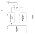
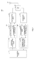
- FIG.1 shows a configuration of a wireless communication apparatus on a conventional WLAN.
- wireless communication apparatus 10 is constructed by including antenna 11, transmission/reception changeover switch (T/R SW) 12, WLAN transmitting circuit 13, WLAN receiving circuit 14 and WLAN control circuit 15.
- T/R SW transmission/reception changeover switch
- Transmission/reception changeover switch (T/R SW) 12 switches a SW at transmission timing and reception timing.
- WLAN transmitting circuit 13 transmits a signal on the WLAN.
- WLAN receiving circuit 14 receives a signal on the WLAN.
- WLAN control circuit 15 controls WLAN transmitting circuit 13 and WLAN receiving circuit 14.
- the WLAN can move each terminal that makes up the WLAN within a communicable range and has a high degree of portability, but the boundary marking the communicable range is ambiguous. Since the boundary marking the communicable range is ambiguous, when a plurality of neighboring WLANs exist, terminals may be located within a range in which communicable ranges of the plurality of WLANs overlap with each other. These terminals mutually receive their respective waves within the mutually neighboring WLANs, which may cause a problem of jamming and reduce throughput.
- Patent Document 2 discloses a technique of detecting interference based on an ID reception rate of a BSS (Basic Service Set) received from other than an AP (Access Point) with which the own station is communicating.
- the jamming detecting method described in Patent Document 2 detects whether or not interference has occurred between BSSs based on an outside BSSID reception rate calculation section that calculates a reception rate of frames including IDs of other BSSs which are different from an ID of the corresponding BSS among all received frames and the outside BSSID reception rate calculated by this outside BSSID reception rate calculation section.
- Patent Document 3 discloses a technique of identifying interference based on received power of a received signal transmitted from a wireless device other than an AP with which the own station is communicating.
- Thejammingdecision method describedin Patent Document 3 is provided with a function of deciding the degree of interference from an interference amount monitoring signal outputted from a wireless interface section, changing the operating channel and thereby deciding whether or not interference should be avoided.
- Patent Document 4 discloses a technique of avoiding, when jamming is detected, the jamming by changing a frequency channel.
- the jamming avoidance method described in Patent Document 4 measures, when selectively setting a plurality of frequency channels in a wireless network system to access a device terminal via wireless communication, radio wave levels of a plurality of frequency channels based on a signal received through a radio antenna at predetermined intervals, compares the measured radio wave levels with a predetermined threshold, decides whether or not to use each frequency channel, stores each frequency channel as statistical data of the frequency of use and changes the frequency channel based on the statistical data as required in execution of wireless communication with the above-described device terminal.
- Patent Document 5 provides, when an error occurs due to interference, reference throughput at the time of interference and controls the speed mode so as to reach the throughput to secure a certain level of throughput in order to avoid a drastic drop of throughput caused by a drop of the transmission rate to a minimum rate through fallback.
- the wireless communication apparatus detects the presence/absence of interference from an interfering device which operates in the same frequency band as the frequency band to be received by the wireless communication apparatus and operates based on a standard different from the standard used for communication of the wireless communication apparatus, the wireless communication apparatus sets a throughput that serves as a reference in changing the speed mode as an interference throughput and thereby changes the speed mode.
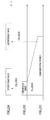
- FIGs.2A to C show a relationship between an interference wave and a communication carrier.
- interference waves occur periodically or in a burst-like manner.
- a communication carrier under jamming (see FIG.2B ) is controlled so as to drop a transmission rate through fallback in the same way as in a case where a communication error has occurred and extend the transmission distance (see FIG.2C ).
- the above-described communication carrier refers to a packet length of a frequency band in which the wireless communication apparatus performs transmission/reception here, and upon detecting an interference wave, the wireless communication apparatus performs fallback control that changes a throughput setting and drops a transmission rate.
- fallback As shown in FIG.2C , through the fallback, the packet length is increased and the communication packet extends on the time axis, and therefore the communication packet after the fallback is more likely to collide with the next interference wave. That is, fallback always causes the communication packet to be directed in a direction in which the communication packet collides with an interference wave.
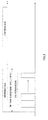
- FIG.3 shows a relationship between an interference wave and the number of packet retransmissions.
- the number of retransmissions in a time domain in which an interference wave occurs is 3 to 7 to avoid jitter in the wireless interval.
- the packet length is small, even repeating retransmission 3 to 7 times cannot exceed the time domain in which an interference wave occurs and cannot avoid interference waves. That is, since the number of retransmissions is small, the time domain free of interference waves cannot be reached.
- FIGs.4A and B show a relationship between an interference wave and the number of packet retransmissions
- FIG.4A illustrates above-described problem (1)
- FIG.4B illustrates above-described problem (2).
- a microwave When a microwave is turned on in a frequency band of a communication carrier with which a wireless communication apparatus is carrying out transmission/reception, this microwave becomes a source of interference wave and the period in which the microwave is switched on becomes an interference period.
- the microwave produces jamming over a wide range of frequency band including a 2.4 GHz frequency band used by a WLAN and causes interference in a burst-like manner when the microwave is switched on and furthermore produces interference completely asynchronously with the WLAN.
- a beacon is periodically transmitted from an access point and has a packet length of about 1 msec.
- interference occurs during transmission and even when retransmissions 1, 2, 3,... are repeated, since the predetermined number of retransmissions is a small number, retransmissions exceeding the ON interval (i.e. interference period) of the microwave do not succeed and cannot avoid interference.
- the present invention has been implemented in view of the above-described problems and it is therefore an object of the present invention to provide a wireless communication apparatus, wireless LAN system, interference detecting method and interference avoidance method for detecting whether a communication error occurs due to occurrence of interference.
- the wireless communication apparatus of the present invention adopts a configuration including: a communication status deciding section that decides a wireless communication status; a packet error detecting section that detects an error with a transmitted or received packet; and an interference error deciding section that decides, when the wireless communication status decided in the communication status deciding section shows a predetermined interference decision condition, an interference error from an interference source when an error is detected in the packet error detecting section.
- the wireless communication apparatus of the present invention is a wireless communication apparatus that performs fallback control to reduce transmission rate when a communication error occurs, and adopts a configuration including an interference avoidance control section that stops, when an interference error is detected, the fallback control, fixes the transmission rate to a certain rate and increases the number of retransmissions compared to the count for during normal communication.
- the wireless communication apparatus of the present invention is a wireless communication apparatus that performs rate control that increases a transmission rate when a communication error is corrected, and adopts a configuration including an interference avoidance control section that stops, when an interference error is detected, fallback control, fixes a transmission rate to a certain rate and increases the number of retransmissions compared to the count for during normal communication.
- the wireless LAN system of the present invention is a wireless LAN system that connects a plurality of wireless communication apparatuses via a wireless network and adopts a configuration including the above-described wireless communication apparatus.
- the interference detecting method of the present invention includes the steps of: measuring an energy detect value before packet transmission; detecting an acknowledgment error with respect to a transmitted packet; and identifying an interference error when the acknowledgment error is detected with respect to the packet transmitted under a condition that the measured energy detect value exceeds an interference deciding threshold.
- the interference detecting method of the present invention includes the steps of: measuring an energy detect value before packet transmission; detecting a transmission error that a transmitted packet cannot be retransmitted in a predetermined number of retransmissions; and identifying an interference error when the transmission error is detected from the packet transmitted under a condition that the measured energy detect value exceeds an interference deciding threshold.
- the interference detecting method of the present invention includes the steps of: measuring the noisefloor value which is the noise level of when a packet is received; detecting a reception error with the received packet including a frame check sequence error; and identifying an interference error when the reception error is detected from the packet received under a condition that the measured noisefloor value exceeds an interference deciding threshold.
- the interference detecting method of the present invention includes the steps of: measuring the noisefloor value of when a beacon is received; detecting a reception error with a received packet including a frame check sequence error; and identifying an interference error when the reception error is detected with the packet received under a condition that the measured noisefloor value exceeds an interference deciding threshold.
- the interference avoidance method of the present invention includes the steps of stopping, when an interference error is detected, fallback control to reduce transmission rate and fixing the transmission rate to a certain rate and increasing the number of retransmissions compared to the count for during normal communication.
- the present invention makes it in fact possible to detect communication errors that occur due to occurrence of interference.
- Embodiments 1 to 3 are application examples of an interference detecting circuit and method and Embodiments 4 and 5 are application examples of an interference avoiding circuit and method.
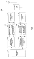
- FIG.5 is a block diagram showing a configuration of a wireless communication apparatus on a WLAN according to Embodiment 1 of the present invention.
- the present embodiment is an example of application to a wireless communication apparatus on a WLAN.
- wireless communication apparatus 100 is a wireless communication terminal, such as a cellular telephone device/PHS (Personal Handy-phone System) or a PDA that carries out wireless communication, and is provided with WLAN functions as a system that can access non-carrier local networks.
- WLAN Wireless Local Area Network
- Examples of information delivery services using non-carrier networks include low-power, short-distance, and bi-directional wireless communication schemes such as Bluetooth (registered trademark) and UWB, in addition to WLAN.
- Wireless communication apparatus 100 is comprised of antenna 101, transmission/reception changeover switch (T/R SW) 102, WLAN transmitting circuit 103, WLAN receiving circuit 104, ED (Energy Detect) value detecting circuit 105, Ack error detecting circuit 106, transmission packet interference error identifying circuit 107, interference avoidance control circuit 108, rate control circuit 109, retransmission count control circuit 110 and WLAN control circuit 111.
- T/R SW transmission/reception changeover switch
- WLAN transmitting circuit 103 Wireless Fidelity
- WLAN receiving circuit 104 Wireless communication apparatus 100 is comprised of antenna 101, transmission/reception changeover switch (T/R SW) 102, WLAN transmitting circuit 103, WLAN receiving circuit 104, ED (Energy Detect) value detecting circuit 105, Ack error detecting circuit 106, transmission packet interference error identifying circuit 107, interference avoidance control circuit 108, rate control circuit 109, retransmission count control circuit 110 and WLAN control circuit 111.
- ED Electronicgy Detect
- ED value detecting circuit 105 Ack error detecting circuit 106 and transmission packet interference error identifying circuit 107 as a whole constitute transmission packet interference error detecting circuit 120, and above-described interference avoidance control circuit 108, rate control circuit 109 and retransmission count control circuit 110 as a whole constitute interference avoiding circuit 130.
- Transmission/reception changeover switch (T/R SW) 102 switches a SW at transmission timing and reception timing.
- WLAN transmitting circuit 103 transmits signals on the WLAN.
- WLAN receiving circuit 104 receives signals on the WLAN.
- WLAN control circuit 111 controls WLAN transmitting circuit 103 and WLAN receiving circuit 104.
- ED value detecting circuit 105 measures the level (ED value) of interference waves before transmitting a packet, compares the level with an interference deciding threshold and decides that the level exceeds the threshold.
- ACK error detecting circuit 106 detects that an acknowledgment for the transmitted packet is lost.
- Transmission packet interference error identifying circuit 107 decides that a transmission packet interference error has occurred from the ED value detected in ED value detecting circuit 105 and the acknowledgment error detected in Ack error detecting circuit 106.
- interference avoidance control circuit 108 controls the transmission rate and the number of retransmissions, to avoid interference.
- Rate control circuit 109 actually changes the rate upon request from interference avoidance control circuit 108.
- Retransmission count control circuit 110 changes the retransmission count upon request from interference avoidance control circuit 108.
- the interference avoidance control by interference avoiding circuit 130 will be described later in detail in Embodiment 4 and Embodiment 5.
- the prior arts only detect whether or not interference waves are produced and do not detect whether or not a communication error has occurred due to occurrence of interference waves.
- the present embodiment decides whether or not a communication error has occurred due to interference. That is, the present interference detecting method detects whether or not a communication error has actually occurred due to occurrence of interference. Examples of this interference detecting method include interference detecting methods for three packets, namely transmission packets, received packets and beacon, and now the interference error detecting method for transmission packets will be described with the present embodiment.
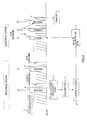
- FIG.6 illustrates the transmission packet interference error detecting method by transmission packet interference error detecting circuit 120. This interference detecting method will be referred to as an "Ack error decision method.”
- ED Electronicgy Detect
- CS carrier sensing
- ED value detecting circuit 105 measures an ED value to be detected before packet transmission and Ack error detecting circuit 106 detects an Ack response from an AP (Access Point) to a packet transmitted under a condition of excess over prescribed interference deciding threshold.
- Transmission packet interference error identifying circuit 107 decides a transmission packet error by interference when an Ack response from the AP for the transmitted packet is lost.
- the transmission packet interference error detecting method will be explained in more detail with reference to FIG.6 .
- Transmission packet interference error detecting circuit 120 of the present embodiment identifies an interference error when a packet transmitted under a condition that the measured ED value exceeds an interference deciding threshold, shows an acknowledgment error.
- WLAN control circuit 111 makes interference avoiding circuit 130 enter an interference avoiding mode (see FIG.6g ).
- interference avoidance control by interference avoiding circuit 130 will be described later in Embodiment 4 and Embodiment 5.
- interference avoiding circuit 130 upon detecting interference, interference avoiding circuit 130 performs ⁇ rate setting> whereby the transmission rate is set to a prescribed rate and ⁇ retransmission count setting> whereby the retransmission count is fixed (see FIG.6h ).
- the rate setting and retransmission count setting are performed and packet transmission (transmission 2) shown in FIG.6i is carried out according to this rate setting and retransmission count setting.
- this transmission 2 also collides with an interference period and acknowledgment to the packet transmitted is lost (see FIG.6j ).
- WLAN control circuit 111 controls WLAN transmitting circuit 103 to repeat retransmitting the relevant packet (see FIG.6k )
- retransmissions succeed after the interference period is over (see FIG.6l ), acknowledgment is received and communication is possible (see FIG.6m ).
- interference avoidance circuit 130 immediately performs interference avoidance control with the rate setting and retransmission count setting.
- wireless communication apparatus 100 is provided with transmission packet interference error detecting circuit 120 comprised of ED value detecting circuit 105 that measures an ED value before packet transmission, Ack error detecting circuit 106 that detects an acknowledgment error with respect to the transmitted packet and transmission packet interference error identifying circuit 107 and identifies an interference error when an acknowledgment error is detected from the packet transmitted under a condition that the measured ED value exceeds an interference deciding threshold, and therefore it is possible to detect that a communication error has actually occurred due to occurrence of interference.
- the prior arts are limited to only detecting whether or not interference waves are produced.
- the present embodiment can specify whether or not a communication error that occurs is an interference error, and allows handling corresponding to the communication error contents. For example, in the case of an interference error, interference avoidance control by interference avoiding circuit 130 is performed.
- interference avoiding circuit 130 when transmission packet interference error detecting circuit 120 detects interference, interference avoiding circuit 130 makes a rate setting and retransmission count setting and performs interference avoidance control, and can thereby effectively avoid interference upon receiving an influence of interference waves from an interference source such as a microwave shown in FIG.6 .
- FIG.7 is a block diagram showing a configuration of a wireless communication apparatus on a WLAN according to Embodiment 2 of the present invention.
- the same components as those in FIG.5 are assigned the same reference numerals and overlapping explanations will be omitted.
- the present embodiment is an example of application to a transmission packet interference error detecting method.
- wireless communication apparatus 200 is constructed by including antenna 101, transmission/reception changeover switch (T/R SW) 102, WLAN transmitting circuit 103, WLAN receiving circuit 104, ED value detecting circuit 105, transmission error detecting circuit 211, transmission packet interference error identifying circuit 212, interference avoidance control circuit 108, rate control circuit 109, retransmission count control circuit 110 and WLAN control circuit 111.
- T/R SW transmission/reception changeover switch
- Transmission packet interference error detecting circuit 220 is only different in that Ack error detecting circuit 106 and transmission packet interference error identifying circuit 107 of transmission packet interference error detecting circuit 120 in FIG.5 are replaced by transmission error detecting circuit 211 and transmission packet interference error identifying circuit 212.
- Transmission error detecting circuit 211 detects that a transmitted packet has not been successfully transmitted in prescribed retransmissions as a transmission error.
- Transmission packet interference error identifying circuit 212 decides that a transmission packet interference error has occurred from the ED value detected in ED value detecting circuit 105 and the transmission error detection result detected by transmission error detecting circuit 211.
- Embodiment 1 identifies an interference error when a packet transmitted under a condition that the ED value exceeds an interference deciding threshold contains an acknowledgment error.
- the present embodiment is only different in that the present embodiment identifies an interference error when a packet transmitted under a similar condition has not been successfully transmitted even in a plurality of retransmissions.
- FIG.8 illustrates a transmission packet interference error detecting method by transmission packet interference error detecting circuit 220.
- This interference error detecting method is called a "transmission error decision method.”
- an ED value detection and carrier sensing (CS) for detecting the presence of the wireless LAN communication carrier are performed.
- ED value detecting circuit 105 measures an ED value to be detected before packet transmission and transmission error detecting circuit 211 detects whether or not a packet transmitted under a condition of excess over prescribed interference deciding threshold has been successfully transmitted in prescribed retransmissions.
- Transmission packet interference error identifying circuit 212 identifies an interference error when the packet transmitted under a condition that the ED value exceeds the interference deciding threshold has not been successfully transmitted even in a plurality of retransmissions.
- the transmission packet interference error detecting method will be explained more specifically with reference to FIG.8 .
- the present invention has a feature of not only detecting the level of interference waves from the ED value but also deciding whether or not the packet transmitted under a condition that interference waves are produced has not been actually transmitted even in prescribed retransmissions and a transmission error results.
- Transmission packet interference error detecting circuit 220 of the present embodiment identifies an interference error when a transmission error occurs with a packet transmitted under a condition that the measured ED value exceeds an interference deciding threshold.
- WLAN control circuit 111 makes interference avoiding circuit 130 execute an interference avoiding mode (see FIG.8g ).
- interference avoidance control by interference avoiding circuit 130 will be described later in Embodiment 4 and Embodiment 5.
- interference avoiding circuit 130 upon detecting interference, interference avoiding circuit 130 performs ⁇ rate setting> whereby a transmission rate is set to a prescribed rate and ⁇ retransmission count setting> whereby a retransmission count is set (see FIG.8h ).
- a rate setting and retransmission count setting are performed and packet transmission (transmission 2) shown in FIG.8i is carried out according to the rate setting and retransmission count setting.
- this transmission 2 also collides with an interference period and acknowledgment to the transmitted packet is lost (see FIG. 8j ).
- WLAN control circuit 111 makes WLAN transmitting circuit 103 repeat retransmitting the relevant packet (see FIG.8k )
- retransmission succeeds after the interference period is over (see FIG.8l )
- acknowledgment is received and communication OK results (see FIG.8m ).
- the above-described acknowledgment error decision method according to Embodiment 1 is a method excelling in responsivity about an interference wave decision
- the decision based on a transmission error according to the present embodiment decides that the packet has actually resulted in an error, and is therefore a more reliable method. For example, even if an acknowledgment error occurs, communication may actually continue without errors through retransmissions. Therefore, it is preferable to adaptively select an acknowledgment error decision method that excels in responsivity or a decision method that is based on a transmission error excelling in reliability in an environment in which the WLAN is applied.
- FIG.9 is a block diagram showing a configuration of a wireless communication apparatus on a WLAN according to Embodiment 3 of the present invention.
- the same components as those in FIG.5 are assigned the same reference numerals and overlapping explanations will be omitted.
- the present embodiment is an example of application to a received packet interference error detecting method.
- wireless communication apparatus 300 is constructed by including antenna 101, transmission/reception changeover switch (T/R SW) 102, WLAN transmitting circuit 103, WLAN receiving circuit 104, noisefloor (interference wave level) valve measuring circuit 310, reception error detecting circuit 311, received packet (beacon) interference error identifying circuit 312, interference avoidance control circuit 108, rate control circuit 109, retransmission count control circuit 110 and WLAN control circuit 111.
- T/R SW transmission/reception changeover switch
- WLAN transmitting circuit 103 WLAN transmitting circuit 103
- WLAN receiving circuit 104 wireless communication apparatus 300 is constructed by including antenna 101, transmission/reception changeover switch (T/R SW) 102, WLAN transmitting circuit 103, WLAN receiving circuit 104, noisefloor (interference wave level) valve measuring circuit 310, reception error detecting circuit 311, received packet (beacon) interference error identifying circuit 312, interference avoidance control circuit 108, rate control circuit 109, retransmission count control circuit 110 and WLAN control circuit 111.
- Received packet interference error detecting circuit 320 is used in place of transmission packet interference error detecting circuit 120 in FIG.5 .
- Noisefloor (NF) value measuring circuit 310 measures the noisefloor (noise level) measured before and after a received packet.
- Reception error detecting circuit 311 identifies an error with a received packet (frame check sequence error).
- Received packet (including also a beacon) interference error identifying circuit 312 decides whether or not the received packet error is an interference error based on the noisefloor (noise level) and information reported from reception error detecting circuit 311.
- Embodiments 1 and 2 identify an interference error from a transmission packet.
- the present embodiment is an interference detecting method that detects an interference error from a received packet and beacon.
- FIG.10 illustrates a received packet interference error detecting method by received packet interference error detecting circuit 320.
- the noisefloor value of when a packet is received is measured and when a packet received in a status exceeding a prescribed interference deciding threshold contains an error, this error is identified a received packet error due to interference.
- the received packet interference error detecting method will be explained more specifically with reference to FIG.10 .
- the present invention has a feature of detecting the interference wave level from the noisefloor value and deciding whether the packet received under a condition that interference waves are produced actually contains an error.
- Received packet interference error detecting circuit 320 of the present embodiment identifies an interference error when a packet received in a status in which the noisefloor value exceeds an interference deciding threshold contains a frame check sequence error.
- WLAN control circuit 111 makes interference avoiding circuit 130 execute an interference avoiding mode (see FIG.10g ).
- interference avoidance control by interference avoiding circuit 130 will be described later in Embodiment 4 and Embodiment 5.
- interference avoiding circuit 130 upon detecting interference, interference avoiding circuit 130 performs ⁇ rate setting> for setting the transmission rate to a prescribed rate and ⁇ retransmission count setting> for setting a retransmission count (see FIG.10h ).
- Rate setting and retransmission count setting are performed based on the interference avoidance control by interference avoiding circuit 130 and packet transmission (transmission 1) shown in FIG.10i is performed according to this rate setting and retransmission count setting.
- this transmission 1 also collides with the interference period and acknowledgment for the transmitted packet is lost (see FIG.10j ).
- wireless communication apparatus 300 is comprised of noisefloor value measuring circuit 310 that measures the noise floor value of a received packet or beacon, reception error detecting circuit 311 that detects that the received packet contains a frame check sequence error and received packet (beacon) interference error identifying circuit 312, and identifies an interference error when a frame check sequence error is detected from a packet received under a condition that the measured noisefloor value exceeds an interference deciding threshold, and can thereby have effects similar to those in Embodiments 1 and 2, that is, can detect that a communication error has occurred due to occurrence of interference and identify whether or not the communication error generated is attributable to an interference error.
- the noisefloor value of a received packet is measured, but the noisefloor value of when a beacon is acquired can also be measured and similar effects can be obtained.
- a frame check sequence error of a received packet is detected as a reception error, but a reception error other than frame check sequence error or S/N value may also be detected.
- Embodiment 4 and Embodiment 5 will explain interference avoidance control for avoiding interference when the above-described interference detecting method causes interference.
- the interference avoiding circuit of the present embodiment is an example of application to an interference avoiding circuit of a wireless communication apparatus on a WLAN.
- an example of application to interference avoiding circuit 130 of the wireless communication apparatus in FIG.5 , FIG.7 or FIG.9 will be explained.
- interference avoiding circuit 130 is formed with interference avoidance control circuit 108 that controls the transmission rate and the retransmission count, rate control circuit 109 that actually changes the rate upon request from interference avoidance control circuit 108 and retransmission count control circuit 110 that changes the retransmission count upon request from interference avoidance control circuit 108.
- the present embodiment (1) stops fallback control upon detection of interference and fixes the transmission rate to a certain rate and (2) sets, upon detection of interference, a greater retransmission count than during normal communication.
- FIG.11 shows a relationship between an interference wave and the number of packet retransmissions according to interference avoiding circuit 130 of the wireless communication apparatus of the present embodiment.
- a case where a microwave is turned on (i.e. interference period) intermittently for a period of 20 msec will be taken as an example.
- a beacon has a packet length of about 1 msec.
- interference error detecting circuit 120, 220 or 320 detects interference (see FIG.5 , FIG.7 , FIG.9f)
- interference avoiding circuit 130 moves to ⁇ interference avoiding mode> (see FIG.5 , FIG.7 , FIG.9g) and interference avoidance control circuit 108 stops the fallback control on rate control circuit 109 and sets the transmission rate to a prescribed rate.
- the transmission rate is fixed to such a rate that interference can be avoided between an "ON" period (i.e. interference period) of the microwave and the next "ON" period (i.e. interference period) of the microwave.
- Rate control circuit 109 stops fallback control, fixes the transmission rate to a certain rate and thereby performs retransmission without increasing the packet length.
- FIG.11b is acknowledgment for retransmission n
- FIG.11d is acknowledgment for reception.
- interference avoidance control circuit 108 sets a greater retransmission count in retransmission count control circuit 110 than during normal operation.
- the retransmission count in normal operation is of about three to seven, but when interference is detected, the retransmission count is set to ten or more.
- retransmission n in FIG. 11a retransmission is carried out at a retransmission count that exceeds the "ON" period (i.e. interference period) of the microwave and communication thereby succeeds.
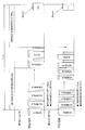
- FIG.12 is a flowchart showing interference avoidance processing by interference error avoiding circuit 130. "S” in the figure stands for each step in the flow.
- FIG.13 is a table of operation contents of an interference wave level decision and interference error decision.
- interference error detecting circuit 120, 220, 320 is monitoring a communication status and decides the interference wave level in step S2.
- an interference wave level decision when a [transmission packet] is used as shown in the table in FIG.13 , the ED value before transmission is measured to decide whether or not the measured ED value exceeds an interference deciding threshold (see Embodiments 1 and 2).
- the noisefloor value at the time of reception is measured to decide whether or not the measured noisefloor value exceeds the interference deciding threshold (see Embodiment 3).
- the above-described ED value or noisefloor value is less than the interference deciding threshold, no interference wave has occurred, and therefore the process does not move to the interference avoidance operation, but the process returns to step S1 above to continue the normal communication status.
- an interference error decision is made in step S3.
- an interference error is identified when acknowledgment from the AP to the packet transmitted under a condition that the ED value exceeds the interference deciding threshold is lost (see Embodiment 1).
- an interference error is identified when the packet transmitted under a condition that the ED value exceeds the interference deciding threshold has not been successfully transmitted in prescribed retransmissions (see Embodiment 2).
- an interference error is identified when an error is found in the packet received under a condition that the noisefloor value exceeds the interference deciding threshold. In this way, an interference error is identified when an error is found in a packet transmitted or received in an environment in which the interference wave level is such a large level that exceeds a prescribed interference deciding threshold.
- step S3 When the ED value or noisefloor value exceeds the interference deciding threshold but no error has occurred in step S3 above, there is no need to perform this interference avoidance, and therefore the normal communication status is maintained.
- the transmission rate is set to a prescribed fixed rate so that communication is possible in the gap between the interference sources (e.g., "ON" periods of microwave) in step S4 and a retransmission count that increases the retransmission count compared to the count for during normal communication is set in step S5 and this flow is finished.
- rate control circuit 109 stops fallback control and sets the transmission rate to a prescribed transmission rate.
- retransmission count control circuit 110 sets a greater retransmission count than during normal operation. For example, a retransmission count of about three to seven in normal communication is increased to ten or so.
- fallback control is stopped, the rate is set so that the packet length is fixed and more retransmissions are carried out, and retransmission prescribed so as to have an appropriate packet size for the gap between interference waves upon detection of an interference error is thereby carried out a greater number of times than normal retransmission, the hit rate of passing the gap between interference sources improves and the effect of passing the gap between the interference sources and making communication possible are anticipated.
- interference avoiding circuit 130 comprised of interference avoidance control circuit 108, rate control circuit 109 and retransmission count control circuit 110 and interference avoiding circuit 130 stops, upon detection of an interference error, fallback control that reduces the transmission rate, fixes the transmission rate to a certain rate and sets a greater retransmission count than during normal communication, and therefore communication is made possible in the gap between interference sources while carrying out retransmission with a certain fixed packet length, and it is possible to avoid interference upon receiving influences of interference waves due to interference sources such as a microwave during WLAN communication and carry out communication.
- Embodiment 4 stops fallback control upon detecting interference, fixes the transmission rate to a certain rate, sets a greater retransmission count than during normal communication, and can thereby perform interference avoidance in the gap between interference sources.
- the present embodiment is an example where a transmission rate and a retransmission count at the time of above-described interference avoidance are set according to the size of data transmitted.
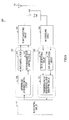
- FIG.14 is a block diagram showing a configuration of a wireless communication apparatus on a WLAN according to Embodiment 5 of the present invention.
- the same components as those in FIG.5 and FIG.9 are assigned the same reference numerals and overlapping explanations will be omitted.
- the present embodiment is an example of application to an interference error detecting method for a transmission packet and a received packet.
- wireless communication apparatus 400 is constructed by including antenna 101, transmission/reception changeover switch (T/R SW) 102, WLAN transmitting circuit 103, WLAN receiving circuit 104, ED value detecting circuit 105, Ack error detecting circuit 106, transmission packet interference error identifying circuit 107, noisefloor (interference wave level) value measuring circuit 310, reception error detecting circuit 311, received packet (beacon) interference error identifying circuit 312, packet size input circuit 431, rate/retransmission count determining circuit 432, interference avoidance control circuit 433, rate control circuit 109, retransmission count control circuit 110 and WLAN control circuit 111.
- T/R SW transmission/reception changeover switch
- ED value detecting circuit 105 Ack error detecting circuit 106, transmission packet interference error identifying circuit 107, noisefloor value measuring circuit 310, reception error detecting circuit 311 and received packet interference error identifying circuit 312 as a whole constitute packet interference error detecting circuit 420 and above-described packet size input circuit 431, rate/retransmission count determining circuit 432, interference avoidance control circuit 433, rate control circuit 109 and retransmission count control circuit 110 as a whole constitute interference avoiding circuit 430.
- Packet interference error detecting circuit 420 has a configuration including both transmission packet interference error detecting circuit 120 in FIG.5 and received packet interference error detecting circuit 320 in FIG.9 .
- Interference avoiding circuit 430 is different in that packet size input circuit 431 and rate/retransmission count determining circuit 432 are added to interference avoiding circuit 130 in FIG.5 and interference avoidance control circuit 433 has additional control of setting a transmission rate and a retransmission count according to the size of data transmitted.
- Packet size input circuit 431 inputs the size of a packet to be transmitted to rate/retransmission count determining circuit 432.
- Rate/retransmission count determining circuit 432 determines a rate/retransmission count from the inputted packet according to a prescribed table.
- FIG.15 shows an example of an interference avoidance table referred to by rate/retransmission count determining circuit 432.
- interference avoidance setting table 500 stores transmission rates A, B, C ... [Mbps] in packet sizes P(A), P(B), P(C), ... and retransmission counts R(A), R(B), R(C), ... beforehand as table values.
- the transmission rate and retransmission count corresponding to this packet size P(A) is referred to and transmission rate A [Mbps] and retransmission count R(A) are read in this case.
- FIGs.16A and B show a relationship between an interference wave and the number of packet retransmissions according to interference avoiding circuit 430 of the wireless communication apparatus of the present embodiment.
- a case where a microwave is turned on (i.e. interference period) intermittently for a period of 20 msec will be taken as an example.
- a beacon has a packet length of about 1 msec.
- the present embodiment sets the transmission rate and retransmission count at the time of interference avoidance according to the size of data to be transmitted.
- the basic operations after the settings of the transmission rate and retransmission count are similar to those in Embodiment 4.
- interference avoiding circuit 430 moves to ⁇ interference avoiding mode>.
- Packet size input circuit 431 of interference avoiding circuit 430 inputs the size of a packet to be transmitted to rate/retransmission count determining circuit 432.
- Rate/retransmission count determining circuit 432 refers to interference avoidance setting table 500 and reads transmission rates A, B, C ... [Mbps] and retransmission counts R(A), R(B), R(C), ... corresponding to the inputted size of the packet transmitted.
- FIG.16A shows a case where a size of data to be transmitted (packet size) P(A) is inputted, transmission rate A [Mbps] and retransmission count R(A) corresponding to the packet size P (A) are read and set
- FIG.16B shows a case where the size of data to be transmitted (packet size) P(C) is inputted, transmission rate C [Mbps] and retransmission count R(C) corresponding to packet size P(C) are read and set.
- Interference avoidance control circuit 433 stops fallback control on rate control circuit 109 and fixes the transmission rate to a rate set by rate/retransmission count determining circuit 432. For example, as shown in FIG.16A , in response to transmission packet size P(A) generated, the transmission rate is fixed to transmission rate A [Mbps] so as to be able to avoid interference in the gap between an "ON" period (i.e. interference period) of a microwave and the next "ON" period (i.e. interference period) of the microwave.
- the transmission rate set by rate control circuit 109 is made variable according to the size of data to be transmitted.
- transmission rate A [Mbps] and transmission rate C [Mbps] of retransmission and reception vary according to packet size P(A) and packet size P(C), but a packet length is set to such a length that makes communication possible in the gap between "ON" periods (i.e.
- the transmission packet and retransmission packet lengths become packet sizes that allow interference avoidance corresponding to the transmission data size and repeating the retransmission in FIG.16A , (b) makes it possible to pass through the gap between "ON" periods (i.e. interference period) of the microwave.
- interference avoidance control circuit 433 sets the retransmission count determined by rate/retransmission count determining circuit 432 in retransmission count control circuit 110.
- the basic value itself of the retransmission count determined by rate/retransmission count determining circuit 432 is a greater retransmission count than during normal operation and a retransmission count adjusted according to the transmission data size is set therein.
- retransmission count R (A) and retransmission count R(C) are set according to packet size P(A) and packet size P(C) respectively.
- the retransmission count is of about three to seven, but when interference is detected, retransmission counts R (A) and R(C) of at least ten or so are set. In this way, as shown by retransmission n in FIG.16A , (b), retransmission is repeated so as to exceed the "ON" period (i.e. interference period) of the microwave, and communication by retransmission thereby succeeds.
- FIG.17 is a flowchart showing interference avoidance processing by interference error avoiding circuit 430. Steps of performing the same processing as that in the flow in FIG.12 are assigned the same reference numerals.
- interference error detecting circuit 420 is monitoring a communication status and decides the interference wave level in step S2.
- an interference wave level decision when a [transmission packet] is used as shown in the table in FIG.13 , the ED value before transmitting is measured to decide whether or not the measured ED value exceeds an interference deciding threshold.
- the noisefloor value at the time of reception is measured to decide whether or not the measured noisefloor value exceeds the interference deciding threshold.
- the above-described ED value or NF value is less than the interference deciding threshold, the level of interference waves is low and it is therefore decided that no interference wave has occurred and the process returns to step S1 above.
- an interference error decision is made in step S3.
- the interference wave error decision when the [transmission packet] is used as shown in the table in FIG.13 , an interference error is identified when acknowledgment from the AP to the packet transmitted under a condition that the ED value exceeds an interference deciding threshold is lost. Alternatively, an interference error is identified when a packet transmitted under a condition that the ED value exceeds an interference deciding threshold has not been successfully transmitted in prescribed retransmissions.
- an interference error is identified when a packet received under a condition that the noisefloor value exceeds an interference deciding threshold contains an error. In this way, an interference error is identified when a packet transmitted or received under a condition that interference waves are produced contains an error.
- step S3 when it is decided that the ED value or noisefloor value exceeds the interference deciding threshold but no interference error results, communication can be continued even when interference waves are produced , and therefore a normal communication status is maintained.
- the packet size is calculated in step S11.
- the size of transmission data generated is inputted from packet size input circuit 431 and the packet size is calculated from this packet size.
- step S12 a transmission rate is set according to the calculated packet size with reference to prescribed interference avoidance setting table 500
- step S13 a retransmission count is set with reference to interference avoidance setting table 500 and this flow is finished.
- the transmission rate set with reference to interference avoidance setting table 500 is a prescribed fixed transmission rate so as to be communicable through the gap between interference sources (e.g., microwave that is turned on).
- the retransmission count set with reference to interference avoidance setting table 500 is a greater retransmission count than during normal operation.
- fallback control is stopped, a rate setting is made so as to fix the packet length, retransmission is performed a greater number of times, and when an interference error is detected, retransmission of a packet of a size prescribed for interference avoidance is performed a greater number of times than normal retransmission, and the hit rate of passing the gap between interference sources thereby improves and the effect of passing the gap between interference sources and making communication possible are anticipated.
- the present embodiment sets the transmission rate and retransmission count according to the size of a packet to be transmitted, and therefore when retransmission is performed with a certain packet length, an appropriate transmission rate and retransmission count can be set, and during WLAN communication when influences of interference waves from an interference source such as a microwave are received, the effect of further increasing the effectiveness of interference avoidance are anticipated.
- the present embodiment sets the transmission rate and retransmission count according to prescribed interference avoidance setting table 500 according to the size of a packet to be transmitted, but any method can be adopted as long as a transmission rate or retransmission count is set according to the size of data to be transmitted.
- transmission rate setting it is also possible to use the method of calculating a transmission rate so as to obtain a certain packet length from the size of a packet to be transmitted without having any table.
- wireless communication apparatus uses the terms such as “wireless communication apparatus,” “wireless LAN system,” “interference detecting method” and “interference avoidance method” but these terms are used for convenience of explanation and it goes without saying that the terms can also be “mobile terminal,” “wireless communication device,” “wireless communication control method” and “jamming elimination method” or the like.
- the type, the number and connection method of the respective circuit sections making up the above-described wireless communication apparatus are not limited to the aforementioned embodiments.
- the interference detecting method and interference avoidance method explained above can also be implemented by a program to cause this interference detesting method and interference avoidance method to function.
- This program is stored in a computer-readable recording medium.
- the wireless communication apparatus adopts a configuration including: a communication status deciding section that decides a wireless communication status; a packet error detecting section that detects an error with a transmitted or received packet; and an interference error deciding section that decides, when the wireless communication status decided in the communication status deciding section shows a predetermined interference decision condition, an interference error from an interference source when an error is detected in the packet error detecting section.
- the communication status deciding section may measure the ED value before packet transmission and the communication status deciding section may measure the level of interference waves before packet transmission.
- the communication status deciding section may measure the noisefloor value of when a packet is received and the communication status deciding section may measure the noisefloor value of when a beacon is received and further the communication status deciding section may measure an S/N when a received packet is acquired.
- the packet error detecting section may detect an acknowledgment error with respect to a transmitted packet, the packet error detecting section may detect that a transmitted packet cannot be retransmitted in a predetermined number of retransmissions, and further the packet error detecting section may detect that a received packet contains a frame check sequence error.
- the wireless communication apparatus of the present invention is a wireless communication apparatus that performs fallback control to reduce transmission rate when a communication error occurs and adopts a configuration including an interference avoidance control section that stops, when an interference error is detected, the fallback control, fixes the transmission rate to a certain rate and increases the number of retransmissions compared to the count for during normal communication.
- the wireless communication apparatus of the present invention is a wireless communication apparatus that performs rate control that increases a transmission rate when a communication error is corrected, and adopts a configuration including an interference avoidance control section that stops, when an interference error is detected, fallback control, fixes a transmission rate to a certain rate and increases the number of retransmissions compared to the count for during normal communication.
- the interference avoidance control section may set the transmission rate in a packet size to pass the gap between interference periods from a specific interference source, the interference avoidance control section may set the retransmission count to reach the gap between interference periods from a specific interference source and further the interference avoidance control section may set the transmission rate and/or the retransmission count according to the size of a packet transmitted.
- the wireless communication apparatus of the present invention further includes an interference detecting section that detects interference errors, and this interference detecting section has: a communication status deciding section that decides a wireless communication status; a packet error detecting section that detects an error with a transmitted or received packet; and an interference error deciding section that decides, when the wireless communication status decided in the communication status deciding section shows a predetermined interference decision condition, an interference error from an interference source when an error is detected in the packet error detecting section.
- the wireless LAN system of the present invention is a wireless LAN system that connects a plurality of wireless communication apparatuses via a wireless network and adopts a configuration in which the wireless communication apparatuses are each one of the wireless communication apparatuses described above.
- the interference detecting method of the present invention includes the steps of: measuring an energy detect value before packet transmission; detecting an acknowledgment error with respect to a transmitted packet; and identifying an interference error when the acknowledgment error is detected with respect to the packet transmitted under a condition that the measured energy detect value exceeds an interference deciding threshold.
- the interference detecting method of the present invention includes the steps of: measuring an energy detect value before packet transmission; detecting a transmission error that a transmitted packet cannot be retransmitted in a predetermined number of retransmissions; and identifying an interference error when the transmission error is detected from the packet transmitted under a condition that the measured energy detect value exceeds an interference deciding threshold.
- the interference detecting method of the present invention includes the steps of: measuring the noisefloor value of when a packet is received; detecting a reception error with the received packet including a frame check sequence error; and identifying an interference error when the reception error is detected from the packet received under a condition that the measured noisefloor value exceeds an interference deciding threshold.
- the interference detecting method of the present invention includes: measuring the noisefloor value of when a beacon is received; detecting a reception error with a received packet including a frame check sequence error; and identifying an interference error when the reception error is detected with the packet received under a condition that the measured noisefloor value exceeds an interference deciding threshold.
- the interference avoidance method of the present invention includes the steps of: stopping, when an interference error is detected, fallback control to reduce transmission rate and fixing the transmission rate to a certain rate; and increasing the number of retransmissions compared to the count for during normal communication.
- the transmission rate in a packet size to pass the gap between interference periods from a specific interference source may be set for the gap.
- the retransmission count that reaches a gap between interference periods from a specific interference source may be set for the gap.
- the transmission rate may be set according to the size of a packet transmitted and in the retransmission count step, the retransmission count may be set according to the size of a packet transmitted.
- the interference avoidance method of the present invention further includes a step of detecting interference errors, the interference error detecting step comprises the steps of: measuring an energy detect value before packet transmission; detecting an acknowledgment error with respect to a transmitted packet; and identifying an interference error when the acknowledgment error is detected with respect to the packet transmitted under a condition that the measured energy detect value exceeds an interference deciding threshold.
- the wireless communication apparatus, wireless LAN system, interference detecting method and interference avoidance method according to the present invention have the effect of detecting interference and avoiding the interference and are especially effective for a wireless communication apparatus making up a wireless LAN system that connects a plurality of wireless communication apparatuses via a wireless network and a wireless communication control method.
Landscapes
- Engineering & Computer Science (AREA)
- Computer Networks & Wireless Communication (AREA)
- Signal Processing (AREA)
- Quality & Reliability (AREA)
- Physics & Mathematics (AREA)
- Electromagnetism (AREA)
- Mobile Radio Communication Systems (AREA)
- Detection And Prevention Of Errors In Transmission (AREA)
- Communication Control (AREA)
Applications Claiming Priority (2)
| Application Number | Priority Date | Filing Date | Title |
|---|---|---|---|
| JP2006205395 | 2006-07-27 | ||
| PCT/JP2007/050694 WO2008012954A1 (fr) | 2006-07-27 | 2007-01-18 | Appareil de communication sans fil, système lan sans fil, procédé de détection d'interférence, et procédé d'évitement d'interférence |
Publications (2)
| Publication Number | Publication Date |
|---|---|
| EP2056528A1 true EP2056528A1 (fr) | 2009-05-06 |
| EP2056528A4 EP2056528A4 (fr) | 2017-03-01 |
Family
ID=38981270
Family Applications (1)
| Application Number | Title | Priority Date | Filing Date |
|---|---|---|---|
| EP07706998.7A Withdrawn EP2056528A4 (fr) | 2006-07-27 | 2007-01-18 | Appareil de communication sans fil, système lan sans fil, procédé de détection d'interférence, et procédé d'évitement d'interférence |
Country Status (4)
| Country | Link |
|---|---|
| US (1) | US8255756B2 (fr) |
| EP (1) | EP2056528A4 (fr) |
| JP (3) | JP5351313B2 (fr) |
| WO (1) | WO2008012954A1 (fr) |
Cited By (3)
| Publication number | Priority date | Publication date | Assignee | Title |
|---|---|---|---|---|
| WO2014015266A3 (fr) * | 2012-07-19 | 2014-03-20 | Qualcomm Incorporated | Multiplexage d'ue ayant des configurations tdd différentes et certaines techniques de limitation de brouillage d'ue à ue et de station de base à station de base |
| US9585156B2 (en) | 2011-11-14 | 2017-02-28 | Qualcomm Incorporated | Supporting different LTE-TDD configurations in neighboring regions and/or adjacent carriers |
| EP2495896A4 (fr) * | 2009-10-28 | 2017-11-29 | Panasonic Corporation | Dispositif de communication sans fil |
Families Citing this family (21)
| Publication number | Priority date | Publication date | Assignee | Title |
|---|---|---|---|---|
| DE10350063A1 (de) * | 2003-10-27 | 2005-05-25 | Rohde & Schwarz Gmbh & Co. Kg | Verfahren und Vorrichtung zur Messung von Funkstörpegeln mit Frequenznachführung |
| US8040837B2 (en) * | 2005-06-10 | 2011-10-18 | Panasonic Corporation | Wireless communication apparatus and wireless communication method |
| EP1990954B1 (fr) * | 2006-03-02 | 2018-06-27 | Panasonic Intellectual Property Management Co., Ltd. | Dispositif de transmission, système de communication sans fil et procédé de transmission |
| JP4901681B2 (ja) * | 2007-10-05 | 2012-03-21 | 株式会社東芝 | 無線通信装置及び無線通信方法 |
| KR101102091B1 (ko) * | 2010-01-29 | 2012-01-04 | 주식회사 팬택 | 통신장치 및 통신장치의 간섭 회피 방법 |
| US9544096B2 (en) | 2010-06-18 | 2017-01-10 | Thomson Licensing | Packet retransmission method in a wireless transmitter |
| US10504360B2 (en) | 2011-04-08 | 2019-12-10 | Ross Gilson | Remote control interference avoidance |
| JP5939262B2 (ja) | 2011-12-12 | 2016-06-22 | 富士通株式会社 | 送信制御方法、ノードおよび送信制御プログラム |
| CN104685832B (zh) | 2012-10-31 | 2019-06-14 | 富士通株式会社 | 通信控制方法、网络系统以及通信装置 |
| EP2852203B1 (fr) | 2013-06-28 | 2017-08-16 | Panasonic Corporation | Procédé de détermination de canal et appareil de communication sans fil |
| US9083647B2 (en) * | 2013-11-22 | 2015-07-14 | Litepoint Corporation | System and method for dynamic signal interference detection during testing of a data packet signal transceiver |
| JP6292505B2 (ja) * | 2014-01-23 | 2018-03-14 | パナソニックIpマネジメント株式会社 | 無線通信方法、無線通信システム、通信装置 |
| JP6218639B2 (ja) * | 2014-02-27 | 2017-10-25 | シャープ株式会社 | 無線通信システム及び無線通信装置 |
| JP2016036111A (ja) * | 2014-08-04 | 2016-03-17 | 株式会社東芝 | 無線通信装置 |
| JP6300210B2 (ja) | 2014-10-28 | 2018-03-28 | パナソニックIpマネジメント株式会社 | 無線通信装置 |
| US10211899B1 (en) * | 2015-09-17 | 2019-02-19 | Sprint Spectrum L.P. | Systems and methods for detecting interference at an access node |
| JP6334494B2 (ja) * | 2015-10-13 | 2018-05-30 | 株式会社東芝 | 無線通信装置および無線通信方法 |
| JP6460959B2 (ja) * | 2015-11-06 | 2019-01-30 | 日本電信電話株式会社 | デジタル情報伝送システムおよびデジタル情報伝送方法 |
| TWI631832B (zh) * | 2016-08-06 | 2018-08-01 | 新加坡商雲網科技新加坡有限公司 | 一種可感知干擾源的系統及方法 |
| WO2018151121A1 (fr) * | 2017-02-17 | 2018-08-23 | 日本電気株式会社 | Dispositif de communication, et procédé de communication |
| CN107155208A (zh) * | 2017-05-22 | 2017-09-12 | 燕山大学 | 基于信道优先级排序的ZigBee抗干扰方法 |
Family Cites Families (32)
| Publication number | Priority date | Publication date | Assignee | Title |
|---|---|---|---|---|
| JPH0514290A (ja) | 1991-07-08 | 1993-01-22 | Nippon Telegr & Teleph Corp <Ntt> | 干渉検出方式 |
| JPH09116484A (ja) * | 1995-10-17 | 1997-05-02 | Nippon Telegr & Teleph Corp <Ntt> | 無線パケットチャネル切替方法 |
| JPH09200846A (ja) * | 1996-01-12 | 1997-07-31 | Matsushita Electric Ind Co Ltd | 移動通信システム |
| US5701311A (en) * | 1996-02-08 | 1997-12-23 | Motorola, Inc. | Redundant acknowledgements for packetized data in noisy links and method thereof |
| US5889772A (en) * | 1997-04-17 | 1999-03-30 | Advanced Micro Devices, Inc. | System and method for monitoring performance of wireless LAN and dynamically adjusting its operating parameters |
| JPH11205216A (ja) * | 1998-01-07 | 1999-07-30 | Matsushita Electric Ind Co Ltd | パケット通信方法およびパケット通信装置 |
| EP1041771B1 (fr) * | 1999-04-01 | 2009-06-17 | Lucent Technologies Inc. | Contrôle amélioré du débit de données pour communication sans fil |
| JP2001094574A (ja) * | 1999-09-24 | 2001-04-06 | Nippon Telegr & Teleph Corp <Ntt> | 無線lanシステム |
| EP1119153A1 (fr) * | 2000-01-19 | 2001-07-25 | Lucent Technologies Inc. | Procédé et dispositif pour une réduction robuste de débit dans un système de communication de données |
| JP4348498B2 (ja) | 2000-07-17 | 2009-10-21 | ソニー株式会社 | 無線通信機器 |
| US6643322B1 (en) * | 2000-09-20 | 2003-11-04 | Aperto Networks, Inc. | Dynamic wireless link adaptation |
| US6922557B2 (en) * | 2000-10-18 | 2005-07-26 | Psion Teklogix Inc. | Wireless communication system |
| CN1146261C (zh) * | 2000-10-27 | 2004-04-14 | 清华大学 | 一种在衰落信道中重传丢失分组的方法 |
| US7103817B1 (en) * | 2001-04-19 | 2006-09-05 | Cisco Technology, Inc. | Method and system for dynamically controlling frame retransmissions in a wireless network |
| DE60107207T2 (de) | 2001-05-08 | 2005-12-01 | Lucent Technologies Inc. | Drahtloses lokales Netz mit dynamischer Frequenzwahl |
| US6915477B2 (en) * | 2001-12-28 | 2005-07-05 | Lucent Technologies Inc. | Delay sensitive adaptive quality control loop for rate adaptation |
| KR100850989B1 (ko) * | 2002-01-05 | 2008-08-12 | 엘지전자 주식회사 | 자동 반복 요청(arq)시스템에서응답정보(ack/nack)신호에 대한 전력제어 방법 |
| JP4198921B2 (ja) * | 2002-02-28 | 2008-12-17 | 株式会社エヌ・ティ・ティ・ドコモ | 適応無線パラメータ制御方法、QoS制御装置、基地局及び無線通信システム |
| US6996763B2 (en) * | 2003-01-10 | 2006-02-07 | Qualcomm Incorporated | Operation of a forward link acknowledgement channel for the reverse link data |
| JP4335060B2 (ja) * | 2003-05-21 | 2009-09-30 | シャープ株式会社 | 無線通信装置、送信機、受信機、無線通信システム、ワイヤレスavシステム、無線伝送方法並びに動作制御プログラム及びそのプログラムを記録した記録媒体 |
| JP4079832B2 (ja) | 2003-05-29 | 2008-04-23 | 株式会社東芝 | 電波干渉解消方法,およびステーション装置 |
| JP2005252608A (ja) * | 2004-03-03 | 2005-09-15 | Nippon Telegr & Teleph Corp <Ntt> | 無線特性情報を基にした送信方式選択方法および装置、ならびにそのプログラムと記録媒体 |
| JP4354319B2 (ja) | 2004-03-26 | 2009-10-28 | Tdk株式会社 | 無線通信装置の制御方法及び無線通信装置 |
| EP1735935B1 (fr) * | 2004-04-05 | 2008-03-12 | Wireless Audio IP B.V. | Systeme et procede de transmission audio sans fil, a attribution de creneau dynamique |
| JP2005333510A (ja) | 2004-05-21 | 2005-12-02 | Toshiba Corp | 無線通信制御装置およびその制御方法 |
| EP1787418A1 (fr) * | 2004-08-30 | 2007-05-23 | Koninklijke Philips Electronics N.V. | Procede et systeme d'adaptation de liaison dans des reseaux sans fil |
| JP2008512025A (ja) * | 2004-08-30 | 2008-04-17 | コーニンクレッカ フィリップス エレクトロニクス エヌ ヴィ | 無線網におけるエラー識別のための方法及びシステム |
| KR100570825B1 (ko) | 2004-09-30 | 2006-04-12 | 삼성전자주식회사 | 무선 랜 시스템에서 인접 bss간의 간섭 감지 장치 및방법 |
| JP4434920B2 (ja) | 2004-10-26 | 2010-03-17 | 株式会社東芝 | 無線通信装置および無線通信方法 |
| JP2006205395A (ja) | 2005-01-25 | 2006-08-10 | Bridgestone Corp | 高分子・金属複合体 |
| US20060221847A1 (en) * | 2005-03-29 | 2006-10-05 | Dacosta Behram M | Method and apparatus for selecting transmission modulation rates in wireless devices for A/V streaming applications |
| US20060268924A1 (en) * | 2005-04-01 | 2006-11-30 | Interdigital Technology Corporation | Method and apparatus for dynamically adjusting a deferred transmission level and a transmission power level in a wireless communication system |
-
2007
- 2007-01-18 EP EP07706998.7A patent/EP2056528A4/fr not_active Withdrawn
- 2007-01-18 US US12/375,383 patent/US8255756B2/en active Active
- 2007-01-18 WO PCT/JP2007/050694 patent/WO2008012954A1/fr active Application Filing
-
2012
- 2012-07-12 JP JP2012156505A patent/JP5351313B2/ja active Active
-
2013
- 2013-08-22 JP JP2013172314A patent/JP5521098B2/ja not_active Expired - Fee Related
-
2014
- 2014-04-04 JP JP2014077715A patent/JP2014161056A/ja active Pending
Non-Patent Citations (1)
| Title |
|---|
| See references of WO2008012954A1 * |
Cited By (9)
| Publication number | Priority date | Publication date | Assignee | Title |
|---|---|---|---|---|
| EP2495896A4 (fr) * | 2009-10-28 | 2017-11-29 | Panasonic Corporation | Dispositif de communication sans fil |
| EP3399682A1 (fr) * | 2009-10-28 | 2018-11-07 | Panasonic Corporation | Dispositif de communication sans fil |
| US9585156B2 (en) | 2011-11-14 | 2017-02-28 | Qualcomm Incorporated | Supporting different LTE-TDD configurations in neighboring regions and/or adjacent carriers |
| WO2014015266A3 (fr) * | 2012-07-19 | 2014-03-20 | Qualcomm Incorporated | Multiplexage d'ue ayant des configurations tdd différentes et certaines techniques de limitation de brouillage d'ue à ue et de station de base à station de base |
| CN104488206A (zh) * | 2012-07-19 | 2015-04-01 | 高通股份有限公司 | 复用具有不同tdd配置的ue以及用于减轻ue对ue和基站对基站的干扰的一些技术 |
| EP3051730A1 (fr) * | 2012-07-19 | 2016-08-03 | Qualcomm Incorporated | Multiplexage d'ue avec différentes configurations de tdd et certaines techniques pour atténuer les interférences ue-à-ue les interférences station de base-à-station de base |
| US9930678B2 (en) | 2012-07-19 | 2018-03-27 | Qualcomm Incorporated | Multiplexing UEs with different TDD configurations and some techniques to mitigate UE-to-UE and base station-to-base station interference |
| CN104488206B (zh) * | 2012-07-19 | 2019-06-11 | 高通股份有限公司 | 复用具有不同tdd配置的ue以及用于减轻ue对ue和基站对基站的干扰的一些技术 |
| US10602525B2 (en) | 2012-07-19 | 2020-03-24 | Qualcomm Incorporated | Multiplexing UES with different TDD configurations and some techniques to mitigate UE-to-UE and base station-to-base station interference |
Also Published As
| Publication number | Publication date |
|---|---|
| EP2056528A4 (fr) | 2017-03-01 |
| US20100037124A1 (en) | 2010-02-11 |
| JP5521098B2 (ja) | 2014-06-11 |
| JP5351313B2 (ja) | 2013-11-27 |
| JP2014161056A (ja) | 2014-09-04 |
| JP2013240112A (ja) | 2013-11-28 |
| WO2008012954A1 (fr) | 2008-01-31 |
| JP2012235506A (ja) | 2012-11-29 |
| US8255756B2 (en) | 2012-08-28 |
Similar Documents
| Publication | Publication Date | Title |
|---|---|---|
| US8255756B2 (en) | Wireless communication apparatus, wireless LAN system, interference detecting method, and interference avoidance method | |
| US10588152B2 (en) | Access point (AP) controlled uplink RTS/CTS configuration and disablement | |
| US8351864B2 (en) | Wireless terminal and retransmission method | |
| CN102292937B (zh) | 减少运作于相邻频带中的两个通信系统之间干扰的方法 | |
| EP1832050B1 (fr) | Procede destine a reduire l'interference mutuelle entre des abonnes de reseau dans des reseaux de radiocommunication | |
| US8102939B2 (en) | Link adaptation | |
| JP5044320B2 (ja) | 無線通信装置及び無線lanシステム | |
| MXPA04007545A (es) | Minimizacion de interferencia a traves de multiplexion de division de tiempo de transmisiones ieee 802.11 y cdma. | |
| US8644269B2 (en) | Adaptive transmissions in wireless networks | |
| JP5852128B2 (ja) | バースト的ノイズ環境に対する通信技術 | |
| WO2009113137A1 (fr) | Appareil de communication sans fil | |
| US20150003344A1 (en) | Channel determination method and wireless communication apparatus | |
| KR20070047316A (ko) | 무선 네트워크에서 에러 구별 방법 및 시스템 | |
| JP2003163652A (ja) | 無線通信装置および無線通信方法 | |
| EP2154926A1 (fr) | Procédé et appareil pour fournir un paramètre d'accès à un canal | |
| US20160037500A1 (en) | Method and apparatus for controlling transmission rate of physical layer | |
| KR20150130445A (ko) | 짧은 간섭 버스트의 영향을 완화하기 위한 방법 및 장치 | |
| KR20080098872A (ko) | 다중 안테나 시스템의 스펙트럼 검출 장치 |
Legal Events
| Date | Code | Title | Description |
|---|---|---|---|
| PUAI | Public reference made under article 153(3) epc to a published international application that has entered the european phase |
Free format text: ORIGINAL CODE: 0009012 |
|
| 17P | Request for examination filed |
Effective date: 20090127 |
|
| AK | Designated contracting states |
Kind code of ref document: A1 Designated state(s): AT BE BG CH CY CZ DE DK EE ES FI FR GB GR HU IE IS IT LI LT LU LV MC NL PL PT RO SE SI SK TR |
|
| AX | Request for extension of the european patent |
Extension state: AL BA HR MK RS |
|
| RBV | Designated contracting states (corrected) |
Designated state(s): DE FR GB |
|
| DAX | Request for extension of the european patent (deleted) | ||
| RA4 | Supplementary search report drawn up and despatched (corrected) |
Effective date: 20170130 |
|
| RIC1 | Information provided on ipc code assigned before grant |
Ipc: H04B 17/345 20150101ALI20170120BHEP Ipc: H04L 1/00 20060101AFI20170120BHEP Ipc: H04L 1/18 20060101ALI20170120BHEP |
|
| STAA | Information on the status of an ep patent application or granted ep patent |
Free format text: STATUS: EXAMINATION IS IN PROGRESS |
|
| 17Q | First examination report despatched |
Effective date: 20180302 |
|
| STAA | Information on the status of an ep patent application or granted ep patent |
Free format text: STATUS: THE APPLICATION HAS BEEN WITHDRAWN |
|
| 18W | Application withdrawn |
Effective date: 20180629 |