EP2045170B1 - Structure avant pour automobile - Google Patents
Structure avant pour automobile Download PDFInfo
- Publication number
- EP2045170B1 EP2045170B1 EP08017300.8A EP08017300A EP2045170B1 EP 2045170 B1 EP2045170 B1 EP 2045170B1 EP 08017300 A EP08017300 A EP 08017300A EP 2045170 B1 EP2045170 B1 EP 2045170B1
- Authority
- EP
- European Patent Office
- Prior art keywords
- automobile
- shroud panel
- panel
- reinforcing
- shroud
- Prior art date
- Legal status (The legal status is an assumption and is not a legal conclusion. Google has not performed a legal analysis and makes no representation as to the accuracy of the status listed.)
- Expired - Fee Related
Links
Images


Classifications
-
- B—PERFORMING OPERATIONS; TRANSPORTING
- B62—LAND VEHICLES FOR TRAVELLING OTHERWISE THAN ON RAILS
- B62D—MOTOR VEHICLES; TRAILERS
- B62D25/00—Superstructure or monocoque structure sub-units; Parts or details thereof not otherwise provided for
- B62D25/08—Front or rear portions
- B62D25/082—Engine compartments
- B62D25/084—Radiator supports
-
- B—PERFORMING OPERATIONS; TRANSPORTING
- B62—LAND VEHICLES FOR TRAVELLING OTHERWISE THAN ON RAILS
- B62D—MOTOR VEHICLES; TRAILERS
- B62D21/00—Understructures, i.e. chassis frame on which a vehicle body may be mounted
- B62D21/15—Understructures, i.e. chassis frame on which a vehicle body may be mounted having impact absorbing means, e.g. a frame designed to permanently or temporarily change shape or dimension upon impact with another body
- B62D21/152—Front or rear frames
-
- B—PERFORMING OPERATIONS; TRANSPORTING
- B62—LAND VEHICLES FOR TRAVELLING OTHERWISE THAN ON RAILS
- B62D—MOTOR VEHICLES; TRAILERS
- B62D29/00—Superstructures, understructures, or sub-units thereof, characterised by the material thereof
- B62D29/001—Superstructures, understructures, or sub-units thereof, characterised by the material thereof characterised by combining metal and synthetic material
- B62D29/002—Superstructures, understructures, or sub-units thereof, characterised by the material thereof characterised by combining metal and synthetic material a foamable synthetic material or metal being added in situ
-
- B—PERFORMING OPERATIONS; TRANSPORTING
- B62—LAND VEHICLES FOR TRAVELLING OTHERWISE THAN ON RAILS
- B62D—MOTOR VEHICLES; TRAILERS
- B62D29/00—Superstructures, understructures, or sub-units thereof, characterised by the material thereof
- B62D29/04—Superstructures, understructures, or sub-units thereof, characterised by the material thereof predominantly of synthetic material
- B62D29/041—Understructures
Definitions
- the present invention relates to front end structures for automobiles and particularly relates to a front end structure for an automobile including a resin-made shroud panel supporting a heat exchanger, such as a radiator or the like.
- the resin-made shroud panel which has insufficient rigidity, may support a bonnet and the like insufficiently.
- a metal-made reinforcing member is integrally formed with an upper member extending in the car width direction in the upper part of the shroud panel to obtain a resin-made shroud panel of which upper part has rigidity equivalent to a metal-made one, as disclosed in US Patent No. 6216810 .
- the upper part of such the shroud panel is fastened and fixed to apron rein members above the engine compartment, so that an impact load from the front at head-on collision of the automobile is transmitted from the shroud panel to the apron rein members to thus be distributed, thereby enhancing the safety performance at collision of the automobile.
- a structure may be employed in which the supporting rigidity of the shroud panel is lowered so that the shroud panel is allowed to retreat as a whole at light collision together with the front bumper.
- Post-published EP 1 860 020 A1 discloses a front side of an automobile which is deformable in case of a collision and comprises support for a radiator as well as means for fixing the support on a chassis of the automobile.
- the present invention has been made in view of the foregoing and has its object of reducing repair cost by ensuring load distribution performance to a car body at heavy collision and preventing the heat exchanger and the shroud panel from being broken at light collision as far as possible in a front end structure for an automobile including a resin-made shroud panel supporting a heat exchanger.
- the present invention provides a front end structure for an automobile which includes: a resin-made shroud panel for supporting a heat exchanger which includes: an upper part extending in a car width direction; a lower part extending in the car width direction; and two side parts extending in a vertical direction to connect the upper part and the lower part; a front bumper including a bumper beam extending in the car width direction on an automobile front side of the shroud panel; a panel support part supporting the shroud panel against car body members; and a rearward movement allowing part which allows the heat exchanger to move rearward of the automobile relative to the panel support part when an impact load works on the shroud panel from front of the automobile, wherein the panel support part extends in the car width direction above the shroud panel, and the rearward movement allowing part fixes the upper part of the shroud panel to the panel support part and allows, when the impact load works on the shroud panel from the front of the automobile, the upper part to separate from the panel support part.
- the front bumper (the bumper beam) retreats upon head-on collision of the automobile so that the impact load works on the shroud panel.
- the rearward movement allowing part allows the heat exchanger to move rearward relative to the panel support part to prevent interference of the heat exchanger with the bumper beam.
- joint of the panel support part to, for example, the left and right front side frames and the apron rein member leads to distribution and transmission of the impact load working on the right and left side frames to the apron rein members through the panel support part.
- the panel support part extends in the car width direction above the shroud panel, and the rearward movement allowing part fixes the upper part of the shroud panel to the panel support part and allows, when the impact load works on the shroud panel from the front of the automobile, the upper part to separate from the panel support part.
- the upper part fixed to the panel support part separates from the panel support part upon light collision to allow the shroud panel to retreat readily, thereby preventing interference of the shroud panel and the heat exchanger with the bumper beam.
- the panel support part preferably includes: right and left side members respectively including rear end parts fixed to front end parts of respective right and left apron rein members as two of the car body members and front end parts located above front end parts of respective right and left front side frames as two of the car body members; right and left vertical members respectively including upper end parts fixed to the front end parts of the respective right and left side members and lower end parts fixed to the front end parts of the respective right and left front side frame; and a center member extending in the car width direction to connect the light and left side members, the center member being detachably fastened and fixed to the right and left side members.
- the shroud panel can be mounted from above of the automobile with the center member taken off. Accordingly, even though the panel support part is present above the shroud panel, the degree of freedom of workability in automobile assembling is enhanced.
- the center member part is preferably capable of being fixed provisionally to an upper face of the upper part of the shroud panel before being mounted to the automobile.
- the side parts of the shroud panel are fixed to the bumper beam.
- the shroud panel retreats concurrently with retreat of the front bumper upon head-on collision of the automobile.
- the heat exchanger supported by the shroud panel does not interfere with the bumper beam to prevent definitely the heat exchanger from being broken. Hence, reduction in repair cost can be contemplated.
- the panel support part includes a main body in a substantially reverse U shape in section along a longitudinal direction of the automobile and front and rear flanges formed at sides in the longitudinal direction of the automobile of the main body; and the rearward movement allowing part includes a joint member for fastening and fixing the upper part of the shroud panel to at least one of the flanges.
- the shroud panel can be fastened and fixed to the panel support part with no lowering of the load transmission performance of the panel support part at heavy collision invited.
- the joint member fastens and fixes the upper part of the shroud panel to the rear flange; a notch which is opened to rear of the automobile and through which the joint member is inserted is formed at a joint part by the joint member in the rear flange; and the rearward movement allowing part allows the upper part of the shroud panel to separate from the panel support part by separating the joint member from the notch when the impact load works on the shroud panel from the front of the automobile.
- the shroud panel can separate from the panel support part through the notch when the impact load works on the shroud panel. Accordingly, such a simple structure with the notch formed leads to easy separation of the shroud panel.
- the joint member fastens and fixes the upper part of the shroud panel to the front flange; a notch which is opened to the front of the automobile and through which the joint member is inserted is formed at a joint part by the joint member in the upper part of the shroud panel; and the rearward movement allowing part allows the upper part of the shroud panel to separate from the panel support part by separating the joint member from the notch when the impact load works on the shroud panel from the front of the automobile.
- a pocket part for accommodating a bonnet locking mechanism locking a bonnet of the automobile in the panel support part.
- a fixing flange is formed in a lower part of the pocket part, the fixing flange being fixed to the upper part of the shroud panel and capable of being released from the fixing when the impact load works on the shroud panel from the front of the automobile.
- the supporting rigidity of the pocket part is increased, and the supporting rigidity of the bonnet locking mechanism is also increased by using the shroud panel.
- the fixing flange is released from being fixed, which inhibits no retreat of the shroud panel.
- crash boxes are provided at the front ends of right and left front side frames of the automobile; the bumper beam is mounted to the right and left front side frames through the crash boxes; and the shroud panel is overlapped with the crash boxes when viewed from a side of the automobile.
- the shroud panel can retreat rearward definitely when the crash boxes are buckled and deformed upon head-on collision of the automobile. This further promotes retreat of the shroud panel at collision.
- the shroud panel can retreat at collision further definitely, thereby contemplating protection of the heat exchanger. exchanger.
- the panel support part is composed of a reinforcing part integrally formed with the shroud panel and including a metal-made reinforcement; and the shroud panel includes: a heat exchanger support part including a front end located ahead of the reinforcing part and supporting the heat exchanger; and a fragile part as the rearward movement allowing part which is formed at a boundary part between the reinforcing part and the heat exchanger support part, the fragile part allowing the heat exchanger support part and the heat exchanger to move rearward of the automobile relative to the reinforcing part when the impact load works on the heat exchanger support part of the shroud panel from the front of the automobile.
- the front bumper retreats upon head-on collision of the automobile to cause the impact load to work on the heat exchanger support part.
- deformation or the like of the fragile part causes the heat exchanger support part to shift relative to the reinforcing part, which causes the heat exchanger support part and the heat exchanger to retreat, thereby preventing interference with the bumper beam.
- the impact load also works on the reinforcing part to be distributed and transmitted to the car body members through the reinforcing part.
- the fragile part forms a thin part or a slit part at the boundary part between the reinforcing part and the heat exchanger support part.
- the fragile part is broken when the heat exchanger support part receives the impact load to cause the heat exchanger support part and the heat exchanger to shift rearward relative to the reinforcing part. Further, the fragile part can be formed simultaneously with formation of the resin-made shroud panel. Thus, the heat exchanger support part is allowed to retreat readily at head-on collision of the automobile, and no lowering of the productivity of the shroud panel is invited.
- the fragile part may be composed of a rubber member at the boundary part between the reinforcing part and the heat exchanger support part.
- the fragile part is elastically deformed when the heat exchanger support part receives the impact load to cause the heat exchanger support part and the heat exchanger to shift rearward relative to the reinforcing part.
- This retreat of the heat exchanger support part and the heat exchanger involves no breakage of the shroud panel.
- light collision necessitates no replacement of not only the heat exchanger but also the shroud panel, thereby contemplating reduction in repair cost.
- the reinforcing part is continuously formed from the upper part to the side parts of the shroud panel; the right and left side parts of the reinforcing part at the upper part are fixed to right and left apron rein members as two of the car body members, respectively; and the reinforcing member at the side parts is fixed to corresponding right and left front side frames as two of the car body members.
- the impact load at heavy collision which works on the right and left front side frames through the bumper beam, can be distributed and transmitted to the apron rein members through the reinforcing part.
- load distribution at heavy collision can be performed appropriately on the car body members arranged thereabove and therebelow to increase safety performance at collision of the automobile.
- the reinforcing part is formed in a frame-like shape at the upper part, the lower part, and the side parts.
- the reinforcing part at the lower part is preferably fixed to a suspension cross member, as one of the car body members, supporting a suspension device.
- the above arrangement fixes the position of the reinforcing part at the lower part to cause the heat exchanger support part to shift relative to the reinforcing part further definitely at light collision.
- the impact load at heavy collision can be transmitted to the suspension cross member through the lower part of the reinforcing part to contemplate further distribution of the impact load.
- the protection performance for the heat exchanger at light collision and the load distribution performance at heavy collision can be enhanced further.
- a bonnet locking mechanism for locking a bonnet of the automobile is provided at the reinforcing part at the upper part.
- This arrangement prevents the bonnet locking mechanism from retreating even when the heat exchanger support part retreats upon head-on collision of the automobile. Accordingly, the heat exchanger is prevented from being broken at collision while the bonnet supporting rigidity of the bonnet locking mechanism at collision can be increased.
- the heat exchanger support part includes an upper frame part extending in the car width direction, a lower frame part extending in the car width direction, and side frame parts extending in a vertical direction to connect the upper frame part and the lower flame part, the side frame parts being fixed to the bumper beam.
- the frame-like heat exchanger support part retreats definitely accompanied by retreat of the front bumper (the bumper beam) at head-on collision of the automobile. Accordingly, the heat exchanger supported by the heat exchanger support part never interfere with the bumper beam at collision to prevent the heat exchanger from being broken. Thus, the heat exchanger is prevented definitely from being broken to contemplate reduction in repair cost.
- crash boxes are provided at front end parts of right and left front side frames of the automobile; the bumper beam is mounted to the right and left front side frames through the crash boxes; and the reinforcing part is fixed to members as two of the car body members which are located on an automobile rear side of the crash boxes.
- the reinforcing part can be fixed firmly to the car body members without inviting influence of the crash boxes which are buckled and deformed upon head-on collision of the automobile. Accordingly, the reinforcing part will not shift at light collision, and therefore, relative shifts can be caused between the reinforcing part and the heat exchanger support part to cause the fragile part to be deformed or so definitely. In addition, the impact load at heavy collision can be transmitted appropriately to the car body members, thereby enhancing the load distribution performance.
- FIG. 1 is a front view of an automobile employing a front end structure in accordance with Embodiment 1 of the present invention
- FIG. 2 is a perspective view of a front end part of the automobile
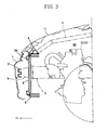
- FIG. 3 is a sectional view taken along the line III-III in FIG. 1
- FIG. 4 is a sectional view taken along the line IV-IV in FIG. 1
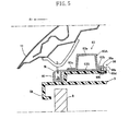
- FIG. 5 is a sectional view showing a joint structure of a shroud panel 5 and a panel support member 6 at the central part in the car width direction of the panel support member 6
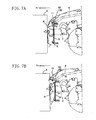
- FIG. 6 is a sectional view showing the joint structure of the shroud panel 5 and the panel support member 6 at the right and left side parts of the panel support member 6.
- the front, the rear, the right, and the left of the automobile are referred to as mere the front, the rear, the right, and the left, respectively.
- the front side of the automobile is denoted by Fr in the drawings.
- the automobile includes at the front end thereof a front bumper 1 extending in the car wise direction. Inside the front bumper 1, a bumper beam 2 extending in the car width direction is provided. This bumper beam 2 is formed by bending a member in a substantially C shape in section opened to the rear so as to be recessed rearward at the central part in the vertical direction thereof for securing the rigidity thereof in the longitudinal direction of the automobile. The bumper beam 2 receives a load at head-on collision (including offset collision) of the automobile.
- right and left front side frames 3, 3 are provided respectively to extend in the longitudinal direction of the automobile.
- the right and left front side frames 3, 3 are arranged along the sides in the longitudinal direction of the automobile in an engine compartment ER , as shown in FIG. 2 , and FIG. 4 , and are in a rectangular shape with a closed section extending in the longitudinal direction of the automobile.
- the side end parts of the bumper beam 2 are fixed to the front end parts of the right and left front side frames 3 , 3 through crush boxes 9, 9 (see FIG. 2 , FIG. 3 , and FIG. 4 ).
- right and left apron rein members 4, 4 are provided respectively to extend in the longitudinal direction of the automobile.
- the right and left apron rein members 4, 4 are provided at the right and left side ends in the upper part of the engine compartment ER, respectively, and are formed in a rectangular shape with a closed section extending in the longitudinal direction of the automobile.
- the apron rein members 4, 4 include front end parts 4a, 4a to which a panel support member 6 is fixed, which will be described later, and the rear end parts (not shown) fixed to the base end (not shown) of the front pillar at the front part of the cabin.
- the panel support member 6 is fixed to the front side frames 3, 3, as will be described later, so that an impact load working on the front side frames 3, 3 works on the apron rein members 4, 4 through the panel support member 6 to be distributed and transmitted to the roof panel (not shown) above the cabin from the apron rein members 4, 4, thereby forming a generally-called upper load path of the impact load.
- the shroud panel 5 is provided which expands in the vertical direction and the car width direction to form a front end wall of the engine compartment ER.
- the panel support member 6 for supporting the shroud panel 5 is provided above the shroud panel 5.
- reference numeral 7 denotes a head lamp
- 12 denotes a power train composed of an engine E and a transmission M.
- the shroud panel 5 is a rectangular frame member composed of an upper part 51 extending in the car width direction, right and left two side parts 52, 52 extending in the vertical direction, and a lower part 53 extending in the car width direction below the upper part 51, as shown in FIG. 1 and FIG. 2 .
- the right and left side parts 52, 52 respectively connect the right and left end parts of the upper part 51 and the lower part 53.
- the shroud panel 5 is made of resin as a whole and is lighter than a metal-made shroud panel.
- the shroud panel 5 supports inside its frame member a radiator R as a heat exchanger and forms a unit in which the radiator R is incorporated in advance, as shown in FIG. 2 .
- Unitization of the shroud panel 5 and the radiator R facilitates the assembly. In detail, only mounting of the shroud panel 5 from above of the automobile (a car body) in the main line of an automobile assembly line results in mounting of the radiator R, thereby facilitating the assembling operation of the vehicle front end part.
- the panel support member 6 includes, as shown in FIG. 2 , right and left side members 61, 61 respectively extending in the longitudinal direction of the automobile behind the right and left head lamps 7, 7, right and left vertical members 62, 62 respectively connecting the right and left side members 61, 61 and the right and left front side frames 3, 3, and a center member 63 extending in the car width direction to connect the right and left side members 61, 61.
- Each side member 61 includes a rear end part 61a welded and fixed to the front end part 4a of the corresponding apron rein member 4 and a front end part 61b located above the front end part of the corresponding front side frame 3.
- Each vertical member 62 has an upper end part welded and fixed to the front end part 61b of the corresponding side member 61 and a lower end part welded and fixed to the front end part of the corresponding front side frame 3.
- a pocket part 60 is formed for accommodating a bonnet locking mechanism BL (see FIG. 5 ) locking the bonnet 11.
- the pocket part 60 is in a substantially rectangular box shape of which upper part is opened.
- Each side member 61 is in a substantially rectangular shape in section. As shown in FIG. 2 , each side member 61 tilts so that the front end part 61b thereof is located slightly more inboard than the rear end part 61a thereof.
- Each vertical member 62 is formed in a substantially rectangular shape in section extending in the vertical direction below the corresponding placement part 64.
- the vertical members 62 connect the corresponding placement parts 64, 64 of the side members 61, 61 and the corresponding front side frames 3, 3. Provision of the vertical members 62, 62 increases the supporting rigidity of the placement parts 64, 64 of the side members 61, 61 .
- Each vertical member 62 also connects the corresponding front side frame 3 and the panel support member 6 to allow an impact load working on the front side frames 3, 3 to be distributed and transmitted to the apron rein members 4, 4 through the panel support member 6.
- the center member 63 linearly extends in the car width direction above the shroud panel 5 and is formed in a closed section by two members 63A, 63B.
- the member 63A has a section along the longitudinal direction of the automobile which includes a main body 63a in a substantially reverse U shape and front and rear flanges 63c, 63b formed at the ends of the main body 63a in the longitudinal direction of the automobile.
- the member 63B is a flat plate member.
- the right and left side end parts of the center member 63 are placed on the placement parts 64, 64 of the right and left side members 61, 61, respectively, and are detachably fastened and fixed to the placement parts 64, 64 by means of fastener 65, 65, such as fastening bolt/nut pairs.
- the center member 63 is fastened and fixed to the upper face of the upper part 51 of the shroud panel 5 at three points thereof, namely, the center thereof in the car width direction and the right and left side ends thereof, so that the panel support member 6 serves as a panel support part of the present invention supporting the shroud panel 5 against the apron rein members 4, 4 as car body members.
- the center member 63 is capable of being provisionally fixed to the upper face of the upper part 51 of the shroud panel 5 before being mounted to the automobile, as shown in FIG. 2 , so as to be mounted in advance to the upper part to the shroud panel 5 as a unit. Mounting in advance of the center member 63 to the shroud panel 5 eliminates the need for separate mounting of the shroud panel 5 and the center member 63 in the main line of the automobile assembly line, thereby simplifying the assembling operation of the vehicle front end part.
- the rear flange 63b of the member 63A of the center member 63 is fastened and fixed to the upper part 51 of the shroud panel 5 by means of a center joint bolt 66a and a center joint nut 66b at the center in the car width direction of the center member 63.
- the center joint bolt 66a extends in the vertical direction while the center joint nut 66b is buried in and fixed to the upper part 51 of the shroud panel 5 to be in screw engagement with the center joint bolt 66a .
- a joint part 66 is formed at the center in the car width direction of the center member 63.
- a center notch 66c is formed which is opened to the rear and through which the center joint bolt 66a is inserted.
- a center notch 66d similar to the center notch 66c is formed at a part of the member 63B correspondingly to the center notch 66c.
- the joint force of the center joint bolt 66a is set so that when an impact load works on the shroud panel 5 from the front, the center joint bolt 66a and the center joint nut 66b move rearward together with the shroud panel 5 relative to the center member 63 to fall off from the center notches 66c, 66d. Namely, the fastening and fixing of the center member 63 at the joint part 66 is released upon head-on collision of the automobile.
- the aforementioned pocket part 60 is integrally formed with the center member 63. This integral formation of the pocket part 60 secures the bonnet locking mechanism BL at the center member 63 even if the shroud panel 5 retreats to release the fastening of the center member 63 to the shroud panel 5 upon head-on collision of the automobile.
- the front flange 63c of the member 63A of the center member 63 is fastened and fixed to the upper part 51 of the shroud upper panel 5 by means of side joint bolts 68a extending in the vertical direction and side joint nuts 68b in screw engagement with the side joint bolts 68a at the right and left end side parts of the center member 63.
- the side joint nuts 68b are generally-called half nuts and maintain their fastening state by being screwed at the rear part thereof by the side joint bolts 68a. Accordingly, the joint parts 68, 68 are formed at the right and left side end parts of the center member 63
- Side notches 51a which are opened to the front and through which the side joint bolts 68a are inserted are formed in joint parts of the upper part 51 of the shroud panel 5 (parts corresponding to the joint parts 68, 68 ) where the side joint bolts 68a and the side joint nuts 68b are in screw engagement with each other.
- the side joint nuts 68b are fixed at the rear end parts of the side notches 51a .
- through holes through which the side joint bolts 68a are inserted are formed in the joint parts of the front flange 63c while notches (or through holes) opened to the front are formed at parts of the member 63B which correspond to the through holes.
- the shroud panel 5 and the radiator R move rearward relative to the center member 63.
- the joint parts 66, 68, 68 serve as a rearward movement allowing part in the present invention.
- a front end part 5A of the shroud panel 5 is located ahead of the center member 63 . Because, a part supporting the radiator R is set ahead of the engine compartment ER so as not to invite interference of the shroud panel 5 with the power train 12. Further, as will be described later, this structure allows the shroud panel 5 to receive an impact load from the front more readily than the center member 63.
- right and left joint brackets 10, 10 extending in the longitudinal direction of the automobile are provided between the side parts 52, 52 of the shroud panel 5 and the bumper beam 2 for more stably supporting the shroud panel 5.
- a front end flange 10a of each joint bracket 10 is fixed to the rear face of the bumper beam 2 while a rear end flange 10b of each joint bracket 10 is fixed to the corresponding side part 52 of the shroud panel 5. Accordingly, the side parts 52, 52 of the shroud panel 5 are fixed to the bumper beam 2 through the joint brackets 10, 10.
- the front bumper 1 (the bumper beam 2 ) receives an impact load from the front
- the impact load is transmitted to the shroud panel 5 through the joint brackets 10, 10.
- the joint brackets 10, 10 secure the space in the longitudinal direction of the automobile between the bumper beam 2 and the shroud panel 5 at head-on collision of the automobile to invite no interference of the bumper beam 2 with the shroud panel 5.
- the shroud panel 5 is supported by the bumper beam 2 even after collision to prevent the shroud panel 5 from wholly falling off from the automobile.
- a colliding object X collides with the front end part of the automobile to make a rearward impact load to work on the front bumper 1 (the bumper beam 2 ).
- the bumper beam 2 is supported by the crush boxes 9, 9, and therefore, the crash boxes 9, 9 are buckled and deformed first at the collision to absorb impact energy. The, the buckling and deformation of each crash box 9 causes the bumper beam 2 to retreat.
- the rearward impact load works also on the shroud panel 5 fastened and fixed by means of the joint brackets 10, 10 (see FIG. 4 ) to cause behavior of rearward movement.
- the arrangement of the shroud panel 5 before the center member 63 causes behavior of the rearward movement of the shroud panel 5 even at light collision. Since the joint structure of the center member 63 to the shroud panel 5 is releasable by rearward movement of the shroud panel 5, the should panel 5 moves rearward relative to the center member 63 with the center member 63 not moved, thereby causing the shroud member 5 to separate from the center member 63.
- the shroud panel 5 (especially, the front end part 5A thereof) is overlapped with the crash boxes 9 when viewed from a side of the automobile. Accordingly, even upon light collision, upon which only the crash boxes 9, 9 are buckled and deformed with the front side frames 3, 3 not buckled and deformed, the impact load causing rearward movement of the shroud panel 5 works definitely to cause the shroud panel 5 to retreat and separate from the center member 63
- the shroud panel 5 retreats and the radiator R retreats together with the shroud panel 5 to invite no interference of the radiator R with the bumper beam 2 to cause no breakage of the radiator R.
- the rearward movement of the shroud panel 5 is caused without inviting brakeage and the like of itself and therefore involves no breakage of itself.
- the panel support member 6 including the center member 63 is no broken at all. Accordingly, light collision necessitates replacement of only a low-cost component, such as the front bumper 1, the bumper beam 2, the shroud panel 5, the crash boxes 9, 9, or the like for repairing the front end part of the automobile.
- the impact load transmitted to the front side frames 3, 3 is also transmitted to the apron rein members 4, 4 through the panel support member 6, thereby attaining appropriate distribution of the impact load to increase the safety performance at collision.
- the joint parts 66, 68, 68 are formed for allowing the shroud panel 5 and the radiator R to move rearward relative to the center member 63 of the panel support member 6 when an impact load works on the shroud panel 5 from the front.
- the joint parts 66, 68, 68 fix the upper part 51 of the shroud panel 5 to the center member 63 and allows, when an impact load works on the shroud panel 5 from the front, the upper part 51 to separate from the center member 63 to allow the shroud panel 5 and the radiator R to move rearward relative to the center member 63.
- Each structure of the joint parts 66, 68, 68 allows the shroud panel 5, which is fixed by means of the center joint bolt 66a, the center joint nut 66b, the side joint bolts 68a, and the side joint nuts 68b, to separate from the center member 63 and retreats rearward upon light collision. Accordingly, interference of the bumper beam 2 with the shroud panel 5 and the radiator R can be prevented even if the front bumper 1 (the bumper beam 2 ) retreats, thereby preventing the radiator R and the shroud panel 5 from being broken.
- the impact load works also on the panel support member 6 to be distributed and transmitted to the apron rein members 4, 4 therebehind through the panel support member 6.
- the impact load distribution performance at heavy collision can be enhanced while the repair cost can be reduced by preventing the radiator R and the shroud panel 5 from being broken at light collision as far as possible.
- the shroud panel 5 in the case where the radiators R supported by the shroud panel 5 have almost the same size, the shroud panel 5 can be used in common to automobiles different in outer contours from each other, which means that only change of the panel support member 6 suffices according to the outer contours.
- the shroud panel 5 supports only the radiator R in the present embodiment, but the present invention is not limited thereto.
- the shroud panel 5 may be one supporting a condenser of an air conditioner, an intercooler of a supercharger for the engine E, or the like (the same is applied to Embodiments 2 to 6 as will be described later).
- the panel support member 6 in the present embodiment includes the side members 61, 61, the vertical members 62, 62, and the center member 63 detachably fastened and fixed to the side members 61, 61.
- the shroud panel 5 can be mounted from above of the automobile with the center member 63 taken off therefrom. Hence, the degree of freedom of the automobile assembling operation can be increased even though the panel support member 6 is arranged above the shroud panel 5.
- the whole panel support member 6 may be fastened and fixed detachably to the front end parts 4a , 4a of the apron rein members 4, 4, rather than detachable fastening of only the center member 63 of the panel support member 6.
- the center member 63 is fixed provisionally on the upper face of the upper part 51 of the shroud panel 5 before being mounted to the automobile.
- the center member 63 can be mounted from above of the automobile (the car body) as a unit together with the shroud panel 5. This eliminates the need for separate mounting for the shroud panel 5 and the center member 63 in the main line of the automobile assembly line, thereby reducing the operation man hour to shorten the time required for assembling.
- the upper part 51 of the shroud panel 5 is fastened and fixed to the flanges 63c, 63b of the member 63A of the center member 63.
- the center notch 66c is formed in the rear flange 63b while the through holes are formed in the front flange 63c. Formation of the center notch 66c and the through holes involves less or no influence of rigidity lowering on the center member 63, thereby involving no lowering of the rigidity of the center member 63.
- the shroud panel 5 can be fastened and fixed to the center member 63 without inviting lowering of the load transmission performance of the center member 63 (the panel support member 6) at heavy collision.
- the center notch 63c opened to the rear and the side notches 51a opened to the front are formed in the rear flange 63b and the upper part 51 of the shroud panel 5, respectively.
- This simple structure facilitates separation of the shroud panel 5 from the center member 63.
- the pocket part 60 is formed in the center member 63 for accommodating the bonnet locking mechanism BL to prevent the bonnet locking mechanism BL from retreating even when the shroud panel 5 separates from the center member 63 and retreats at light collision.
- the radiator R can be prevented from being broken at light collision while the bonnet supporting rigidity of the bonnet locking mechanism BL can be increased.
- fixing flanges 60a, 60a may be provided at lower side parts of the pocket part 60 provided at the center member 63 so that the pocket part 60 is fastened and fixed to the upper part 51 of the shroud panel 5 through the fixed flanges 60a, 60a.
- This structure increases the supporting rigidity of the pocket part 60, and the supporting rigidity of the bonnet locking mechanism BL is increased by using the shroud panel 5. Further, the fastening and fixing of the fixing flanges 60a, 60a to the shroud panel 5 is released upon head-on collision of the automobile to inhibit no retreat of the shroud panel 5. Hence, both enhancement of the supporting rigidity of the bonnet locking mechanism BL and promotion of retreat of the shroud panel 5 at head-on collision can be contemplated.
- the shroud panel 5 is overlapped with the crash boxes 9, 9 when viewed from a side of the automobile.
- FIG. 9 shows Embodiment 2 of the present invention, in which the fixing structure of the center member 63 of the panel support member 6 to the shroud panel 5 is different from that in Embodiment 1.
- the same reference numerals are assigned to the same components as in Embodiment 1 for omitting the description thereof (the same is applied to the following Embodiments 3 to 6).
- a resin-made press-in pin 166 is pressed in the upper part 51 of the shroud panel 5 from above of the rear flange 63b of the member 63A of the center member 63 at the center in the car width direction of the center member 63 to press and fix the rear flange 63b to the upper part 51 of the shroud panel 5.
- a through hole is formed rather than the notch in Embodiment 1, through which the pressing pin 166 is inserted.
- Additional press-in pins 166 press and fix the front flange 63c to the upper part 51 of the shroud panel 5 at the right and left side parts of the center member 63, similarly to that at the center in the car width direction.
- Each press-in pin 166 is made of a resin material more fragile than that of the shroud panel 5 to an extent that the shroud panel 5 is broken upon receipt of a rearward impact load. Accordingly, the pressing and fixing state of the center member 63 to the shroud panel 5 can be released even upon light collision to allow the upper part 51 of the shroud panel 5 to separate from the center member 63.
- the structure according to the present embodiment eliminates the need to form notches in the rear flange 63b and the upper part 51 of the shroud panel 5, thereby simplifying the processing of the center member 63 and the shroud panel 5.
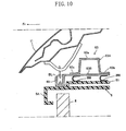
- FIG. 10 shows Embodiment 3 of the present invention, in which the fixing structure of the center member 63 of the panel support member 6 to the shroud panel 5 is different from those in Embodiments 1 and 2.
- a plurality (two in FIG. 10 ) of resin-made to-be-broken members 266, 266 in a substantially U shape in section are interposed between the center member 63 and the upper part 51 of the shroud panel 5 to fix the center member 63 to the upper part 51 of the shroud panel 5.
- the upper faces of the to-be-broken members 266, 266 are fastened and fixed to the rear flange 63b or the front flange 63c with the member 63B interposed while the lower faces thereof are fastened and fixed to the upper part 51 of the shroud panel 5 (by means of bolts or the like not shown in FIG. 10 ).
- Fixing of the upper face and the lower face of each to-be-broken member 266 is not limited to fastening. Further, the number of and arrangement of the to-be-broken members 266 are set appropriately according to the strength of the to-be-broken members 266. For example, as the joint parts 66, 68, 68 in Embodiment 1, three to-be-broken members 266 are provided in total at the center in the car width direction and the right and left side parts of the center member 63.
- the to-be-broken members 266 are made of a resin material more fragile than that of the shroud panel 5 to an extent that the shroud panel 5 is broken upon receipt of the rearward impact road at light collision, similarly to the press-in pins 166 in Embodiment 2. This allows fixing of the center member 63 to the shroud panel 5 to be released upon light collision, thereby separating the upper part 51 of the shroud panel 5 from the center member 63.
- each to-be-broken member 266 is allowed to be broken to prevent definitely the shroud panel 5 from being broken, thereby eliminating the need for replacement of the shroud panel 5.
- the fixing structure of the panel support member 6 to the shroud panel 5 is not limited to the fixing structures described in Embodiments 1 to 3 and may be a fixing structure by an engaging member or a bonding member.
- FIG. 11 to FIG. 17 show Embodiment 4 of the present invention, in which the structure of the shroud panel 5 and the structure of the panel support part supporting the shroud panel 5 are different from those in Embodiments 1 to 3.
- the shroud panel 5 is basically made of a resin material, in a part of which a metal-made rein member 54 (reinforcement) is insert-formed.
- the part where the metal-made rein member 54 is insert-formed serves as a reinforcing part 55 integrally formed with the shroud panel 5 to exhibit almost the same rigidity as that of a metal-made shroud panel.
- the reinforcing part 55 is a substitution of the panel support member 6 in Embodiments 1 to 3, as a panel support part of the present invention.
- the upper part 51 of the shroud panel 5 includes right and left arms 51a, 51a at the right and left sides thereof respectively protruding and extending sideward and rearward and the center upper part 51b between the arms 51a , 51a.
- the reinforcing part 55 includes the arms 51a , 51a, and the center upper part 51b of the upper part 51, the side parts 52, 52, and the lower part 53, wherein the reinforcing parts corresponding to the arms 51a, 51a, the center upper part 51b , the side parts 52, 52, and the lower part 53 are called arm reinforcing parts 55A, 55A, an upper reinforcing part 55B, side reinforcing parts 55C, 55C, and a lower reinforcing part 55D, respectively.
- the upper reinforcing part 55B, the side reinforcing parts 55C, 55C, and the lower reinforcing part 55D form a rectangular flame which is called a frame-like reinforcing part 55E as a unit of these reinforcing parts 55B, 55C, 55C, 55D.
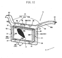
- a radiator support part 56 in a rectangular frame shape which protrudes frontward from the frame-like reinforcing part 55E so that the front end thereof is located ahead of the front end of the frame-like reinforcing part 55E.
- the radiator support part 56 includes an upper frame part 56A extending in the car width direction, right and left side frame parts 56B, 56B extending in the vertical direction, and a lower frame part 56C extending in the car width direction.
- the side frame parts 56B , 56B connect the right side ends and the left side ends of the upper frame part 56A and the lower frame part 56C.
- the radiator support part 56 supports the radiator R through four support members 57 arranged at the right and left side parts of the upper frame part 56A and the lower frame part 56C.
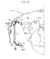
- the radiator support part 56 includes, around the entire periphery thereof, a rise wall 56a protruding frontward from the frame-like reinforcing part 55E and a load receiving part 56b extending inward of the frame from the front end of the rise wall 56a, as shown in FIG. 14 and FIG. 15 .
- the load receiving part 56b receives an impact load from the bumper beam 2.
- a thin to-be-broken part 58 is formed to surround the entire periphery of the radiator support part 56, as shown in FIG. 12 .
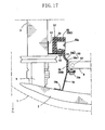
- the thin to-be-broken part 58 is composed of a joint wall part 58a which connects the frame-like reinforcing part 55E and the radiator support part 56 and in which a recess 58b in a V-shape in section is formed, as shown in FIG. 15 and FIG. 17 , and is formed simultaneously with formation of the shroud panel 5.
- the thin to-be-broken part 58 When an impact load larger than a predetermined value works on the radiator support part 56 from the front, the thin to-be-broken part 58 is broken from the recess 58b as a starting point. This breakage allows the radiator support part 56 to move rearward relative to the reinforcing part 55 and to separate from the reinforcing part 55. Namely, the thin to-be-broken part 58 forms a fragile part as the rearward movement allowing part in the present invention, and breakage thereof upon receipt of an impact load working on the radiator support part 56 of the shroud panel 5 from the front allows the radiator R and the radiator support part 56 to move rearward relative to the reinforcing part 55.
- the metal-made rein member 54 inside the reinforcing part 55 is formed in a substantially C shape in section, as shown in FIG. 15 and FIG. 17 , and has rigidity to an extent that it is not readily deformed even when a comparatively large load works thereon.
- a pocket part 59 is formed for accommodating the bonnet locking mechanism BL.
- the bonnet locking mechanism BL accommodated in the pocket part 59 is fixed to the upper reinforcing part 55B of the center upper part 51b, as shown in FIG. 15 , and is fastened and fixed to the metal-made rein member 54 by means of a fixing bolt or the like (not shown).
- the bonnet locking mechanism BL does not separate from the center upper part 51b to keep firmly the front end part 11a of the bonnet 11 at the original position thereof.
- apron fixing parts 80 are formed for fastening and fixing the corresponding arm reinforcing parts 55A, 55A to the corresponding front end parts 4a, 4a of the apron rein members 4, 4.
- the unit of the shroud panel 5 in which the radiator R is incorporated in advance can be fastened and fixed easily to the apron rein members 4, 4 by mounting the unit from above of the automobile.
- the reinforcing part 55 (the arm reinforcing parts 55A, 55A ) of the shroud panel 5 can be fixed to the apron rein members 4, 4 firmly.
- bolt fixing holes 81, 81 are formed for fixing the shroud panel 5 to the front side frames 3, 3.
- the base parts of mounting plates 82, 82 in a substantially L shape in section are bonded to the front side frames 3, 3, while the front end parts of the mounting plates 82, 82 are fastened and fixed to the side reinforcing parts 55C of the side parts 52, 52 by means of mounting bolts 83, 83 inserted in the bolt fixing holes 81, 81.
- Fastening and fixing of the mounting plates 82, 82 to the side reinforcing parts 55C, 55C attain firm fixing of the reinforcing part 55 of the shroud panel 5 to the front side frames 3, 3. This fastening and fixing are carried out after the unit of the shroud panel 5 is mounted.
- load transmitting brackets 70, 70 are provided between the side frame parts 56B, 56B of the radiator support part 56 and the bumper beam 2.
- Each load transmitting bracket 70 includes a front flange 70a bonded and fixed to the rear face of the bumper beam 2 and a rear flange 70b fastened and fixed to the front face, namely, the load receiving face 56b of the corresponding side frame part 56B of the radiator support part 56.
- Provision of the load transmitting brackets 70, 70 between the side frame parts 56B, 56B of the radiator support part 56 and the bumper beam 2 achieves transmission of an impact load working on the bumper beam 2 to the radiator support part 56. After collision, the load transmitting brackets 70, 70 still support the radiator support part 56 having separated from the reinforcing part 55.
- a perimeter frame 8 which extends in the car width direction to connect the right and left front side frames 3, 3.
- the perimeter frame 8 includes vertical members 8A, 8A extending in the vertical direction and fastened and fixed at the upper end parts thereof to the front side frames 3, 3 and a transverse member 8B extending in the car width direction to connect the vertical members 8A, 8A .
- the perimeter frame 8 pivotally supports at the vertical members 8A, 8A a suspension arm of a front suspension device (not shown) to function as a suspension cross member supporting the suspension device.
- each joint plate 85 bonded to the lower face of the lower reinforcing part 55D of the lower part 53 and the transverse member 8B of the perimeter frame 8 are fastened and fixed to each other by means of a fastener 86, such as a bolt/nut pair.
- a fastener 86 such as a bolt/nut pair.
- Behavior of rearward movement is caused in the radiator support part 56 to which the impact load is transmitted.
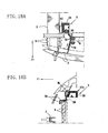
- the behavior of rearward movement bends and breaks the thin to-be-broken part 58 over the entire periphery thereof, as shown in FIG. 18A and FIG. 8 B.
- the reinforcing part 55 which is fixed to the front side frames 3, 3 through the mounting plates 82, 82, will not retreat by the impact load if it is light enough to an extent that the front side frames 3, 3 are not buckled and deformed (light collision). Accordingly, the radiator support part 56 and the radiator R shift rearward relative to the reinforcing part 55 without being restricted by the strong reinforcing part 55, thereby definitely causing breakage of the thin to-be-broken part 58.
- the bonnet locking mechanism BL which is fixed to the upper reinforcing part 55B of the center upper part 51b, will never retreat as well even when the radiator support part 56 separates from the reinforcing part 55 upon head-on collision of the automobile.
- the crash boxes 9, 9 are buckled and deformed to cause the bumper beam 2 to retreat. Accordingly, the radiator support part 56 receives the impact load to shift rearward relative to the reinforcing part 55, with a result that the radiator support part 56 and the radiator R move rearward. Hence, interference of the bumper beam 2 with the radiator R can be prevented even when the bumper beam 2 retreats, thereby preventing the radiator R from being broken at light collision. As shown in FIG. 20A , the radiator support part 56 and the radiator R retreat inside the frame of the reinforcing part 55 of the shroud panel 5, thereby definitely preventing interference with the bumper beam 2.
- the bumper beam 2 further retreats to cause the impact load to be transmitted to the front side frames 3, 3.
- the impact load transmitted to the front side frames 3, 3 works on the reinforcing part 55 of the shroud panel 5 through the mounting plates 82, 82. Since the reinforcing part 55 is fastened and fixed to the apron rein members 4, 4, the impact load transmitted to the front side frames 3, 3 is transmitted to the apron rein members 4, 4 through the reinforcing part 55.
- the impact load can be distributed through the aforementioned under and upper load paths, thereby increasing the safety performance at collision of the automobile by utilizing the reinforcing part 55 of the shroud panel 5.
- the lower reinforcing part 55D of the lower part 53 of the shroud panel 5 is fixed to the perimeter frame 8, so that the impact load can be transmitted to the perimeter frame 8 through the joint plates 85, 85. Hence, the impact load distribution performance can be further enhanced.
- the panel support part is composed of the reinforcing part 55 integrally formed with the shroud panel 5 and including the metal-made reinforcement 54, and the shroud panel 5 includes the radiator support part 56 including the front end part located ahead of the reinforcing part 55 (the frame-like reinforcing part 55E ) and supporting the radiator R and the thin to-be-broken part 58 formed at the boundary part between the reinforcing part 55 and the radiator support part 56.
- This arrangement allows the bumper beam 2 to retreat upon head-on collision of the automobile so that the radiator support part 56 receives the impact load of the collision to retreat.
- the thin to-be-broken part 58 is broken to shift the radiator support part 56 relative to the reinforcing part 55, thereby causing the radiator R to retreat.
- interference of the bumper beam 2 with the radiator R can be prevented.
- the radiator R supported by the shroud panel 5 can be prevented from being broken.
- the impact load transmitted to the front side frames 3, 3 is distributed ant transmitted to the apron rein members 4, 4 and the perimeter frame 8 through the reinforcing part 55.
- the load distribution performance of the shroud panel 5 to the car body members at heavy collision can be enhanced while the repair cost can be reduced by preventing the radiator R from being broken as far as possible at light collision.
- the thin to-be-broken part 58 is formed simultaneously with formation of the shroud panel 5, which means easy formation of the thin to-be-broken part 58 and invites no lowering of the productivity of the shroud panel 5.
- a slip part 158 shown in FIG. 21 may be formed as a fragile part at the boundary part between the reinforcing part 55 and the radiator support part 56. Formation of the slit part 158 promotes breakage of the boundary part upon reception of an impact load, thereby contemplating both protection of the radiator R at light collision and enhancement of the load distribution performance at heavy collision.
- the slit part 158 can be formed simultaneously with formation of the shroud panel 5, likewise formation of the thin to-be-broken part 58, and therefore, no lowering of the productivity of the shroud panel 5 is involved.
- the upper part 51, the side parts 52, 52, and the lower part 53 of the shroud panel 5 form the reinforcing part 55, that is, the frame-like reinforcing part 55E to surround the radiator R, the arm reinforcing parts 55A, 55A are fixed to the apron rein members 4, 4, and the side reinforcing parts 55C, 55C of the side parts 52, 52 are fixed to the front side frames 3, 3.
- the lower reinforcing part 55D of the lower part 53 of the shroud panel 5 is fixed to the perimeter frame 8.
- This arrangement secures fixing of the lower part 53 to cause relative shift of the radiator support part 56 definitely at light collision, thereby allowing the radiator R and the radiator support part 56 to retreat.
- the impact load can be transmitted to the perimeter frame 8 through the lower part 53.
- utilization of the perimeter frame 8 enhances both the protection performance for the radiator R at light collision and the load distribution performance at heavy collision.
- the joint plates 70 are provided between the radiator support part 56 and the bumper beam 2 in the present embodiment, so that the radiator support part 56 retreats together with the bumper beam 2 upon head-on collision of the automobile. This involves no interference of the radiator R supported by the radiator support part 56 with the bumper beam 2 to prevent definitely the radiator R from being broken. Definite prevention of the radiator R from being broken leads to contemplation of reduction in repair cost.
- the bonnet locking mechanism BL for locking the bonnet 11 is arranged at the upper reinforcing part 55B to be prevented from retreating even when the radiator support part 56 is broken and separates from the reinforcing part 55 at light collision.
- the bonnet locking mechanism BL increases the supporting rigidity of the bonnet 11 at collision.
- the reinforcing part 55 is fixed to the car body members, namely, the front side frames 3, 3, the apron rein members 4, 4, and the perimeter frame 8 behind the crash boxes 9, 9, firm fixing of the reinforcing part 55 to the car body members is maintained with no influence of buckling and deformation of the crash boxes 9, 9 at light collision received.
- the reinforcing part 55 will not shift at light collision to cause relative shift between the reinforcing part 55 and the radiator support part 56, thereby definitely causing breakage of the thin to-be-broken part 58.
- the impact load is transmitted to the car body members appropriately to thus enhance the load distribution performance.
- the other car body members may be car body panels, such as a wheel house apron and the like in addition to the apron rein members 4, 4 and the perimeter frame 8.
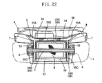
- FIG. 22 shows Embodiment 5 of the present invention, in which the structure of the reinforcing part 55 of the shroud panel 5 is different from that in Embodiment 4.
- the lower reinforcing part 55D is not formed at the lower part 53 so that the reinforcing part 55 is composed of the arm reinforcing parts 55A, 55A and the upper reinforcing part 55B of the upper part 51 and the side reinforcing parts 55C, 55C of the side parts 52, 52.
- the thin to-be-broken part 58 formed at the boundary part between the reinforcing part 55 of the shroud panel 5 and the radiator support part 56 is not formed annularly but is composed of an upper part 58A formed at the boundary part between the upper reinforcing part 55B and an upper frame part 56A of the radiator support part 56 and right and left two side parts 58B, 58B formed at the boundary part between the side reinforcing parts 55C, 55C and the side frame parts 56B, 56B.
- the side parts 58B, 58B extend in the vertical direction from the right and left side ends of the upper part 58A to the lower end of the shroud panel 5.
- the reinforcing part 55 is fastened and fixed to the front side frames 3, 3 and the apron rein members 4, 4.
- the same impact load distribution performance at heavy collision as in Embodiment 4 can be obtained.
- the lower part 53 is not fixed to the perimeter frame 8 in the present embodiment but may be fixed to the perimeter frame 8.
- the thin to-be-broken part 58 is broken to cause rearward movement of the radiator support part 56 and the radiator R, thereby preventing the radiator R from being broken at light collision.
- the amount of the metal-made rein member 54 can be reduced, leading to reduction in weight of the shroud panel 5 when compared with that in Embodiment 4. Further, insert molding of the rein member 54 is facilitated.
- the weight of the front end part of the automobile can be reduced to enhance the safety in automobile maneuver.
- the load transmission performance of the shroud panel 5 at heavy collision can be enhanced without inviting lowering of the formability of the shroud panel 5.
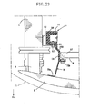
- FIG. 23 shows Embodiment 6 of the present invention, in which the boundary part between the reinforcing part 55 of the shroud panel 5 and the radiator support part 56 is different in structure from those in Embodiment 4 and 5.
- the boundary part is composed of a rubber member 258 as a fragile part.
- the rubber member 258 is interposed between the reinforcing part 55 and the radiator support part 56 by adhesion and fixing of the resin-made reinforcing part 55 to the radiator support part 56.
- the reinforcing part 55 includes, similarly to that in Embodiment 4, the frame-like reinforcing part 55E and is fastened and fixed to the front side frames 3, 3, the apron rein members 4, 4, and the perimeter frame 8.
- the rubber member 258 is formed annularly.
- the rubber member 258 is elastically deformed upon light collision to cause the radiator support part 56 and the radiator R to shift relative to the reinforcing part 55, thereby preventing interference of the bumper beam 2 with the radiator R.
- the rubber member 258 can be formed at the boundary part between the reinforcing part 55 and the radiator support part 56.
- the present invention is not limited to the above embodiments and applicable to front end structures of various kinds of automobiles.
Claims (15)
- Structure frontale pour une automobile comprenant :un panneau de collecteur d'air fabriqué en résine (5) pour supporter un échangeur thermique (R) qui inclut : une partie supérieure (51) s'étendant dans un sens de la largeur de la voiture ; une partie inférieure (53) s'étendant dans le sens de la largeur de la voiture ; et deux parties latérales (52) s'étendant dans une direction verticale pour connecter la partie supérieure et la partie inférieure ;un pare-chocs avant (1) incluant une poutre de pare-chocs (2) s'étendant dans le sens de la largeur de la voiture sur un côté avant de l'automobile du panneau de collecteur d' air ;une partie de support de panneau (6, 55) supportant le panneau de collecteur d'air contre des éléments de carrosserie de voiture (3, 4, 8) ; etune partie permettant un mouvement vers l'arrière (66, 68, 166, 266, 58, 158, 258) qui permet à l'échangeur thermique de se déplacer vers l'arrière de l'automobile par rapport à la partie de support de panneau lorsqu'une charge d'impact agit sur le panneau de collecteur d'air depuis l'avant de l'automobile, caractérisée en ce quela partie de support de panneau (6) s'étend dans le sens de la largeur de la voiture au-dessus du panneau de collecteur d'air, etla partie permettant un mouvement vers l'arrière (66, 68, 166, 266) fixe la partie supérieure du panneau de collecteur d'air à la partie de support de panneau et permet, lorsque la charge d'impact agit sur le panneau de collecteur d'air depuis l'avant de l'automobile, à la partie supérieure de se séparer de la partie de support de panneau.
- Structure frontale selon la revendication 1, dans laquelle la partie de support de panneau inclut :des éléments latéraux droit et gauche (61) incluant respectivement des parties d'extrémité arrière (61a) fixées à des parties d'extrémité avant (4a) des éléments de rêne de traverse droit et gauche respectifs (4) en tant que deux des éléments de carrosserie de voiture et des parties d'extrémité avant (61b) situées au-dessus de parties d'extrémité avant des châssis latéraux avant droit et gauche respectifs (3) en tant que deux des éléments de carrosserie de voiture ;des éléments verticaux droit et gauche (62) incluant respectivement des parties d'extrémité supérieure fixées aux parties d'extrémité avant des éléments latéraux droit et gauche respectifs et des parties d'extrémité inférieure fixées aux parties d'extrémité avant des châssis latéraux avant droit et gauche respectifs ; etun élément central (63) s'étendant dans le sens de la largeur de la voiture pour connecter les éléments latéraux droit et gauche, l'élément central étant relié et fixé de manière amovible aux éléments latéraux droit et gauche.
- Structure frontale selon la revendication 2, dans laquelle l'élément central est capable d'être fixé de manière provisoire à une face supérieure de la partie supérieure du panneau de collecteur d'air avant d'être monté sur l'automobile.
- Structure frontale selon l'une quelconque des revendications 1 à 3, dans laquelle les parties latérales du panneau de collecteur d'air sont fixées à la poutre de pare-chocs.
- Structure frontale selon l'une quelconque des revendications 1 à 4, dans laquelle la partie de support de panneau inclut un corps principal (63a) sous une forme essentiellement en U inversé en coupe le long d'une direction longitudinale de l'automobile et des brides avant et arrière (63c, 63b) formées sur des côtés dans la direction longitudinale de l'automobile du corps principal, et
la partie permettant un mouvement vers l'arrière inclut un élément de joint (66a, 66b, 68a, 68b) pour relier et fixer la partie supérieure du panneau de collecteur d'air à au moins une des brides. - Structure frontale selon la revendication 5, dans laquelle l'élément de joint (66a, 66b) relie et fixe la partie supérieure du panneau de collecteur d'air à la bride arrière (63b),
une encoche (66c) qui est ouverte vers l'arrière de l'automobile et à travers laquelle l'élément de joint est inséré est formée au niveau d'une partie de joint par l'élément de joint dans la bride arrière, et
la partie permettant un mouvement vers l'arrière permet à la partie supérieure du panneau de collecteur d'air de se séparer de la partie de support de panneau en séparant l'élément de joint de l'encoche lorsque la charge d'impact agit sur le panneau de collecteur d'air depuis l'avant de l'automobile. - Structure frontale selon la revendication 5, dans laquelle l'élément de joint (68a, 68b) relie et fixe la partie supérieure du panneau de collecteur d'air à la bride avant (63c),
une encoche (51a) qui est ouverte vers l'avant de l'automobile et à travers laquelle l'élément de joint est inséré est formée au niveau d'une partie de joint par l'élément de joint dans la partie supérieure du panneau de collecteur d'air, et la partie permettant un mouvement vers l'arrière permet à la partie supérieure du panneau de collecteur d'air de se séparer de la partie de support de panneau en séparant l'élément de joint de l'encoche lorsque la charge d'impact agit sur le panneau de collecteur d'air depuis l'avant de l'automobile. - Structure frontale selon l'une quelconque des revendications 1 à 7,
une partie de poche (60) pour recevoir un mécanisme de verrouillage de capot (BL) verrouillant un capot (11) de l'automobile est prévue dans la partie de support de panneau,
dans laquelle une bride de fixation (60a) est de préférence formée dans une partie inférieure de la partie de poche, la bride de fixation étant fixée à la partie supérieure du panneau de collecteur d'air et capable d'être libérée de la fixation lorsque la charge d'impact agit sur le panneau de collecteur d'air depuis l'avant de l'automobile. - Structure frontale selon l'une quelconque des revendications 1 à 8, dans laquelle des boîtes-tampon (9) sont prévues aux extrémités avant des châssis latéraux avant droit et gauche (3) de l'automobile,
la poutre de pare-chocs (2) est montée sur les châssis latéraux avant droit et gauche à travers les boîtes-tampon (9), et
le panneau de collecteur d'air (5) est chevauché par les boîtes-tampon (9) lorsqu'il est visualisé d'un côté de l'automobile. - Structure frontale selon l'une des revendications précédentes, dans laquelle la partie de support de panneau (55) est composée d'une partie de renforcement (55) intégralement formée du panneau de collecteur d'air et incluant un renforcement fabriqué en métal (54), et le panneau de collecteur d'air inclut :une partie de support d'échangeur thermique (56) incluant une extrémité avant située devant la partie de renforcement et supportant l'échangeur thermique ; etune partie fragile (58, 158, 258) en tant que partie permettant un mouvement vers l'arrière qui est formée au niveau d'une partie limite entre la partie de renforcement et la partie de support d'échangeur thermique, la partie fragile permettant à la partie de support d'échangeur thermique et l'échangeur thermique de se déplacer vers l'arrière de l'automobile par rapport à la partie de renforcement lorsque la charge d'impact agit sur la partie de support d'échangeur thermique du panneau de collecteur d'air depuis l'avant de l'automobile.
- Structure avant selon la revendication 10, dans laquelle
la partie fragile forme une fine partie (58) ou une partie fendue (158) au niveau de la partie limite entre la partie de renforcement et la partie de support d'échangeur thermique ou la partie fragile est composée d'un élément de caoutchouc (258) au niveau de la partie limite entre la partie de renforcement et la partie de support d'échangeur thermique. - Structure frontale selon la revendication 10 ou 11, dans laquelle la partie de renforcement est formée en continu de la partie supérieure aux parties latérales du panneau de collecteur d'air,
les parties latérales droite et gauche de la partie de renforcement (55A) au niveau de la partie supérieure sont fixées à des éléments de rêne de traverse droit et gauche (4) en tant que deux des éléments de carrosserie de voiture, respectivement, et
l'élément de renforcement (55C) au niveau des parties latérales est fixé à des châssis latéraux avant droit et gauche correspondants (3) en tant que deux des éléments de carrosserie de voiture. - Structure frontale selon la revendication 12, dans laquelle la partie de renforcement est formée sous une forme de type cadre au niveau de la partie supérieure, de la partie inférieure et des parties latérales,
dans laquelle la partie de renforcement (55D) au niveau de la partie inférieure est de préférence fixée à une traverse de suspension en tant qu'un des éléments de carrosserie de voiture (8) supportant un dispositif de suspension. - Structure frontale selon la revendication 12 ou 13, dans laquelle un mécanisme de verrouillage de capot (BL) pour verrouiller un capot (11) de l'automobile est prévu au niveau de la partie de renforcement (55B) au niveau de la partie supérieure.
- Structure frontale selon l'une quelconque des revendications 10 à 14, dans laquelle
la partie de support d'échangeur thermique inclut une partie de cadre supérieure (56A) s'étendant dans le sens de la largeur de la voiture, une partie de cadre inférieure (56C) s'étendant dans le sens de la largeur de la voiture et des parties de cadre latérales (56B) s'étendant dans une direction verticale pour connecter la partie de cadre supérieure et la partie de cadre inférieure, les parties de cadre latérales étant fixées à la poutre de pare-chocs, et/ou
dans laquelle
des boîtes-tampon sont prévues au niveau de parties d'extrémité avant de châssis latéraux avant droit et gauche (3) de l'automobile,
la poutre de pare-chocs est montée sur les châssis latéraux avant droit et gauche à travers les boîtes-tampon, et
la partie de renforcement est fixée à des éléments (3, 4, 8) en tant que deux des éléments de carrosserie de voiture qui sont situés sur un côté arrière de l'automobile des boîtes-tampon.
Applications Claiming Priority (2)
| Application Number | Priority Date | Filing Date | Title |
|---|---|---|---|
| JP2007257099A JP5167749B2 (ja) | 2007-10-01 | 2007-10-01 | 自動車の前部構造 |
| JP2007257098A JP5176460B2 (ja) | 2007-10-01 | 2007-10-01 | 自動車の前部構造 |
Publications (3)
| Publication Number | Publication Date |
|---|---|
| EP2045170A2 EP2045170A2 (fr) | 2009-04-08 |
| EP2045170A3 EP2045170A3 (fr) | 2009-04-29 |
| EP2045170B1 true EP2045170B1 (fr) | 2013-05-22 |
Family
ID=40091973
Family Applications (1)
| Application Number | Title | Priority Date | Filing Date |
|---|---|---|---|
| EP08017300.8A Expired - Fee Related EP2045170B1 (fr) | 2007-10-01 | 2008-10-01 | Structure avant pour automobile |
Country Status (2)
| Country | Link |
|---|---|
| US (1) | US8220576B2 (fr) |
| EP (1) | EP2045170B1 (fr) |
Families Citing this family (27)
| Publication number | Priority date | Publication date | Assignee | Title |
|---|---|---|---|---|
| JP4506577B2 (ja) * | 2004-09-21 | 2010-07-21 | トヨタ自動車株式会社 | 車両前部構造 |
| DE102005002068A1 (de) * | 2005-01-14 | 2006-08-03 | Behr Gmbh & Co. Kg | Befestigungseinrichtung für eine Wärmetauschereinheit und Fahrzeug mit einer Wärmetauschereinheit |
| DE102006016159A1 (de) * | 2006-04-06 | 2007-11-15 | GM Global Technology Operations, Inc., Detroit | Frontpartie für ein Kraftfahrzeug |
| DE102007020914A1 (de) * | 2007-05-04 | 2008-11-06 | GM Global Technology Operations, Inc., Detroit | Frontaufbau für ein Kraftfahrzeug |
| KR100925926B1 (ko) * | 2008-05-29 | 2009-11-09 | 현대자동차주식회사 | 자동차 프론트엔드부의 듀얼 에어덕트 |
| IT1398269B1 (it) * | 2009-03-26 | 2013-02-22 | Red Stamp Sas | Struttura paraurti |
| DE102009031746A1 (de) * | 2009-07-06 | 2011-01-13 | GM Global Technology Operations, Inc., Detroit | Kühlluftführungseinrichtung für ein Kraftfahrzeug |
| DE102009056508A1 (de) * | 2009-12-02 | 2011-06-09 | Behr Gmbh & Co. Kg | Kühlmodul und Adapterpaar für Modulvereinheitlichung |
| DE102009056443A1 (de) * | 2009-12-02 | 2011-06-09 | Benteler Automobiltechnik Gmbh | Crashbox und Verfahren zu deren Herstellung |
| DE102010011237A1 (de) * | 2010-03-12 | 2011-09-15 | GM Global Technology Operations LLC , (n. d. Ges. d. Staates Delaware) | Karosserierohbau für einen Kraftfahrzeug-Vorderbau und Verfahren zur Herstellung desselben |
| US8152224B2 (en) | 2010-04-21 | 2012-04-10 | Ford Global Technologies | Vehicle front-end upper load path assembly |
| US8419116B2 (en) * | 2010-07-08 | 2013-04-16 | Honda Motor Co., Ltd. | Vehicle frame assembly |
| DE102010043035A1 (de) * | 2010-10-28 | 2012-05-03 | Ford-Werke Gmbh | Frontmodul für ein Kraftfahrzeug |
| CN103391874B (zh) * | 2011-02-23 | 2016-01-06 | 本田技研工业株式会社 | 汽车的车身前部构造 |
| JP5749959B2 (ja) * | 2011-03-30 | 2015-07-15 | 富士重工業株式会社 | 車体前部構造 |
| EP2511119B1 (fr) * | 2011-04-12 | 2014-03-05 | Fiat Group Automobiles S.p.A. | Face avant pour véhicule automobile |
| US20130081888A1 (en) * | 2011-09-30 | 2013-04-04 | GM Global Technology Operations LLC | Reconfigurable baseline opening for under-hood airflow |
| US20140062129A1 (en) * | 2012-09-04 | 2014-03-06 | GM Global Technology Operations LLC | Impact deflection and absorption structure |
| US8931824B2 (en) * | 2013-03-11 | 2015-01-13 | Ford Global Technologies, Llc | Pedestrian-friendly structure for motor vehicle front end |
| JP5969417B2 (ja) * | 2013-03-25 | 2016-08-17 | 富士重工業株式会社 | 車体前部構造 |
| FR3034378A1 (fr) * | 2015-04-01 | 2016-10-07 | Peugeot Citroen Automobiles Sa | Piece de fixation protectrice d’un condenseur d’un groupe moto-ventilateur |
| DE102016112939B4 (de) * | 2016-07-14 | 2023-09-21 | Dr. Ing. H.C. F. Porsche Aktiengesellschaft | Buganordnung für ein Kraftfahrzeug |
| US10131305B2 (en) * | 2017-02-09 | 2018-11-20 | Toyota Motor Engineering & Manufacturing North America, Inc. | Bumper assemblies and vehicles with integrated air deflectors |
| US10131304B2 (en) * | 2017-02-09 | 2018-11-20 | Toyota Motor Engineering & Manufacturing North America, Inc. | Bumper assemblies and vehicles with integrated air deflectors |
| US10131303B2 (en) * | 2017-02-09 | 2018-11-20 | Toyota Motor Engineering & Manufacturing North America, Inc. | Bumper assemblies and vehicles with integrated air deflectors |
| US10479406B2 (en) * | 2017-06-19 | 2019-11-19 | Ford Global Technologies, Llc | Motor vehicle assembly incorporating a front end module, a front suspension and a SORB structure |
| CN112572613B (zh) * | 2019-09-30 | 2022-07-15 | 比亚迪股份有限公司 | 车辆前端模块总成和车辆 |
Family Cites Families (22)
| Publication number | Priority date | Publication date | Assignee | Title |
|---|---|---|---|---|
| JPH10264855A (ja) | 1997-03-26 | 1998-10-06 | Aisin Seiki Co Ltd | 車両フロントエンドモジュール構造 |
| JP2000177633A (ja) | 1998-12-21 | 2000-06-27 | Aisin Seiki Co Ltd | 車両フロントエンドモジュール構造 |
| JP4461563B2 (ja) * | 1999-10-20 | 2010-05-12 | 株式会社デンソー | 車両のフロントエンド構造 |
| JP3526424B2 (ja) * | 1999-11-30 | 2004-05-17 | 本田技研工業株式会社 | ラジエータ取付構造 |
| JP2002155981A (ja) * | 2000-11-21 | 2002-05-31 | Aisin Seiki Co Ltd | 衝撃吸収部材及びバンパ |
| JP3979016B2 (ja) | 2001-02-19 | 2007-09-19 | マツダ株式会社 | 自動車の車体前部構造 |
| US6814381B1 (en) * | 2001-02-21 | 2004-11-09 | Alcan Technology & Management Ltd. | Vehicle with bumper and deformation element |
| WO2003024747A1 (fr) * | 2001-09-14 | 2003-03-27 | Honda Giken Kogyo Kabushiki Kaisha | Structure de grille avant a absorption de choc pour vehicule |
| DE10207025A1 (de) * | 2002-02-20 | 2003-08-28 | Behr Gmbh & Co | Montageträger eines Frontends eines Kraftfahrzeugs und Verfahren zum lösbaren Befestigen eines Kühlmoduls an einem Montageträger eines Frontends |
| JP2004098814A (ja) * | 2002-09-09 | 2004-04-02 | Fuji Heavy Ind Ltd | 車両の熱交換器取付構造 |
| JP2004217028A (ja) | 2003-01-14 | 2004-08-05 | Calsonic Kansei Corp | 車両用ランプの支持構造 |
| JP2004217119A (ja) | 2003-01-16 | 2004-08-05 | Denso Corp | 車両の前端構造及びラジエータサポート |
| JP2005035407A (ja) | 2003-07-15 | 2005-02-10 | Calsonic Kansei Corp | 熱交換器の取付構造 |
| JP2005219531A (ja) | 2004-02-03 | 2005-08-18 | Denso Corp | 車両用熱交換器冷却装置 |
| JP2005219590A (ja) | 2004-02-05 | 2005-08-18 | Nissan Motor Co Ltd | フロントエンドモジュールの車体前部への取り付け構造 |
| JP2006273050A (ja) * | 2005-03-28 | 2006-10-12 | Calsonic Kansei Corp | ラジエータコアサポート構造 |
| JP4853627B2 (ja) | 2005-05-23 | 2012-01-11 | マツダ株式会社 | 自動車のシュラウド支持構造 |
| JP4710519B2 (ja) | 2005-09-28 | 2011-06-29 | マツダ株式会社 | 車体前部構造 |
| US7419208B2 (en) * | 2006-02-03 | 2008-09-02 | Halla Climate Control Corp. | Carrier for front end module of vehicle |
| FR2901231B1 (fr) | 2006-05-22 | 2009-03-27 | Faurecia Bloc Avant | Face avant de vehicule automobile escamotable en choc, et vehicule automobile correspondant |
| US7766112B2 (en) * | 2007-06-18 | 2010-08-03 | Magna International Inc. | Front end module with breakaway radiator |
| FR2919567A1 (fr) | 2007-08-03 | 2009-02-06 | Faurecia Bloc Avant | Face avant de vehicule automobile |
-
2008
- 2008-09-10 US US12/207,568 patent/US8220576B2/en not_active Expired - Fee Related
- 2008-10-01 EP EP08017300.8A patent/EP2045170B1/fr not_active Expired - Fee Related
Also Published As
| Publication number | Publication date |
|---|---|
| US8220576B2 (en) | 2012-07-17 |
| EP2045170A2 (fr) | 2009-04-08 |
| EP2045170A3 (fr) | 2009-04-29 |
| US20090085373A1 (en) | 2009-04-02 |
Similar Documents
| Publication | Publication Date | Title |
|---|---|---|
| EP2045170B1 (fr) | Structure avant pour automobile | |
| CN108657277B (zh) | 前副车架结构 | |
| JP5176460B2 (ja) | 自動車の前部構造 | |
| EP1749731B1 (fr) | Structure arrière de véhicule automobile, et une méthode de montage | |
| EP3556591B1 (fr) | Structure avant de carrosserie de véhicule pour véhicule électrique | |
| EP1902928B1 (fr) | Structure frontale d'un véhicule automobile | |
| US10086881B2 (en) | Front vehicle body structure | |
| JP4092711B1 (ja) | キャブオーバー型車両の前部構造 | |
| JP2009078689A (ja) | ランプ取付け構造 | |
| JP2008037135A (ja) | 車体後部のバッテリ搭載構造 | |
| CN112441125B (zh) | 车身前部结构 | |
| US11077880B2 (en) | Front vehicle body structure of vehicle | |
| CN111284565A (zh) | 车辆的前车身结构 | |
| JP2010000866A (ja) | 車両の前部車体構造 | |
| US20090102236A1 (en) | Front-End Vehicle Structure for a Commercial Vehicle | |
| JP2002255059A (ja) | 自動車の前部車体構造 | |
| JP5167749B2 (ja) | 自動車の前部構造 | |
| CN114644055A (zh) | 用于车辆的前围板结构 | |
| KR20060109632A (ko) | 자동차의 카울사이드패널 보강구조 | |
| JP2005178705A (ja) | 自動車の前部車体構造 | |
| EP2428432B1 (fr) | Châssis antérieur d'un véhicule | |
| CN219634967U (zh) | 用于至少部分电驱动的机动车辆的车辆子结构 | |
| US11814100B2 (en) | Vehicle cradle assembly with impact detachment script | |
| WO2018155152A1 (fr) | Structure de disposition d'accessoire pour véhicule | |
| KR100513463B1 (ko) | 캡마운팅 타입 엔진 마운팅 브라켓트 구조 |
Legal Events
| Date | Code | Title | Description |
|---|---|---|---|
| PUAI | Public reference made under article 153(3) epc to a published international application that has entered the european phase |
Free format text: ORIGINAL CODE: 0009012 |
|
| PUAL | Search report despatched |
Free format text: ORIGINAL CODE: 0009013 |
|
| AK | Designated contracting states |
Kind code of ref document: A2 Designated state(s): AT BE BG CH CY CZ DE DK EE ES FI FR GB GR HR HU IE IS IT LI LT LU LV MC MT NL NO PL PT RO SE SI SK TR |
|
| AX | Request for extension of the european patent |
Extension state: AL BA MK RS |
|
| AK | Designated contracting states |
Kind code of ref document: A3 Designated state(s): AT BE BG CH CY CZ DE DK EE ES FI FR GB GR HR HU IE IS IT LI LT LU LV MC MT NL NO PL PT RO SE SI SK TR |
|
| AX | Request for extension of the european patent |
Extension state: AL BA MK RS |
|
| 17P | Request for examination filed |
Effective date: 20090806 |
|
| 17Q | First examination report despatched |
Effective date: 20090908 |
|
| AKX | Designation fees paid |
Designated state(s): DE |
|
| GRAP | Despatch of communication of intention to grant a patent |
Free format text: ORIGINAL CODE: EPIDOSNIGR1 |
|
| GRAS | Grant fee paid |
Free format text: ORIGINAL CODE: EPIDOSNIGR3 |
|
| GRAA | (expected) grant |
Free format text: ORIGINAL CODE: 0009210 |
|
| AK | Designated contracting states |
Kind code of ref document: B1 Designated state(s): DE |
|
| REG | Reference to a national code |
Ref country code: DE Ref legal event code: R084 Ref document number: 602008024691 Country of ref document: DE |
|
| REG | Reference to a national code |
Ref country code: DE Ref legal event code: R096 Ref document number: 602008024691 Country of ref document: DE Effective date: 20130718 |
|
| REG | Reference to a national code |
Ref country code: DE Ref legal event code: R084 Ref document number: 602008024691 Country of ref document: DE Effective date: 20130621 |
|
| PLBE | No opposition filed within time limit |
Free format text: ORIGINAL CODE: 0009261 |
|
| STAA | Information on the status of an ep patent application or granted ep patent |
Free format text: STATUS: NO OPPOSITION FILED WITHIN TIME LIMIT |
|
| 26N | No opposition filed |
Effective date: 20140225 |
|
| REG | Reference to a national code |
Ref country code: DE Ref legal event code: R097 Ref document number: 602008024691 Country of ref document: DE Effective date: 20140225 |
|
| PGFP | Annual fee paid to national office [announced via postgrant information from national office to epo] |
Ref country code: DE Payment date: 20180918 Year of fee payment: 11 |
|
| REG | Reference to a national code |
Ref country code: DE Ref legal event code: R119 Ref document number: 602008024691 Country of ref document: DE |
|
| PG25 | Lapsed in a contracting state [announced via postgrant information from national office to epo] |
Ref country code: DE Free format text: LAPSE BECAUSE OF NON-PAYMENT OF DUE FEES Effective date: 20200501 |