WO2018155152A1 - Structure de disposition d'accessoire pour véhicule - Google Patents
Structure de disposition d'accessoire pour véhicule Download PDFInfo
- Publication number
- WO2018155152A1 WO2018155152A1 PCT/JP2018/003889 JP2018003889W WO2018155152A1 WO 2018155152 A1 WO2018155152 A1 WO 2018155152A1 JP 2018003889 W JP2018003889 W JP 2018003889W WO 2018155152 A1 WO2018155152 A1 WO 2018155152A1
- Authority
- WO
- WIPO (PCT)
- Prior art keywords
- vehicle
- bracket
- auxiliary machine
- harness
- vertical wall
- Prior art date
Links
Images


Classifications
-
- B—PERFORMING OPERATIONS; TRANSPORTING
- B60—VEHICLES IN GENERAL
- B60R—VEHICLES, VEHICLE FITTINGS, OR VEHICLE PARTS, NOT OTHERWISE PROVIDED FOR
- B60R16/00—Electric or fluid circuits specially adapted for vehicles and not otherwise provided for; Arrangement of elements of electric or fluid circuits specially adapted for vehicles and not otherwise provided for
- B60R16/02—Electric or fluid circuits specially adapted for vehicles and not otherwise provided for; Arrangement of elements of electric or fluid circuits specially adapted for vehicles and not otherwise provided for electric constitutive elements
- B60R16/023—Electric or fluid circuits specially adapted for vehicles and not otherwise provided for; Arrangement of elements of electric or fluid circuits specially adapted for vehicles and not otherwise provided for electric constitutive elements for transmission of signals between vehicle parts or subsystems
- B60R16/0239—Electronic boxes
-
- B—PERFORMING OPERATIONS; TRANSPORTING
- B60—VEHICLES IN GENERAL
- B60R—VEHICLES, VEHICLE FITTINGS, OR VEHICLE PARTS, NOT OTHERWISE PROVIDED FOR
- B60R11/00—Arrangements for holding or mounting articles, not otherwise provided for
- B60R11/02—Arrangements for holding or mounting articles, not otherwise provided for for radio sets, television sets, telephones, or the like; Arrangement of controls thereof
- B60R11/0264—Arrangements for holding or mounting articles, not otherwise provided for for radio sets, television sets, telephones, or the like; Arrangement of controls thereof for control means
-
- B—PERFORMING OPERATIONS; TRANSPORTING
- B60—VEHICLES IN GENERAL
- B60R—VEHICLES, VEHICLE FITTINGS, OR VEHICLE PARTS, NOT OTHERWISE PROVIDED FOR
- B60R16/00—Electric or fluid circuits specially adapted for vehicles and not otherwise provided for; Arrangement of elements of electric or fluid circuits specially adapted for vehicles and not otherwise provided for
- B60R16/02—Electric or fluid circuits specially adapted for vehicles and not otherwise provided for; Arrangement of elements of electric or fluid circuits specially adapted for vehicles and not otherwise provided for electric constitutive elements
- B60R16/0207—Wire harnesses
- B60R16/0215—Protecting, fastening and routing means therefor
-
- B—PERFORMING OPERATIONS; TRANSPORTING
- B60—VEHICLES IN GENERAL
- B60R—VEHICLES, VEHICLE FITTINGS, OR VEHICLE PARTS, NOT OTHERWISE PROVIDED FOR
- B60R21/00—Arrangements or fittings on vehicles for protecting or preventing injuries to occupants or pedestrians in case of accidents or other traffic risks
-
- B—PERFORMING OPERATIONS; TRANSPORTING
- B60—VEHICLES IN GENERAL
- B60R—VEHICLES, VEHICLE FITTINGS, OR VEHICLE PARTS, NOT OTHERWISE PROVIDED FOR
- B60R11/00—Arrangements for holding or mounting articles, not otherwise provided for
- B60R2011/0001—Arrangements for holding or mounting articles, not otherwise provided for characterised by position
- B60R2011/0003—Arrangements for holding or mounting articles, not otherwise provided for characterised by position inside the vehicle
- B60R2011/0007—Mid-console
-
- B—PERFORMING OPERATIONS; TRANSPORTING
- B60—VEHICLES IN GENERAL
- B60R—VEHICLES, VEHICLE FITTINGS, OR VEHICLE PARTS, NOT OTHERWISE PROVIDED FOR
- B60R21/00—Arrangements or fittings on vehicles for protecting or preventing injuries to occupants or pedestrians in case of accidents or other traffic risks
- B60R2021/0002—Type of accident
- B60R2021/0006—Lateral collision
-
- B—PERFORMING OPERATIONS; TRANSPORTING
- B60—VEHICLES IN GENERAL
- B60R—VEHICLES, VEHICLE FITTINGS, OR VEHICLE PARTS, NOT OTHERWISE PROVIDED FOR
- B60R21/00—Arrangements or fittings on vehicles for protecting or preventing injuries to occupants or pedestrians in case of accidents or other traffic risks
- B60R2021/0027—Post collision measures, e.g. notifying emergency services
-
- B—PERFORMING OPERATIONS; TRANSPORTING
- B60—VEHICLES IN GENERAL
- B60R—VEHICLES, VEHICLE FITTINGS, OR VEHICLE PARTS, NOT OTHERWISE PROVIDED FOR
- B60R21/00—Arrangements or fittings on vehicles for protecting or preventing injuries to occupants or pedestrians in case of accidents or other traffic risks
- B60R21/02—Occupant safety arrangements or fittings, e.g. crash pads
- B60R2021/0273—Occupant safety arrangements or fittings, e.g. crash pads automatically movable to an operative position, e.g. in case of collision or impending collision
-
- B—PERFORMING OPERATIONS; TRANSPORTING
- B60—VEHICLES IN GENERAL
- B60R—VEHICLES, VEHICLE FITTINGS, OR VEHICLE PARTS, NOT OTHERWISE PROVIDED FOR
- B60R21/00—Arrangements or fittings on vehicles for protecting or preventing injuries to occupants or pedestrians in case of accidents or other traffic risks
- B60R21/02—Occupant safety arrangements or fittings, e.g. crash pads
Definitions
- the present disclosure relates to a vehicle auxiliary machine arrangement structure.
- the vehicle is equipped with an in-vehicle emergency call device (hereinafter referred to as “DCM”) as exemplified in Patent Document 1 as an auxiliary device for transmitting information to a rescue organization.
- DCM in-vehicle emergency call device
- Auxiliary equipment that needs to perform a specified function in the event of a vehicle accident such as a device that automatically releases the door lock to rescue the passenger, such as DCM, is also affected by the accident in the vehicle body.
- a device that automatically releases the door lock to rescue the passenger such as DCM
- a side collision detection system includes a two-stage load transmitting portion that transmits to an acceleration sensor in two stages, and a controller that controls the operation of the side collision airbag device based on a signal from the acceleration sensor.
- the controller is disposed between the left and right seats so that the controller as an auxiliary device does not break down even if an accident occurs in the vehicle.
- the side airbag device is configured to operate appropriately based on a signal from the sensor.
- the controller as an auxiliary machine is arranged between the left and right sheets, the original function is achieved by the sheet being displaced to the controller side and interfering directly in the event of a side collision. There is a risk of not.
- Patent Document 2 does not disclose any countermeasures for such a problem, and There is room.
- a harness connecting portion that connects a harness extending from the vehicle body side to the auxiliary machine to supply power to the auxiliary machine and transmit / receive signals is arranged on one of the left and right seats.
- an object of the present disclosure is to provide a vehicle auxiliary machine arrangement structure that can reduce the possibility that the auxiliary machine directly interferes with the seat at the time of a side collision.
- An arrangement structure of a vehicular auxiliary machine is provided with the vehicular auxiliary machine arranged between seats arranged in the vehicle width direction in the vehicle body and the vehicular auxiliary machine. And a bracket fixed to the vehicle body and a harness connected to the vehicular auxiliary machine, the vehicular auxiliary machine has a harness connection part to which the harness is connected and the harness connection part is one side
- the bracket is erected with respect to the base surface so as to be separated from each other in the vehicle width direction between the base surface and the vehicle auxiliary machine and each seat.
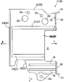
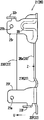
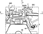
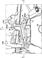
- FIG. 2 is a cross-sectional view taken along line II-II in FIG. 1 and is an enlarged cross-sectional view illustrating a part of the vehicle. It is the perspective view which looked at the auxiliary equipment for vehicles and its arrangement
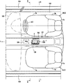
- FIG. 1 is a plan view showing the front of a passenger compartment of a vehicle equipped with a vehicle auxiliary machine and its arrangement structure according to the present embodiment
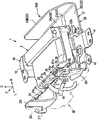
- FIG. FIG. 4 is a perspective view of the vehicular auxiliary device and its arrangement structure as seen from the rear left diagonally upper side
- FIG. 4 is a perspective view of the vehicular auxiliary device and its arrangement structure as seen from the upper right diagonal direction
- FIG. 6 is an exploded perspective view of the vehicle auxiliary machine and the vehicle auxiliary machine installation structure
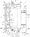
- FIG. 7 is a plan view of the protective bracket
- FIG. 8 is a left side view of the protective bracket.
- FIG. 9 is a front view of the protective bracket as viewed from the front
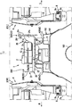
- FIG. 10 is a perspective view showing the main part of the configuration on the vehicle body side in the vicinity of the vehicle auxiliary machine arrangement structure of the present embodiment, and FIG. 11 is the vehicle auxiliary machine.
- FIG. 6 is an external view of a DCM bracket pedestal member on the vehicle body side that attaches and supports the arrangement structure.
- arrow F indicates the front of the vehicle
- arrow W indicates the vehicle width direction
- arrow R indicates the vehicle right side
- arrow L indicates the vehicle left side
- arrow U indicates the vehicle upper side.
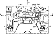
- the lower surface of the passenger compartment is constituted by a floor panel 100 extending substantially horizontally in the front-rear direction between a dash lower panel (not shown) and a rear kick-up portion.
- a tunnel portion 101 that protrudes upward (toward the vehicle interior) and extends in the front-rear direction of the vehicle is formed at the center of the floor panel 100 in the vehicle width direction.
- a tunnel member 102 that forms a closed cross-section with the tunnel portion 101 is joined to the upper portion of the tunnel portion 101.
- the tunnel member 102 is a vehicle body rigid member that extends in the vehicle front-rear direction along the upper portion of the tunnel portion 101.
- an exhaust pipe 103 provided as one of the exhaust system members of the engine is disposed in the lower space outside the vehicle of the tunnel portion 101.
- side sills 104 as vehicle body rigid members extending in the vehicle front-rear direction are joined to both ends of the floor panel 100 in the vehicle width direction.
- the front seat 3 is installed in a state where the front seat 3 is arranged in the vehicle width direction at the front portion of the floor panel 100, and the front seat 3 is disposed on the right side with respect to the tunnel portion 101 in the right-hand drive vehicle. And the front passenger seat 3L disposed on the left side of the tunnel portion 101.
- the driver's seat 3R and the passenger seat 3L are composed of left and right separate seats each having a seat cushion 3a, a seat back 3b, and a headrest 3c.
- a seat support structure 4 that supports a seat cushion 3a, a seat back 3b, and a headrest 3c is provided below the front seat 3.
- the seat support structure 4 extends in the vehicle front-rear direction with respect to the floor panel 100, and is provided with a slide mechanism 5 for supporting the seat cushion 3a in the seat front-rear direction (vehicle front-rear direction).
- This slide mechanism 5 is provided with a pair of left and right seats in the vehicle width direction of the front seat 3 (only one is shown in FIG. 2), and is slidable with respect to the pair of left and right seat rails 5a fixed to the floor panel 100 and the seat rails 5a.
- a slider 5b that engages with the slider 5b.
- the seat support structure 4 is interposed between the slider 5b of the slide mechanism 5 and the seat cushion 3a, and support brackets 6 for supporting the seat cushion 3a are provided on the left and right sides.
- the seat support structure 4 is provided with a bar-shaped (pipe-shaped) seat cushion frame 7 extending linearly in the vehicle width direction between the left and right support brackets 6. Both ends in the width direction are fixed to the corresponding support brackets 6 by welding or the like.
- the seat cushion frame 7 is not only a strength member that increases the rigidity of the lower portion of the front seat 3 but also a drive unit (one provided on the left and right sides) for driving a link member provided in a lifter mechanism (not shown). It may appropriately have a function as a stabilizer for transmitting the drive (not shown) to the other.
- an instrument panel 105 (instrument panel 105) extending in the vehicle width direction is disposed at the front of the vehicle interior of the vehicle, and both left and right front seats 3 (passenger seat 3L and driver seat) are disposed.
- 3R a center console 106 extending from the instrument panel 105 to the rear of the vehicle body is disposed so as to cover the tunnel member 102 extending in the front-rear direction from the vehicle compartment side (upper side).
- a steering wheel 107 is disposed in front of the driver's seat 3R.
- the center console 106 is provided with a shift knob 108.
- the shift knob 108 is attached to and supported by the tunnel member 102 via a shift knob mounting base member 50 (see FIG. 10) described later.
- the DCM unit 1 is disposed behind the shift knob 108.
- the DCM unit 1 includes a DCM (Data Communication Module) 2 as a vehicle auxiliary device according to the present embodiment and a DCM bracket 500, and a passenger seat 3L arranged in the vehicle width direction. Between the driver's seats 3 ⁇ / b> R, the vehicle is mounted and supported directly or indirectly on the tunnel member 102 via the DCM bracket pedestal member 40 while being covered by the center console 106 from the passenger compartment side (upper side). Yes.
- DCM Data Communication Module
- the DCM bracket pedestal member 40 includes a pedestal portion 41 and a plurality of tunnel member mounting flanges 42 (42f, 42r) extending downward from the pedestal portion 41 and outward in plan view. And is integrally formed of a steel plate.
- a rear tunnel member mounting flange 42r extending downward and rearward from the rear portion of the pedestal 41 among the plurality of tunnel member mounting flanges 42 has a mounting hole 42a formed therethrough, and the tunnel member 102 is bolted to the mounting hole 42a. Fastened and fixed using B1 and a nut (not shown).
- a front tunnel member mounting flange 42f that extends downward from the front portion of the pedestal portion 41 and extends to the left and right sides has a mounting hole 42a formed therethrough.
- the mounting base member 50 is fastened and fixed to the tunnel member 102 using bolts B2 and nuts (not shown). That is, as shown in FIG. 10, the rear side tunnel member mounting flange 42r is directly fastened and fixed to the tunnel member 102, whereas the front side tunnel member mounting flange 42f is interposed via the shift knob mounting base member 50. It is fastened and fixed to the tunnel member 102.
- the shift knob mounting base member 50 is fastened and fixed to the upper surface of the tunnel member 102 with bolts and nuts so that the front portion thereof is positioned in front of the DCM bracket base member 40.
- a front tunnel member mounting flange 42f is attached to a rear base surface 51r formed at the rear part thereof, and a front base base to which the shift knob 108 is attached is attached to the front part thereof.
- a surface 51f is formed.
- the shift knob mounting base member 50 serves not only for the shift knob 108 but also for mounting the front portion of the DCM bracket base member 40.
- the front and rear portions of the shift knob 108 are supported by two brackets from the front and rear sides, and the bracket that supports the rear portion of the shift knob 108 corresponds to the shift knob mounting base member 50. .
- a bracket that supports the front portion of the shift knob 108 is not shown.
- the DCM 2 is an in-vehicle emergency call device for transmitting information from a vehicle to a rescue organization. As shown in FIGS. 2 to 6, the DCM 2 is entirely covered by a housing, and the vehicle longitudinal direction with respect to the vehicle width direction. It has a three-dimensional shape that is substantially rectangular in plan view.
- the DCM 2 is an intermediate position in the vehicle width direction in which the left and right front seats 3R, 3L are arranged in the vehicle body side attached state supported by the DCM bracket base member 40 on the vehicle body side via the DCM bracket 500.
- one side surface of the left and right side surfaces of the DCM 2 in this embodiment, the left side surface (the side facing the passenger seat 3 ⁇ / b> L), A DCM-side connector 2a for connecting a harness-side connector 61a that is provided on one end side of the extending power supply and signal line harness 61 is provided.
- the harness connection part 29 is comprised in the connection part of the harness side connector 61a and the DCM side connector 2a.
- the harness connecting portion 29 is configured on one of the left and right side surfaces of the DCM 2 so that the longitudinal length of the DCM 2 that is longer in the longitudinal direction than in the width direction is not further increased.
- the DCM bracket 500 is mainly composed of two members, a DCM fixing bracket 10 for fixing the DCM 2 and a protective bracket 20 attached to the vehicle body side.
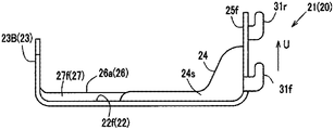
- the protective bracket 20 stands substantially perpendicularly to the base surface 22 from both outer ends in the vehicle width direction with respect to the base surface 22 constituting the bottom surface and the base surface 22.
- the left and right vertical wall portions 23 (23 ⁇ / b> A and 23 ⁇ / b> B) provided, and the rib 24 formed between the left vertical wall portion 23 ⁇ / b> A and the base surface 22 are provided.
- the left and right vertical wall portions 23 are separated from each other across the base surface 22 in the vehicle width direction.
- the vertical wall portion 23 ⁇ / b> A on the left side of the vehicle that is, the vertical wall portion 23 ⁇ / b> A on the side close to the harness connecting portion 29 (hereinafter referred to as “harness side vertical wall portion 23 ⁇ / b> A”). Further, it is erected substantially perpendicular to the base surface 22 so as to be interposed between the passenger seat 3L and the DCM 2 in the vehicle width direction.
- the harness side vertical wall portion 23A is formed higher than the right vertical wall portion 23B.
- the vertical wall portion 23B on the right side that is, the vertical wall portion 23B on the side far from the harness connecting portion 29 in the vehicle width direction (the side opposite to the vertical wall portion 23A with respect to DCM2 in the vehicle width direction)
- the vertical wall portion 23B is erected substantially perpendicular to the base surface 22 so as to be interposed between the driver's seat 3R and the DCM 2 in the vehicle width direction.
- the protective bracket 20 mainly includes a protective bracket body 21 having a base surface 22 and a non-harness side vertical wall portion 23B, and a harness side vertical wall portion 23A from the passenger seat 3L side. It consists of two members, a plate-like protection plate 28 corresponding to the shape viewed from the front.
- the left end portion of the base surface 22 of the protective bracket body 21 is provided with a front standing portion 25f and a rear standing portion 25r that rise substantially perpendicular to the base surface 22 from the front and rear ends. .
- the harness side vertical wall portion 23A is formed by the front side standing portion 25f and the rear side standing portion 25r and the protection plate 28.
- the front standing portion 25f is formed with a front engagement protrusion 31f that protrudes from the vertical middle portion of the front edge while bending forward, left, and upward in this order.
- the rear standing protrusion 25r is formed with a rear engagement protrusion 31r that protrudes from the upper part of the rear edge while bending backward, leftward, and upward in this order.
- the protection plate 28 is formed with a front-side engaged protrusion 32f that protrudes while being bent in this order from the vertical middle part of the front edge in this order, and the rear edge is rearward and downward from the upper part of the rear edge.
- a rear engaged protrusion 32r that protrudes while being bent in order is formed.
- the protective bracket 20 engages the front engaging protrusion 31f of the front standing portion 25f and the front engaged protrusion 32f of the protective plate 28 on each of the front and rear sides, and the rear standing portion 25r.
- the rear engagement protrusion 31r and the rear engagement protrusion 32r of the protective plate 28 are engaged with each other.
- the protection plate 28 can be temporarily fixed with respect to the protection bracket main body 21, ie, can be attached detachably.
- the protective bracket body 21 has body-side mounting holes 25a and 25b in the plate thickness direction (vehicle width direction) at the upper portions of the front-side standing portion 25f and the rear-side standing portion 25r.
- the protective plate 28 is provided at the upper and front and rear portions thereof, that is, when the protective plate 28 is engaged with the protective bracket main body 21, Protective plate side mounting holes 28a, 28b are formed penetratingly formed in the plate thickness direction at portions facing 25b.
- protection bracket main body 21 and the protection plate 28 are bolts B3 and nuts N3 in the main body side mounting holes 25a and 25b and the protective plate side mounting holes 28a and 28b on the front and rear sides (see FIGS. 4 and 5). It can be fastened and fixed using.
- the DCM unit 1 of the present embodiment is attached to the vehicle body side after assembling (assembling) the DCM 2, the DCM fixing bracket 10, and the protective bracket 20 together.
- the protective plate 28 is temporarily fixed to the protective bracket body 21 as described above, and then the bolt B3 and the nut are secured. It is attached using N3.
- the harness side vertical wall part 23A can be comprised in the left side surface of the DCM unit 1, and this harness side vertical wall part 23A is an assistant in a vehicle width direction, as shown in FIG. It can be interposed between the seat 3L and the DCM2.
- the part from the center part in the front-rear direction to the lower end part is one side in the plate thickness direction from the outer peripheral part of the part (left side in this example).
- a bulging portion 33 that bulges out is formed, and a bead 34 that forms a ridge line of the bulging portion 33 is formed on the periphery of the bulging portion 33 except for the lower end thereof.
- the bead 34 includes a front-rear direction bead 34 a extending along the vehicle front-rear direction.
- the front-rear direction bead 34a is a reinforcing portion that increases the strength of the protective bracket 20 against a part of the seat cushion 3a of the passenger seat 3L coming into contact with a side collision.
- the ribs 24 are arranged side by side in the vehicle front-rear direction, and these ribs 24 (the front ribs 24 and the rear ribs 24) are both front side standing portions.
- a corner portion (inner corner portion) between 25f and the base surface 22 is formed between them, and has a surface 24s parallel to the vehicle width direction and the vertical direction, that is, a surface 24s perpendicular to the front-rear direction.
- the rib 24 protrudes upward with respect to the upper surface of the front portion 22f over the entire length of the front portion 22f (base surface front portion 22f) of the base surface 22 in the vehicle width direction, and the vehicle left side portion is the front side. Projects to the right of the right side (inner side in the vehicle width direction) of the front side erected portion 25f until it reaches the main body side mounting hole 25a of the erected portion 25f, and is formed in a substantially inverted L shape when viewed from the rear of the vehicle. (See FIG. 2).
- a bead 35 extending vertically including a corner portion with the base surface 22 is provided on the rear side standing portion 25r (see FIGS. 4 and 6).
- the intermediate portion of the protective bracket body 21 in the front-rear direction of the base surface 22 is in relation to the upper surfaces of the front and rear portions (base surface front portion 22f and base surface rear portion 22r).
- a pedestal portion 26 is formed, and a flat pedestal surface 26 a on which the DCM fixing bracket 10 can be disposed is formed on the upper surface of the pedestal portion 26.
- the harness is located on the left side portion of the pedestal portion 41, and the portion corresponding to the inner side of the standing portions 25 f and 25 r on the front and rear sides in the vehicle width direction of the pedestal portion 41.
- a harness routing space Z that allows the harness 61 extending from the connection portion 29 (harness side connector 61a) to be routed downward is formed in a notch shape.
- a stepped portion 27 that protrudes in a stepped manner with respect to the front portion of the base surface 22 is formed on the front and rear sides of the base portion 41.
- These step portions 27 both extend linearly in the vehicle width direction, and the rear step portion 27r includes the non-harness side vertical wall portion 23B and the harness side vertical portion. It extends in the vehicle width direction so as to connect the wall portion 23A (rear side standing portion 25r).
- FIGS. 6 and 7 a total of three parts, that is, two parts spaced apart in the vehicle width direction at the rear part of the base surface rear part 22r and the front part from the rib 24 of the base surface front part 22f, that is, FIG.
- a mounting hole 22a is formed through the portion corresponding to the mounting hole 41a provided in the base portion 41 of the DCM bracket base member 40 shown in FIG.
- the protective bracket 20 is provided with the mounting hole 41a and the mounting hole 22a using bolts B4 (see FIG. 5) and nuts (not shown) in a state where the DCM fixing bracket 10 is disposed on the base part 41 of the DCM bracket base member 40. By fastening and fixing at, it is attached to the DCM bracket base member 40 on the vehicle body side.
- the DCM fixing bracket 10 includes a DCM mounting pedestal 11 ⁇ / b> A for attaching DCM 2 on the outer peripheral side of the DCM fixing bracket main body 11 formed in a substantially rectangular shape in plan view, and the DCM fixing bracket 10 as a protective bracket.
- the installation portion 11B installed on the pedestal surface 26a, the front ground flange portion 12 for connecting and fixing a ground terminal (not shown) arranged on the front side of the DCM 2, and the DCM fixing bracket main body portion 11 backward.
- a rear extending portion 13 that extends, a rear ground flange portion 14 for connecting and fixing a ground terminal (not shown) disposed on the rear side of the DCM 2, and a location near the DCM 2 that is not shown, except for the DCM 2.
- a clip mounting flange portion 15 for fixing a harness (not shown) connected to the vehicular auxiliary machine is integrally formed.
- the DCM mounting pedestal portion 11A is formed in a flat shape, and mounting holes 11a for fastening and fixing the DCM 2 using bolts and nuts are formed through the four corners.
- the through-hole 22b provided in the rear surface 22r of the base surface of the protective bracket 20 corresponding to the mounting hole 11a in a plan view is the above bolt used when the DCM2 is attached to the DCM mounting base 11A ( It is a service hole for insertion.
- the installation portion 11 ⁇ / b> B is formed in a concave shape downward with respect to the DCM mounting pedestal portion 11 ⁇ / b> A at the center portion of the DCM fixing bracket main body portion 11, and its lower surface (bottom surface) It is formed in a flat shape so that it can come into contact with the pedestal surface 26a in a surface contact state.
- the front-side grounding flange portion 12 is erected at a right angle from the front end of the DCM fixing bracket main body portion 11 to the DCM mounting pedestal portion 11A, and extends horizontally from the upper end to the rear.
- the rearward extending portion 13 is disposed above the base surface rear portion 22r of the protective bracket 20, and as shown in FIG. 5, the DCM fixing bracket main body portion bypasses the mounting hole 22a (see FIG. 7) in plan view. 11 extends horizontally from the rear end to the rear.
- the rear ground flange portion 14 and the clip mounting flange portion 15 are horizontally extended from the rear extension portion 13 to the respective sides on the rear and diagonally left sides.
- the DCM fixing bracket 10 is connected only to the vehicle body side, that is, the DCM bracket pedestal member 40 (see FIGS. 10 and 11) via the protective bracket 20 so that the side collision load is not directly transmitted from the vehicle body side at the time of a side collision.
- the DCM fixing bracket 10 is configured to be capable of relative displacement with respect to the protective bracket 20 when the protective bracket 20 is deformed (see FIG. 2).
- the lower surface of the installation portion 11B of the DCM fixing bracket 10 is in contact with the pedestal surface 26a of the protective bracket 20 while being in surface contact, and is welded to the pedestal surface 26a at the contact portion.
- the DCM fixing bracket 10 and the protective bracket 20 are fixed only by welding the lower surface of the installation part 11B and the pedestal surface 26a, and the DCM fixing bracket 10 is DCM fixed except for this welding point A.
- the bracket 10 is not fixed to the vehicle body side.
- the DCM fixing bracket 10 is configured to be relatively displaceable with respect to the protective bracket 20 by peeling off the lower surface of the installation portion 11B from the pedestal surface 26a of the protective bracket 20 at the time of a side collision.
- FIG. 12 is an operation explanatory view showing the initial state of the side collision corresponding to FIG. 2
- FIG. 13 is an operation explanatory view showing the state of the side collision corresponding to FIG. 2
- FIG. 3 is an operation explanatory view showing the operation corresponding to FIG. 2.
- the seat rail 5a of the passenger seat 3L is detached from the floor panel 100 from the state shown in FIG.
- the seat support structure 4 itself is deformed or the like and is displaced toward the inner side in the vehicle width direction, that is, toward the DCM unit 1 side.
- the inner end in the vehicle width direction of the bar-shaped seat cushion frame 7 of the seat support structure 4 of the passenger seat 3L that is displaced inward in the vehicle width direction is the harness side vertical wall. It directly contacts the portion 23A.
- the harness-side vertical wall portion 23A is received by the rib 24 so that it does not fall into the DCM 2 side, and the harness-side vertical wall portion 23A (protection plate 28) is not deformed itself in the front-rear direction bead 34a. Therefore, the side impact load from the seat support structure 4 of the passenger seat 3L can be firmly received.
- the protective bracket 20 that is, the base It is possible to prevent the DCM2 from receiving a side impact load directly from the seat support structure 4 of the passenger seat 3L without collapsing the arrangement space of the DCM2 constituted by the surface 22 and the pair of vertical wall portions 23A and 23B. it can.
- the DCM unit 1 includes the vehicle auxiliary machine arrangement structure in which the DCM 2 is arranged as the vehicle auxiliary machine between the front seats 3R and 3L arranged in the vehicle width direction in the vehicle body.
- the DCM 2 is attached and the DCM bracket 500 is fixed to the vehicle body.
- the DCM 2 has a harness connection portion 29 to which the harness 61 is connected, and is disposed so that the harness connection portion 29 is located on one front seat 3L (passenger seat 3L) side.
- a rib 24 extending between the harness-side vertical wall portion 23A and the base surface 22 in the harness-side vertical wall portion 23A on the side close to the harness connecting portion 29 of the DCM 2 among the pair of vertical wall portions 23A, 23B. Are formed (see FIGS. 2 to 7 and 9).
- the harness side vertical wall portion 23A can be supported by the rib 24 so that the harness side vertical wall portion 23A does not fall into the DCM 2 side at the time of a side collision, the harness side vertical wall portion 23A is supported by the rib 24.
- the harness connecting portion 29 can be more reliably protected than when not. Therefore, even if a part of the passenger seat 3L (for example, the seat cushion frame 7) comes into contact with the harness-side vertical wall portion 23A at the time of a side collision, the DCM 2 can function.
- the rib 24 is formed of a surface 24s parallel to the vehicle width direction (see FIGS. 2 to 4, 6, and 9).
- the harness-side vertical is formed by the ribs 24 formed from the surfaces 24s parallel to the vehicle width direction.
- the wall portion 23A can be prevented from falling down more reliably.
- the harness side vertical wall portion 23 ⁇ / b> A is a separate member from the DCM fixing bracket 10 and the protection bracket body 21, and is formed of a protection plate 28 that can be attached to and detached from the protection bracket body 21. (See FIGS. 3-6).
- the harness connecting portion 29 can be opened without being covered from the left side by the protective plate 28 by removing the protective plate 28 from the protective bracket main body 21 with the above configuration, so that the harness 61 is connected to the DCM 2.
- the protective plate 28 can be properly and easily connected without being obstructed, and the protective plate 28 is attached to the protective bracket body 21 when the vehicle is running (normal time), so that the passenger seat can be used in a side collision. Even if a part of 3L is displaced to the DCM 2 side, the harness connecting portion 29 can be protected by contacting the protective plate 28.
- the harness side vertical wall portion 23A is formed with a front and rear direction bead 34a as a reinforcing portion extending along the vehicle front and rear direction (see FIGS. 4 and 6).
- the harness-side vertical wall portion 23A against contact with a part of the passenger seat 3L at the time of a side collision is formed by forming the front-rear direction bead 34a as a reinforcing portion on the harness-side vertical wall portion 23A.
- Strength of the harness can be increased, and the protection performance of the harness connecting portion 29 by the harness-side vertical wall portion 23A can be enhanced.
- the base surface 22 is configured with a pedestal portion 26 that is raised with respect to the base surface 22, and a step portion 27 (27f extending in the vehicle width direction) is provided at the end of the pedestal portion 26. 27r) (see FIGS. 3 and 5 to 9).
- the compressive strength in the vehicle width direction of the base surface 22 can be increased by the pedestal portion 26 having the stepped portion 27 extending in the vehicle width direction at the end side.
- the shape of the base surface 22 can be maintained so as not to be crushed in the vehicle width direction and the distance between the vertical wall portions 23 is narrowed, so that the DCM 2 can be protected from being damaged.
- the base surface 22 is not relatively weakened by providing the rib 24 to reinforce the harness side vertical wall portion 23A, and the base portion 22 is also reinforced by the stepped portion 27. Therefore, the DCM 2 can be protected by the vertical wall portion 23 and the base surface 22 against a side collision.
- the harness connection part 29 may be provided on the right side (driver's seat 3R side). That is, the harness-side vertical wall portion 23A and the non-harness-side vertical wall portion 23B may be provided in the left-right direction.
- the arrangement structure of the vehicular auxiliary machine according to the present disclosure is not limited to the structure in which the vehicular auxiliary machine is arranged between the front seats arranged in the vehicle width direction, and for example, the vehicular auxiliary machine is arranged between the rear seats arranged in the vehicle width direction. You may apply to the structure which arrange
- An arrangement structure of a vehicular auxiliary machine is provided with the vehicular auxiliary machine arranged between seats arranged in the vehicle width direction in the vehicle body and the vehicular auxiliary machine. And a bracket fixed to the vehicle body and a harness connected to the vehicular auxiliary machine, the vehicular auxiliary machine has a harness connection part to which the harness is connected and the harness connection part is one side The bracket is erected with respect to the base surface so as to be separated from each other in the vehicle width direction between the base surface and the vehicle auxiliary machine and each seat. A pair of vertical wall portions and a harness-side vertical wall portion of the pair of vertical wall portions closer to the harness connecting portion of the vehicular accessory, between the harness-side vertical wall portion and the base surface. And a rib extending over.
- the vehicular auxiliary machine directly interferes with the seat in a side collision. Specifically, it is possible to reliably protect the vehicular auxiliary machine at the time of a side collision (at the time of a side collision).
- the harness connecting portion is more reliably protected by the harness side vertical wall portion and the rib. Can function.
- the arrangement structure of the vehicular auxiliary machine according to another aspect of the present disclosure is the above-described aspect, and the rib is configured with a surface parallel to the vehicle width direction.
- the harness-side vertical wall portion can be more reliably prevented from falling due to the seat coming into contact with the harness-side vertical wall portion at the time of a side collision.
- An arrangement structure of a vehicular auxiliary machine is the above aspect, wherein the harness-side vertical wall portion is a separate member from the bracket and is attachable to and detachable from the bracket. including.
- the harness connecting portion can be exposed without being covered by the protective plate, so that the protective plate becomes an obstacle when the harness is connected to the vehicle auxiliary machine. And can be connected appropriately and easily.
- the arrangement structure of the vehicular auxiliary machine according to another aspect of the present disclosure is the above aspect, and the harness-side vertical wall portion includes a reinforcing portion formed so as to extend along the vehicle front-rear direction.
- the reinforcing portion on the harness-side vertical wall portion, it is possible to increase the strength of the harness-side vertical wall portion against the contact of the seat at the time of a side collision, and the harness connecting portion by the harness-side vertical wall portion Can improve the protection performance.
- the reinforcing part is, for example, a step part (ridge line part) extending along the vehicle longitudinal direction, a concave or convex bead, a rib (thick part), or a combination of at least one of these. Etc. can be formed.
- An arrangement structure of a vehicular auxiliary machine is the above aspect, wherein the base surface includes a pedestal portion formed so as to protrude from the base surface, and the pedestal portion Has a step portion formed on the end side of the pedestal portion so as to extend in the vehicle width direction.
- the strength in the vehicle width direction of the base surface can be increased by the stepped portion provided in the edge of the pedestal portion and extending in the vehicle width direction, the base surface is crushed in the vehicle width direction at the time of a side collision.
- the shape of the base surface can be maintained so that the interval between the vertical wall portions is not narrowed, and thus the vehicle auxiliary machine can be protected from being damaged.
- the base surface is not relatively weakened by reinforcing the base surface by the stepped portion.
- the vehicle auxiliary machine can be protected by the portion and the base surface.
- An arrangement structure of a vehicular auxiliary machine is provided with the vehicular auxiliary machine arranged between seats arranged in the vehicle width direction in the vehicle body and the vehicular auxiliary machine. And a bracket fixed to the vehicle body, the bracket including an auxiliary machine fixing bracket to which the vehicle auxiliary machine is fixed, and a protective bracket having a vertical wall portion between the seat and the vehicle auxiliary machine.
- the accessory fixing bracket is configured to be capable of relative displacement with respect to the protective bracket when the protective bracket is deformed by the contact of the seat.
- the accessory fixing bracket can be displaced with respect to the protective bracket. It is possible to prevent damage to the vehicle auxiliary machine itself.
- An arrangement structure of an auxiliary machine for a vehicle according to another aspect of the present disclosure is the above-described aspect, wherein the auxiliary equipment fixing bracket protects the vehicle body from the side collision load from the vehicle body side. It is fixed only via the bracket.
- the auxiliary machine fixing bracket is fixed to the vehicle body only through the protective bracket so that the side collision load is not transmitted from the vehicle body.
- the side impact load is not directly transmitted from the vehicle body to the accessory fixing bracket, so that the vehicle accessory itself can be prevented from being damaged by the side impact load.
- the arrangement structure of the vehicular auxiliary machine according to another aspect of the present disclosure is the above-described aspect, and the auxiliary machine fixing bracket is fixed to the protective bracket so as to be peelable by welding.
- the auxiliary equipment fixing bracket is peeled off from the protective bracket by using the impact caused by the seat coming into contact with the bracket at the time of a side collision, so that the auxiliary equipment fixing bracket is not fixed to the protective bracket and can be relatively displaced. Therefore, it is possible to prevent damage to the vehicular auxiliary machine itself without excessive shock caused by a side collision being applied to the auxiliary machine fixing bracket.
- the possibility that the vehicle auxiliary machine directly interferes with the seat at the time of a side collision can be reduced.
Abstract
Selon la présente invention, un accessoire de véhicule est disposé dans un corps de véhicule entre des sièges côte à côte dans le sens de la largeur du véhicule. L'accessoire de véhicule est fixé à un support, lequel est fixé au corps de véhicule. L'accessoire de véhicule comprend une partie de raccordement de harnais disposée de façon à être positionnée vers un siège. Le support comporte une surface de base et deux parties de paroi verticales. De plus, le support comporte une nervure qui passe entre la partie de raccordement de harnais et la surface de base sur la partie de paroi verticale côté harnais, qui est le côté le plus proche de la partie de raccordement de harnais parmi les deux parties de paroi verticales.
Priority Applications (4)
| Application Number | Priority Date | Filing Date | Title |
|---|---|---|---|
| EP18757666.5A EP3572289B1 (fr) | 2017-02-22 | 2018-02-06 | Structure d'agencement d'une machine auxiliaire pour véhicule |
| CN201880012945.1A CN110325404B (zh) | 2017-02-22 | 2018-02-06 | 车用附属装置的设置结构 |
| US16/486,978 US11491922B2 (en) | 2017-02-22 | 2018-02-06 | Arrangement structure of auxiliary machine for vehicle |
| RU2019128446A RU2720587C1 (ru) | 2017-02-22 | 2018-02-06 | Размещаемая конструкция вспомогательного устройства для транспортного средства |
Applications Claiming Priority (2)
| Application Number | Priority Date | Filing Date | Title |
|---|---|---|---|
| JP2017030639A JP6380574B2 (ja) | 2017-02-22 | 2017-02-22 | 車両用補機の配設構造 |
| JP2017-030639 | 2017-02-22 |
Publications (1)
| Publication Number | Publication Date |
|---|---|
| WO2018155152A1 true WO2018155152A1 (fr) | 2018-08-30 |
Family
ID=63254286
Family Applications (1)
| Application Number | Title | Priority Date | Filing Date |
|---|---|---|---|
| PCT/JP2018/003889 WO2018155152A1 (fr) | 2017-02-22 | 2018-02-06 | Structure de disposition d'accessoire pour véhicule |
Country Status (6)
| Country | Link |
|---|---|
| US (1) | US11491922B2 (fr) |
| EP (1) | EP3572289B1 (fr) |
| JP (1) | JP6380574B2 (fr) |
| CN (1) | CN110325404B (fr) |
| RU (1) | RU2720587C1 (fr) |
| WO (1) | WO2018155152A1 (fr) |
Citations (8)
| Publication number | Priority date | Publication date | Assignee | Title |
|---|---|---|---|---|
| JP2003527726A (ja) * | 1998-07-15 | 2003-09-16 | トーマス アンド ベッツ インターナショナル,インク. | エアバッグ・ガス・ジェネレータ用コネクタ |
| JP2005112083A (ja) * | 2003-10-06 | 2005-04-28 | Denso Corp | エアバッグecu |
| JP2007099029A (ja) * | 2005-10-03 | 2007-04-19 | Nissan Motor Co Ltd | ユニット取付構造 |
| JP2008213714A (ja) | 2007-03-06 | 2008-09-18 | Denso Corp | 車載緊急通報装置 |
| JP2009234379A (ja) | 2008-03-26 | 2009-10-15 | Toyota Motor Corp | 衝突検知構造及び乗員保護システム |
| JP2013119326A (ja) * | 2011-12-07 | 2013-06-17 | Honda Motor Co Ltd | 電装部品の保護構造 |
| WO2017002191A1 (fr) * | 2015-06-30 | 2017-01-05 | 本田技研工業株式会社 | Console d'unité de commande électronique et véhicule |
| JP2017193296A (ja) * | 2016-04-22 | 2017-10-26 | マツダ株式会社 | 緊急通報装置の配設構造 |
Family Cites Families (15)
| Publication number | Priority date | Publication date | Assignee | Title |
|---|---|---|---|---|
| JP3726277B2 (ja) * | 1997-01-30 | 2005-12-14 | マツダ株式会社 | 車両用エアバックシステム |
| US6663411B2 (en) | 1998-07-15 | 2003-12-16 | Tyco Electronics Logistics Ag | Clamshell connector for airbag gas generator |
| JP2005238990A (ja) * | 2004-02-26 | 2005-09-08 | Denso Corp | 加速度センサの取付構造 |
| ATE554974T1 (de) | 2008-03-26 | 2012-05-15 | Toyota Motor Co Ltd | Struktur und system zur aufprallerkennung |
| DE102008040157A1 (de) * | 2008-07-03 | 2010-01-07 | Robert Bosch Gmbh | Steuergerät für Personenschutzmittel für ein Fahrzeug bzw. Verfahren zum Zusammenbau eines solchen Steuergeräts |
| DE112009004801B4 (de) * | 2009-05-28 | 2018-08-30 | Toyota Jidosha Kabushiki Kaisha | Brennstoffzellensystem und fahrzeug |
| DE112009004806B4 (de) * | 2009-05-28 | 2018-03-22 | Toyota Jidosha Kabushiki Kaisha | Brennstoffzellensystem und -fahrzeug |
| JP4924665B2 (ja) * | 2009-06-11 | 2012-04-25 | 日産自動車株式会社 | 車体の後部構造 |
| US9033399B2 (en) * | 2010-03-01 | 2015-05-19 | Sabic Global Technologies B.V. | Energy absorber elements and vehicle systems |
| CN103781667B (zh) * | 2011-10-24 | 2016-05-18 | 本田技研工业株式会社 | 电动车辆的配线保护罩构造 |
| GB2500599B (en) * | 2012-03-26 | 2017-08-16 | Ford Global Tech Llc | Vehicle seat assembly |
| US10150440B2 (en) * | 2016-05-19 | 2018-12-11 | Ford Global Technologies, Llc | Restraints control module attachment assembly |
| JP6702061B2 (ja) * | 2016-07-28 | 2020-05-27 | 三菱自動車工業株式会社 | 車体構造 |
| CN106891906B (zh) * | 2017-03-22 | 2018-12-11 | 青岛欧特美交通装备有限公司 | 一种具有垂向缓冲功能的一片式侧护板装置 |
| US11027680B2 (en) * | 2018-12-13 | 2021-06-08 | Ford Global Technologies, Llc | Vehicle tracks |
-
2017
- 2017-02-22 JP JP2017030639A patent/JP6380574B2/ja active Active
-
2018
- 2018-02-06 EP EP18757666.5A patent/EP3572289B1/fr active Active
- 2018-02-06 US US16/486,978 patent/US11491922B2/en active Active
- 2018-02-06 WO PCT/JP2018/003889 patent/WO2018155152A1/fr unknown
- 2018-02-06 CN CN201880012945.1A patent/CN110325404B/zh active Active
- 2018-02-06 RU RU2019128446A patent/RU2720587C1/ru active
Patent Citations (8)
| Publication number | Priority date | Publication date | Assignee | Title |
|---|---|---|---|---|
| JP2003527726A (ja) * | 1998-07-15 | 2003-09-16 | トーマス アンド ベッツ インターナショナル,インク. | エアバッグ・ガス・ジェネレータ用コネクタ |
| JP2005112083A (ja) * | 2003-10-06 | 2005-04-28 | Denso Corp | エアバッグecu |
| JP2007099029A (ja) * | 2005-10-03 | 2007-04-19 | Nissan Motor Co Ltd | ユニット取付構造 |
| JP2008213714A (ja) | 2007-03-06 | 2008-09-18 | Denso Corp | 車載緊急通報装置 |
| JP2009234379A (ja) | 2008-03-26 | 2009-10-15 | Toyota Motor Corp | 衝突検知構造及び乗員保護システム |
| JP2013119326A (ja) * | 2011-12-07 | 2013-06-17 | Honda Motor Co Ltd | 電装部品の保護構造 |
| WO2017002191A1 (fr) * | 2015-06-30 | 2017-01-05 | 本田技研工業株式会社 | Console d'unité de commande électronique et véhicule |
| JP2017193296A (ja) * | 2016-04-22 | 2017-10-26 | マツダ株式会社 | 緊急通報装置の配設構造 |
Non-Patent Citations (1)
| Title |
|---|
| See also references of EP3572289A4 |
Also Published As
| Publication number | Publication date |
|---|---|
| US20200231098A1 (en) | 2020-07-23 |
| EP3572289B1 (fr) | 2021-05-05 |
| CN110325404A (zh) | 2019-10-11 |
| RU2720587C1 (ru) | 2020-05-12 |
| US11491922B2 (en) | 2022-11-08 |
| EP3572289A4 (fr) | 2019-12-04 |
| CN110325404B (zh) | 2021-12-21 |
| EP3572289A1 (fr) | 2019-11-27 |
| JP2018134973A (ja) | 2018-08-30 |
| JP6380574B2 (ja) | 2018-08-29 |
Similar Documents
| Publication | Publication Date | Title |
|---|---|---|
| EP2045170B1 (fr) | Structure avant pour automobile | |
| US7900983B2 (en) | Underrun protector mounting structure of vehicle | |
| EP1749731B1 (fr) | Structure arrière de véhicule automobile, et une méthode de montage | |
| US8851520B2 (en) | Front subframe for a narrow offset collision | |
| US7631926B2 (en) | Side impact crash event body structure improvement | |
| US8020925B2 (en) | Front structure of cab-over type vehicle | |
| JP2009083687A (ja) | 自動車の前部構造 | |
| JP3930004B2 (ja) | センサ配設構造 | |
| JP2021075089A (ja) | 車両下部構造 | |
| JP6551435B2 (ja) | 車両用補機の配設構造 | |
| JP4635467B2 (ja) | 自動車の衝突検知センサ配設構造 | |
| WO2018155152A1 (fr) | Structure de disposition d'accessoire pour véhicule | |
| JP4894613B2 (ja) | 車両のバンパー取付構造 | |
| JP4862575B2 (ja) | 車体後部構造 | |
| JP5852623B2 (ja) | 車体構造 | |
| JP2008302911A (ja) | 車体構造 | |
| JPS63176715A (ja) | 自動車の空調ユニツトの構造 | |
| JP3923801B2 (ja) | 車両のエアバッグセンサ取付構造 | |
| JP2019093855A (ja) | 衝突検出装置 | |
| JP3497394B2 (ja) | 衝突検出センサーの取付部構造 | |
| KR101755450B1 (ko) | 차량용 후방 프레임 유닛 | |
| JP3726464B2 (ja) | キャブオーバ車両の衝突安全車体構造 | |
| JP2013023084A (ja) | 車両の前部車体構造 | |
| JP2006130945A (ja) | 車両の後側面部構造 | |
| JP5477680B2 (ja) | 車体の前部構造 |
Legal Events
| Date | Code | Title | Description |
|---|---|---|---|
| 121 | Ep: the epo has been informed by wipo that ep was designated in this application |
Ref document number: 18757666 Country of ref document: EP Kind code of ref document: A1 |
|
| NENP | Non-entry into the national phase |
Ref country code: DE |
|
| ENP | Entry into the national phase |
Ref document number: 2018757666 Country of ref document: EP Effective date: 20190823 |