EP2043116B1 - Method for pretreating electrochemical capacitor negative electrode, method for manufacturing the electrochemical capacitor negative electrode, and method for manufacturing electrochemical capacitor using the method for manufacturing the electrochemical capacitor negative electrode - Google Patents
Method for pretreating electrochemical capacitor negative electrode, method for manufacturing the electrochemical capacitor negative electrode, and method for manufacturing electrochemical capacitor using the method for manufacturing the electrochemical capacitor negative electrode Download PDFInfo
- Publication number
- EP2043116B1 EP2043116B1 EP07790607A EP07790607A EP2043116B1 EP 2043116 B1 EP2043116 B1 EP 2043116B1 EP 07790607 A EP07790607 A EP 07790607A EP 07790607 A EP07790607 A EP 07790607A EP 2043116 B1 EP2043116 B1 EP 2043116B1
- Authority
- EP
- European Patent Office
- Prior art keywords
- layer
- negative electrode
- lithium
- electrode
- substrate
- Prior art date
- Legal status (The legal status is an assumption and is not a legal conclusion. Google has not performed a legal analysis and makes no representation as to the accuracy of the status listed.)
- Not-in-force
Links
Images


Classifications
-
- H—ELECTRICITY
- H01—ELECTRIC ELEMENTS
- H01G—CAPACITORS; CAPACITORS, RECTIFIERS, DETECTORS, SWITCHING DEVICES, LIGHT-SENSITIVE OR TEMPERATURE-SENSITIVE DEVICES OF THE ELECTROLYTIC TYPE
- H01G9/00—Electrolytic capacitors, rectifiers, detectors, switching devices, light-sensitive or temperature-sensitive devices; Processes of their manufacture
- H01G9/0029—Processes of manufacture
-
- H—ELECTRICITY
- H01—ELECTRIC ELEMENTS
- H01G—CAPACITORS; CAPACITORS, RECTIFIERS, DETECTORS, SWITCHING DEVICES, LIGHT-SENSITIVE OR TEMPERATURE-SENSITIVE DEVICES OF THE ELECTROLYTIC TYPE
- H01G11/00—Hybrid capacitors, i.e. capacitors having different positive and negative electrodes; Electric double-layer [EDL] capacitors; Processes for the manufacture thereof or of parts thereof
- H01G11/22—Electrodes
- H01G11/30—Electrodes characterised by their material
- H01G11/50—Electrodes characterised by their material specially adapted for lithium-ion capacitors, e.g. for lithium-doping or for intercalation
-
- H—ELECTRICITY
- H01—ELECTRIC ELEMENTS
- H01M—PROCESSES OR MEANS, e.g. BATTERIES, FOR THE DIRECT CONVERSION OF CHEMICAL ENERGY INTO ELECTRICAL ENERGY
- H01M10/00—Secondary cells; Manufacture thereof
- H01M10/05—Accumulators with non-aqueous electrolyte
- H01M10/052—Li-accumulators
-
- H—ELECTRICITY
- H01—ELECTRIC ELEMENTS
- H01M—PROCESSES OR MEANS, e.g. BATTERIES, FOR THE DIRECT CONVERSION OF CHEMICAL ENERGY INTO ELECTRICAL ENERGY
- H01M4/00—Electrodes
- H01M4/02—Electrodes composed of, or comprising, active material
- H01M4/04—Processes of manufacture in general
-
- H—ELECTRICITY
- H01—ELECTRIC ELEMENTS
- H01M—PROCESSES OR MEANS, e.g. BATTERIES, FOR THE DIRECT CONVERSION OF CHEMICAL ENERGY INTO ELECTRICAL ENERGY
- H01M4/00—Electrodes
- H01M4/02—Electrodes composed of, or comprising, active material
- H01M4/13—Electrodes for accumulators with non-aqueous electrolyte, e.g. for lithium-accumulators; Processes of manufacture thereof
-
- Y—GENERAL TAGGING OF NEW TECHNOLOGICAL DEVELOPMENTS; GENERAL TAGGING OF CROSS-SECTIONAL TECHNOLOGIES SPANNING OVER SEVERAL SECTIONS OF THE IPC; TECHNICAL SUBJECTS COVERED BY FORMER USPC CROSS-REFERENCE ART COLLECTIONS [XRACs] AND DIGESTS
- Y02—TECHNOLOGIES OR APPLICATIONS FOR MITIGATION OR ADAPTATION AGAINST CLIMATE CHANGE
- Y02E—REDUCTION OF GREENHOUSE GAS [GHG] EMISSIONS, RELATED TO ENERGY GENERATION, TRANSMISSION OR DISTRIBUTION
- Y02E60/00—Enabling technologies; Technologies with a potential or indirect contribution to GHG emissions mitigation
- Y02E60/10—Energy storage using batteries
-
- Y—GENERAL TAGGING OF NEW TECHNOLOGICAL DEVELOPMENTS; GENERAL TAGGING OF CROSS-SECTIONAL TECHNOLOGIES SPANNING OVER SEVERAL SECTIONS OF THE IPC; TECHNICAL SUBJECTS COVERED BY FORMER USPC CROSS-REFERENCE ART COLLECTIONS [XRACs] AND DIGESTS
- Y02—TECHNOLOGIES OR APPLICATIONS FOR MITIGATION OR ADAPTATION AGAINST CLIMATE CHANGE
- Y02E—REDUCTION OF GREENHOUSE GAS [GHG] EMISSIONS, RELATED TO ENERGY GENERATION, TRANSMISSION OR DISTRIBUTION
- Y02E60/00—Enabling technologies; Technologies with a potential or indirect contribution to GHG emissions mitigation
- Y02E60/13—Energy storage using capacitors
-
- Y—GENERAL TAGGING OF NEW TECHNOLOGICAL DEVELOPMENTS; GENERAL TAGGING OF CROSS-SECTIONAL TECHNOLOGIES SPANNING OVER SEVERAL SECTIONS OF THE IPC; TECHNICAL SUBJECTS COVERED BY FORMER USPC CROSS-REFERENCE ART COLLECTIONS [XRACs] AND DIGESTS
- Y02—TECHNOLOGIES OR APPLICATIONS FOR MITIGATION OR ADAPTATION AGAINST CLIMATE CHANGE
- Y02P—CLIMATE CHANGE MITIGATION TECHNOLOGIES IN THE PRODUCTION OR PROCESSING OF GOODS
- Y02P70/00—Climate change mitigation technologies in the production process for final industrial or consumer products
- Y02P70/50—Manufacturing or production processes characterised by the final manufactured product
-
- Y—GENERAL TAGGING OF NEW TECHNOLOGICAL DEVELOPMENTS; GENERAL TAGGING OF CROSS-SECTIONAL TECHNOLOGIES SPANNING OVER SEVERAL SECTIONS OF THE IPC; TECHNICAL SUBJECTS COVERED BY FORMER USPC CROSS-REFERENCE ART COLLECTIONS [XRACs] AND DIGESTS
- Y02—TECHNOLOGIES OR APPLICATIONS FOR MITIGATION OR ADAPTATION AGAINST CLIMATE CHANGE
- Y02T—CLIMATE CHANGE MITIGATION TECHNOLOGIES RELATED TO TRANSPORTATION
- Y02T10/00—Road transport of goods or passengers
- Y02T10/60—Other road transportation technologies with climate change mitigation effect
- Y02T10/70—Energy storage systems for electromobility, e.g. batteries
Definitions
- the present invention relates to a method for manufacturing an electrochemical capacitor used for various electronic equipment, a backup power source, regeneration of hybrid cars, fuel cell cars, electric power storage, or the like. More particularly, it relates to a method for pretreating such a negative electrode of an electrochemical capacitor and a method for manufacturing such a negative electrode.
- An electric double layer capacitor has a high withstand voltage, a large capacitance, and a high reliability with respect to rapid charge and discharge. Therefore, it is used in many fields.
- a polarizable electrode mainly including activated carbon is used for positive and negative electrodes of a general electric double layer capacitor.
- the withstand voltage of an electric double layer capacitor is 1.2 V when an aqueous electrolyte solution is used and 2.5 - 3.3 V when an organic electrolyte solution is used. Since the energy of an electric double layer capacitor is in proportion to the square of the withstand voltage, energy is higher when an organic electrolyte solution having a high withstand voltage is used than when an aqueous electrolyte solution is used.
- the energy density of an electric double layer capacitor using an organic electrolyte solution is 1/10 or less of that of a secondary battery such as a lead storage battery. Therefore, further improvement of the energy density is necessary.
- an electric double layer capacitor in which an electrode using a carbon material capable of absorbing and releasing lithium ions is used as a negative electrode and this carbon material is allowed to absorb a lithium ion in advance.
- Such an electric double layer capacitor is disclosed in, for example, Patent Document 1. Note here that this capacitor uses a polarizable electrode as a positive electrode, and the polarizable electrode mainly includes activated carbon.
- a method for allowing a negative electrode to absorb a lithium ion the following three methods are disclosed.
- the above-mentioned electric double layer capacitor has an advantage of having a high withstand voltage and a large capacitance, and is capable of carrying out rapid charge and discharge.
- an operation for allowing a carbon material to absorb lithium ions by a chemical or electrochemical method in advance is complicated, and much man-hour or cost is required.
- the carbon material is capable of absorbing and releasing lithium ions. Furthermore, it is difficult to obtain an excellent performance stably.
- a lithium ion secondary battery has been developed as a power source capable of charging and discharging a large electric current.
- a lithium ion battery has a higher voltage and higher capacity as compared with an electric double layer capacitor.
- a lithium ion battery has a higher resistance and remarkably short lifetime by a charge and discharge cycle in a large current as compared with an electric double layer capacitor.
- the document US 5,953,204 discloses a method of forming a double layer capacitor having a positive electrode and a negative electrode.
- the positive electrode has a current collector combined with a polarizable electrode material composed mainly of activated carbon
- the negative electrode has a current collector of porous metal incapable of forming an alloy with lithium, combined with a carbonaceous material having lithium ions occluded by a chemical method or an electrochemical method to a carbon material capable of occluding and releasing a lithium ions, and a nonaqueous electrolyte containing a lithium salt.
- the negative electrode is supported on a current collector of porous metal having a thickness of 0.1 to 1 mm and a porosity of 5 to 80%.
- the present invention provides a pretreating method as defined by the features of claim 1 for allowing a negative electrode of an electrochemical capacitor to absorb a lithium ion, the negative electrode using a material capable of reversibly absorbing and releasing lithium ions; a method according to claim 5 for manufacturing a negative electrode of an electrochemical capacitor by using the pretreating method; and a method being defined by the features of claim 6 for manufacturing an electrochemical capacitor.
- the method as defined by the features of claim 1 for pretreating an electrochemical capacitor negative electrode in accordance with the present invention includes the following two steps:
- step (C) is carried out prior to the above-mentioned steps (A) and (B):
- step (D) is carried out in addition to the above-mentioned steps (A) to (C).
- a lithium layer is formed on the surface of the electrode layer of the negative electrode by decal transferring.
- the electrode layer including the carbon material is in a state in which it immediately absorbs lithium ions before the negative electrode is combined with a positive electrode. Therefore, it is not necessary to provide a post-process for allowing the negative electrode to absorb lithium ions, thus improving productivity. Furthermore, a state in which lithium ions are absorbed by the electrode layer of the negative electrode is stabilized. Thus, an electrochemical capacitor having an excellent performance can be produced stably.
- Fig. 1 is a partially cut-away perspective view showing a configuration of an electrochemical capacitor in accordance with an exemplary embodiment of the present invention.
- Figs. 2A and 2B are conceptual diagrams showing a state in which the electrochemical capacitor is discharged and charged, respectively.
- This electrochemical capacitor includes element 1, case 8, sealing rubber 10 and electrolyte solution 9.
- Element 1 includes negative electrode 21, positive electrode 22 and separator 6. Separator 6 is disposed between negative electrode 21 and positive electrode 22 and prevents negative electrode 21 and positive electrode 22 from being brought into contact with each other.
- Negative electrode 21 includes current collector 4 as a first current collector that does not react with lithium, and electrode layers 5 formed on both surfaces of current collector 4.
- Current collector 4 is, for example, a copper foil.
- Electrode layer 5 includes a carbon material capable of reversibly absorbing and releasing lithium ions. As such a carbon material, for example, a well-known material such as graphite can be used.
- Positive electrode 22 includes current collector 2 as a second current collector that does not react with lithium, and polarizable electrode layers 3 formed on both surfaces of current collector 2.
- Current collector 2 is, for example, an aluminum foil.
- Electrode layer 3 mainly includes activated carbon.
- Lead wires 7A and 7B are coupled to negative electrode 21 and positive electrode 22, respectively.
- Lead wire 7A is formed of nickel or copper, and lead wire 7B is formed of aluminum.
- Element 1 is contained in case 8 together with electrolyte solution 9. An opening of case 8 is processed after sealing rubber 10 is inserted. Thus, case 8 is sealed. Lead wires 7A and 7B are drawn out from through holes provided in sealing rubber 10 toward the outside of case 8.
- Case 8 is made of, for example, aluminum. Sealing rubber 10 is made of, for example, fluororubber.
- Electrolyte solution 9 includes lithium ions 41 and anions 42 such as BF 4 - .
- lithium ions 41 are released from a carbon material included in negative electrode 21, and anions 42 are released from activated carbon included in positive electrode 22.
- lithium ions 41 are absorbed between layers of the carbon material included in negative electrode 21, and anions 42 are adsorbed to the activated carbon included in positive electrode 22. Due to the movement of charges according to such a movement of the ions, an electrochemical capacitor is charged and discharged. In such a system, negative electrode 21 absorbs lithium ions 41 and thus the electric potential is reduced, so that the voltage of the capacitor is increased. Thus, an energy density is improved.
- a procedure for producing positive electrode 22 is described.
- a 30 ⁇ m-thick aluminum foil with high purity (Al: 99.99% or more) is used as current collector 2.
- This Al foil is etched in a hydrochloric acid-based etching solution so that the surface is roughened.
- a paste is prepared.
- an activated carbon powder for example, phenolic resin-based activated carbon powder having an average particle diameter of 5 ⁇ m is used.
- a conductive agent for example, carbon black having an average particle diameter of 0.05 ⁇ m is used.
- an aqueous binder solution for example, an aqueous solution of carboxymethylcellulose (hereinafter, referred to as "CMC" is used.
- CMC carboxymethylcellulose
- This paste is coated on both surfaces of current collector 2 and dried in the air at 100°C for one hour. Thus, electrode layers 3 are formed. Thereafter, this positive electrode precursor is cut into a predetermined size and lead wire 7B is coupled to current collector 2. Thus, positive electrode 22 is completed.
- a procedure for producing negative electrode 21 is described.
- a 15 ⁇ m-thick copper foil is used as current collector 4.
- a paste is prepared for forming electrode layer 3.
- the carbon material capable of reversibly absorbing and releasing lithium ions for example, graphite is used.
- the conductive agent for example, acetylene black is used.
- the binder for example, polytetrafluoroethylene (hereinafter, referred to as "PTFE") and CMC are used in a weight ratio of 8 : 2.
- PTFE polytetrafluoroethylene
- CMC binder
- graphite, conductive agent and binder are used in a weight ratio of 80 : 10 : 10.
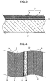
- Fig. 3 is an enlarged sectional view showing a state in which lithium layer 11 is transferred to negative electrode 21.
- Fig. 4 is an enlarged sectional view showing element 1 in a state before electrolyte solution 9 is filled.
- Lithium layer 11 having a thickness of 3 ⁇ m is formed on substrate 31 made of polypropylene (hereinafter, referred to as "PP") having a thickness of 0.1 mm by using a vapor deposition device.
- PP polypropylene
- Fig. 3 lithium layer 11 formed on substrate 31 is transferred to electrode layer 5 formed on negative electrode 21.
- electrode layer 5 formed on negative electrode 21.
- 3 ⁇ m-thick lithium layer 11 is formed on electrode layer 5.
- lithium layer 11 is formed on another of electrode layers 5. The above-mentioned operation is carried out under a dry atmosphere so that lithium layer 11 is not deformed.
- the effect obtained by forming lithium layer 11 and allowing negative electrode 21 to absorb a lithium ion (providing negative electrode 21 with lithium) in advance is utterly different between in a lithium ion secondary battery and in a capacitor, which is described.
- An object of providing a negative electrode with lithium in a lithium ion secondary battery is to improve charging and discharging capacity by reducing an irreversible capacity of the negative electrode.
- the ratio of the irreversible capacity with respect to the negative electrode capacity is about 0% to 20%. Therefore, lithium in an amount corresponding to at most about 20% of the negative electrode capacity may be provided to the negative electrode.
- an object of allowing negative electrode 21 to absorb lithium ions in advance is to increase the voltage of the capacitor by reducing an electric potential of negative electrode 21.
- the electric potential of positive electrode 22 is reduced as much as possible, the reaction of positive electrode 22 with respect to electrolyte solution 9 can be suppressed, thus enabling the lifetime of the capacitor to be improved. Therefore, when activated carbon is used for positive electrode 22, the electric potential of positive electrode 22 is set to, for example, 4.0 V, on the basis of the oxidation-reduction potential of lithium. In order to set the voltage of the capacitor to be at least 3.8 V or more by using such positive electrode 22, it is necessary to set the electric potential of negative electrode 21 to 0.2 V or less, on the basis of the oxidation-reduction potential of lithium.
- negative electrode 21 In order to reduce the electric potential of negative electrode 21, it is necessary to allow negative electrode 21 to absorb lithium ions as many as possible. That is to say, it is necessary to allow negative electrode 21 to absorb lithium ions in an amount corresponding to at least 50% or more and preferably 70% or more of the capacity of negative electrode 21 in advance.
- an electrochemical capacitor has a peculiar problem that a pre-dope amount of lithium needs to be significantly increased as compared with a lithium ion secondary battery.
- Japanese Patent Unexamined Publication No. 2007-128658 discloses a method for forming lithium layer 11 by directly vapor-depositing lithium on the surface of negative electrode 21.
- radiant heat from a vapor deposition source, heat of solidification on negative electrode 21 of a vapor deposition atom, and heat by kinetic energy of a vapor deposition atom on negative electrode 21 affect negative electrode 21.
- electrode layer 5 is peeled off or the strength is reduced. This influence is particularly remarkable in the vicinity of the surface of negative electrode 21.
- negative electrode 21 expands or contracts locally.
- the precursor before negative electrode 21 is cut into a predetermined size has a large width of, for example, 500 mm or more, and about 1000mm.
- the precursor of negative electrode 21 does not tend to be brought into close contact with a cooling can in a vapor deposition chamber. Therefore, the temperature of the precursor of negative electrode 21 is further increased, finally hindering the feeding or the winding up of the precursor of negative electrode 21 during vapor deposition. As a result, negative electrode 21 cannot be produced.
- lithium layer 11 is once formed on substrate 31, it is transferred to the surface of negative electrode 21.
- this method lithium in an amount necessary for electrode layer 5 can be provided while a problem of heat in the method of directly vapor depositing lithium on negative electrode 21 is solved.
- Negative electrode 21 pretreated as mentioned above and the above-mentioned positive electrode 22 are wound with separator 6 interposed therebetween. Thus, element 1 shown in Fig. 4 is produced.
- electrolyte solution 9 is prepared by dissolving 1 mol/L of LiBF 4 into a mixture solvent obtained by mixing high-dielectric ethylene carbonate and low-viscous diethyl carbonate in a weight ratio of 1:1.
- lithium of lithium layer 11 and graphite in electrode layer 5 are made to be conductive (short-circuited). Then, due to the difference between electric potentials of both, lithium is ionized and lithium ions start to be absorbed between the layers in the graphite. Furthermore, after the electrochemical capacitor is completed, lithium ions are absorbed in graphite of negative electrode 21 at the time of first charging.
- Example 1 of this exemplary embodiment The measurement results of capacitance and resistance of the thus configured electrochemical capacitor in Example 1 of this exemplary embodiment are shown in Table 1.
- the measurement results of Comparative Example using a conventional method are also shown in Table 1.
- a negative electrode with which a lithium foil is brought into contact is immersed in an electrolyte solution, so that the lithium foil is ionized and lithium ions are chemically absorbed.
- Example 1 exhibits the similar performance to Comparative Example as shown in Table 1, and can remarkably simplify or omit a post-process for absorbing a lithium ion. Furthermore, although actual data are not shown, a state in which lithium ions are absorbed by electrode layer 5 becomes stable. Thus, it is possible to produce an electrochemical capacitor having an excellent performance.
- Lithium layer 11 is formed by vapor deposition by using various materials for substrate 31 and the peel strength of lithium layer 11 with respect to substrate 31 is measured. The measurement results are shown in Table 2. Results whether or not lithium layer 11 can be transferred to electrode layer 5 are also shown. Note here that the peel strength is measured by "Adhesive / Peel Adhesive Strength Test Method I: 90-degree peel test" conforming to JIS-K6854-1. Table 2 No.
- Substrate material Substrate temperature at the time of vapor deposition (°C) Vapor deposition film thickness ( ⁇ m) Peel strength (N/m) Transfer state 1 PET 120 3.1 298 NG 2 Glass 120 3.0 520 NG 3 SUS304 120 3.1 264 NG 4 natural rubber 120 3.1 388 NG 5 Ni 120 3.0 463 NG 6 Cu 120 3.0 443 NG 7 PP 120 2.9 235 NG 8 Cu 55 2.0 365 NG 9 PP 55 10.1 34 GOOD 10 PP 55 2.0 31 GOOD current collector -electrode layer 149 -
- the transfer state of lithium layer 11 is evaluated as follows: a case in which lithium layer 11 can be transferred to substrate 31 without remaining is denoted by GOOD and a case in which a part, even a little, of lithium layer 11 remains is denoted by NG. As is apparent from Table 2, results of only samples No. 9 and 10 show that lithium layer 11 can be transferred to electrode layer 5. In samples No. 9 and 10, substrate 31 made of PP is used and the temperature of substrate 31 at the time of vapor deposition is set to 55°C. In this conditions, even a sample No. 9 in which a film thickness of vapor deposition is made to be as thick as 10.1 ⁇ m, transfer can be carried out excellently.
- sample No. 7 in which substrate 31 made of PP which is same as the sample No. 9 is used but vapor deposition is carried out without controlling the temperature, the temperature of substrate 31 rises to 120°C at the time of vapor deposition. Therefore, the solid state properties of PP are changed and the peel strength rises. As a result, transferring cannot be carried out. Therefore, when lithium layer 11 is formed on substrate 31 by a gas phase method, it is preferable that substrate 31 is cooled. More specifically, it is preferable that the temperature is maintained to be lower than the softening temperature of substrate 31. Table 2 shows that when PP is used as a material of substrate 31, the temperature is kept at 55°C or less. However, when the range of the molecular weight of PP and forming conditions of lithium layer 11 are taken into consideration, it is preferable that the temperature is maintained to be 100°C or less.
- PP is shown as a preferable material of substrate 31.
- any materials can be used for substrate 31 as long as they can reduce the adhesive strength between lithium layer 11 and substrate 31. That is to say, a material that does not easily form an alloy or does not react with lithium and that has high heat resistance is preferred.
- Specific examples of polymer material can include polybutylene terephthalate, polyethylene terephthalate, polyphenylene sulfide, polyamide, polyimide, aramid, and the like. Even when such materials are used, it is preferable that substrate 31 is cooled so that the temperature does not reach a temperature causing change in solid state properties (softening or melting due to heat) of materials of substrate 31 when lithium layer 11 is formed by a gas phase method.
- the temperature of substrate 31 is made to be not more than the dew point of the atmosphere inside the chamber in which lithium layer 11 is formed by a gas phase method and the surrounding thereof, dew condensation occurs on substrate 31 after lithium layer 11 is formed and lithium layer 11 may react therewith. Therefore, it is preferable that the temperature of substrate 31 is made to be higher than the dew point of the working atmosphere. For example, it is preferable that the temperature is made to be 0°C or more. Note here that since lithium reacts with moisture, a material including lithium layer 11 is required to be handled in an atmosphere whose moisture content is managed. That is to say, it is necessary that a dew point of atmosphere of a place in which substrate 31 including lithium layer 11 and electrode layer 5 to which lithium layer 11 is transferred are stored and a place in which transfer is carried out is lower than the peripheral temperature.
- substrate 31 made of metal material when substrate 31 made of metal material is used, from the results shown in Table 2, an excellent transfer state cannot be obtained in any cases.
- the surface of substrate 31 is roughened or made to have concavity and convexity so as to make the area in which lithium layer 11 is brought into contact with substrate 31 small, adhesion strength therebetween can be reduced and the transfer state can be improved.
- the processing of substrate 31 in this way can be similarly applied to the case where substrate 31 made of a polymer material is used.
- lithium layer 11 can be transferred only when the peel strength of lithium layer 11 with respect to substrate 31 is smaller than the peel strength of electrode layer 5 with respect to current collector 4 (149N/m).
- comparison of the measurement results of the peel strength of electrode layer 5 with respect to current collector 4 and the peel strength of lithium layer 11 with respect to substrate 31 in sample 10 is shown in Fig. 5 .
- lithium layer 11 is formed on substrate 31 while the temperature of substrate 31 made of PP is kept at 55°C. Note here that the grip moving speed when the peel strength is measured is made to be 50 mm/min.
- the peel strength of lithium layer 11 with respect to substrate 31 in sample No. 10 is sufficiently smaller than the peel strength of electrode layer 5 with respect to current collector 4. Furthermore, since lithium layer 11 is peeled off for a short time, lithium layer 11 can be transferred onto electrode layer 5 satisfactorily.
- This exemplary embodiment describes an example in which graphite is used in electrode layer 5.
- the present invention is not limited to this. Any materials from graphitizable carbon (soft carbon) made from coke of petroleum or coal as a raw material, low-temperature baked carbon made from graphitizable or non-graphitizable carbon precursor of phenolic resin or petroleum pitch as a raw material, non-graphitizable carbon (hard carbon) made from phenolic resin as a raw material, and the like.
- the materials corresponding to the respective characteristics may be appropriately selected according to the necessary capacitor properties.
- this exemplary embodiment mainly describes a carbon material as a material forming electrode layer 5.
- the present invention is not limited to this.
- the same effect can be obtained by any materials such as an alloy including lithium in a composition, for example, a lithium alloy, which is a material whose capacity is increased by doping or absorbing lithium.
- a mold release agent may be coated on substrate 31 before lithium layer 11 is formed on substrate 31. If the formation speed of lithium layer 11 is increased in order to improve the productivity when lithium layer 11 is formed, the increase in the temperature of substrate 31 cannot be avoided. However, by adjusting the adhesion strength in this way, excellent transfer can be carried out. Therefore, a mold release agent may further be coated on substrate 31 by using substrate 31 and conditions like samples No. 9 and 10.
- An example of such a mold release agent may include an organic matter having a relatively large molecular weight, for example, a hard wax (candle) or a soft wax, or an organic matter having a relatively small molecular weight, for example, polyvinyl alcohol, ethylene glycol, and the like.
- a plant-based or animal-based wax, or a waxy organic matter such as mineral-based, petroleum-based or synthetic wax, a soft-waxy organic matter, and an alcohol organic matter are preferable.
- Fatty acids, hydrocarbons, and esters are more preferable. Esters of a higher fatty acid and a monohydric or those of higher fatty acids and dihydric higher alcohol are further more preferable.
- the mold release agent organic matters are mainly described. However, inorganic matter in which particles are controlled to be a polytope shape or concave and convex shape may be used. Particles having such a shape serve as a mold release agent by reducing the area in which substrate 31 is brought into contact with lithium layer 11.
- mold release agents remain on the surface of lithium layer 11 that is transferred to the surface of electrode layer 5 although the amount is small. Therefore, by analyzing a surface of negative electrode 21 inside the electrochemical capacitor or a surface of separator 6 facing negative electrode 21, a material derived from the mold release agent can be detected.
- this exemplary embodiment describes an example in which winding type element 1 is used.
- the present invention is not particularly limited to this, and a laminated element can be used.
- electrode layers 3 and 5 are not necessarily formed on both surfaces of current collectors 2 and 4 and may be formed on one surface. Note here that the above-mentioned effect of fixing electrodes can be obtained when laminated element 1 is produced. However, this effect can be exhibited more remarkably when winding type element 1 is used.
- this exemplary embodiment describes an example in which BF 4 - is used as anion 42.
- the present invention is not particularly limited to this, and anions 42 such as PF 6 - , CF 3 SO 3 - , PF 3 (C 2 F 5 ) 3 - , and (CF 3 SO 2 ) 2 N - may be used. In this case, the same effect can be obtained.
- Example 2 an electrochemical capacitor is produced by the same way as in Example 1 except that a copper foil having an average thickness of 15 ⁇ m whose front and rear surfaces are roughened in advance is used as current collector 4.
- the capacitance is 136F and the resistance is 42 m ⁇ . That is to say, the electrochemical capacitor in accordance with Example 2 shows a performance more excellent than that in Comparative Example and Example 1.
- Example 3 a 12 ⁇ m-thick anchor layer is formed on current collector 4 used in Example 2.
- the anchor layer is formed by preparing an anchor layer coating solution and then coating it by using a coater.
- the anchor layer coating solution is prepared by kneading and dispersing carbon black having an average particle diameter of 0.05 ⁇ m in an aqueous solution of carboxymethylcellulose.
- An electrochemical capacitor is produced by forming electrode layer 5 on the anchor layer by the same way as in Example 1 except for the above-mentioned configuration. When the capacity and resistance properties of the electrochemical capacitor in Example 3 are measured, the capacitance is 139F and the resistance of 39 m ⁇ .
- the electrochemical capacitor of Example 3 shows more excellent performance than Comparative Example and Examples 1 and 2.
- the adhesion between current collector 4 and electrode layer 5 is improved and the resistance of the electrochemical capacitor is reduced.
- a pretreating method and a manufacturing method for a negative electrode of an electrochemical capacitor and a method for manufacturing an electrochemical capacitor using the same a state in which lithium ions are absorbed in an electrode layer of the negative electrode becomes stable and an electrochemical capacitor having an excellent performance is obtained stably. Furthermore, the productivity can be improved. In particular, it is useful for, for example, a backup power source or regeneration of hybrid cars or fuel cell cars.
Landscapes
- Engineering & Computer Science (AREA)
- Chemical & Material Sciences (AREA)
- Power Engineering (AREA)
- Materials Engineering (AREA)
- Chemical Kinetics & Catalysis (AREA)
- Electrochemistry (AREA)
- General Chemical & Material Sciences (AREA)
- Manufacturing & Machinery (AREA)
- Microelectronics & Electronic Packaging (AREA)
- Electric Double-Layer Capacitors Or The Like (AREA)
- Secondary Cells (AREA)
- Battery Electrode And Active Subsutance (AREA)
Applications Claiming Priority (2)
| Application Number | Priority Date | Filing Date | Title |
|---|---|---|---|
| JP2006193827A JP5372318B2 (ja) | 2006-07-14 | 2006-07-14 | 電気化学キャパシタの製造方法 |
| PCT/JP2007/063803 WO2008007692A1 (fr) | 2006-07-14 | 2007-07-11 | Procédé de prétraitement d'une électrode négative de condensateur électrochimique, procédé de fabrication de l'électrode négative de condensateur électrochimique, et procédé de fabrication d'un condensateur électrochimique util |
Publications (3)
| Publication Number | Publication Date |
|---|---|
| EP2043116A1 EP2043116A1 (en) | 2009-04-01 |
| EP2043116A4 EP2043116A4 (en) | 2011-06-29 |
| EP2043116B1 true EP2043116B1 (en) | 2012-09-12 |
Family
ID=38923248
Family Applications (1)
| Application Number | Title | Priority Date | Filing Date |
|---|---|---|---|
| EP07790607A Not-in-force EP2043116B1 (en) | 2006-07-14 | 2007-07-11 | Method for pretreating electrochemical capacitor negative electrode, method for manufacturing the electrochemical capacitor negative electrode, and method for manufacturing electrochemical capacitor using the method for manufacturing the electrochemical capacitor negative electrode |
Country Status (5)
| Country | Link |
|---|---|
| US (1) | US8034642B2 (enExample) |
| EP (1) | EP2043116B1 (enExample) |
| JP (1) | JP5372318B2 (enExample) |
| CN (1) | CN101479820B (enExample) |
| WO (1) | WO2008007692A1 (enExample) |
Families Citing this family (25)
| Publication number | Priority date | Publication date | Assignee | Title |
|---|---|---|---|---|
| EP2025674A1 (de) | 2007-08-15 | 2009-02-18 | sanofi-aventis | Substituierte Tetrahydronaphthaline, Verfahren zu ihrer Herstellung und ihre Verwendung als Arzneimittel |
| JP5235715B2 (ja) | 2009-02-25 | 2013-07-10 | 富士重工業株式会社 | 蓄電デバイスおよびその製造方法 |
| JP5810271B2 (ja) * | 2009-06-04 | 2015-11-11 | パナソニックIpマネジメント株式会社 | 電気化学キャパシタの製造方法およびそれを用いて製造された電気化学キャパシタ |
| US20100319188A1 (en) * | 2009-06-19 | 2010-12-23 | Semiconductor Energy Laboratory Co., Ltd. | Manufacturing method of power storage device |
| WO2011058748A1 (ja) * | 2009-11-13 | 2011-05-19 | パナソニック株式会社 | 電気化学キャパシタおよびそれに用いられる電極 |
| US20110135810A1 (en) * | 2009-12-03 | 2011-06-09 | Marina Yakovleva | Finely deposited lithium metal powder |
| CN101847513B (zh) * | 2010-02-26 | 2013-08-07 | 上海奥威科技开发有限公司 | 一种长寿命负极片的制备工艺及使用该负极片的电容电池 |
| WO2011107494A1 (de) | 2010-03-03 | 2011-09-09 | Sanofi | Neue aromatische glykosidderivate, diese verbindungen enthaltende arzneimittel und deren verwendung |
| JP2011258911A (ja) * | 2010-06-08 | 2011-12-22 | Samsung Electro-Mechanics Co Ltd | 2次電源用電極及び2次電源用電極の製造方法 |
| US20110305931A1 (en) * | 2010-06-10 | 2011-12-15 | Samsung Electro-Mechanics Co., Ltd. | Secondary power source and method for manufacturing the same |
| EP2582709B1 (de) | 2010-06-18 | 2018-01-24 | Sanofi | Azolopyridin-3-on-derivate als inhibitoren von lipasen und phospholipasen |
| US8530413B2 (en) | 2010-06-21 | 2013-09-10 | Sanofi | Heterocyclically substituted methoxyphenyl derivatives with an oxo group, processes for preparation thereof and use thereof as medicaments |
| TW201215387A (en) | 2010-07-05 | 2012-04-16 | Sanofi Aventis | Spirocyclically substituted 1,3-propane dioxide derivatives, processes for preparation thereof and use thereof as a medicament |
| TW201215388A (en) | 2010-07-05 | 2012-04-16 | Sanofi Sa | (2-aryloxyacetylamino)phenylpropionic acid derivatives, processes for preparation thereof and use thereof as medicaments |
| TW201221505A (en) | 2010-07-05 | 2012-06-01 | Sanofi Sa | Aryloxyalkylene-substituted hydroxyphenylhexynoic acids, process for preparation thereof and use thereof as a medicament |
| WO2013037390A1 (en) | 2011-09-12 | 2013-03-21 | Sanofi | 6-(4-hydroxy-phenyl)-3-styryl-1h-pyrazolo[3,4-b]pyridine-4-carboxylic acid amide derivatives as kinase inhibitors |
| EP2760862B1 (en) | 2011-09-27 | 2015-10-21 | Sanofi | 6-(4-hydroxy-phenyl)-3-alkyl-1h-pyrazolo[3,4-b]pyridine-4-carboxylic acid amide derivatives as kinase inhibitors |
| CN102368543A (zh) * | 2011-11-01 | 2012-03-07 | 东莞新能源科技有限公司 | 一种锂离子电池负极及其使用该负极的锂离子电池 |
| US9001496B2 (en) * | 2012-06-11 | 2015-04-07 | Panasonic Intellectual Property Management Co., Ltd. | Electric double-layer capacitor and electrode therefor |
| US10086351B2 (en) * | 2013-05-06 | 2018-10-02 | Llang-Yuh Chen | Multi-stage process for producing a material of a battery cell |
| CN103594679B (zh) * | 2013-11-15 | 2017-11-10 | 东莞新能源科技有限公司 | 一种锂离子电池富锂阳极的制备装置及工艺 |
| US9922775B2 (en) | 2015-10-13 | 2018-03-20 | Nanotek Instruments, Inc. | Continuous process for producing electrodes for supercapacitors having high energy densities |
| CN105679552B (zh) * | 2016-04-12 | 2018-09-04 | 齐鲁工业大学 | 一种硫脲醛树脂基超级电容器电极材料及其制备方法和应用 |
| KR102658723B1 (ko) | 2019-09-06 | 2024-04-19 | 주식회사 엘지에너지솔루션 | 리튬 이차전지용 음극의 제조방법 |
| KR20230120254A (ko) * | 2022-02-09 | 2023-08-17 | 주식회사 엘지에너지솔루션 | 전사 적층체, 리튬 이차 전지용 음극 제조 방법, 리튬 이차 전지용 음극 및 음극을 포함하는 리튬 이차 전지 |
Family Cites Families (20)
| Publication number | Priority date | Publication date | Assignee | Title |
|---|---|---|---|---|
| JPS6414882A (en) | 1987-07-08 | 1989-01-19 | Mitsubishi Gas Chemical Co | Secondary battery |
| JPH08107048A (ja) | 1994-08-12 | 1996-04-23 | Asahi Glass Co Ltd | 電気二重層キャパシタ |
| JP3689948B2 (ja) | 1994-12-27 | 2005-08-31 | 旭硝子株式会社 | 電気二重層キャパシタ |
| US5953204A (en) * | 1994-12-27 | 1999-09-14 | Asahi Glass Company Ltd. | Electric double layer capacitor |
| JPH0919984A (ja) * | 1995-01-20 | 1997-01-21 | New Oji Paper Co Ltd | 金属薄膜転写用シート |
| JPH11102708A (ja) * | 1997-09-29 | 1999-04-13 | Asahi Glass Co Ltd | 負極体及び二次電源 |
| US6413284B1 (en) * | 1999-11-01 | 2002-07-02 | Polyplus Battery Company | Encapsulated lithium alloy electrodes having barrier layers |
| JP3733404B2 (ja) * | 2001-05-22 | 2006-01-11 | 富士重工業株式会社 | リチウム二次電池用正極およびリチウム二次電池 |
| CN1449069A (zh) * | 2002-04-02 | 2003-10-15 | 株式会社日本触媒 | 电解质溶液用材料及其用途 |
| JP2005038720A (ja) * | 2003-07-15 | 2005-02-10 | Sony Corp | 負極の製造方法および電池の製造方法 |
| KR100863562B1 (ko) * | 2003-09-30 | 2008-10-15 | 후지 주코교 카부시키카이샤 | 유기 전해질 커패시터 |
| JP2005281784A (ja) * | 2004-03-30 | 2005-10-13 | Mitsubishi-Hitachi Metals Machinery Inc | 基板の冷却構造 |
| JP4594039B2 (ja) * | 2004-11-09 | 2010-12-08 | 本城金属株式会社 | 積層フィルム被覆リチウム箔 |
| EP1657730A3 (en) | 2004-11-15 | 2007-05-30 | Mitsubishi Gas Chemical Company, Inc. | Electrode sheet and electric double layer capacitor using the same |
| JP5076305B2 (ja) | 2005-11-01 | 2012-11-21 | パナソニック株式会社 | リチウム二次電池用負極の製造方法およびリチウム二次電池の製造方法 |
| JP4842633B2 (ja) * | 2005-12-22 | 2011-12-21 | 富士重工業株式会社 | 電池又はキャパシタ用リチウム金属箔の製造方法 |
| JP4836767B2 (ja) * | 2006-12-13 | 2011-12-14 | ソニー株式会社 | リチウムイオン二次電池 |
| JP2008204835A (ja) * | 2007-02-21 | 2008-09-04 | Matsushita Electric Ind Co Ltd | 電気化学素子とその電極の前処理方法および製造方法、前処理装置 |
| JP2008234850A (ja) * | 2007-03-16 | 2008-10-02 | Matsushita Electric Ind Co Ltd | 電気化学素子とその電極の製造方法、製造装置 |
| JP2008293954A (ja) * | 2007-04-27 | 2008-12-04 | Panasonic Corp | 電気化学素子とその電極、電極の製造方法、製造装置、リチウム化処理方法、リチウム化処理装置 |
-
2006
- 2006-07-14 JP JP2006193827A patent/JP5372318B2/ja not_active Expired - Fee Related
-
2007
- 2007-07-11 US US12/302,357 patent/US8034642B2/en not_active Expired - Fee Related
- 2007-07-11 EP EP07790607A patent/EP2043116B1/en not_active Not-in-force
- 2007-07-11 CN CN2007800240696A patent/CN101479820B/zh not_active Expired - Fee Related
- 2007-07-11 WO PCT/JP2007/063803 patent/WO2008007692A1/ja not_active Ceased
Also Published As
| Publication number | Publication date |
|---|---|
| US8034642B2 (en) | 2011-10-11 |
| EP2043116A1 (en) | 2009-04-01 |
| JP2008021901A (ja) | 2008-01-31 |
| EP2043116A4 (en) | 2011-06-29 |
| WO2008007692A1 (fr) | 2008-01-17 |
| CN101479820B (zh) | 2012-07-11 |
| US20090271961A1 (en) | 2009-11-05 |
| CN101479820A (zh) | 2009-07-08 |
| JP5372318B2 (ja) | 2013-12-18 |
Similar Documents
| Publication | Publication Date | Title |
|---|---|---|
| EP2043116B1 (en) | Method for pretreating electrochemical capacitor negative electrode, method for manufacturing the electrochemical capacitor negative electrode, and method for manufacturing electrochemical capacitor using the method for manufacturing the electrochemical capacitor negative electrode | |
| CN101877410B (zh) | 锂一次电池及其制造方法 | |
| KR101946658B1 (ko) | 전극 박, 집전체, 전극 및 이를 이용한 축전 소자 | |
| EP1612819B1 (en) | Organic electrolyte capacitor | |
| KR100863562B1 (ko) | 유기 전해질 커패시터 | |
| CN102959776B (zh) | 锂一次电池及其制造方法 | |
| EP3043406B1 (en) | Solid-state batteries and methods for fabrication | |
| KR20180119254A (ko) | 리튬 이차전지용 음극, 이의 제조방법 및 이것을 포함하는 리튬 이차전지 | |
| CN101292310B (zh) | 锂离子电容器 | |
| CN1913212A (zh) | 固体电解质、锂离子电池和制备锂离子电池的方法 | |
| CN1610170A (zh) | 用于锂二次电池的包含单离子导体的复合聚合物电解质及其制备方法 | |
| JP6573254B2 (ja) | 非水電解質二次電池用負極の製造方法 | |
| WO2015076099A1 (ja) | 非水電解質二次電池用負極の製造方法 | |
| CN114447341B (zh) | 蓄电装置用集电体、其制造方法和其制造中使用的涂布液 | |
| JP2010160985A (ja) | リチウムイオン二次電池用負極およびこれを用いたリチウムイオン二次電池 | |
| CN107615427A (zh) | 电极材料及能量储存设备 | |
| US20140315084A1 (en) | Method and apparatus for energy storage | |
| JP5292676B2 (ja) | 双極型電池用電極 | |
| EP4156321B1 (en) | Cathode for lithium secondary battery, manufacturing method therefor, and lithium secondary battery including same | |
| WO2011016316A1 (ja) | 電気化学キャパシタ | |
| JP2009188395A (ja) | 電気化学キャパシタの製造方法およびこれにより製造された電気化学キャパシタ | |
| JP4802868B2 (ja) | 電気化学キャパシタ及びその製造方法 | |
| KR20100128102A (ko) | 슈퍼커패시터 및 그 제조방법 | |
| JP2016219285A (ja) | 非水電解質二次電池用負極およびその製造方法 | |
| US12400805B1 (en) | Hybrid electrochemical energy storage system with high energy density and high power density |
Legal Events
| Date | Code | Title | Description |
|---|---|---|---|
| PUAI | Public reference made under article 153(3) epc to a published international application that has entered the european phase |
Free format text: ORIGINAL CODE: 0009012 |
|
| 17P | Request for examination filed |
Effective date: 20081030 |
|
| AK | Designated contracting states |
Kind code of ref document: A1 Designated state(s): AT BE BG CH CY CZ DE DK EE ES FI FR GB GR HU IE IS IT LI LT LU LV MC MT NL PL PT RO SE SI SK TR |
|
| AX | Request for extension of the european patent |
Extension state: AL BA HR MK RS |
|
| DAX | Request for extension of the european patent (deleted) | ||
| RBV | Designated contracting states (corrected) |
Designated state(s): DE FR |
|
| A4 | Supplementary search report drawn up and despatched |
Effective date: 20110527 |
|
| GRAP | Despatch of communication of intention to grant a patent |
Free format text: ORIGINAL CODE: EPIDOSNIGR1 |
|
| RIC1 | Information provided on ipc code assigned before grant |
Ipc: H01M 4/02 20060101ALI20120424BHEP Ipc: H01M 4/04 20060101ALI20120424BHEP Ipc: H01M 10/36 20100101ALI20120424BHEP Ipc: H01G 9/155 20060101ALI20120424BHEP Ipc: H01G 9/058 20060101AFI20120424BHEP |
|
| RIN1 | Information on inventor provided before grant (corrected) |
Inventor name: SHIMAMOTO, HIDEKI Inventor name: NOMOTO, SUSUMU Inventor name: KONDOU, KEIICHI |
|
| GRAS | Grant fee paid |
Free format text: ORIGINAL CODE: EPIDOSNIGR3 |
|
| GRAA | (expected) grant |
Free format text: ORIGINAL CODE: 0009210 |
|
| AK | Designated contracting states |
Kind code of ref document: B1 Designated state(s): DE FR |
|
| REG | Reference to a national code |
Ref country code: DE Ref legal event code: R096 Ref document number: 602007025455 Country of ref document: DE Effective date: 20121108 |
|
| PLBE | No opposition filed within time limit |
Free format text: ORIGINAL CODE: 0009261 |
|
| STAA | Information on the status of an ep patent application or granted ep patent |
Free format text: STATUS: NO OPPOSITION FILED WITHIN TIME LIMIT |
|
| 26N | No opposition filed |
Effective date: 20130613 |
|
| REG | Reference to a national code |
Ref country code: DE Ref legal event code: R097 Ref document number: 602007025455 Country of ref document: DE Effective date: 20130613 |
|
| PGFP | Annual fee paid to national office [announced via postgrant information from national office to epo] |
Ref country code: DE Payment date: 20130722 Year of fee payment: 7 |
|
| REG | Reference to a national code |
Ref country code: FR Ref legal event code: ST Effective date: 20140331 |
|
| PG25 | Lapsed in a contracting state [announced via postgrant information from national office to epo] |
Ref country code: FR Free format text: LAPSE BECAUSE OF NON-PAYMENT OF DUE FEES Effective date: 20130731 |
|
| REG | Reference to a national code |
Ref country code: DE Ref legal event code: R119 Ref document number: 602007025455 Country of ref document: DE |
|
| PG25 | Lapsed in a contracting state [announced via postgrant information from national office to epo] |
Ref country code: DE Free format text: LAPSE BECAUSE OF NON-PAYMENT OF DUE FEES Effective date: 20150203 |
|
| REG | Reference to a national code |
Ref country code: DE Ref legal event code: R079 Ref document number: 602007025455 Country of ref document: DE Free format text: PREVIOUS MAIN CLASS: H01G0009058000 Ipc: H01G0011220000 |