EP2039926A1 - Startvorrichtung für kleinmotor - Google Patents
Startvorrichtung für kleinmotor Download PDFInfo
- Publication number
- EP2039926A1 EP2039926A1 EP07767146A EP07767146A EP2039926A1 EP 2039926 A1 EP2039926 A1 EP 2039926A1 EP 07767146 A EP07767146 A EP 07767146A EP 07767146 A EP07767146 A EP 07767146A EP 2039926 A1 EP2039926 A1 EP 2039926A1
- Authority
- EP
- European Patent Office
- Prior art keywords
- motor
- starting
- starting system
- pinion
- small
- Prior art date
- Legal status (The legal status is an assumption and is not a legal conclusion. Google has not performed a legal analysis and makes no representation as to the accuracy of the status listed.)
- Granted
Links
- 239000003638 chemical reducing agent Substances 0.000 claims abstract description 34
- 239000007858 starting material Substances 0.000 claims abstract description 32
- 239000000428 dust Substances 0.000 abstract description 4
- 239000000126 substance Substances 0.000 abstract description 4
- 241000356860 Pterygotrigla polyommata Species 0.000 description 8
- 238000004804 winding Methods 0.000 description 3
- 230000005540 biological transmission Effects 0.000 description 2
- 230000009191 jumping Effects 0.000 description 2
- 230000003213 activating effect Effects 0.000 description 1
- 230000000694 effects Effects 0.000 description 1
- 230000002093 peripheral effect Effects 0.000 description 1
- 239000011347 resin Substances 0.000 description 1
- 229920005989 resin Polymers 0.000 description 1
- 238000009331 sowing Methods 0.000 description 1
- 239000013585 weight reducing agent Substances 0.000 description 1
Images


Classifications
-
- F—MECHANICAL ENGINEERING; LIGHTING; HEATING; WEAPONS; BLASTING
- F02—COMBUSTION ENGINES; HOT-GAS OR COMBUSTION-PRODUCT ENGINE PLANTS
- F02N—STARTING OF COMBUSTION ENGINES; STARTING AIDS FOR SUCH ENGINES, NOT OTHERWISE PROVIDED FOR
- F02N11/00—Starting of engines by means of electric motors
- F02N11/12—Starting of engines by means of mobile, e.g. portable, starting sets
-
- F—MECHANICAL ENGINEERING; LIGHTING; HEATING; WEAPONS; BLASTING
- F02—COMBUSTION ENGINES; HOT-GAS OR COMBUSTION-PRODUCT ENGINE PLANTS
- F02N—STARTING OF COMBUSTION ENGINES; STARTING AIDS FOR SUCH ENGINES, NOT OTHERWISE PROVIDED FOR
- F02N15/00—Other power-operated starting apparatus; Component parts, details, or accessories, not provided for in, or of interest apart from groups F02N5/00 - F02N13/00
- F02N15/006—Assembling or mounting of starting devices
-
- F—MECHANICAL ENGINEERING; LIGHTING; HEATING; WEAPONS; BLASTING
- F02—COMBUSTION ENGINES; HOT-GAS OR COMBUSTION-PRODUCT ENGINE PLANTS
- F02N—STARTING OF COMBUSTION ENGINES; STARTING AIDS FOR SUCH ENGINES, NOT OTHERWISE PROVIDED FOR
- F02N3/00—Other muscle-operated starting apparatus
- F02N3/02—Other muscle-operated starting apparatus having pull-cords
-
- F—MECHANICAL ENGINEERING; LIGHTING; HEATING; WEAPONS; BLASTING
- F02—COMBUSTION ENGINES; HOT-GAS OR COMBUSTION-PRODUCT ENGINE PLANTS
- F02N—STARTING OF COMBUSTION ENGINES; STARTING AIDS FOR SUCH ENGINES, NOT OTHERWISE PROVIDED FOR
- F02N2250/00—Problems related to engine starting or engine's starting apparatus
- F02N2250/08—Lubrication of starters; Sealing means for starters
Definitions
- the present invention relates to a starting system for a small-sized engine which can be operated by a recoil starter or a motor starter.
- the above-described starting system is also comprised of a pinion having the one-way clutch mounted on an intermediate shaft to which the rotation is transmitted from the starter motor via the reduction gear, and the pinion is engaged with a start gear of the engine.
- a starter case is upsized and the weight is increased correspondingly, thereby increasing the cost.
- the starter case since the starter case has an opened structure having no inner lid, dust or foreign substances enters easily at the time of assembly, and hence there arises a problem of difficulty of motor assembly.
- Patent Document 1 Japanese Patent No. 2521096
- a starting system for a small-sized engine is characterized by the following configurations.
- the invention according to Claim 1 relates to a starting system for a small-sized engine including a recoil starting system and a motor starting system integrated in a starter case, in which the motor starting system has a configuration in which a pinion is mounted on an output shaft of a reducer motor by an one-way clutch of a needle bearing and the pinion is engaged with a starting gear of an engine, and the starter case has a configuration in which an inner lid is secured to a crankcase of the engine together by a screw and the inner lid has a joint portion with respect to the crankcase and a mounting seat for the reducer motor on the outside thereof.
- the invention according to Claim 2 relates to the starting system for a small-sized engine according to Claim 1, characterized in that the one-way clutch of the needle bearing includes a detent projection or recess on the outer periphery thereof, and a receiving hole of the one-way clutch provided on the pinion includes on an inner periphery thereof a recess or a projection which engages the projection or the recess.
- the invention according to Claim 3 relates to the starting system for a small-sized engine according to Claim 1 or 2, characterized in that the inner lid of the starter case includes a fitting hole for a relay cam to which the rotation is transmitted from the starting gear via a shock-absorbing recoil spring at a portion corresponding to the starting gear, and the outer side of the fitting hole serves as a lid of a spring chamber being provided on the starting gear and storing the shock-absorbing recoil spring.
- the pinion is provided on the output shaft of the reducer motor by the one-way clutch of the needle bearing, and the pinion is engaged with the starting gear of the engine. Therefore, since the reduction gear is eliminated from the interior of the starter case, downsizing, light-weight, and cost reduction of the system are achieved. In addition, since the inner lid is provided on the starter case for closing the opening thereof, the inner lid prevents entry of dust and foreign substances at the time of assembly, and the assembly of the motor is facilitated.
- the detent projection and recess are provided on the outer periphery of the one-way clutch and in the receiving hole of the pinion so as to correspond thereto, and the rotation is transmitted by the engagement of the projection and recess, mounting of the clutch to the pinion is quickly achieved without the necessity of press-fitting or shrink fitting and demounting of the one-way clutch from the pinion is achieved as desired.
- the inner lid of the starter case includes the fitting hole for the relay cam and the portion which serves as the lid of the spring chamber provided on the starting gear, even in the structure in which the relay cam is formed into a cap-shape and is supported at the center of the bottom strip with a mounting screw, the relay cam is stabilized by the peripheral support by the fitting hole and, in addition, the portion outside the fitting hole which serves as the lid of the spring chamber prevents the shock-absorbing recoil spring from jumping out from the spring chamber even when the shock-absorbing recoil spring which is engaged at an inner end with the relay cam is pulled by the relay cam when puling the relay cam out from the fitting hole.
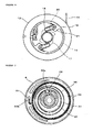
- a starting system for a small-sized engine shown in Fig. 1 includes a recoil starting system A and a motor starting system B stored in a starter case 1.
- the motor starting system B employs a configuration in which a pinion 5 is mounted to an output shaft 3 of a reducer motor 2 by an one-way clutch 4 of a needle bearing, and the pinion 5 is engaged with a starting gear 6 of an engine.
- the starter case 1 includes an inner lid 9 which is secured to a crankcase 7 of the engine together with a screw 8, and the inner lid 9 includes a joint portion 10 with respect to the crankcase 7 and a mounting seat 11 of the reducer motor 2 on the outside thereof.
- the recoil starting system A described above is configured as shown in Fig. 1 in such a manner that a reel 13 is fitted to a spindle 12 provided at the center of the starter case 1, a groove 14 is provided on the periphery of the reel 13 for winding a rope 15, and a recoil spring 16 which is wound up by drawing out of the rope 15 and returns the rope by its restoring force when the rope 15 is released is provided between one side surface of the reel 13 and the starter case 1.
- a plurality of latchets 18 which engage a cam 17 provided on the starting gear 6 are mounted to by a shaft 19 as shown in Fig. 6 , and the latchets 18 are urged by a turn spring 20 against stopper strips 21 provided on one side of each.
- a relay cam 26 whose passive portion 24 is positioned in a spring chamber 25 provided on the starting gear 6 as shown in Fig. 7 is used.
- the relay cam 26 is formed into a cap shape having a disk portion 27 which is positioned between the relay cam 26 and the passive portion 24 as shown in Fig. 4 and Fig. 5 , and is mounted at the center of the bottom portion to an upper surface of the spindle 12 by a headed shaft 28 as shown in Fig. 1 .
- the passive portion 24 positioned in the spring chamber 25 is provided with a segmental groove 29 as shown in Fig.
- a plurality of latchets 32 to be engaged with the relay cam 26 are mounted to the pulley 23 provided on the crankshaft 22 by a shaft 33, as shown in Fig. 8 , and the latchets 32 are urged by a return spring 34 against stoppers 35 provided on one side.
- the motor starting system B is configured in such a manner that the pinion 5 is mounted to the output shaft 3 of the reducer motor 2 by the one-way clutch 4 of the needle bearing and the pinion 5 is engaged with the starting gear 6 as described above, when motor-starting is carried out by rotating the reducer motor 2, the one-way clutch 4 of the needle bearing couples the output shaft 3 and the pinion 5 to transmit the rotation of the reducer motor 2 to the starting gear 6, and then from the starting gear 6 to the relay cam 26, the pulley 23, and the crankshaft 22 to start the engine.
- the one-way clutch 4 of the needle bearing releases the pinion 5 and the output shaft 3, the reducer motor 2 stays stopped even when the starting gear 6 rotates.
- the one-way clutch 4 of the needle bearing is preferably mounted easily and reliably to the pinion 5. Therefore, by configuring the one-way clutch 4 of the needle bearing in such a manner that a plurality of detent projections 36 are formed on the outer periphery thereof as shown in Fig. 3(a) so as to assume a polygonal shape such as hexagon, and a receiving hole 37 provided in the pinion 5 includes a plurality of detent recesses 38 on the inner periphery thereof so as to assume a polygonal shape such as hexagon as shown in the same drawing, or one or more detent recesses 39 are formed on the outer periphery of the one-way clutch 4 of the needle bearing as shown in Fig.
- the receiving hole 37 provided in the pinion 5 includes one or more detent projections 40 on the inner periphery thereof as shown in the same drawing, the transmission of the rotation from the one-way clutch 4 to the pinion 5 is ensured by the engagement between the projections and the recesses even though the fitting between the outer periphery of the one-way clutch 4 and the receiving hole 37 of the pinion 5 is loosened so as to allow easy fitting and pulling out.
- the reducer motor 2 is an integral combination of the motor 2 and a reducer 41 as shown in Fig. 1 and Fig. 2 , and with the employment of such the reducer motor 2, the presence of a reduction gear in the starter case 1 is eliminated, so that downsizing, light-weight, and cost reduction of the system are achieved.
- a spur gear reducer type whose output shaft 3 is deviated from a shaft 2a of the reducer motor 2 or a planetary gear reducer type whose output shaft 3 is aligned with the shaft 2a of the reducer motor 2 as shown in Fig. 2 is employed.
- the planetary gear reducer type which is structurally compact and enables the weight reduction using resin gears is advantageous.
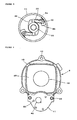
- the starting system is characterized in that the inner lid 9 is provided on the starter case 1.
- the inner lid 9 includes the joint portion 10 with respect to the crankcase 7 and the mounting seat 11 of the reducer motor 2 on one side as shown in Fig. 9 and Fig. 10
- the joint portion 10 includes a mounting hole 43 which is aligned with a mounting hole 42 provided on the periphery of the starter case 1, so that the crankcase 1 and the inner lid 9 can be mounted to the crankcase 7 together by passing a co-securing screw 8 into the mounting hole 42 and the mounting hole 43 and screwing the same into a screw hole 44 provided on the crankcase 7.
- the joint portion 10 of the inner lid 9 with respect to the crankcase 7 includes a recess 45 in which part of the pulley 23 is accommodated as shown in Fig. 10 , and the recess 45 includes a fitting hole 46 formed at the center thereof.
- the disk portion 27 of the relay cam 26 is fitted to the fitting hole 46, the relay cam 26 which is supported only at the bottom portion by the headed shaft 28 is also supported at the periphery thereof by the fitting hole 46, so that the relay cam 26 is stabilized.
- a portion 47 of the recess 45 formed with the fitting hole 46 at the center as descried above located outside the fitting hole 46 corresponds to the spring chamber 25 provided in the starting gear 6 and functions as a lid which closes the spring chamber 25. Therefore, the shock-absorbing recoil spring 30 which engages at the inner end thereof with the segmental groove 29 provided on the passive portion 24 tries to accompany with the passive portion 24 when pulling the relay cam 26 out of the fitting hole 46, the portion 47 restricts it and prevents the shock-absorbing recoil spring 30 from jumping out from the spring chamber 25.
- the mounting seat 11 of the motor is formed into a flat panel having the shape and the surface area which match the reducer 41 of the reducer motor 2, and includes a hole 48 which allows passage of the output shaft 3 of the motor 2 and a hole 50 which allows passage of a mounting screw 49. Therefore, when the output shaft 3 is passed through the hole 48, the reducer motor 2 is placed on the outer surface of the mounting seat 11, and the mounting screw 49 is screwed from the hole 50 to the reducer motor 2, the reducer motor 2 can b mounted to the mounting seat 11 easily.
- the reducer motor 2 mounted to the mounting seat 11 as described above is protected by mounting a protection cover 51 as shown in Fig. 1 and Fig. 2 .
- the protection cover 51 is formed into a shape which accommodates the reducer motor 2, and is adapted to mount the starter case 12 with the intermediary of the inner lid 9 by providing a mounting strip 52 on the periphery of the opening side as shown in Fig. 10 , overlapping the mounting strip 52 on the mounting seat 11 of the motor, passing a screw 54 into a hole 53 and then into a hole 55 provided on the mounting seat 11 as shown in Fig. 9 , and screwing the same into a screw hole, not shown, of the starter case 1.
- the output shaft 3 of the reducer motor 2 rotates and, in this case, the one-way clutch 4 of the needle bearing couples the output shaft 3 and the pinion 5, transmits the rotation of the output shaft 3 to the starting gear 6 by the pinion 5, and rotates the starting gear 6.
- the shock-absorbing recoil spring 30 is present between the starting gear 6 and the passive portion 24 of the relay cam 26, and does not transmit the rotation to the passive portion 24 while it is wound up by the rotation of the starting gear 6, and transmits the rotation to the passive portion 24 when the winding limit is reached to rotates the relay cam 26 and the starting gear 6 together.
- the relay cam 26 functions to cause the engine to start by transmitting the rotation to the pulley 23 by the latchets 32 and rotating the crankshaft 22 and, in this case, the reel 13 is stopped because the latchets 18 are arranged so as to avoid the cam 17 provided on the starting gear 6.
- the starting gear 6 is adapted to start engine by being stopped when the shock-absorbing recoil spring 30 is being wound up, being rotated when it reaches the winding limit, transmitting the rotation from the relay cam 26 to the pulley 23, and rotating the crankshaft 22.
- the pinion 5 is rotated by the starting gear 6, but the one-way clutch 4 of the needle bearing mounted to the output shaft 3 of the reducer motor 2 releases the pinion 5 and the output shaft 3, so that the reducer motor 2 is not rotated.
- the present invention can be used for achieving downsizing, light-weight, and cost reduction of the starting system for a small-sized engine.
Landscapes
- Engineering & Computer Science (AREA)
- Chemical & Material Sciences (AREA)
- Combustion & Propulsion (AREA)
- Mechanical Engineering (AREA)
- General Engineering & Computer Science (AREA)
- Connection Of Motors, Electrical Generators, Mechanical Devices, And The Like (AREA)
Applications Claiming Priority (2)
| Application Number | Priority Date | Filing Date | Title |
|---|---|---|---|
| JP2006186805A JP4846469B2 (ja) | 2006-07-06 | 2006-07-06 | 小型エンジンの始動装置 |
| PCT/JP2007/062248 WO2008004434A1 (fr) | 2006-07-06 | 2007-06-18 | Dispositif de démarrage pour un moteur de petite dimension |
Publications (3)
| Publication Number | Publication Date |
|---|---|
| EP2039926A1 true EP2039926A1 (de) | 2009-03-25 |
| EP2039926A4 EP2039926A4 (de) | 2015-07-08 |
| EP2039926B1 EP2039926B1 (de) | 2019-04-17 |
Family
ID=38894405
Family Applications (1)
| Application Number | Title | Priority Date | Filing Date |
|---|---|---|---|
| EP07767146.9A Active EP2039926B1 (de) | 2006-07-06 | 2007-06-18 | Startvorrichtung für kleinmotor |
Country Status (4)
| Country | Link |
|---|---|
| US (1) | US7739992B2 (de) |
| EP (1) | EP2039926B1 (de) |
| JP (1) | JP4846469B2 (de) |
| WO (1) | WO2008004434A1 (de) |
Cited By (3)
| Publication number | Priority date | Publication date | Assignee | Title |
|---|---|---|---|---|
| EP2500559A1 (de) * | 2011-03-17 | 2012-09-19 | Makita Corporation | Startvorrichtung für eine Verbrennungskraftmaschine, insbesondere Seilzugstartvorrichtung |
| EP3147494A1 (de) * | 2015-09-22 | 2017-03-29 | Coza International Limited Hongkong | Startersystem mit zwei quellen für einen motor |
| EP1950412A4 (de) * | 2005-10-17 | 2017-08-09 | Starting Industrial Co., Ltd. | Starter für kleinen motor |
Families Citing this family (5)
| Publication number | Priority date | Publication date | Assignee | Title |
|---|---|---|---|---|
| EP2463556B1 (de) | 2009-08-04 | 2018-04-25 | JTEKT Corporation | Elektropumpeneinheit |
| US8444648B2 (en) | 2009-09-17 | 2013-05-21 | The Anspach Effort, Inc. | Surgical file |
| US20110126790A1 (en) * | 2009-12-02 | 2011-06-02 | Neil Vacek | Battery Powered Electric Starter |
| CN104295427B (zh) * | 2014-09-25 | 2016-08-24 | 重庆特飞航空动力科技有限公司 | 二冲程水冷发动机用启动机构 |
| DE102014016172A1 (de) * | 2014-11-03 | 2016-05-04 | Audi Ag | Antriebsvorrichtung für ein hybridgetriebenes Kraftfahrzeug |
Family Cites Families (20)
| Publication number | Priority date | Publication date | Assignee | Title |
|---|---|---|---|---|
| US4848288A (en) * | 1987-05-19 | 1989-07-18 | Starting Industry Co., Ltd. | Starting apparatus |
| JP2521096B2 (ja) | 1987-05-19 | 1996-07-31 | スタ−テング工業株式会社 | 始動装置 |
| JPH0649899Y2 (ja) * | 1987-11-25 | 1994-12-14 | 株式会社共立 | 自動始動器付携帯形作業機械用内燃機関 |
| JP2725302B2 (ja) * | 1988-08-30 | 1998-03-11 | 日本電気株式会社 | 導波路型波長変換素子 |
| DE3831710A1 (de) * | 1988-09-17 | 1990-03-22 | Stihl Maschf Andreas | Startvorrichtung fuer einen verbrennungsmotor |
| JP2704643B2 (ja) * | 1988-10-14 | 1998-01-26 | ヤンマーディーゼル株式会社 | エンジンの始動装置 |
| JP2532927B2 (ja) * | 1988-10-22 | 1996-09-11 | スターテング工業株式会社 | 小型エンジンの始動装置 |
| US5083534A (en) * | 1989-04-05 | 1992-01-28 | Mitsubishi Jukogyo Kabushiki Kaisha | Spiral spring type starter apparatus for an internal combustion engine |
| DE4215509C2 (de) * | 1992-05-12 | 1994-11-24 | Fichtel & Sachs Ag | Starteinrichtung für Verbrennungsmotoren |
| US6199529B1 (en) * | 1998-03-31 | 2001-03-13 | Honda Giken Kogyo Kabushiki Kaisha And Starting Industrial Co., Ltd. | Engine starting apparatus |
| CN1143058C (zh) * | 1999-08-06 | 2004-03-24 | 本田技研工业株式会社 | 发动机起动装置 |
| JP4428617B2 (ja) * | 2003-06-13 | 2010-03-10 | 本田技研工業株式会社 | トルク設定アダプタ |
| JP4619215B2 (ja) * | 2004-08-09 | 2011-01-26 | ハスクバーナ・ゼノア株式会社 | エンジン始動装置 |
| US20060027201A1 (en) * | 2004-08-09 | 2006-02-09 | Ryou Ono | Engine starter |
| WO2006043579A1 (ja) * | 2004-10-20 | 2006-04-27 | Mitsuba Corporation | アイドルギヤ付始動電動機 |
| CN101044314A (zh) * | 2004-10-20 | 2007-09-26 | 株式会社美姿把 | 带惰轮的起动电动机 |
| JP2006322354A (ja) * | 2005-05-18 | 2006-11-30 | Mitsubishi Heavy Ind Ltd | 小型内燃エンジンの始動方法及び渦巻ばね式スタータ装置 |
| US7331321B2 (en) * | 2005-07-01 | 2008-02-19 | Gene Thompson | Handheld electric starter for engines and method of use |
| DE112006002520B4 (de) * | 2005-09-21 | 2018-01-04 | Mitsuba Corp. | Anlasser |
| JP4684255B2 (ja) * | 2007-03-22 | 2011-05-18 | 株式会社ミツバ | スタータ |
-
2006
- 2006-07-06 JP JP2006186805A patent/JP4846469B2/ja active Active
-
2007
- 2007-06-18 WO PCT/JP2007/062248 patent/WO2008004434A1/ja active Application Filing
- 2007-06-18 EP EP07767146.9A patent/EP2039926B1/de active Active
- 2007-06-18 US US12/309,041 patent/US7739992B2/en active Active
Non-Patent Citations (1)
| Title |
|---|
| See references of WO2008004434A1 * |
Cited By (6)
| Publication number | Priority date | Publication date | Assignee | Title |
|---|---|---|---|---|
| EP1950412A4 (de) * | 2005-10-17 | 2017-08-09 | Starting Industrial Co., Ltd. | Starter für kleinen motor |
| EP2500559A1 (de) * | 2011-03-17 | 2012-09-19 | Makita Corporation | Startvorrichtung für eine Verbrennungskraftmaschine, insbesondere Seilzugstartvorrichtung |
| CN102678418A (zh) * | 2011-03-17 | 2012-09-19 | 株式会社牧田 | 用于至少一个内燃机的起动装置、特别是拉缆式起动装置 |
| CN102678418B (zh) * | 2011-03-17 | 2015-10-14 | 株式会社牧田 | 用于至少一个内燃机的起动装置、特别是拉缆式起动装置 |
| US9163599B2 (en) | 2011-03-17 | 2015-10-20 | Makita Corporation | Starting device for at least one combustion engine, in particular cable pull starting device |
| EP3147494A1 (de) * | 2015-09-22 | 2017-03-29 | Coza International Limited Hongkong | Startersystem mit zwei quellen für einen motor |
Also Published As
| Publication number | Publication date |
|---|---|
| EP2039926A4 (de) | 2015-07-08 |
| WO2008004434A1 (fr) | 2008-01-10 |
| US7739992B2 (en) | 2010-06-22 |
| US20090114181A1 (en) | 2009-05-07 |
| JP2008014242A (ja) | 2008-01-24 |
| JP4846469B2 (ja) | 2011-12-28 |
| EP2039926B1 (de) | 2019-04-17 |
Similar Documents
| Publication | Publication Date | Title |
|---|---|---|
| EP2039926B1 (de) | Startvorrichtung für kleinmotor | |
| EP1384881B1 (de) | Seilstartvorrichtung | |
| EP1558845B1 (de) | Seilstartvorrichtung mit dämpfer/puffer-feder | |
| EP0321960B1 (de) | Sicherheitsgurt mit Spannvorrichtung | |
| JP6135117B2 (ja) | 車両用駆動装置 | |
| CN1388866A (zh) | 内燃机起动和停止装置 | |
| JP2009108909A (ja) | チェーン伝動用テンショナレバー | |
| EP1865196B1 (de) | Kraftübertragungsmechanismus zwischen anlasser und motor | |
| JPWO2006043579A1 (ja) | アイドルギヤ付始動電動機 | |
| EP1647706B1 (de) | Seilstartvorrichtung | |
| EP0458593A1 (de) | Anlassvorrichtung für Verbrennungsmotor | |
| US6622683B2 (en) | Engine starting and stopping device | |
| EP1894456A1 (de) | Kupplungshebelvorrichtung | |
| US20040168668A1 (en) | Recoil starter of force accumulation type | |
| CN111608518B (zh) | 用于以致动器方式打开盖的致动装置 | |
| US20090032787A1 (en) | Hoisting and pulling device | |
| EP1965073B1 (de) | Motorstartvorrichtung | |
| EP3550099B1 (de) | Antriebsanordnung für ein hebelartiges türschloss | |
| JP5625762B2 (ja) | 車両用ドア駆動装置 | |
| CA2347317C (en) | Engine starter | |
| WO2020153379A1 (ja) | リコイルスタータ用のロープリールおよびリコイルスタータ | |
| JP2004060446A (ja) | リコイルスタータ | |
| CN113973788A (zh) | 钓鱼用电动渔线轮 | |
| JP6487857B2 (ja) | 電動ステアリングロック装置 | |
| JP6577371B2 (ja) | 電動ステアリングロック装置 |
Legal Events
| Date | Code | Title | Description |
|---|---|---|---|
| PUAI | Public reference made under article 153(3) epc to a published international application that has entered the european phase |
Free format text: ORIGINAL CODE: 0009012 |
|
| 17P | Request for examination filed |
Effective date: 20090119 |
|
| AK | Designated contracting states |
Kind code of ref document: A1 Designated state(s): AT BE BG CH CY CZ DE DK EE ES FI FR GB GR HU IE IS IT LI LT LU LV MC MT NL PL PT RO SE SI SK TR |
|
| AX | Request for extension of the european patent |
Extension state: AL BA HR MK RS |
|
| RBV | Designated contracting states (corrected) |
Designated state(s): DE IT SE |
|
| DAX | Request for extension of the european patent (deleted) | ||
| RA4 | Supplementary search report drawn up and despatched (corrected) |
Effective date: 20150609 |
|
| RIC1 | Information provided on ipc code assigned before grant |
Ipc: F02N 3/02 20060101ALI20150602BHEP Ipc: F02N 15/00 20060101ALI20150602BHEP Ipc: F02N 15/02 20060101ALI20150602BHEP Ipc: F02N 11/00 20060101AFI20150602BHEP |
|
| STAA | Information on the status of an ep patent application or granted ep patent |
Free format text: STATUS: EXAMINATION IS IN PROGRESS |
|
| 17Q | First examination report despatched |
Effective date: 20171222 |
|
| GRAP | Despatch of communication of intention to grant a patent |
Free format text: ORIGINAL CODE: EPIDOSNIGR1 |
|
| STAA | Information on the status of an ep patent application or granted ep patent |
Free format text: STATUS: GRANT OF PATENT IS INTENDED |
|
| INTG | Intention to grant announced |
Effective date: 20181102 |
|
| GRAS | Grant fee paid |
Free format text: ORIGINAL CODE: EPIDOSNIGR3 |
|
| GRAA | (expected) grant |
Free format text: ORIGINAL CODE: 0009210 |
|
| STAA | Information on the status of an ep patent application or granted ep patent |
Free format text: STATUS: THE PATENT HAS BEEN GRANTED |
|
| AK | Designated contracting states |
Kind code of ref document: B1 Designated state(s): DE IT SE |
|
| REG | Reference to a national code |
Ref country code: DE Ref legal event code: R096 Ref document number: 602007058130 Country of ref document: DE |
|
| REG | Reference to a national code |
Ref country code: SE Ref legal event code: TRGR |
|
| REG | Reference to a national code |
Ref country code: DE Ref legal event code: R097 Ref document number: 602007058130 Country of ref document: DE |
|
| PLBE | No opposition filed within time limit |
Free format text: ORIGINAL CODE: 0009261 |
|
| STAA | Information on the status of an ep patent application or granted ep patent |
Free format text: STATUS: NO OPPOSITION FILED WITHIN TIME LIMIT |
|
| 26N | No opposition filed |
Effective date: 20200120 |
|
| PGFP | Annual fee paid to national office [announced via postgrant information from national office to epo] |
Ref country code: DE Payment date: 20230627 Year of fee payment: 17 |
|
| PGFP | Annual fee paid to national office [announced via postgrant information from national office to epo] |
Ref country code: IT Payment date: 20230627 Year of fee payment: 17 |
|
| PGFP | Annual fee paid to national office [announced via postgrant information from national office to epo] |
Ref country code: SE Payment date: 20230630 Year of fee payment: 17 |