WO2020153379A1 - リコイルスタータ用のロープリールおよびリコイルスタータ - Google Patents
リコイルスタータ用のロープリールおよびリコイルスタータ Download PDFInfo
- Publication number
- WO2020153379A1 WO2020153379A1 PCT/JP2020/001995 JP2020001995W WO2020153379A1 WO 2020153379 A1 WO2020153379 A1 WO 2020153379A1 JP 2020001995 W JP2020001995 W JP 2020001995W WO 2020153379 A1 WO2020153379 A1 WO 2020153379A1
- Authority
- WO
- WIPO (PCT)
- Prior art keywords
- rope
- reel
- rope reel
- arch portion
- hole
- Prior art date
Links
Images


Classifications
-
- F—MECHANICAL ENGINEERING; LIGHTING; HEATING; WEAPONS; BLASTING
- F02—COMBUSTION ENGINES; HOT-GAS OR COMBUSTION-PRODUCT ENGINE PLANTS
- F02N—STARTING OF COMBUSTION ENGINES; STARTING AIDS FOR SUCH ENGINES, NOT OTHERWISE PROVIDED FOR
- F02N3/00—Other muscle-operated starting apparatus
- F02N3/02—Other muscle-operated starting apparatus having pull-cords
-
- F—MECHANICAL ENGINEERING; LIGHTING; HEATING; WEAPONS; BLASTING
- F02—COMBUSTION ENGINES; HOT-GAS OR COMBUSTION-PRODUCT ENGINE PLANTS
- F02N—STARTING OF COMBUSTION ENGINES; STARTING AIDS FOR SUCH ENGINES, NOT OTHERWISE PROVIDED FOR
- F02N15/00—Other power-operated starting apparatus; Component parts, details, or accessories, not provided for in, or of interest apart from groups F02N5/00 - F02N13/00
- F02N15/006—Assembling or mounting of starting devices
-
- F—MECHANICAL ENGINEERING; LIGHTING; HEATING; WEAPONS; BLASTING
- F02—COMBUSTION ENGINES; HOT-GAS OR COMBUSTION-PRODUCT ENGINE PLANTS
- F02N—STARTING OF COMBUSTION ENGINES; STARTING AIDS FOR SUCH ENGINES, NOT OTHERWISE PROVIDED FOR
- F02N5/00—Starting apparatus having mechanical power storage
- F02N5/02—Starting apparatus having mechanical power storage of spring type
Definitions
- the present disclosure relates to a recoil starter that can apply a starting torque to an engine by pulling a rope.
- a starting device for starting an engine As a starting device for starting an engine, a rope wound around a rope reel is pulled to rotate the rope reel, and the rotation of the rope reel is transmitted to a rotating member coupled to a crankshaft of the engine.
- a recoil starter is known in which a crankshaft of an engine is rotated to start the engine.
- the end of the rope wound around the rope reel is pulled out of the case so that one of the ends of the rope can be pulled and the other end is attached to the rope reel.
- the rope end attached to the rope reel is locked to the side surface of the rope reel by forming a knot.
- the rope knot is fixed not to the starter case side that covers the rope reel but to the side surface of the rope reel on the engine side.
- the present disclosure provides a rope reel for a recoil starter in which the tip of the rope does not interfere with the rotating member on the engine side and the rope can be easily replaced.
- the present disclosure also relates to the end of the rope wound on the rope reel of the recoil starter.
- a rope reel provided in a recoil starter includes a rope holding groove configured to wind a rope, flange portions arranged on both sides of the rope holding groove, and the rope holding groove. It is configured to penetrate the end of the wound rope, and includes a through hole provided in the flange portion, and an arch portion provided on a side surface of the rope reel adjacent to the through hole. The arch portion is configured to insert the rope, and the arch portion can hold the inserted rope along a side surface of the rope reel.
- the rope reel for the recoil starter has a through hole provided in the flange portion for penetrating the end of the rope wound around the rope holding groove, and a rope reel adjacent to the through hole.
- An arch portion provided on a side surface of the rope reel is inserted into the arch portion, and the inserted rope can be held along the side surface of the rope reel.
- the tip end of the rope can be firmly fixed by inserting it into the arch portion, so that the tip end of the rope does not interfere with the rotating member on the engine side.
- the rope reel can be arranged close to the rotating member, and the degree of freedom of layout can be increased.
- the recoil starter can be downsized by reducing the width of the recoil starter.
- the rope can be removed simply by pulling it out from the arch portion, so that the rope can be easily replaced.
- FIG. 1 is a cross-sectional view showing a recoil starter in a state in which a rope end is not held.
- FIG. 2A is a side view showing a rope reel to which a rope is attached.
- FIG. 2B is a front view showing the rope reel.
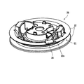
- FIG. 3 is a perspective view showing a rope reel to which a rope is attached.
- FIG. 4 is a perspective view showing a rope reel.
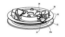
- FIG. 5 is a perspective view of the rope reel viewed from another angle.
- FIG. 6 is a perspective view showing a rope reel according to the first modification.
- FIG. 7A is a perspective view showing a rope reel according to the second modification.
- FIG. 7B is a partially enlarged perspective view showing the rope reel according to the second modification.
- the recoil starter 10 starts the engine by applying a rotational force to the engine crankshaft 42.
- the recoil starter 10 includes a starter case 11, a rope reel 20, a ratchet member 40, a drive pulley 41, and the like.
- the starter case 11 accommodates the main components of the recoil starter 10 and is arranged so as to cover the side surface of the engine. At the center of the starter case 11, there is provided a reel support shaft 11a that protrudes inward so as to face the engine crankshaft 42. A rope reel 20, which will be described later, is rotatably attached to the reel support shaft 11a.
- the rope reel 20 is a wheel-shaped member, and includes a rope holding groove 21 configured to wind the rope 30 around the rope reel 20.
- the rope reel 20 is rotatably attached to the reel support shaft 11a by penetrating the reel support shaft 11a through a hole formed in the center thereof.
- One end of the rope 30 wound around the rope reel 20 is fixed to the rope reel 20, and the other end is pulled out of the starter case 11. Therefore, when the operator pulls the pulled-out rope 30 vigorously, the rope reel 20 is configured to rotate around the reel support shaft 11a.
- the return spring is a spring and has one end fixed to the starter case 11 and the other end fixed to the rope reel 20.
- rotational force is accumulated in the return spring.
- the rope reel 20 is reversely rotated by the spring force accumulated in the return spring, and the rope reel 20 winds the rope 30.
- the ratchet member 40 is attached to the rope reel 20 so as to rotate integrally with the rope reel 20.
- the ratchet member 40 is swingably attached to the side surface of the rope reel 20, and the ratchet member 40 is swingably attached to the ratchet member 40 so that the ratchet member 40 is engaged with an inner peripheral surface of a drive pulley 41 described later. Has been formed. Since the structure of the related art may be applied to the ratchet member 40, the structure of the ratchet member 40 will not be described in detail, but the rope reel 20 is in a predetermined direction with respect to the drive pulley 41 (direction in which the engine is started). The drive pulley 41 is engaged only when the drive pulley 41 is rotated.
- the ratchet member 40 swings to engage the ratchet member 40 with the drive pulley 41, and the rotational force of the rope reel 20 is driven. It is transmitted to the pulley 41.
- the ratchet member 40 swings in the retracting direction and does not engage with the drive pulley 41. As a result, the rope reel 20 and the drive pulley 41 do not transmit rotational force to each other.
- the drive pulley 41 is a tubular member and is connected to the engine crankshaft 42.
- the drive pulley 41 is rotatably supported coaxially with the rotation shaft of the rope reel 20 (reel support shaft 11a).
- the engine crankshaft 42 integrally connected to the drive pulley 41 rotates, and a starting rotational force is applied to the engine.
- a rotating member 43 that rotates integrally with the engine crankshaft 42 is attached to the engine crankshaft 42 according to the present embodiment.
- a rotating member 43 having a fan shape for blowing air to the engine is attached.
- the end of the rope 30 attached to the rope reel 20 is locked to the side surface of the rope reel 20 by forming a knot 30b. Further, the knot 30b of the rope 30 is fixed to the side surface of the rope reel 20 arranged on the engine side as shown in FIG. With the above configuration, it is not necessary to provide a gap for holding the knot 30b of the rope 30 between the starter case 11 that covers the rope reel 20 and the rope reel 20, so that the starter case 11 and the rope reel 20 can be formed as much as possible. It can be placed close to each other. Thereby, the width of the recoil starter 10 can be made as small as possible.
- the rope reel 20 is capable of holding the end of the rope 30, and is formed so as to prevent interference between the rotating member 43 and the tip portion 30a of the rope 30.
- the flange portions 22 are formed in a pair so as to face each other, and the rope holding groove 21 is formed between the pair of flange portions 22. As shown in FIGS. 4 and 5, the flange portion 22 arranged on the engine side of the pair of flange portions 22 has a penetrating structure configured to penetrate the end of the rope 30 wound around the rope holding groove 21. The hole 22a is formed.
- the terminal accommodating portion 23 is configured to accommodate the knot 30b of the rope 30 and is formed by a wall 23a that surrounds the through hole 22a.
- the terminal housing portion 23 is surrounded by a wall 23 a provided so as to project from one side of the rope reel 20 in the axial direction of the rope reel 20. Further, since the tip portion of the wall 23a is not covered, the knot 30b of the rope 30 is exposed on the side surface of the rope reel 20 as shown in FIG. 2A.
- a through hole 23b is formed in the wall 23a of the terminal accommodating portion 23.
- the insertion hole 23b is formed in at least one of the walls 23a forming the terminal accommodating portion 23.
- the insertion hole 23b is formed in the wall 23a arranged in the circumferential direction when viewed from the through hole 22a.
- the insertion hole 23b connects the terminal accommodating portion 23 and the arch portion 24.
- the insertion hole 23b is configured such that the rope 30 is guided to the arch portion 24 by inserting the rope 30 from the terminal accommodation portion 23 into the insertion hole 23b.
- the arch portion 24 is configured to hold the tip side of the rope 30 with respect to the knot 30b.
- the arch portion 24 is formed with an annular insertion passage through which the rope 30 can be inserted, and the rope 30 through which the arch portion 24 is inserted can be held along the side surface of the rope reel 20.
- the arch portion 24 according to the present embodiment is formed continuously with the insertion hole 23b formed in the wall 23a of the terminal accommodating portion 23. In other words, the terminal accommodating portion 23 is provided on one side and the arch portion 24 is provided on the other side, with the wall 23a having the insertion hole 23b formed therebetween.
- the arch portion 24 is arranged adjacent to the terminal accommodating portion 23 along the circumferential direction of the flange portion 22. Therefore, the end of the rope 30 held by the arch portion 24 is also held along the circumferential direction of the flange portion 22 as shown in FIG. 2A.
- the arch portion 24 includes a pair of side walls 24c standing upright on the side surface of the rope reel 20 and an upper wall 24a connecting the upper ends of the pair of side walls 24c. .. More specifically, the pair of side walls 24c and the upper wall 24a form a substantially U-shaped arch portion 24.
- the width of the arch portion 24 (the width of the pair of side walls 24c and the width between the side surface of the rope reel 20 and the upper wall 24a) is set so that the tip portion 30a of the rope 30 can be easily inserted. It is designed to be slightly larger than the diameter.
- the upper wall 24a is provided with a cutout 24b at the end farther from the through hole 22a (or the terminal accommodating portion 23) (in other words, the upper wall 24a).
- a cutout 24b formed on the side where the rope 30 is led out from the arch portion 24).
- the side wall 24c is formed with an opening 24d for exposing the rope 30, as shown in FIG. 3, for example.
- the opening 24d By providing the opening 24d, the rope 30 can be operated from the opening 24d when the tip portion 30a of the rope 30 is passed through the arch portion 24, and the rope 30 can be easily passed.
- a scale 25 is provided on the side surface of the rope reel 20 for confirming the position of the tip portion 30a of the rope 30 penetrating the arch portion 24.
- the scale 25 is formed along the circumferential direction of the flange portion 22 on an extension line of the arch portion 24 (at a position apart from the arch portion 24) with a predetermined distance from the arch portion 24.
- the scale 25 is displayed on the side surface of the rope reel 20 by a method of a related art such as marking, molding, or printing.
- the arch portion 24 is provided on the side surface of the rope 20. The arch portion 24 can insert the rope 30 therein, and can hold the inserted rope 30 along the side surface of the rope reel 20. Therefore, since the tip end portion 30a of the rope 30 can be firmly fixed by inserting it into the arch portion 24, the tip end portion 30a of the rope 30 does not interfere with the rotating member 43 on the engine side.
- the rope reel 20 can be arranged close to the rotating member 43, and the degree of freedom of layout can be increased.
- the width of the recoil starter 10 can be reduced to reduce the size of the recoil starter 10.
- the rope 30 can be removed only by pulling it out from the arch portion 24, the rope 30 can be easily replaced.
- the wall 23a so as to surround the through hole 22a, the terminal accommodating portion 23 that accommodates the knot 30b of the rope 30 is formed, and the arch portion 24 is formed on the wall 23a of the terminal accommodating portion 23. It is formed continuously with the insertion hole 23b.
- the knot 30b of the rope 30 may be formed on the basis of the height of the wall 23a of the terminal accommodating portion 23, it is easy to attach the rope 30.
- the rope 30 is held by the arch portion 24 only by inserting the terminal on the tip side of the knot 30b of the rope 30 into the insertion hole 23b formed in the wall 23a of the terminal housing portion 23. It is possible not to interfere with the rotating member 43 on the side.
- an opening 24d exposing the rope 30 is formed on the side surface of the arch portion 24. Therefore, since the rope 30 can be operated from the opening 24d when the rope 30 is inserted or removed, the work of attaching or detaching the rope 30 can be easily performed.
- the rope reel 20 there is provided a scale 25 for confirming the position of the tip portion 30a of the rope 30 which penetrates the arch portion 24.
- the scale 25 since the length of the end of the rope 30 can be controlled by the scale 25, the rope 30 can be attached so as not to interfere with the engine-side rotating member 43.
- the arch portion 24 is formed integrally with the rope reel 20 and is not a separate component, it is possible to avoid an increase in cost due to the provision of the separate component.
- the shape of the arch portion 24 is not limited to the shape described in the above embodiment, and various shapes can be considered.
- a semi-cylindrical arch portion 24 may be formed.
- the terminal accommodating portion 23 is omitted, but the terminal accommodating portion 23 may be omitted to have a simple shape.
- the arch portion 24 may be formed by a holding member 27 that is attachable to and detachable from the side surface of the rope reel 20.
- a holding member 27 that is attachable to and detachable from the side surface of the rope reel 20.
- a locking claw 27a having a return shape may be provided at the tip of the pressing member 27, and a mounting hole 28 that can be engaged with the locking claw 27a may be provided on the side surface of the rope reel 20.
- the retaining member 27 can be attached to the side surface of the rope reel 20 by engaging the locking claw 27a with the attachment hole 28, and the arch closed in a ring shape on the side surface of the rope reel 20 by attaching the retaining member 27.
- the part 24 may be formed.
- the arch portion 24 is formed by the detachable pressing member 27 as described above, the end of the rope 30 can be pressed from the rear, so that the assembling property is improved. Further, in such a configuration, since it is not necessary to consider the ease of passing the rope 30 through the arch portion 24, it is not necessary to make the width of the arch portion 24 larger than the diameter of the rope 30. Therefore, the width of the arch portion 24 can be set so as to hold down the rope 30 and the holding force of the rope 30 can be increased.
Landscapes
- Engineering & Computer Science (AREA)
- Chemical & Material Sciences (AREA)
- Combustion & Propulsion (AREA)
- Mechanical Engineering (AREA)
- General Engineering & Computer Science (AREA)
- Storing, Repeated Paying-Out, And Re-Storing Of Elongated Articles (AREA)
- Storage Of Web-Like Or Filamentary Materials (AREA)
Abstract
リコイルスタータに設けられるロープリールは、ロープ保持溝と、前記ロープ保持溝の両側に配置されたフランジ部と、前記ロープ保持溝に巻き付けたロープの端末を貫通させるように構成されて前記フランジ部に設けられた貫通穴と、前記貫通穴に隣接して前記ロープリールの側面に設けられたアーチ部と、備える。前記アーチ部は、前記ロープを挿通するように構成され、該アーチ部が当該挿通されたロープを前記ロープリールの側面に沿って保持可能である。上記の構成によれば、ロープの先端部がエンジン側の回転部材に干渉することから防止される。
Description
本開示は、ロープを引き操作することでエンジンに始動回転力を付与することができるリコイルスタータに関する。
エンジンを始動させる始動装置として、ロープリールに巻き回されたロープを牽引することによりロープリールを回転させ、該ロープリールの回転をエンジンのクランク軸に結合された回転部材に伝達し、該回転部材を介してエンジンのクランク軸を回転してエンジンを始動させるリコイルスタータが知られている。
ロープリールに巻き回されるロープの端末は、当該ロープの端末のうち一方が引き操作可能となるようにケースの外部に引き出されており、他方がロープリールに取り付けられている。例えば、日本国特開2012-251561号公報に記載される構成においては、ロープリールに取り付けられるロープの端末は、結び目を作ることでロープリールの側面に対して係止されている。当該ロープの結び目は、ロープリールを覆うスタータケース側ではなく、エンジン側のロープリールの側面に固定されている。上記の構成により、ロープリールを覆うスタータケースとロープリールとの間にロープの結び目を保持するための隙間を設ける必要がないので、スタータケースとロープリールとができる限り互いに接近するように配置することができる。これにより、リコイルスタータの幅ができるだけ小さくなり、リコイルスタータをコンパクトにすることができる。
しかし、上記の日本国特開2012-251561号公報に記載される構成では、ロープの結び目よりも先端側の部分が固定されていないため、エンジン側の回転部材にロープの先端部が干渉するおそれがあった。
上記の干渉を防止する方法としては、ロープの先端部を結び目付近で挟み込む方法が考えられる。しかしながら、ロープの先端部を挟み込む方法では、ロープが緩むといった原因に起因し、結び目付近で挟み込まれた先端部が外れてしまうおそれがあった。
上記の干渉を防止する別の方法として、接着剤等の手段でロープの先端部を固定する方法が考えられる。しかしながら、接着剤等の手段でロープの先端部を固定してしまうと、ロープを交換することができなくなるという問題があった。
本開示は、ロープの先端部がエンジン側の回転部材に干渉することがない、かつ、ロープが容易に交換されるリコイルスタータ用のロープリールを提供する。また、本開示は、リコイルスタータのロープリールに巻き付けたロープの端末に関連する。
本発明の一態様によれば、リコイルスタータに設けられるロープリールは、ロープを巻き付けるように構成されたロープ保持溝と、前記ロープ保持溝の両側に配置されたフランジ部と、前記ロープ保持溝に巻き付けた前記ロープの端末を貫通させるように構成され、前記フランジ部に設けられた貫通穴と、前記貫通穴に隣接して、前記ロープリールの側面に設けられたアーチ部と、を備える。前記アーチ部は、前記ロープを挿通するように構成され、該アーチ部が当該挿通されたロープを前記ロープリールの側面に沿って保持可能である。
本発明の前記態様によれば、リコイルスタータ用のロープリールは、ロープ保持溝に巻き付けたロープの端末を貫通させるためにフランジ部に設けられた貫通穴と、貫通穴に隣接してロープリールの側面に設けられたアーチ部と、を備え、アーチ部は、ロープを挿通可能であり、挿通したロープをロープリールの側面に沿って保持可能である。上述の構成によれば、アーチ部に挿通することでロープの先端部をしっかりと固定することができるので、ロープの先端部がエンジン側の回転部材に干渉することがない。また、ロープの先端部がロープリールの側面に沿って保持されるため、ロープリールを回転部材に接近して配置することが可能となり、レイアウトの自由度を増すことができる。例えば、リコイルスタータの幅を小さくして、リコイルスタータを小型化することができる。また、アーチ部から引き抜くだけでロープを外すことができるので、ロープの交換も容易に行うことができる。
本発明の実施形態が、図を参照しながら説明される。
本実施形態に係るリコイルスタータ10は、エンジンクランク軸42に回転力を付与することにより、エンジンを始動させる。図1に示されるように、リコイルスタータ10は、スタータケース11、ロープリール20、ラチェット部材40、駆動プーリ41などを備えて構成されている。
本実施形態に係るリコイルスタータ10は、エンジンクランク軸42に回転力を付与することにより、エンジンを始動させる。図1に示されるように、リコイルスタータ10は、スタータケース11、ロープリール20、ラチェット部材40、駆動プーリ41などを備えて構成されている。
スタータケース11は、リコイルスタータ10の主要構成部品を収容しつつ、エンジンの側面部を覆うように配置されている。スタータケース11の中央には、エンジンクランク軸42と対向するように内側に突出したリール支軸11aが設けられている。このリール支軸11aには、後述されるロープリール20が回転可能に取り付けられている。
ロープリール20は、ホイール状の部材であり、そのロープリール20の周囲にロープ30を巻き付けるように構成されるロープ保持溝21を含む。このロープリール20は、その中心部に形成された孔に上記のリール支軸11aを貫通させることで、リール支軸11aに対して回転自在に取り付けられている。このロープリール20に巻回されたロープ30は、そのロープ30のうち一端がロープリール20に固定され、他端がスタータケース11の外部に引き出されている。このため、この引き出されたロープ30を作業者が勢いよく牽引することで、ロープリール20がリール支軸11aを中心に回転するように構成される。
作業者が引き出したロープ30を放すと、ロープリール20はリターンゼンマイによって逆回転し、自動的にロープ30が巻き取られる。リターンゼンマイは、ゼンマイバネであり、リターンゼンマイの一端がスタータケース11に固定され、他端がロープリール20に固定される。ロープ30を引き出すことでロープリール20が回転すると、リターンゼンマイに回転力が蓄積される。また、引かれたロープ30が放されると、リターンゼンマイに蓄積されたバネ力でロープリール20が逆回転し、ロープリール20がロープ30を巻き取るように構成されている。
ラチェット部材40は、ロープリール20と一体的に回転するようにロープリール20に取り付けられている。このラチェット部材40は、ロープリール20の側面に揺動可能に取り付けられており、ラチェット部材40を揺動させることで後述される駆動プーリ41の内周面に係合するようにラチェット部材40が形成されている。このラチェット部材40には関連技術の構造が応用されてもよいため、ラチェット部材40の構成が詳しくは説明されないが、ロープリール20が駆動プーリ41に対して所定の方向(エンジンを始動させる方向)に回転しようとしたときにのみ、駆動プーリ41と係合するように構成される。
すなわち、ロープ30が引き出される操作を行うことで、ロープリール20が回転したとき、ラチェット部材40が揺動することでラチェット部材40が駆動プーリ41に係合し、ロープリール20の回転力が駆動プーリ41に伝達される。一方、ロープリール20がロープ30を巻き取る方向に回転しているとき又は、ロープリール20が回転していないとき、ラチェット部材40は退避方向に揺動して駆動プーリ41に係合しない。その結果、ロープリール20と駆動プーリ41とが互いに回転力を伝達しない。
駆動プーリ41は、筒状の部材であり、エンジンクランク軸42に接続される。この駆動プーリ41は、ロープリール20の回転軸(リール支軸11a)と同軸上において、回転自在に支持されている。この駆動プーリ41にロープリール20の回転力が伝達され、駆動プーリ41が回転を開始すると、駆動プーリ41に一体的に結合されたエンジンクランク軸42が回転し、エンジンに始動回転力が付与される。
本実施形態に係るエンジンクランク軸42には、駆動プーリ41のほかにも、エンジンクランク軸42と一体的に回転する回転部材43が取り付けられている。例えば、エンジンに送風するためのファン形状を備えた回転部材43が取り付けられている。
上述のリコイルスタータ10において、ロープリール20に取り付けられるロープ30の端末は、結び目30bを作ることでロープリール20の側面に対して係止される。また、ロープ30の結び目30bは、図1に示されるようにエンジン側に配置されるロープリール20の側面に固定される。上記の構成により、ロープリール20を覆うスタータケース11とロープリール20との間にロープ30の結び目30bを保持するための隙間を設ける必要がないので、スタータケース11とロープリール20とができる限り互いに接近するように配置することができる。これにより、リコイルスタータ10の幅をできるだけ小さくすることができる。
しかしながら、図1に示すように、ロープ30の結び目30bよりも先端側の部分が固定されていないと、エンジン側の回転部材43にロープ30の先端部30aが干渉するおそれがある。この点に関して、本実施形態に係るロープリール20は、ロープ30の端末を保持可能となっており、回転部材43とロープ30の先端部30aとの干渉を防止できるように形成されている。
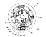
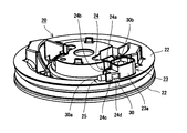
すなわち、本実施形態に係るロープリール20は、図2A及び図2Bに示すように、ロープ保持溝21の両側に配置されたフランジ部22と、ロープリール20の側面に設けられた端末収容部23と、端末収容部23に隣接してロープリール20の側面に設けられたアーチ部24と、を備えている。
フランジ部22は、互いに対向するように一対で形成されており、この一対のフランジ部22の間にロープ保持溝21が形成されている。一対のフランジ部22のうち、エンジン側に配置されるフランジ部22には、図4および図5に示すように、ロープ保持溝21に巻き付けたロープ30の端末を貫通させるように構成された貫通穴22aが形成されている。
端末収容部23は、ロープ30の結び目30bを収容するように構成され、上記の貫通穴22aの周囲を囲む壁23aによって形成されている。端末収容部23は、ロープリール20の軸方向に該ロープリール20の一側から突出するように設けられた壁23aによって囲まれている。また、壁23aの先端部は覆われていないので、図2Aに示すように、ロープ30の結び目30bはロープリール20の側面にて露出する。
この端末収容部23の壁23aには、図5に示すように、挿通穴23bが形成されている。挿通穴23bは、端末収容部23を形成する壁23aのうち少なくとも一つに形成される。本実施形態では、貫通穴22aから見たとき挿通穴23bが周方向に配置された壁23aに形成されている。この挿通穴23bは、端末収容部23とアーチ部24とを連通させる。換言すれば、挿通穴23bは、端末収容部23からロープ30を挿通穴23bに挿入することで、ロープ30がアーチ部24に導かれるように構成される。
アーチ部24は、ロープ30の結び目30bよりも先端側を保持するように構成される。このアーチ部24には、ロープ30を挿通可能な環状の挿通路が形成されており、該アーチ部24が挿通されたロープ30をロープリール20の側面に沿って保持可能である。本実施形態に係るアーチ部24は、端末収容部23の壁23aに形成された挿通穴23bに連続して形成されている。換言すれば、挿通穴23bが形成された壁23aを隔てて、一方側に端末収容部23が設けられ、他方側にアーチ部24が設けられている。
アーチ部24は、フランジ部22の周方向に沿って、端末収容部23に隣接して配置されている。このため、アーチ部24に保持されたロープ30の端末も、図2Aに示すように、フランジ部22の周方向に沿って保持される。
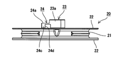
本実施形態に係るアーチ部24は、ロープリール20の側面に対して垂直に立設された一対の側壁24cと、この一対の側壁24cの上端部を接続する上壁24aと、を備えている。より具体的には、一対の側壁24cと上壁24aとによって、略U形状のアーチ部24が形成されている。このアーチ部24の幅(一対の側壁24cの幅、および、ロープリール20の側面と上壁24aとの間の幅)は、ロープ30の先端部30aを挿入しやすくするために、ロープ30の径よりやや大きくなるように設計されている。
なお、上壁24aには、例えば図4に示すように、貫通穴22a(又は、端末収容部23)から遠い側の端部に切り欠き24bが形成されている(換言すれば、上壁24aには、ロープ30がアーチ部24から導出される側に切り欠き24bが形成されている)。この切り欠き24bを設けることで、アーチ部24にロープ30の先端部30aを通すときに、切り欠き24bから先端部30aを引き出しやすくなっている。
また、側壁24cには、例えば図3に示すように、ロープ30を露出させる開口24dが形成されている。この開口24dを設けることで、アーチ部24にロープ30の先端部30aを通すときに、開口24dからロープ30を操作でき、ロープ30を通しやすくなっている。
本実施形態においては、ロープリール20の側面に、アーチ部24を貫通したロープ30の先端部30aの位置が確認される目盛25が設けられている。この目盛25は、フランジ部22の周方向に沿って、アーチ部24の延長線上に(アーチ部24から離れた位置に)、アーチ部24から所定の間隔をあけて形成されている。目盛25は、ロープリール20の側面に、刻印、成形、印刷などの関連技術の方法によって表示されている。ロープリール20にロープ30を取り付けるとき、例えば図2Aに示すように、ロープ30の先端部30aがこの目盛25を超えない長さとなるように結び目30bの位置を調節する。このようにロープ30を取り付けることで、アーチ部24に保持されていないロープ30の先端部30aが長くなりすぎることを防止できるので、ロープ30の先端部30aがエンジン側の部材に干渉することを防止できる。
以上説明したように、本実施形態によれば、ロープ保持溝21に巻き付けたロープ30の端末を貫通させるためにフランジ部22に設けられた貫通穴22aと、貫通穴22aに隣接してロープリール20の側面に設けられたアーチ部24と、を備え、アーチ部24は、ロープ30を挿通可能であり、挿通したロープ30をロープリール20の側面に沿って保持可能である。よって、アーチ部24に挿通することでロープ30の先端部30aをしっかりと固定することができるので、ロープ30の先端部30aがエンジン側の回転部材43に干渉することがない。また、ロープ30の先端部30aがロープリール20の側面に沿って保持されるため、ロープリール20を回転部材43に接近して配置することが可能となり、レイアウトの自由度を増すことができる。例えば、リコイルスタータ10の幅を小さくして、リコイルスタータ10を小型化することができる。また、アーチ部24から引き抜くだけでロープ30を外すことができるので、ロープ30の交換も容易に行うことができる。
また、貫通穴22aの周囲を囲むように壁23aを形成することでロープ30の結び目30bを収容する端末収容部23を形成するとともに、アーチ部24を端末収容部23の壁23aに形成された挿通穴23bに連続して形成している。このような構成によれば、端末収容部23の壁23aの高さを基準にしてロープ30の結び目30bを作ればよいので、ロープ30の取り付け作業を行いやすい。そして、端末収容部23の壁23aに形成された挿通穴23bにロープ30の結び目30bよりも先端側の端末を挿入するだけで、ロープ30がアーチ部24に保持されるので、ロープ30がエンジン側の回転部材43に干渉しないようにすることができる。
また、アーチ部24の側面にロープ30を露出させる開口24dを形成した。このため、ロープ30を挿通したり外したりするときに開口24dからロープ30を操作できるので、ロープ30の取り付けや取り外しの作業を容易に行うことができる。
また、ロープリール20の側面には、アーチ部24を貫通したロープ30の先端部30aの位置を確認するための目盛25が設けられている。このような構成によれば、目盛25によってロープ30の端末の長さを管理することができるので、ロープ30がエンジン側の回転部材43に干渉しないように取り付けることができる。
また、アーチ部24がロープリール20と一体に形成されており別部品ではないため、別部品を設けることによるコストアップを避けることができる。
アーチ部24の形状は上記の実施形態で説明される形状に限られず、種々の形状が考えられる。
また、アーチ部24がロープリール20と一体に形成されており別部品ではないため、別部品を設けることによるコストアップを避けることができる。
アーチ部24の形状は上記の実施形態で説明される形状に限られず、種々の形状が考えられる。
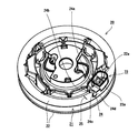
例えば、図6に示すように、半円筒状のアーチ部24が形成されてもよい。図6に示される例では、端末収容部23が省略されているが、端末収容部23を省略して簡素な形状としてもよい。
また、図7A及び図7Bに示すように、アーチ部24は、ロープリール20の側面に着脱可能な押さえ部材27によって形成されていてもよい。例えば、押さえ部材27の先端に返し形状を備えた係止爪27aを設け、ロープリール20の側面にこの係止爪27aに係合可能な取付穴28を設けてもよい。そして、係止爪27aを取付穴28に係合させることでロープリール20の側面に押さえ部材27を取り付けられるようにし、押さえ部材27を取り付けることでロープリール20の側面に環状に閉じられたアーチ部24が形成されるようにしてもよい。
このように着脱可能な押さえ部材27によってアーチ部24を形成すれば、ロープ30の端末を後から押さえ付けることができるので、組み付け性が向上する。また、このような構成においては、アーチ部24に対するロープ30の通しやすさを考慮する必要がないため、アーチ部24の幅をロープ30の径より大きくする必要がない。よって、ロープ30を押さえ込むようにアーチ部24の幅を設定し、ロープ30の保持力を高めることができる。
本出願は、2019年01月22日出願の日本特許出願特願2019-008412に基づくものであり、その内容はここに参照として取り込まれる。
Claims (6)
- リコイルスタータに設けられるロープリールであって、
ロープを巻き付けるように構成されたロープ保持溝と、
前記ロープ保持溝の両側に配置されたフランジ部と、
前記ロープ保持溝に巻き付けた前記ロープの端末を貫通させるように構成され、前記フランジ部に設けられた貫通穴と、
前記貫通穴に隣接して、前記ロープリールの側面に設けられたアーチ部と、
を備え、
前記アーチ部は、前記ロープを挿通するように構成され、該アーチ部が当該挿通されたロープを前記ロープリールの側面に沿って保持可能である。 - ロープの結び目を収容するように構成される端末収容部をさらに備え、
前記端末収容部は、前記貫通穴の周囲を囲むように形成される壁を含み、
前記アーチ部は、前記壁に形成された挿通穴と隣り合わせで形成されている、請求項1に記載のロープリール。 - 前記アーチ部は、前記ロープリールの側面にてロープを露出させる開口を含む、請求項1または2に記載のロープリール。
- 前記ロープが前記アーチ部を貫通するように構成され、
前記ロープリールの側面には、前記ロープの先端部の位置が確認されるように目盛が設けられている、請求項1~3のいずれか1項に記載のロープリール。 - 前記アーチ部は、前記ロープリールの側面に設けられる着脱可能な押さえ部材である、請求項1~4のいずれか1項に記載のロープリール。
- 請求項1~5のいずれか1項に記載のロープリールを備えたリコイルスタータであって、
前記アーチ部がエンジン側に配置されるように構成される、リコイルスタータ。
Priority Applications (4)
| Application Number | Priority Date | Filing Date | Title |
|---|---|---|---|
| EP20745294.7A EP3901446B1 (en) | 2019-01-22 | 2020-01-21 | Recoil stator rope reel and recoil stator |
| JP2020568173A JP7040823B2 (ja) | 2019-01-22 | 2020-01-21 | リコイルスタータ用のロープリールおよびリコイルスタータ |
| US17/424,863 US11566594B2 (en) | 2019-01-22 | 2020-01-21 | Rope reel for recoil starter, and recoil |
| CN202080010838.2A CN113330209A (zh) | 2019-01-22 | 2020-01-21 | 用于反冲起动器的绳索卷轴以及反冲件 |
Applications Claiming Priority (2)
| Application Number | Priority Date | Filing Date | Title |
|---|---|---|---|
| JP2019-008412 | 2019-01-22 | ||
| JP2019008412 | 2019-01-22 |
Publications (1)
| Publication Number | Publication Date |
|---|---|
| WO2020153379A1 true WO2020153379A1 (ja) | 2020-07-30 |
Family
ID=71736181
Family Applications (1)
| Application Number | Title | Priority Date | Filing Date |
|---|---|---|---|
| PCT/JP2020/001995 WO2020153379A1 (ja) | 2019-01-22 | 2020-01-21 | リコイルスタータ用のロープリールおよびリコイルスタータ |
Country Status (5)
| Country | Link |
|---|---|
| US (1) | US11566594B2 (ja) |
| EP (1) | EP3901446B1 (ja) |
| JP (1) | JP7040823B2 (ja) |
| CN (1) | CN113330209A (ja) |
| WO (1) | WO2020153379A1 (ja) |
Citations (5)
| Publication number | Priority date | Publication date | Assignee | Title |
|---|---|---|---|---|
| US2848987A (en) * | 1955-05-11 | 1958-08-26 | Motor Wheel Corp | Rewind engine starter |
| JPS53117840U (ja) * | 1977-02-26 | 1978-09-19 | ||
| US4940028A (en) * | 1989-02-08 | 1990-07-10 | White Consolidated Industries, Inc. | Recoil pull rope reel apparatus for internal combustion engines |
| JP2012251561A (ja) | 2012-08-22 | 2012-12-20 | Starting Industrial Co Ltd | リコイルスタータ |
| JP2019008412A (ja) | 2017-06-21 | 2019-01-17 | 三菱重工業株式会社 | プラント支援評価システム及びプラント支援評価方法 |
Family Cites Families (16)
| Publication number | Priority date | Publication date | Assignee | Title |
|---|---|---|---|---|
| US2348547A (en) | 1941-01-09 | 1944-05-09 | B M Kissel | Starting device |
| US3134376A (en) | 1961-05-08 | 1964-05-26 | Ohlsson & Rice Inc | Engine starter reel and method of making the same |
| JPS53117840A (en) | 1977-03-23 | 1978-10-14 | Matsushita Electric Ind Co Ltd | Cooling instrument |
| JPS5448221U (ja) * | 1977-09-10 | 1979-04-04 | ||
| JPS5848914B2 (ja) | 1977-09-24 | 1983-10-31 | ヤマハ株式会社 | 電子楽器のピッチベンド装置 |
| JPS59153971A (ja) | 1983-02-22 | 1984-09-01 | Sanshin Ind Co Ltd | リコイルスタ−タ |
| JPH0232868Y2 (ja) * | 1985-01-24 | 1990-09-05 | ||
| US4658775A (en) * | 1985-12-23 | 1987-04-21 | Eaton Stamping Company | Rope starter for engines |
| US4841929A (en) * | 1987-12-17 | 1989-06-27 | White Consolidated Industries, Inc. | Portable rotary power tool |
| US5676103A (en) | 1995-05-09 | 1997-10-14 | Starting Industrial Co., Ltd | Recoil starter |
| KR100962156B1 (ko) * | 2002-05-20 | 2010-06-10 | 스타팅 고교 가부시키가이샤 | 리코일 시동기 |
| US6959680B2 (en) * | 2002-07-24 | 2005-11-01 | Starting Industrial Co., Ltd. | Recoil starter |
| JP4523469B2 (ja) * | 2005-03-29 | 2010-08-11 | スターテング工業株式会社 | リコイルスタータ |
| US8291879B2 (en) * | 2008-12-03 | 2012-10-23 | Techtronic Outdoor Products Technology Limited | Recoil starter system |
| JP5101483B2 (ja) * | 2008-12-26 | 2012-12-19 | スターテング工業株式会社 | リコイルスタータ |
| JP5833910B2 (ja) * | 2011-12-19 | 2015-12-16 | スターテング工業株式会社 | リコイルスタータ機構 |
-
2020
- 2020-01-21 US US17/424,863 patent/US11566594B2/en active Active
- 2020-01-21 JP JP2020568173A patent/JP7040823B2/ja active Active
- 2020-01-21 WO PCT/JP2020/001995 patent/WO2020153379A1/ja unknown
- 2020-01-21 EP EP20745294.7A patent/EP3901446B1/en active Active
- 2020-01-21 CN CN202080010838.2A patent/CN113330209A/zh active Pending
Patent Citations (5)
| Publication number | Priority date | Publication date | Assignee | Title |
|---|---|---|---|---|
| US2848987A (en) * | 1955-05-11 | 1958-08-26 | Motor Wheel Corp | Rewind engine starter |
| JPS53117840U (ja) * | 1977-02-26 | 1978-09-19 | ||
| US4940028A (en) * | 1989-02-08 | 1990-07-10 | White Consolidated Industries, Inc. | Recoil pull rope reel apparatus for internal combustion engines |
| JP2012251561A (ja) | 2012-08-22 | 2012-12-20 | Starting Industrial Co Ltd | リコイルスタータ |
| JP2019008412A (ja) | 2017-06-21 | 2019-01-17 | 三菱重工業株式会社 | プラント支援評価システム及びプラント支援評価方法 |
Non-Patent Citations (1)
| Title |
|---|
| See also references of EP3901446A4 |
Also Published As
| Publication number | Publication date |
|---|---|
| EP3901446A4 (en) | 2022-10-12 |
| JPWO2020153379A1 (ja) | 2021-10-28 |
| US11566594B2 (en) | 2023-01-31 |
| JP7040823B2 (ja) | 2022-03-23 |
| CN113330209A (zh) | 2021-08-31 |
| US20220090570A1 (en) | 2022-03-24 |
| EP3901446A1 (en) | 2021-10-27 |
| EP3901446B1 (en) | 2024-07-10 |
Similar Documents
| Publication | Publication Date | Title |
|---|---|---|
| JP4860460B2 (ja) | ベルト取付方法、ベルト取付治具、ベルト着脱方法及びベルト着脱治具 | |
| JP4014998B2 (ja) | リコイルスタータ | |
| EP1384881B1 (en) | Recoil starter | |
| US20090255502A1 (en) | Starter System for Engine | |
| US6981482B2 (en) | Recoil starter | |
| US6782863B2 (en) | Spring release starter | |
| EP1312798B1 (en) | Recoil starter | |
| JP5418514B2 (ja) | ワイヤハーネス用のプロテクタ | |
| JP2005328847A (ja) | 動力工具用ブレーキシステム | |
| JP2008109837A (ja) | モータ装置 | |
| WO2020153379A1 (ja) | リコイルスタータ用のロープリールおよびリコイルスタータ | |
| JP4584220B2 (ja) | リコイルスタータ | |
| US20130186363A1 (en) | Recoil starter | |
| JP4069971B2 (ja) | エンジンのリコイルスタータ | |
| US20090007708A1 (en) | Rotary cable assembly for vehicles | |
| US7370623B1 (en) | Engine-powered tool with a tube for guiding a starter pull rope | |
| JP3892772B2 (ja) | リコイルスタータ | |
| JP2007306733A (ja) | ワイヤハーネス分岐部のプロテクタ | |
| WO2019187052A1 (ja) | リコイルスタータ | |
| CN211398236U (zh) | 一种释放机构驱动盒 | |
| TWI791715B (zh) | 雙軸承捲線器 | |
| JP4181468B2 (ja) | リコイルスタータ | |
| JP2512301Y2 (ja) | リコイルスタ―タ | |
| JP3892771B2 (ja) | リコイルスタータ | |
| JP2022116849A (ja) | ケーブル巻取装置及びケーブル巻取装置の組立方法 |
Legal Events
| Date | Code | Title | Description |
|---|---|---|---|
| 121 | Ep: the epo has been informed by wipo that ep was designated in this application |
Ref document number: 20745294 Country of ref document: EP Kind code of ref document: A1 |
|
| ENP | Entry into the national phase |
Ref document number: 2020568173 Country of ref document: JP Kind code of ref document: A |
|
| NENP | Non-entry into the national phase |
Ref country code: DE |
|
| ENP | Entry into the national phase |
Ref document number: 2020745294 Country of ref document: EP Effective date: 20210721 |