EP2039816B1 - Vliesstoff - Google Patents
Vliesstoff Download PDFInfo
- Publication number
- EP2039816B1 EP2039816B1 EP07743980.0A EP07743980A EP2039816B1 EP 2039816 B1 EP2039816 B1 EP 2039816B1 EP 07743980 A EP07743980 A EP 07743980A EP 2039816 B1 EP2039816 B1 EP 2039816B1
- Authority
- EP
- European Patent Office
- Prior art keywords
- nonwoven fabric
- portions
- raised ridge
- fibers
- fiber
- Prior art date
- Legal status (The legal status is an assumption and is not a legal conclusion. Google has not performed a legal analysis and makes no representation as to the accuracy of the status listed.)
- Not-in-force
Links
- 239000004745 nonwoven fabric Substances 0.000 title claims description 254
- 239000000835 fiber Substances 0.000 claims description 409
- 239000012530 fluid Substances 0.000 claims description 75
- 238000007664 blowing Methods 0.000 claims description 70
- 238000004519 manufacturing process Methods 0.000 claims description 62
- 238000007373 indentation Methods 0.000 claims description 61
- 238000000034 method Methods 0.000 claims description 45
- 239000005871 repellent Substances 0.000 claims description 9
- 238000005096 rolling process Methods 0.000 claims description 8
- 230000002940 repellent Effects 0.000 claims description 7
- XLYOFNOQVPJJNP-UHFFFAOYSA-N water Substances O XLYOFNOQVPJJNP-UHFFFAOYSA-N 0.000 claims description 7
- 239000007789 gas Substances 0.000 description 78
- 239000007788 liquid Substances 0.000 description 67
- 230000002745 absorbent Effects 0.000 description 37
- 239000002250 absorbent Substances 0.000 description 37
- 239000011295 pitch Substances 0.000 description 35
- -1 for example Substances 0.000 description 16
- 230000035807 sensation Effects 0.000 description 10
- 238000010438 heat treatment Methods 0.000 description 9
- 238000002844 melting Methods 0.000 description 9
- 230000008018 melting Effects 0.000 description 9
- 230000000717 retained effect Effects 0.000 description 8
- 229920001169 thermoplastic Polymers 0.000 description 8
- 239000004416 thermosoftening plastic Substances 0.000 description 8
- 229910052751 metal Inorganic materials 0.000 description 7
- 239000002184 metal Substances 0.000 description 7
- 229920000139 polyethylene terephthalate Polymers 0.000 description 7
- 239000005020 polyethylene terephthalate Substances 0.000 description 7
- 229910001220 stainless steel Inorganic materials 0.000 description 7
- 239000010935 stainless steel Substances 0.000 description 7
- 239000000306 component Substances 0.000 description 6
- 239000000463 material Substances 0.000 description 6
- 238000009941 weaving Methods 0.000 description 6
- 239000004698 Polyethylene Substances 0.000 description 5
- 238000009960 carding Methods 0.000 description 5
- 230000008602 contraction Effects 0.000 description 5
- 238000005520 cutting process Methods 0.000 description 5
- 229920000573 polyethylene Polymers 0.000 description 5
- 238000003892 spreading Methods 0.000 description 5
- TZCXTZWJZNENPQ-UHFFFAOYSA-L barium sulfate Chemical compound [Ba+2].[O-]S([O-])(=O)=O TZCXTZWJZNENPQ-UHFFFAOYSA-L 0.000 description 4
- 238000002788 crimping Methods 0.000 description 4
- 230000002349 favourable effect Effects 0.000 description 4
- 210000003608 fece Anatomy 0.000 description 4
- 229920001903 high density polyethylene Polymers 0.000 description 4
- 239000004700 high-density polyethylene Substances 0.000 description 4
- 229920001684 low density polyethylene Polymers 0.000 description 4
- 239000004702 low-density polyethylene Substances 0.000 description 4
- 239000003921 oil Substances 0.000 description 4
- 230000035515 penetration Effects 0.000 description 4
- 230000002829 reductive effect Effects 0.000 description 4
- 229920005989 resin Polymers 0.000 description 4
- 239000011347 resin Substances 0.000 description 4
- 239000007787 solid Substances 0.000 description 4
- 239000004743 Polypropylene Substances 0.000 description 3
- 230000006835 compression Effects 0.000 description 3
- 238000007906 compression Methods 0.000 description 3
- 230000004927 fusion Effects 0.000 description 3
- 239000011256 inorganic filler Substances 0.000 description 3
- 229910003475 inorganic filler Inorganic materials 0.000 description 3
- 230000035699 permeability Effects 0.000 description 3
- 229920001155 polypropylene Polymers 0.000 description 3
- IJGRMHOSHXDMSA-UHFFFAOYSA-N Atomic nitrogen Chemical compound N#N IJGRMHOSHXDMSA-UHFFFAOYSA-N 0.000 description 2
- VTYYLEPIZMXCLO-UHFFFAOYSA-L Calcium carbonate Chemical compound [Ca+2].[O-]C([O-])=O VTYYLEPIZMXCLO-UHFFFAOYSA-L 0.000 description 2
- RYGMFSIKBFXOCR-UHFFFAOYSA-N Copper Chemical compound [Cu] RYGMFSIKBFXOCR-UHFFFAOYSA-N 0.000 description 2
- 239000004677 Nylon Substances 0.000 description 2
- GWEVSGVZZGPLCZ-UHFFFAOYSA-N Titan oxide Chemical compound O=[Ti]=O GWEVSGVZZGPLCZ-UHFFFAOYSA-N 0.000 description 2
- 239000000443 aerosol Substances 0.000 description 2
- 229910052782 aluminium Inorganic materials 0.000 description 2
- XAGFODPZIPBFFR-UHFFFAOYSA-N aluminium Chemical compound [Al] XAGFODPZIPBFFR-UHFFFAOYSA-N 0.000 description 2
- 229920002678 cellulose Polymers 0.000 description 2
- 239000001913 cellulose Substances 0.000 description 2
- 150000001875 compounds Chemical class 0.000 description 2
- 229910052802 copper Inorganic materials 0.000 description 2
- 239000010949 copper Substances 0.000 description 2
- 238000004049 embossing Methods 0.000 description 2
- 238000010030 laminating Methods 0.000 description 2
- 238000002156 mixing Methods 0.000 description 2
- 239000000203 mixture Substances 0.000 description 2
- 229920001778 nylon Polymers 0.000 description 2
- 229920000728 polyester Polymers 0.000 description 2
- 230000002441 reversible effect Effects 0.000 description 2
- 239000002904 solvent Substances 0.000 description 2
- 229920002994 synthetic fiber Polymers 0.000 description 2
- 238000009423 ventilation Methods 0.000 description 2
- CIVCELMLGDGMKZ-UHFFFAOYSA-N 2,4-dichloro-6-methylpyridine-3-carboxylic acid Chemical compound CC1=CC(Cl)=C(C(O)=O)C(Cl)=N1 CIVCELMLGDGMKZ-UHFFFAOYSA-N 0.000 description 1
- IJALWSVNUBBQRA-UHFFFAOYSA-N 4-Isopropyl-3-methylphenol Chemical compound CC(C)C1=CC=C(O)C=C1C IJALWSVNUBBQRA-UHFFFAOYSA-N 0.000 description 1
- QTBSBXVTEAMEQO-UHFFFAOYSA-M Acetate Chemical compound CC([O-])=O QTBSBXVTEAMEQO-UHFFFAOYSA-M 0.000 description 1
- 229920000742 Cotton Polymers 0.000 description 1
- 206010070245 Foreign body Diseases 0.000 description 1
- 229920000914 Metallic fiber Polymers 0.000 description 1
- 239000004952 Polyamide Substances 0.000 description 1
- 239000004734 Polyphenylene sulfide Substances 0.000 description 1
- 229920001131 Pulp (paper) Polymers 0.000 description 1
- 229920000297 Rayon Polymers 0.000 description 1
- 238000010521 absorption reaction Methods 0.000 description 1
- 239000012190 activator Substances 0.000 description 1
- 239000000739 antihistaminic agent Substances 0.000 description 1
- 230000015572 biosynthetic process Effects 0.000 description 1
- 239000008280 blood Substances 0.000 description 1
- 210000004369 blood Anatomy 0.000 description 1
- 210000001124 body fluid Anatomy 0.000 description 1
- 239000010839 body fluid Substances 0.000 description 1
- 229910000019 calcium carbonate Inorganic materials 0.000 description 1
- 239000003795 chemical substances by application Substances 0.000 description 1
- 238000004140 cleaning Methods 0.000 description 1
- 238000004040 coloring Methods 0.000 description 1
- 238000001816 cooling Methods 0.000 description 1
- 239000008358 core component Substances 0.000 description 1
- 238000003851 corona treatment Methods 0.000 description 1
- 229960000525 diphenhydramine hydrochloride Drugs 0.000 description 1
- 230000000694 effects Effects 0.000 description 1
- 239000004744 fabric Substances 0.000 description 1
- 239000010419 fine particle Substances 0.000 description 1
- 238000005755 formation reaction Methods 0.000 description 1
- 210000004251 human milk Anatomy 0.000 description 1
- 235000020256 human milk Nutrition 0.000 description 1
- 239000003906 humectant Substances 0.000 description 1
- 230000002209 hydrophobic effect Effects 0.000 description 1
- 239000004615 ingredient Substances 0.000 description 1
- 230000002401 inhibitory effect Effects 0.000 description 1
- NFIDBGJMFKNGGQ-UHFFFAOYSA-N isopropylmethylphenol Natural products CC(C)CC1=CC=CC=C1O NFIDBGJMFKNGGQ-UHFFFAOYSA-N 0.000 description 1
- 230000005722 itchiness Effects 0.000 description 1
- 229940127554 medical product Drugs 0.000 description 1
- 230000002175 menstrual effect Effects 0.000 description 1
- 229910052757 nitrogen Inorganic materials 0.000 description 1
- 239000002245 particle Substances 0.000 description 1
- 238000009832 plasma treatment Methods 0.000 description 1
- 229920002647 polyamide Polymers 0.000 description 1
- 229920000069 polyphenylene sulfide Polymers 0.000 description 1
- 239000000843 powder Substances 0.000 description 1
- 239000002964 rayon Substances 0.000 description 1
- 229910052710 silicon Inorganic materials 0.000 description 1
- 239000010703 silicon Substances 0.000 description 1
- 239000003206 sterilizing agent Substances 0.000 description 1
- 239000000126 substance Substances 0.000 description 1
- 210000004243 sweat Anatomy 0.000 description 1
- 239000012209 synthetic fiber Substances 0.000 description 1
- 238000007669 thermal treatment Methods 0.000 description 1
- OGIDPMRJRNCKJF-UHFFFAOYSA-N titanium oxide Inorganic materials [Ti]=O OGIDPMRJRNCKJF-UHFFFAOYSA-N 0.000 description 1
- 229910000349 titanium oxysulfate Inorganic materials 0.000 description 1
- 210000000689 upper leg Anatomy 0.000 description 1
- 238000013022 venting Methods 0.000 description 1
Images


Classifications
-
- D—TEXTILES; PAPER
- D04—BRAIDING; LACE-MAKING; KNITTING; TRIMMINGS; NON-WOVEN FABRICS
- D04H—MAKING TEXTILE FABRICS, e.g. FROM FIBRES OR FILAMENTARY MATERIAL; FABRICS MADE BY SUCH PROCESSES OR APPARATUS, e.g. FELTS, NON-WOVEN FABRICS; COTTON-WOOL; WADDING ; NON-WOVEN FABRICS FROM STAPLE FIBRES, FILAMENTS OR YARNS, BONDED WITH AT LEAST ONE WEB-LIKE MATERIAL DURING THEIR CONSOLIDATION
- D04H1/00—Non-woven fabrics formed wholly or mainly of staple fibres or like relatively short fibres
- D04H1/70—Non-woven fabrics formed wholly or mainly of staple fibres or like relatively short fibres characterised by the method of forming fleeces or layers, e.g. reorientation of fibres
- D04H1/76—Non-woven fabrics formed wholly or mainly of staple fibres or like relatively short fibres characterised by the method of forming fleeces or layers, e.g. reorientation of fibres otherwise than in a plane, e.g. in a tubular way
-
- D—TEXTILES; PAPER
- D04—BRAIDING; LACE-MAKING; KNITTING; TRIMMINGS; NON-WOVEN FABRICS
- D04H—MAKING TEXTILE FABRICS, e.g. FROM FIBRES OR FILAMENTARY MATERIAL; FABRICS MADE BY SUCH PROCESSES OR APPARATUS, e.g. FELTS, NON-WOVEN FABRICS; COTTON-WOOL; WADDING ; NON-WOVEN FABRICS FROM STAPLE FIBRES, FILAMENTS OR YARNS, BONDED WITH AT LEAST ONE WEB-LIKE MATERIAL DURING THEIR CONSOLIDATION
- D04H1/00—Non-woven fabrics formed wholly or mainly of staple fibres or like relatively short fibres
- D04H1/40—Non-woven fabrics formed wholly or mainly of staple fibres or like relatively short fibres from fleeces or layers composed of fibres without existing or potential cohesive properties
- D04H1/58—Non-woven fabrics formed wholly or mainly of staple fibres or like relatively short fibres from fleeces or layers composed of fibres without existing or potential cohesive properties by applying, incorporating or activating chemical or thermoplastic bonding agents, e.g. adhesives
-
- D—TEXTILES; PAPER
- D04—BRAIDING; LACE-MAKING; KNITTING; TRIMMINGS; NON-WOVEN FABRICS
- D04H—MAKING TEXTILE FABRICS, e.g. FROM FIBRES OR FILAMENTARY MATERIAL; FABRICS MADE BY SUCH PROCESSES OR APPARATUS, e.g. FELTS, NON-WOVEN FABRICS; COTTON-WOOL; WADDING ; NON-WOVEN FABRICS FROM STAPLE FIBRES, FILAMENTS OR YARNS, BONDED WITH AT LEAST ONE WEB-LIKE MATERIAL DURING THEIR CONSOLIDATION
- D04H1/00—Non-woven fabrics formed wholly or mainly of staple fibres or like relatively short fibres
- D04H1/40—Non-woven fabrics formed wholly or mainly of staple fibres or like relatively short fibres from fleeces or layers composed of fibres without existing or potential cohesive properties
- D04H1/54—Non-woven fabrics formed wholly or mainly of staple fibres or like relatively short fibres from fleeces or layers composed of fibres without existing or potential cohesive properties by welding together the fibres, e.g. by partially melting or dissolving
-
- D—TEXTILES; PAPER
- D04—BRAIDING; LACE-MAKING; KNITTING; TRIMMINGS; NON-WOVEN FABRICS
- D04H—MAKING TEXTILE FABRICS, e.g. FROM FIBRES OR FILAMENTARY MATERIAL; FABRICS MADE BY SUCH PROCESSES OR APPARATUS, e.g. FELTS, NON-WOVEN FABRICS; COTTON-WOOL; WADDING ; NON-WOVEN FABRICS FROM STAPLE FIBRES, FILAMENTS OR YARNS, BONDED WITH AT LEAST ONE WEB-LIKE MATERIAL DURING THEIR CONSOLIDATION
- D04H1/00—Non-woven fabrics formed wholly or mainly of staple fibres or like relatively short fibres
- D04H1/70—Non-woven fabrics formed wholly or mainly of staple fibres or like relatively short fibres characterised by the method of forming fleeces or layers, e.g. reorientation of fibres
-
- Y—GENERAL TAGGING OF NEW TECHNOLOGICAL DEVELOPMENTS; GENERAL TAGGING OF CROSS-SECTIONAL TECHNOLOGIES SPANNING OVER SEVERAL SECTIONS OF THE IPC; TECHNICAL SUBJECTS COVERED BY FORMER USPC CROSS-REFERENCE ART COLLECTIONS [XRACs] AND DIGESTS
- Y10—TECHNICAL SUBJECTS COVERED BY FORMER USPC
- Y10T—TECHNICAL SUBJECTS COVERED BY FORMER US CLASSIFICATION
- Y10T428/00—Stock material or miscellaneous articles
- Y10T428/24—Structurally defined web or sheet [e.g., overall dimension, etc.]
- Y10T428/24479—Structurally defined web or sheet [e.g., overall dimension, etc.] including variation in thickness
- Y10T428/24521—Structurally defined web or sheet [e.g., overall dimension, etc.] including variation in thickness with component conforming to contour of nonplanar surface
- Y10T428/24537—Parallel ribs and/or grooves
-
- Y—GENERAL TAGGING OF NEW TECHNOLOGICAL DEVELOPMENTS; GENERAL TAGGING OF CROSS-SECTIONAL TECHNOLOGIES SPANNING OVER SEVERAL SECTIONS OF THE IPC; TECHNICAL SUBJECTS COVERED BY FORMER USPC CROSS-REFERENCE ART COLLECTIONS [XRACs] AND DIGESTS
- Y10—TECHNICAL SUBJECTS COVERED BY FORMER USPC
- Y10T—TECHNICAL SUBJECTS COVERED BY FORMER US CLASSIFICATION
- Y10T428/00—Stock material or miscellaneous articles
- Y10T428/24—Structurally defined web or sheet [e.g., overall dimension, etc.]
- Y10T428/24479—Structurally defined web or sheet [e.g., overall dimension, etc.] including variation in thickness
- Y10T428/2457—Parallel ribs and/or grooves
-
- Y—GENERAL TAGGING OF NEW TECHNOLOGICAL DEVELOPMENTS; GENERAL TAGGING OF CROSS-SECTIONAL TECHNOLOGIES SPANNING OVER SEVERAL SECTIONS OF THE IPC; TECHNICAL SUBJECTS COVERED BY FORMER USPC CROSS-REFERENCE ART COLLECTIONS [XRACs] AND DIGESTS
- Y10—TECHNICAL SUBJECTS COVERED BY FORMER USPC
- Y10T—TECHNICAL SUBJECTS COVERED BY FORMER US CLASSIFICATION
- Y10T428/00—Stock material or miscellaneous articles
- Y10T428/24—Structurally defined web or sheet [e.g., overall dimension, etc.]
- Y10T428/24479—Structurally defined web or sheet [e.g., overall dimension, etc.] including variation in thickness
- Y10T428/24595—Structurally defined web or sheet [e.g., overall dimension, etc.] including variation in thickness and varying density
-
- Y—GENERAL TAGGING OF NEW TECHNOLOGICAL DEVELOPMENTS; GENERAL TAGGING OF CROSS-SECTIONAL TECHNOLOGIES SPANNING OVER SEVERAL SECTIONS OF THE IPC; TECHNICAL SUBJECTS COVERED BY FORMER USPC CROSS-REFERENCE ART COLLECTIONS [XRACs] AND DIGESTS
- Y10—TECHNICAL SUBJECTS COVERED BY FORMER USPC
- Y10T—TECHNICAL SUBJECTS COVERED BY FORMER US CLASSIFICATION
- Y10T428/00—Stock material or miscellaneous articles
- Y10T428/24—Structurally defined web or sheet [e.g., overall dimension, etc.]
- Y10T428/24479—Structurally defined web or sheet [e.g., overall dimension, etc.] including variation in thickness
- Y10T428/24612—Composite web or sheet
Definitions
- the present invention relates to nonwoven fabric.
- nonwoven fabrics are used in a wide range of fields from hygienic products, such as baby diapers or feminine care articles (sanitary napkins) to cleaning products, such as wipers, or medical products, such as masks.
- hygienic products such as baby diapers or feminine care articles (sanitary napkins)
- cleaning products such as wipers
- medical products such as masks.
- nonwoven fabric is used in many different fields, but when actually used in products of each of those fields, it is necessary that the nonwoven fabric is manufactured with the properties and structures appropriate for their intended use.
- Nonwoven fabric is manufactured by forming a fibrous layer (fiber web) using a dry method or a wet method, and then bonding the fibers that compose the fibrous layer together using a chemical bonding method or a thermal bonding method.
- a method of bonding the fibers, that compose the fibrous layer in which a plurality of needles are repeatedly inserted into the fibrous layer, and there is a method wherein physical force, such as a blowing a race, is externally applied to the fibrous layer.
- Patent Document 1 discloses nonwoven fabric formed with an uneven surface by heat contraction of a predetermined layer by laminating and thermally bonding a plurality of fibrous layers composed of fibers having different heat contraction characteristics, and a manufacturing method of the same.
- nonwoven fabrics are integrated when forming the uneven layer by laminating a plurality of fibrous layers and thermally bonding each fibrous layer.
- the result is high-density fibers, with low liquid-penetrability in many of the thermally-bonded areas.
- the areas can also sometimes be turned into a film. If the thermally bonded area turns into a film, it is even more difficult for the liquid to penetrate downward quickly.
- a second fibrous layer composed of non-heat-shrinkable fibers is laminated to a single side or both sides of a first fibrous layer including heat-shrunk heat-shrinkable fibers, the first fibrous layer and the second fibrous layer being integrated by a plurality of thermal bonding portions for the nonwoven fabric disclosed in Patent Document 1.
- a plurality of convex portions is formed with the second fibrous layer projected by the heat shrinking of the first fibrous layer.
- It is an object of the present invention is to provide nonwoven fabric that easily pass liquids, such as excreta, and have concave and convex portions.
- the inventors recognized that it is possible to manufacture nonwoven fabric that easily pass liquids, and have concave and convex portions by moving fibers composing a fiber web, supported from a bottom surface side by a predetermined air-permeable support member, while blowing a gas from a top surface side, and completed the invention.
- nonwoven fabric as recited by Claim 1.
- a height in a thickness direction of each of the plurality of groove portions is no greater than 90% of a height in a thickness direction of each of the plurality of raised ridge portions.
- a predetermined raised ridge portion of the plurality of raised ridge portions has a different height in the thickness direction to an adjacent raised ridge portion.
- a peak of each of the plurality of raised ridge portions is substantially flat.
- the nonwoven fabric having rolling wave-forms in the first direction.
- the plurality of groove portions are provided a plurality indentations formed at predetermined spaces; and a plurality of projections that are regions excluding the plurality of indentations.
- a high in the thickness direction of each of the plurality of projections is less than a height in the thickness direction at each of the plurality of raised ridge portions.
- a high in the thickness direction of each of the plurality of indentations is a maximum of 90% of a height in the thickness direction at each of the plurality of projections.
- the first surface side and the second surface side at each of the plurality of projections are substantially flat.
- a length in the first direction at each of the plurality of projections is between 0.1 mm to 30 mm.
- a length in the first direction at each of the plurality of indentations is between 0.1 mm to 30 mm.
- a basis weight at each of the plurality of projections is less than a basis weight at each of the plurality of raised ridge portions, and a basis weight at each of the plurality of indentations is less than a basis weight at each of the plurality of projections.
- the basis weight at each of the plurality of projections is between 5 to 200 g/m 2 ; and the weight at each of the plurality of indentations is between 0 to 100 g/m 2 .
- the basis weight at each of the plurality of groove portions is less than the basis weight at each of the plurality of raised ridge portions.
- a fiber density at each of the plurality of groove portions is less than a fiber density at each of the plurality of raised ridge portions.
- a content percentage of fibers oriented in a second direction that is perpendicular to the first direction at the plurality of groove portions is greater than a content percentage of the fibers oriented in the first direction.
- a content percentage of fibers oriented in the first direction for each of the plurality of side portions at the plurality of raised ridge portions is greater than a content percentage of the fibers oriented in the second direction.
- a fiber composing the nonwoven fabric include water repellent fibers.
- the present invention provides nonwoven fabric formed with at least a groove portion and convex shapes, and allows the easy penetration of a predetermined liquid, such excreta.
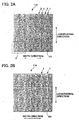
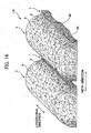
- Figs. 2A to 5 explain the first example not forming an embodiment of the nonwoven fabric of the present invention.
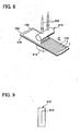
- a plurality of groove portions 1 is formed in parallel at substantially equidistant spacing along a first direction (hereinafter referred to as a longitudinal direction) on a first side of the nonwoven fabric 110 according to this example.
- the plurality of groove portions 1 is formed in parallel at equidistance spacing, but this is not meant to be a limitation.
- the spacing between adjacent groove portions 1 can be different. It is also acceptable that the spacing of the groove portions 1 is not parallel, but varied.
- raised ridge portions 2 are formed between two adjacent groove portions 1 and 1.
- a plurality of raised ridge portions 2 and 2 are formed in parallel at equidistant spacing, in the same way as the groove portions 1.
- the heights (the thickness direction) of the raised ridge portions 2 of the nonwoven fabric 110 of this example are substantially uniform, but it is acceptable that the heights of mutually adjacent raised ridge portions 2 to be different.
- the heights of the raised ridge portions 2 that are the distances in the thickness direction in the nonwoven fabric 110 of this example are between 0.3 and 15 mm; preferably between 0.5 and 5 mm.
- the lengths in a second direction (hereinafter referred to as the lateral direction or the width direction) that is perpendicular to a first direction per raised ridge portion 2 is between 0.5 to 30 mm; preferably 1.0 to 10 mm.
- the distance between peaks of adjacent raised ridge portions 2 and 2 is 0.5 to 30 mm; preferably between 3 to 10 mm.
- the heights (the distance in the thickness direction) of the nonwoven fabric 110 of an area formed of groove portions 1 are between 0 to 90% with regard to the heights of raised ridge portions 2, preferably between 1 to 50%; more preferably between 5 to 20%.
- the width of the groove portions 1 is between 0.1 to 30 mm; preferably from 0.5 to 10 mm.
- the distances (pitches) between adjacent groove portions 1 sandwiching the raised ridge portions 2 are between 0.5 to 20 mm; preferably from 3 to 10 mm.
- the groove portions 1 and raised ridge portions 2 As described above, it is difficult for a mass of a predetermined liquid to spread widely across the surface, if the nonwoven fabric 110 of this example is used as the surface sheet of an absorbent article, for example. Also, even if the raised ridge portions 2 are crushed under excessive external pressure, the spaces formed by the groove portions 1 are easily maintained. Therefore, even if a predetermined liquid is excreted while external pressure is being applied, it is difficult for the liquid to spread widely across the 110 of this embodiment are between 0.3 and 15 mm; preferably between 0.5 and 5 mm.
- the lengths in a second direction (hereinafter referred to as the lateral direction or the width direction) that is perpendicular to a first direction per raised ridge portion 2 is between 0.5 to 30 mm; preferably 1.0 to 10 mm. Also, the distance between peaks of adjacent raised ridge portions 2 and 2 is 0.5 to 30 mm; preferably between 3 to 10 mm.
- the heights (the distance in the thickness direction) of the nonwoven fabric 110 of an area formed of groove portions 1 are between 0 to 90% with regard to the heights of raised ridge portions 2, preferably between 1 to 50%; more preferably between 5 to 20%.
- the width of the groove portions 1 is between 0.1 to 30 mm; preferably from 0.5 to 10 mm.
- the distances (pitches) between adjacent groove portions 1 sandwiching the raised ridge portions 2 are between 0.5 to 20 mm; preferably from 3 to 10 mm.
- the groove portions 1 and raised ridge portions 2 As described above, it is difficult for a mass of a predetermined liquid to spread widely across the surface, if the nonwoven fabric 110 of this embodiment is used as the surface sheet of an absorbent article, for example. Also, even if the raised ridge portions 2 are crushed under excessive external pressure, the spaces formed by the groove portions 1 are easily maintained. Therefore, even if a predetermined liquid is excreted while external pressure is being applied, it is difficult for the liquid to spread widely across the surface.
- the nonwoven fabric 110 surface is formed to be uneven so there is less surface area for contact between the nonwoven fabric 110 and the skin, making it difficult for the liquid to widely adhere to the skin.
- the shapes of the raised ridge portions 2 There is no particular limitation to the shapes of the raised ridge portions 2. For example, dome shapes, trapezoidal shapes, triangular shapes, ⁇ shapes, and square shapes are all possible. To enhance the feel of the nonwoven fabric 110 against the skin, it is preferred that the area near the peak of the raised ridge portions 2 and the sides be curved surfaces. Also, to maintain the spaces of the groove portions 1 when the raised ridge portions 2 are crushed by external pressure, it is preferred that the widths of the raised ridge portions 2 be narrower from the bottom face to the peak surface.
- a preferred shape of the raised ridge portion 2 is a curved line (curved surface) such as a substantial dome shape.
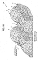
- areas are formed with different content percentages of fibers oriented in a first direction (longitudinally-oriented fibers) which oriented a predetermined longitudinal direction of the nonwoven fabric that are included in the fibers 101 composed the nonwoven fabric 110.
- a first direction longitudinally-oriented fibers
- Each of the areas with different content percentages include the groove portions 1, and the sides 8 and center portion 9 that compose the raised ridge portions 2, for example.
- orienting the fibers 101 in the first direction means that the fibers 101 are oriented within a +45° to -45° range with regard to a predetermined longitudinal direction, which is the direction (the machine direction, or MD) in which the nonwoven fabric or fiber web are fed via the machine that manufactures the nonwoven fabric. Fibers oriented to the first direction are called the longitudinally-oriented fibers. Furthermore, orienting the fibers 101 in a second direction (the width direction) means that the fibers 101 are oriented within a +45° to -45° range with regard to a predetermined width direction, which is perpendicular direction (the cross direction, or CD) to the MD direction. Fibers oriented to the second direction are called the laterally-oriented fibers.
- the sides 8 of the nonwoven fabric 110 are areas on both sides of the raised ridge portions 2.
- the fibers 101 at the sides 8 are formed so that the content percentage of the longitudinally-oriented fibers is higher than the content percentage of the longitudinally-oriented fibers at the central portion 9 (the area sandwiched by the sides 8 on the raised ridge portions 2).
- the content percentage of fibers oriented toward the longitudinal direction at the sides 8 is between 55 to 100%; more preferably between 60 to 100%. If the content percentage of the longitudinally-oriented fibers at sides 8 is less than 55%, it is possible for the sides 8 to experience stretching because of line tension. Also, the stretching of the sides 8 also causes stretching of the groove portions 1 and the central portion 9, described below, by line tension.
- the central portions 9 are areas sandwiched by the sides 8 on both sides of the raised ridge portions 2. These are areas where the content percentage of the longitudinally-oriented fibers is lower than the sides 8. It is preferred that the longitudinally-oriented fibers and the laterally-oriented fibers be moderately mixed at the central portions 9.
- the content percentage of the longitudinally-oriented fibers of the central portions 9 is a minimum of 10% less than the content percentage of the longitudinally-oriented fibers of the sides 8, and is a minimum of 10% greater than the content percentage of the longitudinally-oriented fibers in the bottom portion of the groove portions 1, described below.
- the content percentage of the longitudinally-oriented fibers at the central portions 9 is in a range between 40 to 80%.
- the groove portions 1, as described above, are areas where the fluid (for example, hot air) composed mainly of gas is directly blown upon, so the longitudinally-oriented fibers at the groove portions 1 are blown to the sides 8.
- the laterally-oriented fibers remain at the groove portions 1. For that reason, the content percentage of the laterally-oriented fibers is greater at the groove portions 1 than that of the longitudinally-oriented fibers.
- the content percentage of fibers oriented toward the longitudinal direction at the groove portions 1 is a minimum of 10% less than the content percentage of the laterally-oriented fibers at the central portions 9. Therefore, the content percentage of the longitudinally-oriented fibers is the least and the content percentage of the laterally-oriented fibers is the greatest at the groove portions 1 at the nonwoven fabric 110. Specifically, the content percentage of the laterally-oriented fibers is between 55 to 100%; preferably between 60 to 100%. When the content percentage of the laterally-oriented fibers is less than 55%, the basis weight of the groove portions 1, as described below, is low, so it is more difficult to increase the strength of the nonwoven fabric in the width direction. When doing so, if the nonwoven fabric 110 is used as the surface sheet of an absorbent article, for example, friction with a body during use of the absorbent article causes it to be misdirected to the width direction, and there is the danger that it can be damaged.
- the fiber density is adjusted to be less at the groove portions 1 compared to the raised ridge portions 2.
- the fiber density of the groove portions 1 can be freely adjusted by several conditions, such as the amount of blown fluid (for example hot air) composed of mainly gas, and the tension.
- the raised ridge portions 2 are formed to have a greater fiber density than the fiber density of the groove portions 1.
- the fiber density of the bottom portion of the groove portions 1 is less than 0.002 g/cm 3
- the nonwoven fabric 110 is used in an absorbent article, for example, the nonwoven fabric 110 can be easily damaged.
- the fiber density at the bottom portion of the groove portions 1 is greater than 0.18 g/cm 3 , it is difficult for the liquid to travel downward and will be retained at the groove portions 1, giving the user a moist sensation.
- Fiber density is adjusted to be greater at the raised ridge portions 2 compared to the groove portions 1. Furthermore, the fiber density of the raised ridge portions 2 can be freely adjusted by several conditions, such as the amount of blown fluid (for example hot air) composed of mainly gas, and the tension.
- Fiber density at the central portions 9 of the raised ridge portions 2 is between 0 to 0.20 g/cm 3 ; preferably between 0.005 to 0.20 g/cm 3 ; more preferably between 0.007 to 0.07 g/cm 3 for example. If the fiber density of the central portions 9 is less than 0.005 g/cm 3 , not only is it easier for the central portions 9 to be crushed by the weight of the liquid contained in the central portions 9 or by external pressure, but it also becomes easier for the liquid once absorbed in the absorbent article to reverse back, under the applied pressure. If fiber density at the central portions 9 is greater than 0.20 g/cm 3 , it is difficult for the liquid contained at the central portions 9 to travel downward and will be retained in the groove portions 9, giving the user a moist sensation.
- fiber density at the sides 8 of the raised ridge portions 2 can be freely adjusted by several conditions, such as the amount of blown fluid (for example hot air) composed of mainly gas, and the tension.
- the fiber density of the sides 8 is between 0 to 0.40 g/cm 3 ; preferably between 0.007 to 0.25 g/cm 3 ; more preferably 0.01 to 0.20 g/cm 3 for example. If fiber density at the sides 8 is less than 0.007 g/cm 3 , there are cases that the sides 8 will become stretched by line tension. If fiber density at the central portions 8 is greater than 0.40 g/cm 3 , it is difficult for the liquid contained at the sides 8 to travel downward. Thus, the liquid will be retained at the sides 8, giving the user a moist sensation.
- the average basis weight of the overall fiber of the nonwoven fabric 110 is between 10 to 200 g/m 2 ; preferably 20 to 100 g/m 2 .
- the average basis weight of the nonwoven fabric 110 is less than 10 g/m 2 , the surface sheet can be easily damaged while in use.
- the average basis weight of the nonwoven fabric 110 is greater than 200 g/m 2 , it is difficult for liquid to move downward.
- the basis weight of the fibers 101 at the groove portions 1 is adjusted to be less compared to the raised ridge portions 2.
- the basis weight of the bottom portion of the groove portions 1 is adjusted so that it is less compared to the average basis weight of entire nonwoven fabric including the bottom portion of the groove portions 1 and the raised ridge portions 2.
- the basis weight of the bottom of the groove portions 1 is between 3 to 150 g/m 2 ; preferably between 5 to 80 g/m 2 . If the basis weight of the bottom portion of the groove portions 1 is less than 3 g/m 2 , and the nonwoven fabric 110 are used as the surface sheet of an absorbent article, for example, the surface sheet can be easily torn during use. If the basis weight of the bottom of the groove portions 1 is greater than 150 g/m 2 , it is difficult for the liquid contained at the groove portions 1 to travel downward and will be retained in the groove portions 1, giving the user a moist sensation.
- the average basis weight of the fiber 101 at the raised ridge portions is adjusted to be greater compared to the groove portions 1.
- the basis weight of the central portions 9 at the raised ridge portions 2 is between 15 to 250 g/m 2 ; preferably between 20 to 120 g/m 2 . If the basis weight of the central portions 9 is less than 15 g/m 2 , not only is it easier for the central portions 9 to be crushed by the weight of the liquid contained at the central portions 9 or by external pressure, but it also becomes easier for the liquid absorbed in the absorbent article to reverse back, under the applied pressure. If the basis weight of the central portions 9 is greater than 250 g/m 2 , it is difficult for the liquid to travel downward and will be retained at the central portions 9, giving the user a moist sensation.
- the basis weight at the sides 8 of the raised ridge portions 2 can be freely adjusted by several conditions, such as the amount of blown fluid (for example hot air) composed of mainly gas, and the tension.
- the basis weight at the sides 8 is between 20 to 280 g/m 2 ; preferably between 25 to 150 g/m 2 . If the basis weight at the sides 8 is less than 20 g/m 2 , there is the possibility of the sides 8 experiencing stretching caused by line tension. If the basis weight at the sides 8 is greater than 280 g/m 2 , it is difficult for the liquid contained at the sides 8 to travel downward and will be retained in the sides 8, giving the user a moist sensation.
- the basis weight at the bottom of the groove portions 1 is adjusted so that it is less compared to the average basis weight of entire nonwoven fabric of the raised ridge portions 2 composed of the sides 8 and the central portions 9.
- the basis weight at the bottom of the groove portions 1 is a maximum of 90% of the average basis weight of the raised ridge portions 2; between 3 to 90%; more preferably between 3 to 70%. If the basis weight at the bottom of the groove portions 1 is greater than 90% of the average basis weight of the raised ridge portions 2, there will be greater resistance to the liquid which has seeped into the groove portions 1 to move downward of the nonwoven fabric 110, which can cause the liquid to leak from the groove portions 1.
- the basis weight at the bottom portion of the groove portions 1 is less than 3% with regard to the average basis weight of the raised ridge portions 2, and the nonwoven fabric is used as the surface sheet of an absorbent article, for example, the surface sheet can be easily damaged during use of the absorbent article.
- the groove portions 1 will allow the easy penetration of the liquid and the raised ridge portions 2 having a porous structure, make it difficult to retain the liquid.
- the fiber density of the fibers 101 of the bottom portion of the groove portions 1 is greater compared to the other areas and the basis weight is low, so it is appropriate for the penetration of liquid. Furthermore, the fibers 101 at the bottom portion of the groove portions 1 are oriented in the width direction so it is possible to prevent the liquid from flowing too far in the length direction of the nonwoven fabric 110 in the groove portions 1 and spreading widely.
- the fibers 101 are oriented in the width direction (CD orientation) of the groove portions 1, so regardless of the fact that the basis weight is less compared to other areas, the strength of the nonwoven fabric in the width directions (CD strength) is increased.
- the raised ridge portions 2 are adjusted so their basis weights are greater compared to other areas, and because this increases the number of fibers, the number of fusion points also increases and the porous structure is maintained.
- the content percentage of the laterally-oriented fibers of the bottom portion of the groove portions 1 is greater than that at the central portions 9, and the content percentage of the longitudinally-oriented fibers at the sides 8 is greater than that at the central portions 9.
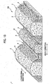
- the method for manufacturing the nonwoven fabric 110 of this example will be explained below with reference to Figs. 4A to 9 .
- the fiber web 100 is placed on a top surface of the mesh supporting member 210 which is an air-permeable support member. Said another way, the fiber web 100 is supported from a bottom side by the mesh supporting member 210.
- the nonwoven fabric 110 of this example by moving the mesh supporting member 210 in a predetermined direction while supporting the fiber web 100 and continuously blowing a gas from a top side of the fiber web 100 as it is being moved.
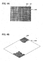
- the mesh supporting member 210 is formed by weaving a plurality of wires 211 of a predetermined thickness, which are non-air-permeable portions. By weaving the plurality of wires 211 to leave a predetermined space open, the mesh supporting member formed with a plurality of air-permeable holes 213 is obtained.
- the mesh supporting member 210 in Figs. 4A and 4B is formed with a plurality of holes 213 that have small diameters.
- the gas blows from the top side of the fiber web 100 and passes downward unhindered by the mesh supporting member 210.
- This mesh supporting member 210 prevents the fibers 101 from moving to a downward direction of the mesh supporting member 210 but does not greatly vary the flow of the fluid composed mainly of a gas being blown.
- the fibers 101 that compose the fiber web 100 are moved in a predetermined direction by the gas blow mainly from the top side. Specifically, downward movement is limited by the mesh supporting member 210 so the fibers 101 are moved in a direction along the surface of the mesh supporting member 210.
- the fibers 101 in the area blown by the gas are moved from that area to an area not blown by the gas in the surrounding area. Then, the area blown by the gas moves in a predetermined direction, so an area is formed on the fibers 101 where gas is continuously blown in a predetermined direction. The result is that the fibers 101 move to side directions in the consecutive areas.
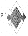
- the nonwoven fabric manufacturing apparatus 90 that manufactures the nonwoven fabric 110 of this example is provided with the air-permeable support member 200, and blowing means composed of a blowing unit 910 and an air pipe, not shown.
- the air-permeable support member 200 is configured to support the fiber web 100, which is the fiber aggregate, from one side.
- the blowing unit 910 is configured to blow a fluid composed mainly of a gas from the other side of the fiber web 100.
- the air pipe is configured to feed the fluid, composed mainly of a gas, to the blowing unit 910.
- the nonwoven fabric 110 is formed while the fiber web 100 is being sequentially moved by moving means.
- the moving means moves the fiber web 100 in a predetermined direction while the fiber web 100 is supported at one side by the air-permeable support member 200.
- the fiber web 100 is moved in a predetermined direction F while being blown by a fluid mainly composed of a gas.
- moving means an example is a conveyor 930 shown in Figs. 6 and 7 .
- the conveyor 930 is equipped with air-permeable belt 939 formed to a lateral, ring-shape mounted with the air-permeable support member 200, and rotors 931 and 933 arranged at both ends in the length direction, at the inner side of the air-permeable belt, that rotate the air-permeable belt 939 in a predetermined direction.
- the air-permeable support member 200 can be suitably replaced depending on the nonwoven fabric to be manufactured.
- the nonwoven fabric 110 of this example it is possible to use the mesh supporting member 210 described above as the air-permeable support member 200.
- the following will now explain using the mesh supporting member 210 described above as the air-permeable support member 200.
- the conveyor 930 moves the mesh supporting member 210 while it is supporting the fiber web 100 from the bottom side thereof. Specifically, as shown in Fig. 8 , the fiber web 100 is moved to pass the bottom side of the blowing unit 910. In addition, the fiber web 100 is moved to pass the inside of a heater unit 950, which is a heating means, and is opened at both sides.
- a heater unit 950 which is a heating means
- the blowing means is provided a pneumatic unit, not shown, and the blowing unit 910.
- the pneumatic unit, not shown, is linked to the blowing unit 910 via the air pipes 920.
- the air pipes 920 are connected to enable the passing of air to an upper side of the blowing unit 910.
- the blowing unit 910 is formed with a plurality of jet holes 913 at predetermined spaces.
- the gas that is fed from the pneumatic unit, not shown, to the blowing unit 910 via the air pipes 920 is linked blown out from the plurality of jet holes 913.
- the gas blown out from the plurality of jet holes 913 is blown continuously onto the top surface of the fiber web 100.
- the gas blown out from the plurality of jet holes 913 is blown continuously onto the top surface of the fiber web 100 being moved in the predetermined direction F by the conveyor 930. moved in the predetermined direction F by the conveyor 930.
- the suction by the suction unit 915 can be of a strength to the degree that the fibers 101 of the areas being blown by the fluid, composed mainly of a gas, are pushed to the mesh supporting member 210. It is possible to prevent the shape of the fiber web 100 from becoming disarrayed by the fluid, composed of mainly a gas, striking the non-air-permeable portions (the wire 211 of the mesh supporting member 210) of the air-permeable support member 200 and rebounding, by suctioning the fluid, composed of mainly a gas, by the suction unit 915. It is possible to convey to inside the heater unit 950 while maintaining the shape of the grooves (concave/convex portion) formed by air current. It is preferred that the suction by the suction unit 915 be performed until the fiber web 100 is conveyed into the heater unit 950.
- the fibers of the area being blown by the fluid composed, mainly of a gas are moved by being pushed to the mesh supporting member 210 side, so the fibers collect at the mesh supporting member 210 side.
- the fluid, composed mainly of a gas which is being blown striking and rebounding from the non-air-permeable portion (the wires 211 of the mesh supporting member 210) of the air-permeable support member 200, the fibers 101 partially align toward the thickness direction.
- the temperature of the fluid, composed mainly of a gas, blown from each of the jet holes 913 can be at room temperature, but to enable good formability of the groove portions (concave/convex), for example, it is possible to adjust the temperature to above the softening point of at least the thermoplastic fibers that compose the collection of fibers, and preferably above the softening point, to a temperature between +50°C and -50°C of the melting point. Because the fiber itself loses repulsive force when the fibers are softened, they can easily maintain their rearranged shapes by an air current. If the temperature is raised even further, the fibers will begin to melt together, making them maintain the shape of the groove portions (concave/convex) even more. This makes it possible to convey the fiber web to inside the heater unit 950 while maintaining the shape of the grooves (concave/convex).
- the airflow rate and temperature of the fluid, composed mainly of a gas being blown, and the amount of suction, the permeability of the mesh supporting member 210, and the adjustment of the basis weight of the fiber web 100 can vary the shapes of the raised ridge portions 2.
- the amounts of the fluid, composed mainly of a gas, being blown and being taken in (drawn in) are substantially equal, or if there is a greater amount of fluid, composed mainly of a gas, being taken in (drawn in)
- the backside of the raised ridge portions 2 of the nonwoven fabric 115 (nonwoven fabric 110) is formed according to the shape of the mesh supporting member 210. Therefore, if the mesh supporting member 210 is flat, the backside of the nonwoven fabric 115 (nonwoven fabric 110) would also be flat.
- the heater unit 950 which is the heating means, has both ends open in the predetermined direction F.
- the fiber web 100 (nonwoven fabric 110) set on the mesh supporting member 210 conveyed by the conveyor 930 is continuously moved with a predetermined time retained in the heated space formed inside the heater 950.
- the fibers 101 composing the fiber web 100 (nonwoven fabric 110) include thermoplastic fibers, it is possible to obtain nonwoven fabric 115 (nonwoven fabric 110) where fibers 101 are joined together by heat in the heater unit 950.
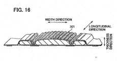
- Figs. 10 to 15 explain the second example of the nonwoven fabric of the present invention.
- the overall shapes of the nonwoven fabric in the second example are different compared to the first example.
- the shapes of the surfaces opposite to the surfaces formed by the raised ridge portions in the first embodiment are different compared to the first example.
- the shapes of the raised ridge portions in the third example are different compared to the first example.
- the point that openings are established in the groove portions 1 in the fourth example is different compared to the first example.
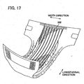
- Figs. 10 and 11 explain the second example not comprising an embodiment of the nonwoven fabric of the present invention.
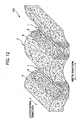
- the nonwoven fabric 116 of the second example are different from the first example in the point that the overall nonwoven fabric 116 are rolling in a wave shape.
- the following will now explain the points that are different to the first example.
- the nonwoven fabric 116 of the second example has rolling wave-shapes substantially perpendicular to the direction that the groove portions 1 and raised ridge portions extend.
- the method for manufacturing the nonwoven fabric 116 of the second example is the same as the method used for the first example, but the configuration of a mesh supporting member 260 that is the air-permeable support member is different.
- the mesh supporting member 260 of the second example is formed by weaving a plurality of wires 261 of a predetermined thickness, which are non-air-permeable. By weaving the plurality of wires 261 to leave predetermined spaces open, the mesh supporting members 260 formed of a plurality of air-permeable holes 263 is obtained.
- the mesh supporting member 260 are formed to have alternately rolling waves in a parallel direction of a Y axis, as shown in Fig. 11 , for example.
- the mesh supporting member 260 is a support member having rolling waves in a parallel direction on either the short direction or the long direction of the mesh supporting member 260.
- the mesh supporting member 260 in Fig. 11 is formed with a plurality of holes 263 that have small diameters, and the gas blows from the top side of the fiber web 100 passing downward unhindered by the mesh supporting member 260.
- This mesh supporting member 260 does not allow the fibers 101 to move to a downward direction of the mesh supporting member 260 without greatly varying the flow of the fluid composed mainly of a gas being blown.
- the mesh supporting member 260 itself has rolling waves, so the fiber web 100 is formed to a shape having rolls according to the shape of the mesh supporting member 260 by the fluid composed mainly of a gas blown from the top side of the fiber web 100.
- nonwoven fabric 116 by moving the fiber web 100 along the axis X direction while blowing the fluid composed mainly of a gas on the fiber web 100 set on the top surface of the mesh supporting member 260.
- the form of the rolling appearance in the mesh supporting member 260 can be freely set.
- the pitches between peaks of rolls in the axis X direction are between 1 to 30 mm; preferably between 3 to 10 mm.
- the level differences between the top and bottom portions of the rolls in the mesh supporting member 260 are between 0.5 to 20 mm; preferably between 3 to 10 mm.
- the shape of the cross-section of the axis X direction of the mesh supporting member 260 is not limited to a wave shape, as shown in Fig. 11 .
- each vertex of the peak portions and bottom portions of the rolls prefferably be a series of substantial triangular shapes forming sharp angles, or a series of concave and convex shapes that are substantially square-shapes so that each vertex of the peak portions and bottom portions are substantially flat.
- nonwoven fabric manufacturing apparatus 90 It is possible to manufacture the nonwoven fabric 116 of the second example using the nonwoven fabric manufacturing apparatus 90 described above.
- the explanations of the manufacturing method of the nonwoven fabric 110 and the nonwoven fabric manufacturing apparatus 90 can be of reference for the manufacturing method of the nonwoven fabric 116 in the nonwoven fabric manufacturing apparatus 90.
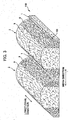
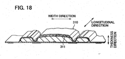
- Fig. 12 explains the first embodiment of the nonwoven fabric of the present invention.
- the shapes of the surfaces opposite to the surfaces formed with the raised ridge portions 2 of the nonwoven fabric 140 are different from those of the first example. The following will now explain the points that are different to the first example.
- the groove portions 1 and raised ridge portions 2 are alternately formed in parallel on the first surface side of the nonwoven fabric 140 of the first embodiment. Also, the area of the bottom surface of the raised ridge portions 2 is formed to project to the side that the raised ridge portions 2 projects, on the second surface side of the nonwoven fabric 140. Said another way, the areas of the bottom surfaces on the second side of the raised ridge portions 2 of the nonwoven fabric 140 form indented concave portions. Also, the areas of the second side at the bottom surface on the opposite side of the groove portions 1 are formed to convex portions that project to an opposite direction of the convex portion of the first side.
- the fiber web 100 is placed on the mesh supporting member 210 and moved along a predetermined direction while fluid, composed mainly of a gas, is blown on the fiber web, and the fluid, composed mainly of a gas, being blown is taken in (drawn in) from the bottom side of the mesh supporting member 210. Also, the amount of fluid, composed mainly of a gas, that is taken in (drawn in) is less than the amount of the fluid, composed mainly of a gas, that is blown.
- the fluid, composed mainly of a gas, that is blown is more than the fluid, composed mainly of a gas, that is taken in (drawn in)
- the fluid, composed mainly of a gas, that is blown slightly rebounds which can form the under surface side (bottom surface side) of the raised ridge portions 2 to project in the same direction as the raised ridge portions 2 of the top surface side of the raised ridge portions 2.
- the manufacturing method of the nonwoven fabric 140 of the first embodiment is the same as the one described in relation to the first example.
- the support members used in the manufacturing of the nonwoven fabric 140 can use the same ones as the mesh supporting member 210 in the first example. 2-3.
- Fig. 13 explains the third example not comprising an embodiment of the nonwoven fabric of the present invention.
- the nonwoven fabric 150 differ from the form of the first example in the point that raised ridge portions 2 and a second raised ridge portions 22 are formed having different heights on a first surface side of the nonwoven fabric 150. The following will explain the points that are different to the first example.
- the nonwoven fabric 150 of the third example is nonwoven fabric formed with a plurality of groove portions 1 on the first surface side of the nonwoven fabric 150.
- a plurality of raised ridge portions 2 is formed between each of a plurality of groove portions 1 formed at substantially equal spacing.
- a plurality of the second raised ridge portions 22 is alternately formed sandwiching the plurality of groove portions 1, between each of the adjacent plurality of raised ridge portions 2 that were sandwiching the plurality of groove portions 1. Said another way, the raised ridge portions 2 and second raised ridge portions 22 are alternately formed in parallel sandwiching the plurality of groove portions 1.
- the raised ridge portions 2 and second raised ridge portions 22 are areas that are not blown by the fluid, composed mainly of a gas, at the fiber web 100. They are areas that project relatively to the top side by forming the groove portions 1.
- the height of the second raised ridge portions 22 in the thickness direction of the nonwoven fabric 150 is less than the raised ridge portions 2.
- the length in the width direction is also formed to be narrow, but the fiber density, fiber orientation and basis weight are configured to be the same as the raised ridge portions 2.
- the raised ridge portions 2 and the second raised ridge portions 22 in the nonwoven fabric 150 were formed between each of the plurality of parallel formed groove portions 1.
- the raised ridge portions 2 is formed adjacent to the second raised ridge portions 22 sandwiching the groove portions 1.
- the second raised ridge portions 22 is formed adjacent to the raised ridge portions 2 sandwiching the groove portions 1.
- the raised ridge portions 2 and the second raised ridge portions 22 are alternately formed sandwiching the groove portions 1.
- the pattern of raised ridge portions 2, groove portions 1, second raised ridge portions 22, groove portions 1, raised ridge portions 2 is repeatedly formed. Note that the positional relationships of the raised ridge portions 2 and the second raised ridge portions 22 are not limited to this pattern. It is also possible to form a plurality of raised ridge portions 2 to be adjacent sandwiching the groove portions 1 on at least a portion of the nonwoven fabric 150. It is also possible to form a plurality of adjacent second raised ridge portions 22 sandwiching the groove portions 1.
- the manufacturing method for the nonwoven fabric 150 of the third example compared to the manufacturing method of the nonwoven fabric of the first example, is different in the form of the blowing nozzles 913 of the nonwoven fabric manufacturing apparatus 90.
- the nonwoven fabric 150 of the third example are formed by moving the fiber web 100 placed on the mesh supporting member 210 while blowing a fluid, composed mainly of a gas, on the fiber web 100.
- the groove portions 1, raised ridge portions 2 and the second raised ridge portions 22 are formed when the fluid, composed mainly of a gas, is blown, and these formations can be freely changed depending on the blowing nozzles 913 of the fluid, composed mainly of a gas, in the nonwoven fabric manufacturing apparatus 90.
- the nonwoven fabric 150 shown in Fig. 13 can be manufactured by the nonwoven fabric manufacturing apparatus 90 by adjusting the spacing of the blowing nozzles 913. For example, by narrowing the space of the blowing nozzles 913 more than the blowing nozzles 913 of the first example, it is possible to form the second raised ridge portions 2 with a lower thickness direction than the raised ridge portions 2. Also, by widening the space of the blowing nozzles 913 more than the blowing nozzles 913 of the first example, it is possible to form raised ridge portions with a higher thickness direction than the raised ridge portions 2.
- the raised ridge portions 2 and second raised ridge portions 22 can be alternately arranged on the nonwoven fabric 150 sandwiching the groove portions 1.
- the spacing of the blowing nozzles 913 is not meant to be limited to this configuration. It is possible to freely form the heights of the raised ridge portions of the nonwoven fabric and to orient the second raised ridge portions 22.
- Figs. 14 and 15 explain the fourth example not comprising an embodiment of the nonwoven fabric of the present invention.
- the nonwoven fabric 170 of the fourth example differ from the first example in the point that indentation 3A and projection 4A are formed in the groove portions 1 formed on one surface side of the nonwoven fabric 170.
- the following will explain the points that are different to the first example.
- a plurality of groove portions 1 are formed in parallel at substantially equal spaces at a first surface side of the nonwoven fabric 170 of the fourth example. Also, each of a plurality of raised ridge portions 2 is formed between each of a plurality of groove portions 1. Furthermore, in the groove portions 1, a plurality of indentation 3A is formed at substantially equal spaces along the groove portions 1, and each of a plurality of projection 4A is formed between each of the plurality of indentation 3A.
- the indentation 3A is formed at substantially equal spaces, but the spacing is not limited to that and can be a different space. As shown in Fig. 14 , the indentation 3A show openings, but this can vary according to conditions such as the amount and strength of the fluid, composed mainly of a gas, being blown, and the amount of suction.
- the heights in the thickness direction of the nonwoven fabric 170 in the indentation 3A is no greater than 90% of the height in the thickness direction of the nonwoven fabric of the projection 4A, preferably between 0 to 50%; more preferably between 0 to 20%.
- the height of 0% indicates that the indentation 3A is an opening.
- the lengths in the length direction and the width direction of one indentation 3A are between 0.1 to 30 mm; preferably between 0.5 to 10 mm. Also, the pitches of adjacent indentation 3A mutually sandwiching the projection 4A are between 0.5 to 30 mm; preferably between 1 to 10 mm.
- the heights in the thickness direction of the nonwoven fabric 170 at the projection 4A are equal to or less than the heights in the thickness direction of the nonwoven fabric 170 of raised ridge portions 2, preferably between 20 to 100%; more preferably between 40 to 70%.
- the lengths of the nonwoven fabric 170 of projection 4A in the length and the width directions are between 0.1 to 30 mm; preferably between 0.5 to 10 mm.
- the pitches of adjacent projection 4A mutually sandwiching the indentation 3A are between 0.5 to 30 mm; preferably between 1 to 10 mm.
- the cross-sectional shape in the length direction of the nonwoven fabric of the projection 4A is substantially a square shape.
- the cross-sectional shape in the length direction of projection 4A is not limited to being a square. It is not limited to being a dome shape, trapezoidal shape, triangular shape, or ⁇ shape, but to suppress the spreading of the predetermined liquid in the groove portions 1, a substantial square shape is preferred.
- the peak surface of the projection 4A is preferred to be a plane or a curved surface.
- the cross-sectional shape in the length direction of the nonwoven fabric of the indentation 3A can be dome-shaped, trapezoid-shaped, ⁇ shaped, or square shaped, or the inversion of these shapes. There is no particular limitation to the shape. If the indentation 3A is an opening, it is preferred because it suppresses the spreading of the predetermined liquid in the groove portions 1, even if excess external pressure is applied or a predetermined liquid with a high viscosity is charged.
- the fibers of the projection 4A in the groove portions 1 are oriented along the width direction of the overall groove portions 1.
- the fluid composed mainly of a gas, that is blown causes the longitudinally-oriented fibers to be blown to the raised ridge portions 2 side, or the laterally-oriented fibers to be blown to the projection 4A side, in the region that is the opening. Therefore, the fibers 101 in the area around the opening are oriented to envelope the surrounding of the opening. For that reason, it is difficult for the opening to be crushed and plugged even when external pressure is applied.
- the projection 4A is formed with a greater fiber density than the indentation 3A.
- the fiber densities of the indentation 3A and projection 4A are freely adjusted depending on conditions such as the amount of the blown fluid composed mainly of a gas, and the tension, in the same way as the raised ridge portions 2 and groove portions 1 of the first example. Note that the indentation 3A does not have to be an opening.
- the fiber density of the indentation 3A is a maximum of 0.20 g/cm 3 ; preferably between 0.0 to 0.10 g/cm 3 .
- the fiber density of 0.0 g/cm 3 indicates that the indentation 3A is an opening. If the fiber density of the indentation 3A is greater than 0.20 g/cm 3 , the predetermined liquid charged to the groove portions 1 can build-up once in the indentation 3A.
- the fiber density of the projection 4A is between 0.005 to 0.20 g/cm 3 ; preferably between 0.007 to 0.10 g/cm 3 . If the fiber density of the projection 4A is less than 0.005 g/cm 3 , and the raised ridge portions 2 are crushed under excess external pressure, the projection 4A would also be crushed, making it difficult to maintain a space formed by the indentation 3A in the groove portions 1.
- the fiber density of the projection 4A is greater than 0.20 g/cm 3 , the predetermined liquid charged to the groove portions 1 will build-up in the projection 4A, and if it directly touches the skin because of excess external pressure applied to the nonwoven fabric 170, the user would experience a moist sensation.
- the indentation 3A in the groove portions 1 is formed to have a lower basis weight of the fibers 101 compared to the raised ridge portions 2 and the projection 4A. In other words, the basis weight is formed to be lowest for the indentation 3A, in the nonwoven fabric 170.
- the basis weight of the indentation 3A is between 0 to 100 g/m 2 ; preferably between 0 to 50 g/m 2 .
- the basis weight of the indentation 3A is 0 g/m 2 indicates that the indentation 3A is an opening. If the basis weight of the indentation 3A is greater than 100 g/m 2 , the predetermined liquid charged to the groove portions 1 can build-up once in the indentation 3A.
- the predetermined liquid can easily leak from the indentation 3A and spread to the projection 4A, in the groove portions 1, and spread to the surface of the nonwoven fabric 170, causing the skin to be dirtied.
- the projection 4A is formed with a greater basis weight compared than the indentation 3A.
- the basis weight of the projection 4A is between 5 to 200 g/m 2 ; preferably between 10 to 100 g/m 2 . If the basis weight of the projection 4A is less than 5 g/m 2 , and the raised ridge portions 2 are crushed under excess external pressure, the projection 4A would also be crushed, making it difficult to maintain a space formed by the indentation 3A in the groove portions 1.
- the basis weight of the projection 4A is greater than 200 g/m 2 , the predetermined liquid dropped into the groove portions 1 will build-up in the projection 4A, and if it directly touched the skin because of excess external pressure applied to the nonwoven fabric 170, the user would experience a moist sensation.
- the fiber web 100 is placed on a top surface of the supporting member 270 shown in Fig. 15 which is an air-permeable support member, in the same way as was described for the first example. Said another way, the fiber web 100 is supported from a bottom side by the supporting member 270.
- the fiber web 100 is moved in a predetermined direction while being supported by the supporting member 270. It is possible to manufacture the nonwoven fabric 170 by blowing a fluid, composed mainly of a gas, from the top surface of the fiber web 100 being moved.
- the supporting member 270 is a spiral-weave air-permeable net formed by alternately wrapping wire 272 of a predetermined thickness around another wire 271 of a predetermined thickness lined up substantially parallel, to bridge a plurality of wires 271.
- the portions of the wire 271 and 272 in the supporting member 270 are non-air-permeable.
- the portions surrounded by the wire 271 and 272 in the supporting member 270 are holes 273.
- wires 271 and 272 which are not air-permeable to allow the passage of a portion of the fluid, by creating gaps in the adjoined wires, of the plurality of wires (for example two wires) as the wires 271 and 272.
- the degree of air-permeability of the non-air-permeable wires 271 and 272 is a maximum of 90% of the degree of air-permeability of the holes 273; preferably between 0 to 50%; more preferable between 0 to 20%.
- 0% indicates that the fluid substantially cannot pass through.
- the degree of air-permeability of the areas such as the holes 273 that are the air ventilation portions is between 10,000 to 60,000 cc/cm 2 •min; preferably between 20,000 to 50,000 cc/cm 2 •min.
- a vent is formed by cutting out a metal plate or the like, for example, as a air-permeable support member, the resistance of the fluid to the plate portion would be eliminated, so there would be air-permeability that is greater than the numerical values described above.
- the area that is not air-permeable it is preferable for the area that is not air-permeable to have a greater surface slippage than the area that forms the venting portion.
- the fibers 101 By being highly slippery, it is easy for the fibers 101 to move in the area where the area being blown by the fluid, composed mainly of a gas, and the unventilated portion intersect so that it is possible to increase the formability of the indentation 3A and the projection 4A.
- the groove portions 1 if fluid, composed mainly of a gas, is blown at the intersecting portion of the wire 271 and the wire 272 in the supporting member 270, the fluid, composed mainly of a gas, rebounds at the intersecting portion. For that reason, the fibers 101 supported at the intersecting portion is blown to the front, back and left and right to form the indentation 3A.
- the groove portions 1 are formed by blowing fluid at the area on the upper surface of the hole 273 of the supporting member 270, and by forming the indentation 3A at the groove portions 1, the projection 4A that projects relatively is formed.
- the fibers 101 oriented substantially parallel in the groove portions 1 is blown to the raised ridge portions 2 side, and the fibers 101 oriented in the direction that intersects the extending direction of the groove portions 1 is blown to the projection 4A side. For that reason, the basis weight is less at the indentation 3A.
- the fibers 101 are blown from the indentation 3A, forming the projection 4A with a greater basis weight than the indentation 3A.
- the nonwoven fabric 170 first, manufacture the nonwoven fabric formed with the groove portions 1 and the raised ridge portions 2 as described in relation to the first example, then it is possible to manufacture the nonwoven fabric 170 by forming the indentation 3A and projection 4A by applying an embossing finish to the groove portions 1.
- the relationship of the fiber density and the basis weight of the indentation 3A and the projection 4A is the opposite of the relationship described in relation to the present example. In other words, the fiber density and basis weight of the projection 4A is less than the fiber density and basis weight of the indentation 3A.
- the nonwoven fabric 170 As another method for manufacturing the nonwoven fabric 170, form concave and convex portions such as the raised ridge portions 2 and groove portions 1 in the fiber web 100 in advance. Then, it is possible to blow the fluid, composed mainly of a gas, onto another overlapped fiber web whose fibers have a degree of freedom. Thus, the raised ridge portions and groove portions are formed at the upper layer of fiber web by blowing fluid, but the concave and convex portions formed at the bottom layer of fiber web with a low basis weight at the groove portions are exposed, forming the projection and indentation of this example. Then, heat treatment integrates the top layer of the fiber web and lower layer of fiber web.
- nonwoven fabric manufacturing apparatus 90 It is possible to manufacture the nonwoven fabric 170 of this example using the nonwoven fabric manufacturing apparatus 90 described above.
- the explanations of the manufacturing method of the nonwoven fabric 110 and the nonwoven fabric manufacturing apparatus 90 can be of reference for the manufacturing method of the nonwoven fabric 170 in the nonwoven fabric manufacturing apparatus 90.
- the mixing ratio of the fiber A and the fiber B is 70:30, and use a fiber aggregate adjusted to a basis weight of 40 g/m 2 .
- the nonwoven fabric is highly flexible. Specifically, if the oven temperature is set to 120°C, for example, the low-density polyethylene will melt and thermally bond the fibers together at the intersecting points of the fibers A, and the intersecting points of the fibers A and fibers B. Also, because there is a greater volume of low-density polyethylene fibers at the intersection of the fibers A than at the intersections of the fibers A and the fibers B, the strength of the intersecting points of the fibers A is grater than the strength of the intersecting points of the fibers A and the fibers B.
- the high-density polyethylene of the fibers B does not melt, so the fibers do not become thermally bonded.
- the relationship of the strength of the intersecting points at this time is that the strength of the intersecting points of the fibers A is greater than the strength of the intersecting points of the fibers A and the fibers B, and the strength of the intersecting points of the fibers A and the fibers B is greater than the strength of the intersecting points of the fibers B.
- the blowing nozzles 913 shown in Fig. 9 have a diameter of 1.0 mm, and are formed in plurality at a pitch of 6.0 mm. Also, the shapes of the blowing nozzles 913 are substantially circles, and the cross-sectional shapes of the blowing nozzles 913 are cylindrical. The widths of the blowing nozzles 913 are 500 mm. These blow hot air with the conditions of temperatures at 105°C and air capacity of 1200 l/minute.
- a fiber web is created by opening using a carding method at a speed of 20 m/minute and cutting the fiber web to widths of 450 mm. Also, the fiber web is conveyed onto a 20 mesh air-permeable net at a speed of 3 m/minute. Also, with the manufacturing conditions using the blowing unit 910 and blowing nozzles 913 described above and hot air blown onto the fiber web on the one hand, the hot air is being taken in (drawn in) from below the air-permeable net at an amount that is less than the blown hot air. Thereafter, with the fiber web being conveyed by the air-permeable net, it is conveyed inside the oven set to a temperature of 125°C and hot blast air amount of 10 Hz, for approximately 30 seconds.
- the fiber configuration is the same as the first example.
- the fiber web of the fiber configuration described above is placed on the air-permeable net, then conveyed inside the oven set to a temperature of 125°C, and a hot blast air amount of 10 Hz, for 30 seconds. Immediately after conveying from the oven (after approximately two seconds), hot air is blown with the conditions of a temperature of 120°C and an air capacity of 2200 l/minute, with the design of the blowing unit 910 and blowing nozzles 913 described above.
- the fiber configuration is the same as the first example.
- blowing unit 910 and blowing nozzles 913 described above, while hot air is blown with the conditions of a temperature of 105°C, and hot blast air amount of 1000 l/minute, the hot air is being taken in (drawn in) from below the air-permeable net at an amount that is substantially the same, or slightly greater than the blown hot air.
- the fiber configuration is the same as the first example.
- An air current is blown with the conditions of a temperature of 80°C and an air capacity of 1800 l/minute, with the design of the blowing unit 910 and blowing nozzles 913 described above. Also, while the fiber web of the fiber configuration described above is moved in the length direction at a speed of 3 m/minute, needles arranged in a staggered pattern at pitches of 5 mm in the length direction, and at 5 mm in the width direction partially-entangle the fibers by needle punches at a speed of 200 times/minute. Then, air is blow with the manufacturing conditions by the blowing unit 910 and the blowing unit 913 described above. Also, at the same time this in taken in (drawn in) at substantially the same amount or a slightly amount greater than the hot blast air amount, from below the air-permeable net.
- the mixing ratio of the fiber A and the fiber B is 70:30, and use a fiber aggregate adjusted to a basis wight of 40 g/m 2 .
- the blowing nozzles 913 shown in Fig. 9 have a diameter of 1.0 mm, and are formed in plurality at a pitch of 6.0 mm. Also, the shapes of the blowing nozzles 913 are substantially circles, and the cross-sectional shapes of the blowing nozzles 913 are cylindrical. The widths of the blowing unit 910 are 500 mm. These blow hot air with the conditions of temperatures at 205°C and air capacity of 1000 l/minute.
- a stainless sleeve cut out in the shape of a lateral rectangle with rounded corners at a length of 2 mm and width of 70 mm is used for the supporting body.
- the pattern taken from the above with this sleeve is arranged in a lattice shape leaving open spaces of 3 mm in the machine direction, and 3 mm in the cross direction. Also, the thickness of the sleeve is 0.5 mm.
- the fiber aggregate of the fiber configuration described above creates a fiber web by opening using a card apparatus at a speed of 20 m/minute and cutting the fiber web to widths of 450 mm. Also, the fiber web is conveyed with a 20 mesh air-permeable net at a speed of 3 m/minute. An air current is blown with the conditions of a temperature of 105°C and an air capacity of 1200 l/minute, with the design of the blowing unit 910 and blowing nozzles 913 described above. Also, the air current is taken in (drawn in) at a smaller amount than the hot blast air amount, from below the air-permeable net. Thereafter, with the fiber web being conveyed by the air-permeable net, it is conveyed inside the oven set to a temperature of 125°C and hot blast air amount of 10 Hz, for approximately 30 seconds.
- the fiber configuration is the same as the fourth example.
- the fiber configuration disclosed in the fifth working example is charged to the same sleeve, then conveyed inside the oven set to a temperature of 125°C, and a hot blast air amount of 10 Hz, for 30 seconds, while being conveyed by the air-permeable net.
- an air current is blown with the conditions of a temperature of 120°C and an air capacity of 2000 l/minute, with the design of the blowing unit 910 and blowing nozzles 913 described above in relation to the fifth working example.
- a hot air blast is applied to the fiber web prior to the thermal fusion of the fibers being thermally bonded, so the hot air is blown when the degree of freedom of the fibers is low.
- hot air is blown after the fibers are changed into nonwoven fabric, hot air is blown to maintain the framework formed by the thermal bonding of the fibers to a certain degree, to form the raised ridge portions and the groove portions. For that reason, it is possible to increase the maintainability of the concave and convex shapes under external pressure.
- the nonwoven fabric can be used as a surface sheet for an absorbent article, such as a sanitary napkin, a liner, and diapers, for example.
- the raised ridge portions can either be the skin surface side, or the back surface side, but by applying the raised ridge portions to the skin surface side, the surface area in contact with the skin is reduced thereby making it difficult for the user to experience a moist sensation from body fluids.
- the nonwoven fabric of the present invention can be used as the middle sheet arranged between the surface sheet and the absorbent body in the absorbent article.
- the nonwoven fabric of the present invention As the middle sheet, the surface area in contact with the absorbent body is reduced for the middle sheet and the surface sheet, and it is possible to reduce the return of liquids from the absorbent body to the surface sheet. Additionally, it is possible to use the nonwoven fabric of the present invention as side sheets of an absorbent article, the external surface (the external wrapping material) of diapers or the like, or female members such as hook-and-loop fastner. Using the nonwoven fabric of the present invention in these applications increases the feel of the product against the skin by lowering the surface area in contact with the skin, and improves cushioning. The nonwoven fabric can also be used in a wide range of applications such as wipers to remove dirt or grime adhering to a floor or a body, as a mask or as a breast-milk pad or the like.
- the convex and concave nonwoven fabric can be used as surface sheets 301 and 302 of an absorbent article, for example, as shown in Figs. 16 and 17 .
- the nonwoven fabric is arranged so that the surfaces formed with the raised ridge portions are on the skin side.
- the nonwoven fabric When the nonwoven fabric is used as the surface sheets 301 and 302 of the absorbent article, and a predetermined liquid is excreted, that liquid mainly seeps into the groove portions. For example, even if the excreted liquid is viscous and contains solid particles, the liquid will fall into the groove portions, so it is possible to suppress the liquid from spreading widely over the surface. Also, the nonwoven fabric of the present invention are formed to be uneven by the groove portions 1 and the raised ridge portions, making it possible to lower the surface area that comes into contact with the skin, so the feeling against the skin is favorable. Also, even if the liquid once absorbed by the absorbent article returns back to the surface sheet, it is difficult for it to adhere widely to the skin.
- the majority of the fibers in the groove portions are oriented in the width direction, there is high tensile strength to the width direction, which prevents the surface sheets 301 and 302 from becoming damaged when force, such as friction, is applied at the width direction while the absorbent article is in use.
- the sides of the raised ridge portions are formed by the fibers of the groove portions being moved when forming the groove portions, so the fibers are compacted together, thereby increasing their stiffness.
- the central portion of the raised ridge portions include many fibers oriented in the thickness direction, so this prevents them from being easily crushed when a load is applied to the raised ridge portions. Even if the raised ridge portions are crushed by a load, they have a high compression recoverability.
- the nonwoven fabric of the present invention it is possible to use the nonwoven fabric as a middle sheet 311 of an absorbent article, for example, as shown in Fig. 18 .
- the nonwoven fabric is arranged so that the surface formed with the raised ridge portions are at the surface sheet 310 side.
- the contact ratio of the middle sheet 311 and the surface sheets 310 is low, so it is difficult for the liquid to return to the surface sheets 310 and adhering widely to the skin.
- the central portion of the raised ridge portions in the middle sheet 311 included many fibers that are oriented in the thickness direction compared to the sides and the groove portions, and because the peaks of the raised ridge portions and surface sheets 310 are adjacent, it is easy for the liquid remaining in the surface sheets 310 to be drawn in the thickness direction. This makes it difficult for the liquid to be retained at the surface sheets 310.
- the nonwoven fabric of the present invention it is possible to use the nonwoven fabric as an external surface (external wrapping material 321) of an absorbent article, for example, as shown in Fig. 19 .
- the nonwoven fabric is arranged so that the surfaces formed with the raised ridge portions are on outer side of the absorbent article.
- the feeling against the skin is favorable when the absorbent article using the nonwoven fabric of the present invention as the external wrapping material 321 is touched by hand. Also, because the basis weight and the fiber density of the groove portions is less, it has superior air permeability.
- the fiber aggregate is formed by substantial sheet shapes.
- the fibers that compose the fiber aggregate have a degree of freedom.
- the fiber aggregate has a degree of freedom between the fibers.
- the degree of freedom between the fibers means that the fiber web of the fiber aggregate can be moved freely by the fluid.
- This fiber aggregate can be formed by blowing to form fibrous layers of a predetermined thickness of fibers blended of a plurality of fiber types. For example, it is possible to blow each of a plurality of different fibers to form a fiber layer that is laminated a plurality of times.
- a fiber web formed by the carding method, or a fiber web prior to the solidifying of thermal bonded fibers are examples of the fiber aggregate of the present invention.
- Webs formed by an air laid method, or a fiber web prior to the solidifying of thermal bonded fibers are also examples.
- Another example is a fiber web prior to the solidifying of thermal bonded fibers embossed by a point bonding method.
- Yet another example can be an embossed fiber aggregate prior to fiber forming by a spunbonding method, or an embossed fiber aggregate prior to the solidifying of thermal bonded fibers.
- a fiber web partially entangled, formed by a needlefelt method is yet another example.
- a fiber aggregate can also be formed by a meltblown method prior to the solidifying of thermal bonded fibers. Or there is the fiber aggregate formed by a solvent bonding method prior to the solidifying of thermal bonded fibers.
- a fiber web that is formed by the carding method that uses a comparatively long fiber that can easily be reoriented by an air (or a gas) current is used.
- a web prior to being formed by entangling, with a high degree of freedom between fibers prior to thermal bonding is another example.
- the air-through method is preferred to thermally bond thermoplastic fibers in the fiber aggregate using an oven (thermal treatment) at a predetermined heating device to create nonwoven fabric that hold their shape after forming the groove portions (concave and convex portions) using a plurality of air (gas) currents.
- thermoplastics that can be utilized include a low-density polyethylene, a high-density polyethylene, a straight-chain polyethylene, polypropylene, polyethylene terephthalate, denatured polypropylene, denatured polyethylene terephthalate, nylon, polyamides and the like, and resins individually or in compounds.
- the core-sheath type core component's melting point is higher than the sheath components, an eccentric type of core-sheath, and a side-by-side type whose left and right components have different melting points are examples of the shapes of the compounds. It is acceptable to mix hollow types, odd-shaped types, such as flat, Y-shaped or C-shaped types, 3D crimped fibers, such as actually crimped fibers and latent crimped fibers, or split fibers that split under physical loads such as streams, heat or embossing.
- a 3D crimped shape includes a spiral shape, a zigzag shape, and an ⁇ shape.
- the fiber orientation partially faces the thickness direction, even if they primarily face a plane direction. Because of this, the buckling strength of the fibers themselves works in the thickness direction so it is difficult for the volume to be crushed by external pressure. Still further, if the spiral shape is used, the fibers return to their original shape when the external pressure is released, so even if the bulk is slightly crushed by excessive external pressure, it is easier for it to return to its original shape after the external pressure is released.
- crimped fiber is a generic term for fibers that are crimped in advance by applying a shape using mechanical crimping, and a core sheath structure that is an eccentric type, or by side-by-side, or the like. Crimping is produced in latent crimped fiber when heat is applied.
- Mechanical crimping means to apply a crimped shape to a straight-shaped fiber consecutively after forming the fiber by applying different circumference speeds to the line speed, and heat and pressure.
- the degree of crimping can be controlled by the circumference speed difference of the line speed, the heat and pressure.
- Crimped fibers can increase the buckling strength under external pressure as the number of crimps per unit length is increased.
- the number of crimps can be in a range between 10 to 35 per inch; preferably between 15 to 30 crimps per inch.
- Latent crimped fiber is fiber composed of two or more resins having different melting points. Because their heat contraction ratios are different because of their different melting points when heat is applied, these fibers are crimped in 3D.
- the resins composing the cross-section of the fibers can include an eccentric type of core-sheath structure, or a side-by-side type whose left and right components have different melting points.
- the heat contraction ratios of these kinds of fibers can be in the range from 5 to 90%, or preferably from 10 to 80%.
- the fiber size is preferred to be in the range between 1.1 to 8.8 dtex, when considering suction of liquids and the feeling against the skin, for example.
- nonwoven fabric of the present invention is used as a surface sheet, it is acceptable to include hydrophilic fibers such as pulp, chemical pulp, rayon, acetate, or cellulose such as natural cotton to absorb small amounts of menstrual blood or sweat that can remain on the skin, as the fibers to compose the fiber aggregate.
- hydrophilic fibers such as pulp, chemical pulp, rayon, acetate, or cellulose such as natural cotton to absorb small amounts of menstrual blood or sweat that can remain on the skin
- cellulose-based fibers do not easily discharge a liquid once it has been absorbed, it is preferable that they are blended to the overall fiber content in a range of from 0.1 to 5% by weight.
- nonwoven fabric of the present invention is used as a surface sheet, it is acceptable to mix or to coat with a hydrophilizing agent or a water repellent to the hydrophobic synthetic fabric described above, in consideration of ability to take in liquids and back-flow of the liquid. It is also acceptable to hydrophilize using corona treatment or plasma treatment. It is also acceptable to include water repellent fibers.
- the water repellent fibers can be those treated with known water repellents.
- an inorganic filler such as titanium oxide, barium sulfate, and calcium carbonate. If these inorganic fillers are component fibers of a core-sheath type, it is acceptable to include only in the core, or only in the sheath.
- a fiber web formed by the carding method that uses comparatively long fibers is easy to reorient the fibers using an air current.
- the air-through method that thermally bonds thermoplastic fibers by oven treatment (heat treatment) to create nonwoven fabric that maintain their shape.
- fibers that are appropriate for this manufacturing method it is preferable to use fibers of a core-sheath structure or a side-by-side structure to thermally bond to melt the intersecting points of the fibers, and it is preferable that they are composed by fibers of a core-sheath structure which is easy to thermally fuse the sheaths together securely.
- core-sheath synthetic fibers composed of polyethylene terephthalate and polyethylene, or composed of polypropylene and polyethylene. It is possible to use each of these individually or in combinations of two or more types for these fibers. Also, fiber lengths are 20 to 100 mm, and particularly preferably from 35 to 65 mm.
- the fluid composed mainly of a gas
- the fluid is a gas adjusted to room temperature or to a predetermined temperature, or is an aerosol containing solids in the gas or fine particles of a liquid.
- Air or nitrogen are examples of the type of gas that can be used. Also, air can include vapor of a liquid, such as moisture vapor.
- Liquids or solids can be dispersed in the gas of the aerosol.
- the solids can also include gel forms.
- the temperature of the fluid composed mainly of a gas, can be adjusted as is appropriate. It is possible to adjust this for the nature of the fiber that composes the fiber aggregate, and the shape of the nonwoven fabric to be manufactured.
- the temperature of the fluid be at a high temperature to a certain degree. This is because if the temperature of the fluid is high, the freedoms of the fibers that compose the fiber aggregate increases. Also, if thermoplastic fibers are included in the fiber aggregate, it is possible to soften or melt the thermoplastic fibers arranged at areas blown by the fluid, composed mainly of a gas, by setting the temperature of the fluid, composed mainly of a gas, to one that can soften the thermoplastic fibers, and then to re-solidify them.
- the shapes of the nonwoven fabric blown by the fluid composed mainly of a gas, are maintained. Also, this provides adequate strength so that the fiber aggregate (nonwoven fabric) do not fall apart when the fiber aggregate, is moved by the moving means.
- the flow amount of the fluid can be adjusted as is appropriate.
- the fiber aggregate of fibers having a degree of freedom include a fiber web 100 composed of a high-density polyethylene in a sheath, and polyethylene terephthalate in a core; a fiber length of 20 to 100 mm, preferably 35 to 65 mm; fiber size of 1.1 to 8.8 dtex, preferably 2.2 to 5.6 dtex core-sheath fibers; a fiber length of 20 to 100 mm, preferably 35 to 65 mm if opened by the carding method; a fiber length of 1 to 50 mm, preferably 3 to 20 mm if opened by the airlaying method; and adjusted to 10 to 1000 g/m 2 , preferably 15 to 100 g/m 2 .
- Conditions for the fluid, composed mainly of a gas, in the blowing unit 910 formed with a plurality of blowing nozzles 913 shown in Figs. 8 and 9 blowing nozzles 913: diameter: 0.1 to 30 mm; preferably 0.3 to 10 mm; pitch: 0.5 to 20 mm, preferably 3 to 10 mm; shape: a substantially circle or a substantially elliptical circle
- to blow the fiber web 100 include the temperature of the hot air between 15 to 300°C (288.15 K to 573.15 K); preferable 100 to 200°C (373.15 K to 473.15 K); and an air capacity of 3 to 50 (L/ (min ⁇ hole), preferably 5 to 20 (L/(min•hole).
- a fiber aggregate that allows the composing fibers to change their positions and orientation is a favorable one of the present invention.
- This kind of fiber can be formed into the nonwoven fabric shown in Figs. 2A to 3 by creating it under the manufacturing conditions. It is possible to attain the dimensions and basis weight of the groove portions 1 and the raised ridge portions 2 with the following ranges.
- the thickness is 0.05 to 10 mm; preferably at a range between 0.1 to 5 mm; the width is between 0.1 to 30 mm; preferably at a range between 0.5 to 5 mm; and the basis weight is between 2 to 900 g/m 2 ; preferably at a range of 10 to 90 g/m 2 .
- the thickness is between 0.1 to 15 mm; preferably at a range between 0.5 to 10 mm; the width is 0.5 to 30 mm; preferably at a range between 1.0 to 10 mm; and the basis weight is between 5 to 1000 g/m 2 ; preferably at a range between 10 to 100 g/m 2 . It is possible to create the nonwoven fabric at the range of the above numerical values, but these ranges are not intended to limitations.
- a support member whose side that supports the fiber web 100 is substantially a plane or substantially curved, or whose surface of the substantially a planar state or substantially curved state is substantially flat.
- a substantially planar state or substantially curved state a plate or a cylinder can be used.
- a substantially flat state means that the surface of the fiber web 100 on the support member does not form irregularities. Specifically, it is possible to use a support member whose mesh does not form concave or convex shapes in the mesh supporting member 210.
- an air-permeable support member 200 a plate-shaped support member or a cylindrically shaped support member can be used.
- the mesh supporting member 210 and the supporting member 270 described above are examples.
- the air-permeable support member 200 can be detachably arrange at the nonwoven fabric manufacturing apparatus 90. This appropriately disposes the air-permeable support member 200 according to the desired nonwoven fabric. Said a different way, the air-permeable support member 200 can be replaced by another air-permeable support member selected from a plurality of different air-permeable support members at the nonwoven fabric manufacturing apparatus 90.
- a woven air-permeable net examples include threads made from resins such as polyester, polyphenylene sulfide, nylon, and conductive monofilaments, or metallic threads such as stainless steel, copper and aluminum, or air-permeable nets woven from plain fabric, twills, satin, double cloths, and spirals.
- examples include an air-permeable mesh of a spiral weave using polyester, or an air-permeable mesh of a spiral weave using a flat-shaped and round-shaped thread of stainless steel.
- a sleeve created use a metal such as stainless steel, copper, or aluminum can be used.
- the sleeve can be partially cut-out of a metal plate using a predetermined pattern.
- the cut-out portion of the metal becomes the ventilation portion, and the portions not cut-out from the metal are not air-permeable.
- the surface of the portion that is not air-permeable be smooth to increase the ability of the surface to slide when in contact with an object.
- Examples of a sleeve include a stainless steel sleeve with 3 mm-long, 40 mm-wide rounded-corner, laterally oblong shape.
- the sleeve can have holes cut-out of metal disposed at 2 mm pitches in the line flow direction (moving direction), and at pitches of 3 mm in the width direction.
- the sleeve thickness is 0.3 mm.
- the sleeve is disposed with holes arranged in a zigzag form.
- a stainless steel sleeve can have 4 mm-diameter, round holes cut-out of metal disposed at 12 mm pitches in the line flow direction (moving direction), and in a zigzag shape at pitches of 6 mm in the width direction.
- the sleeve thickness is 0.3 mm. In this way, the cut-out pattern (the formed holes) and arrangement can be set at a suitable time.
- an example can be the mesh supporting member 260 shown in Fig. 11 equipped with predetermined projections.
- this can be an air-permeable support member where the locations not directly blown by the fluid have projections (for example wave-shapes) alternating in the line flow direction (movement direction).
- projections for example wave-shapes
- the blowing unit 910 as the blowing means varies the direction of the fluid, composed mainly of a gas, so it is appropriately adjusting spacing of the concave portions (groove portions) in the formed concave and convex portions, and the heights of the raised ridge portions. For example, by configuring this to be able automatically change the direction of the fluid, it is capable of adjusting to enable the grooves to be meandered (waves or zigzag-shaped) or other shapes. Also, by adjusting the blowing amount and blowing times of the fluid, composed mainly of a gas, it is possible to appropriately adjust the shapes of the grooves and openings and the shape patterns.
- the angle for blowing the fluid, composed mainly of a gas, on to the fiber web 100 predetermined angle toward the line flow direction which is the movement direction F at the moving direction F of the fiber web 100, or to be a predetermined angle opposite the line flow direction.
- a needle-punch method As methods for bonding the fibers 101 in the nonwoven fabric 170 formed with the predetermined openings, a needle-punch method, a spunlace method, bonding using a solvent bonding method, or thermal fusion bonding using a point-bonding method or air-through method, but the air-through method is preferred for maintaining the predetermined shapes of the formed openings. Also, heat treatment is preferred with the air-through method using the heater 950 as the heating means.
- the nonwoven fabric manufactured by being heated by the heater 950 are moved to a process for cutting the nonwoven fabric at predetermined shapes, and a process for retrieval by a conveyor 930 and a conveyor 940 that continues in the predetermined direction F.
- the conveyor 940 can be equipped with a belt 949, and rotors 941, in the same way as the conveyor 930.
Landscapes
- Engineering & Computer Science (AREA)
- Textile Engineering (AREA)
- Nonwoven Fabrics (AREA)
- Absorbent Articles And Supports Therefor (AREA)
Claims (20)
- Vliesstoff der durch Überlappen der Fasern in einer dreidimensionalen Struktur verbunden ist, und Folgendes umfasst:eine Vielzahl von Vertiefungsabschnitten (1), die so geformt sind, dass sie sich in einer ersten längslaufenden Richtung auf einer ersten Flächenseite erstrecken, undeine Vielzahl von angehobenen Erhöhungsabschnitten (2, 22), die so geformt sind, dass sie sich in erster Richtung erstrecken, wobei jede der Vielzahl von Vertiefungsabschnitten auf der ersten Flächenseite angrenzen, wobeidie angehobenen Erhöhungsabschnitte Seiten (8) haben, die Bereiche auf beiden Seiten der angehobenen Erhöhungsabschnitte sind, und mittlere Abschnitte (9), die eingelegte Bereiche zwischen den Seiten haben,dadurch gekennzeichnet, dass der Inhaltsanteil von Fasern, die in erster Richtung ausgerichtet sind, in den Seiten größer ist als in den mitteren Abschnitten,der Inhaltsanteil von Fasern, die in zweiter Richtung ausgerichtet sind, die rechtwinklig zur ersten Richtung und größer in den Vertiefungsabschnitten ist, als in den Seiten und den mittleren Abschnitten, undauf einer zweiten Flächenseite, die auf der gegenüberliegenden Seite zur ersten Flächenseite ist:Bereiche, die mit den unteren Flächen der angehobenen Erhöhungsabschnitte auf der ersten Flächenseite so eingerückt sind, dass sie konkave Abschnitte formen, undBereiche, die mit den unteren Flächen der Vertiefungsabschnitte korrespondieren und so herausragen, dass sie konvexe Abschnitte formen.
- Vliesstoff nach Anspruch 1, wobei eine Fasermenge, die in Dickenrichtung ausgerichtet ist, in den mittleren Abschnitten größer als in den Vertiefungen und den Seitenabschnitten ist.
- Vliestoff nach Anspruch 1 oder 2, wobei eine Höhe in Dickenrichtung von jeder der Vielzahl von Vertiefungsabschnitten (1) nicht größer als 90 % einer Höhe in Dickenrichtung von jeder der Vielzahl von angehobenen Erhöhungsabschnitten (2, 22) ist.
- Vliesstoff nach Anspruch 1, 2 oder 3, wobei ein vorbestimmter angehobener Erhöhungsabschnitt (22) von der Vielzahl der angehobenen Erhöhungsabschnitte (2) eine andere Höhe in Dickenrichtung hat, als ein angrenzender angehobener Erhöhungsabschnitt.
- Vliesstoff nach einem der Ansprüche 1 bis 4, wobei ein Höchststand von jeder der Vielzahl von angehobenen Erhöhungsabschnitten (2, 22) im Wesentlichen flach ist.
- Vliesstoff (116) nach einem der Ansprüche 1 bis 5, wobei eine Vielzahl von Bereichen auf einer zweiten Flächenseite, eine Fläche auf einer gegenüberliegenden Seite zur ersten Flächenseite ist, auf einer gegenüberliegenden Seite in einer projizierenden Richtung der angehobenen Erhöhungsabschnitte (2) hervorragt.
- Vliesstoff (116) nach einem der Ansprüche 1 bis 6, der rollende Wellenformen in erster Richtung hat.
- Vliesstoff (170) nach einem der Ansprüche 1 bis 7, wobei die Vielzahl von Vertiefungsabschnitten (1) eine Vielzahl von Einbuchtungen (3A) haben, die in vorbestimmten Abschnitten geformt sind, und eine Vielzahl von Projektionen (4A), die Bereiche mit ausschließlich der Vielzahl von Einbuchtungen sind.
- Vliesstoff nach Anspruch 8, wobei eine Höhe in Dickenrichtung von jeder der Vielzahl von Projektionen (4A) weniger als eine Höhe in Dickenrichtung von jeder der Vielzahl von angehobenen Erhöhungsabschnitten (1) ist.
- Vliesstoff nach Anspruch 8 oder 9, wobei eine Höhe in Dickenrichtung von jeder der Vielzahl von Einbuchtungen (3A) maximal 90 % einer Höhe in Dickenrichtung von jeder der Vielzahl von Projektionen (4A) ist.
- Vliesstoff nach einem der Ansprüche 8 bis 10, wobei die erste Flächenseite und die zweite Flächenseite an jeder der Vielzahl von Projektonen (4A) im Wesentlichen flach sind.
- Vliesstoff nach einem der Ansprüche 8 bis 10, wobei eine Länge der ersten Richtung an jeder der Vielzahl von Projektionen (4A) zwischen 0,1 mm und 30 mm ist.
- Vliesstoff nach einem der Ansprüche 8 bis 12, woei eine Länge der ersten Richtung an jeder der Vielzahl von Einbuchtungen (3A) zwischen 0,1 und 30 mm ist.
- Vliesstoff nach einem der Ansprüche 8 bis 13, wobei ein Flächengewicht an jeder der Vielzahl von Einbuchtunggen (4A) weniger als ein Flächengewicht an jeder der Vielzahl von angehobenen Erhöhungsabschnitten (2) ist, und ein Flächengewicht an jeder der Vielzahl von Ausbuchtungen (3A) weniger als das Flächengewicht an jeder der Vielzahl von Projektionen (4A) ist.
- Vliesstoff nach einem der Ansprüche 8 bis 14, wobei ein Flächengewicht an jeder der Vielzahl von Projektionen (4A) zwischen 5 und 200 g/m2 ist, und ein Flächengewicht an jeder der Vielzahl von Einbuchtungen (3A) zwischen 0 und 100 g/m2 ist.
- Vliesstoff nach einem der Ansprüche 1 bis 15, wobei ein Flächengewicht an jeder der Vielzahl von Vertiefungsabschnitten (1) weniger ist, als ein Flächengewicht an jeder der Vielzahl von angehobenen Erhöhungsabschnitten (2, 22).
- Vliesstoff nach einem der Ansprüche 1 bis 16, wobei eine Faserdichte an jeder der Vielzahl von Vertiefungsabschnitten (1) nicht größer ist, als eine Faserdichte an jeder der Vielzahl von angehobenen Erhöhungsabschnitten (2).
- Vliesstoff nach einem der Ansprüche 1 bis 17, wobei ein Inhaltsanteil von Fasern, die in erster Richtung für jede der Vielzahl von Seitenabschnitten an der Vielzahl von angehobenen Erhöhungsabschnitten (2) größer ist, als ein Inhaltsanteil der Fasern, die in zweiter Richtung ausgerichtet sind.
- Vliesstoff nach einem der Ansprüche 1 bis 18, wobei eine Faser die den Vliesstoff umfasst, wasserabstoßende Fasern beinhaltet.
- Verfahren zur Herstellung des Vliesstoffs nach einem der Ansprüche 1 bis 19, das folgende Schritte enthält:Platzieren eines Fasergewebes (100), die in einer schichtähnlichen Form auf einer vorbestimmten Fläche eines luftdurchlässigen Stützelements geformt ist (210),Bewegen des Fasergewebes, das auf das luftdurchlässige Stützelement an einer ersten Richtung entlang platziert wurde,Blasen einer Flüssigkeit, die hauptsächich aus Gas besteht, auf das Fasergewebe, das in erster Richtung bewegt wird und zwar im Bewegungsschritt von einer Seite, die nicht vom luftdurchlässigen Stützelement gestützt wird,Einziehen der Flüssigkeit, die hauptsächlich aus Gas besteht, von einer unteren Seite des luftdurchlässigen Stützelements,wobei eine Flüssigkeitsmenge, die in weniger als einer Menge der Flüssigkeit, die geblasen wurde, aufgezogen wird.
Applications Claiming Priority (3)
| Application Number | Priority Date | Filing Date | Title |
|---|---|---|---|
| JP2006174505 | 2006-06-23 | ||
| JP2006270108A JP5069890B2 (ja) | 2006-06-23 | 2006-09-29 | 不織布 |
| PCT/JP2007/060546 WO2007148500A1 (ja) | 2006-06-23 | 2007-05-23 | 不織布 |
Publications (3)
| Publication Number | Publication Date |
|---|---|
| EP2039816A1 EP2039816A1 (de) | 2009-03-25 |
| EP2039816A4 EP2039816A4 (de) | 2011-05-18 |
| EP2039816B1 true EP2039816B1 (de) | 2014-11-12 |
Family
ID=38833243
Family Applications (1)
| Application Number | Title | Priority Date | Filing Date |
|---|---|---|---|
| EP07743980.0A Not-in-force EP2039816B1 (de) | 2006-06-23 | 2007-05-23 | Vliesstoff |
Country Status (7)
| Country | Link |
|---|---|
| US (1) | US7662462B2 (de) |
| EP (1) | EP2039816B1 (de) |
| JP (1) | JP5069890B2 (de) |
| KR (1) | KR20090023343A (de) |
| MY (1) | MY148236A (de) |
| TW (1) | TW200806838A (de) |
| WO (1) | WO2007148500A1 (de) |
Families Citing this family (98)
| Publication number | Priority date | Publication date | Assignee | Title |
|---|---|---|---|---|
| JP5328088B2 (ja) * | 2006-06-23 | 2013-10-30 | ユニ・チャーム株式会社 | 不織布 |
| JP5123505B2 (ja) * | 2006-06-23 | 2013-01-23 | ユニ・チャーム株式会社 | 不織布 |
| US8304600B2 (en) * | 2006-06-23 | 2012-11-06 | Uni-Charm Corporation | Absorbent article |
| JP5123513B2 (ja) * | 2006-06-23 | 2013-01-23 | ユニ・チャーム株式会社 | 吸収体 |
| JP5123512B2 (ja) * | 2006-06-23 | 2013-01-23 | ユニ・チャーム株式会社 | 不織布 |
| JP5154048B2 (ja) * | 2006-06-23 | 2013-02-27 | ユニ・チャーム株式会社 | 不織布 |
| JP5328089B2 (ja) * | 2006-06-23 | 2013-10-30 | ユニ・チャーム株式会社 | 多層不織布及び多層不織布の製造方法 |
| JP4891178B2 (ja) * | 2007-08-13 | 2012-03-07 | ルネサスエレクトロニクス株式会社 | 真空装置 |
| JP5520124B2 (ja) | 2009-05-14 | 2014-06-11 | ユニ・チャーム株式会社 | 透液性繊維不織布 |
| JP5538977B2 (ja) | 2010-03-29 | 2014-07-02 | ユニ・チャーム株式会社 | 不織布シートおよびその製造方法 |
| JP5506520B2 (ja) | 2010-04-16 | 2014-05-28 | ユニ・チャーム株式会社 | 伸長性繊維と伸縮性繊維とを含む、凹凸を有する不織布、及び当該不織布を製造する方法 |
| KR20130041928A (ko) * | 2010-07-07 | 2013-04-25 | 쓰리엠 이노베이티브 프로퍼티즈 컴파니 | 패턴화된 에어 레이드 부직포 섬유질 웨브 및 그 제조 및 사용 방법 |
| JP5631124B2 (ja) * | 2010-08-31 | 2014-11-26 | ユニ・チャーム株式会社 | 失禁用ライナー |
| JP5649377B2 (ja) | 2010-08-31 | 2015-01-07 | ユニ・チャーム株式会社 | 不織布およびその製造方法、吸収性物品 |
| JP5780731B2 (ja) | 2010-09-30 | 2015-09-16 | ユニ・チャーム株式会社 | 使い捨ておむつ |
| JP5818738B2 (ja) * | 2010-11-30 | 2015-11-18 | ユニ・チャーム株式会社 | 透液性シート |
| WO2012086766A1 (ja) * | 2010-12-24 | 2012-06-28 | 花王株式会社 | 不織布の製造方法、不織布および不織布の製造装置並びに不織布製造用支持体 |
| JP5756627B2 (ja) * | 2010-12-24 | 2015-07-29 | 花王株式会社 | 賦形不織布の製造方法および賦形不織布の製造装置 |
| US8794238B2 (en) | 2010-12-28 | 2014-08-05 | 3M Innovative Properties Company | Splash-fluid resistant filtering face-piece respirator |
| JP2012162823A (ja) * | 2011-02-07 | 2012-08-30 | Kinsei Seishi Kk | 凸状の立体模様を有する不織布シート |
| JP2012197530A (ja) * | 2011-03-22 | 2012-10-18 | Kinsei Seishi Kk | クッション性を有する不織布シート、およびその製造方法 |
| TWI448277B (zh) | 2011-03-31 | 2014-08-11 | Uni Charm Corp | Absorbent items |
| JP5642009B2 (ja) * | 2011-04-01 | 2014-12-17 | ユニ・チャーム株式会社 | 不織布、上記不織布を含む吸収性物品、及び上記不織布の製造方法 |
| JP5361965B2 (ja) | 2011-04-28 | 2013-12-04 | ユニ・チャーム株式会社 | 吸収性物品 |
| JP6092508B2 (ja) | 2011-09-30 | 2017-03-08 | ユニ・チャーム株式会社 | 吸収性物品 |
| JP6057664B2 (ja) | 2011-12-28 | 2017-01-11 | ユニ・チャーム株式会社 | 吸収性物品、及びその製造方法 |
| JP5847055B2 (ja) | 2012-02-29 | 2016-01-20 | ユニ・チャーム株式会社 | 吸収性物品 |
| JP5963639B2 (ja) | 2012-02-29 | 2016-08-03 | ユニ・チャーム株式会社 | 吸収性物品 |
| JP5843740B2 (ja) | 2012-02-29 | 2016-01-13 | ユニ・チャーム株式会社 | 吸収性物品 |
| EP2821040B1 (de) | 2012-02-29 | 2017-07-12 | Unicharm Corporation | Saugfähiger artikel |
| JP5717672B2 (ja) | 2012-02-29 | 2015-05-13 | ユニ・チャーム株式会社 | 吸収性物品 |
| EP2832329B1 (de) | 2012-03-30 | 2016-10-12 | Unicharm Corporation | Absorbierender stoff und damit versehener absorbierender artikel |
| JP5726121B2 (ja) | 2012-03-30 | 2015-05-27 | ユニ・チャーム株式会社 | 吸収性物品 |
| JP5726120B2 (ja) | 2012-03-30 | 2015-05-27 | ユニ・チャーム株式会社 | 吸収性物品 |
| JP5713951B2 (ja) | 2012-04-02 | 2015-05-07 | ユニ・チャーム株式会社 | 吸収性物品 |
| JP5717685B2 (ja) | 2012-04-02 | 2015-05-13 | ユニ・チャーム株式会社 | 吸収性物品 |
| JP5717686B2 (ja) | 2012-04-02 | 2015-05-13 | ユニ・チャーム株式会社 | 吸収性物品 |
| JP6116178B2 (ja) | 2012-04-02 | 2017-04-19 | ユニ・チャーム株式会社 | 吸収性物品 |
| US8968517B2 (en) | 2012-08-03 | 2015-03-03 | First Quality Tissue, Llc | Soft through air dried tissue |
| JP5998000B2 (ja) | 2012-09-30 | 2016-09-28 | ユニ・チャーム株式会社 | 不織布及び吸収性物品 |
| US9480608B2 (en) | 2012-10-31 | 2016-11-01 | Kimberly-Clark Worldwide, Inc. | Absorbent article with a fluid-entangled body facing material including a plurality of hollow projections |
| US9480609B2 (en) | 2012-10-31 | 2016-11-01 | Kimberly-Clark Worldwide, Inc. | Absorbent article with a fluid-entangled body facing material including a plurality of hollow projections |
| US10070999B2 (en) | 2012-10-31 | 2018-09-11 | Kimberly-Clark Worldwide, Inc. | Absorbent article |
| US9474660B2 (en) | 2012-10-31 | 2016-10-25 | Kimberly-Clark Worldwide, Inc. | Absorbent article with a fluid-entangled body facing material including a plurality of hollow projections |
| US9327473B2 (en) | 2012-10-31 | 2016-05-03 | Kimberly-Clark Worldwide, Inc. | Fluid-entangled laminate webs having hollow projections and a process and apparatus for making the same |
| US9382663B2 (en) | 2012-11-13 | 2016-07-05 | Georgia-Pacific Consumer Products Lp | Apparatus, system, and process for determining characteristics of a surface of a papermaking fabric |
| US9349175B2 (en) | 2012-11-13 | 2016-05-24 | Georgia-Pacific Consumer Products Lp | Apparatus, system, and process for determining characteristics of a surface of a papermaking fabric |
| JP5712195B2 (ja) * | 2012-12-04 | 2015-05-07 | 花王株式会社 | 拭き取りシート用不織布基材 |
| JP5712194B2 (ja) * | 2012-12-04 | 2015-05-07 | 花王株式会社 | 拭き取りシート用不織布基材 |
| US9394637B2 (en) | 2012-12-13 | 2016-07-19 | Jacob Holm & Sons Ag | Method for production of a hydroentangled airlaid web and products obtained therefrom |
| CA2837807C (en) | 2012-12-20 | 2022-11-29 | Building Materials Investment Corporation | Contoured mesh ridge vents |
| US20140179220A1 (en) | 2012-12-20 | 2014-06-26 | Building Materials Investment Corporation | Contoured Mesh Ridge Vents |
| AT514063B1 (de) * | 2013-03-26 | 2014-10-15 | Bca Vertriebsgesellschaft M B H | Absorptionsmaterial |
| MX2016014887A (es) | 2014-05-16 | 2018-03-01 | First Quality Tissue Llc | Toallita lavable y metodo para formarla. |
| JP5683742B1 (ja) | 2014-06-30 | 2015-03-11 | ユニ・チャーム株式会社 | 吸収性物品及び該吸収性物品を備える着用物品 |
| MX378630B (es) | 2014-11-12 | 2025-03-10 | First Quality Tissue Llc | Fibra de cannabis, estructuras celulosicas absorbentes que contienen fibra de cannabis y metodos para producir las mismas. |
| WO2016086019A1 (en) | 2014-11-24 | 2016-06-02 | First Quality Tissue, Llc | Soft tissue produced using a structured fabric and energy efficient pressing |
| CA2967986C (en) | 2014-12-05 | 2023-09-19 | Structured I, Llc | Manufacturing process for papermaking belts using 3d printing technology |
| JP6382709B2 (ja) * | 2014-12-24 | 2018-08-29 | 花王株式会社 | 不織布、それを用いた吸収性物品の表面シート、それを用いた吸収性物品、及びその製造方法 |
| JP6415402B2 (ja) * | 2015-06-30 | 2018-10-31 | ユニ・チャーム株式会社 | 吸収性シート |
| EP4082500A1 (de) | 2015-07-31 | 2022-11-02 | The Procter & Gamble Company | Verpackung von saugfähigen artikel mit geformtem vliesstoff |
| US10858768B2 (en) | 2015-07-31 | 2020-12-08 | The Procter & Gamble Company | Shaped nonwoven |
| EP3329044B1 (de) | 2015-07-31 | 2020-09-09 | The Procter and Gamble Company | Formband für geformtes vlies |
| WO2017066465A1 (en) | 2015-10-13 | 2017-04-20 | First Quality Tissue, Llc | Disposable towel produced with large volume surface depressions |
| US10538882B2 (en) | 2015-10-13 | 2020-01-21 | Structured I, Llc | Disposable towel produced with large volume surface depressions |
| US11220394B2 (en) | 2015-10-14 | 2022-01-11 | First Quality Tissue, Llc | Bundled product and system |
| CN109154143A (zh) | 2016-02-11 | 2019-01-04 | 结构 I 有限责任公司 | 用于造纸机的包括聚合物层的带或织物 |
| US20170314206A1 (en) | 2016-04-27 | 2017-11-02 | First Quality Tissue, Llc | Soft, low lint, through air dried tissue and method of forming the same |
| JP6424185B2 (ja) * | 2016-04-28 | 2018-11-14 | ユニ・チャーム株式会社 | 吸収性物品 |
| ES2720805T3 (es) | 2016-04-29 | 2019-07-24 | Reifenhaeuser Masch | Dispositivo y procedimiento para fabricar no tejidos a base de filamentos continuos |
| EP4050155A1 (de) | 2016-08-26 | 2022-08-31 | Structured I, LLC | Absorbierende strukturen mit hoher nassfestigkeit, saugfähigkeit und weichheit |
| EP3290014A1 (de) * | 2016-08-31 | 2018-03-07 | Fibertex Personal Care A/S | Vliesstoffbahn und verfahren zur herstellung davon |
| EP3510196A4 (de) | 2016-09-12 | 2020-02-19 | Structured I, LLC | Former von wasserdeponiertem geflecht, das ein strukturiertes gewebe als den äusseren draht verwendet |
| US11583489B2 (en) | 2016-11-18 | 2023-02-21 | First Quality Tissue, Llc | Flushable wipe and method of forming the same |
| US10888471B2 (en) | 2016-12-15 | 2021-01-12 | The Procter & Gamble Company | Shaped nonwoven |
| DE112018000617B4 (de) * | 2017-01-31 | 2026-03-26 | The Procter & Gamble Company | Geformte Vliesstoffe und diese enthaltende Artikel |
| RU2725401C1 (ru) | 2017-01-31 | 2020-07-02 | Дзе Проктер Энд Гэмбл Компани | Формованный нетканый материал |
| US10772768B2 (en) | 2017-01-31 | 2020-09-15 | The Procter & Gamble Company | Shaped nonwoven |
| KR102119072B1 (ko) | 2017-02-28 | 2020-06-05 | 킴벌리-클라크 월드와이드, 인크. | 중공형 돌출부들 및 개구들을 구비한 유체-엉킴된 적층체 웹을 제조하는 공정 |
| GB2575745B (en) | 2017-03-30 | 2022-09-14 | Kimberly Clark Co | Incorporation of apertured area into an absorbent article |
| EP3645775B1 (de) | 2017-06-30 | 2021-07-21 | The Procter & Gamble Company | Verfahren zur herstellung eines formvlieses |
| EP3644930A1 (de) | 2017-06-30 | 2020-05-06 | The Procter and Gamble Company | Geformter vliesstoff |
| US10619309B2 (en) | 2017-08-23 | 2020-04-14 | Structured I, Llc | Tissue product made using laser engraved structuring belt |
| US11547613B2 (en) | 2017-12-05 | 2023-01-10 | The Procter & Gamble Company | Stretch laminate with beamed elastics and formed nonwoven layer |
| US10765565B2 (en) | 2018-01-25 | 2020-09-08 | The Procter & Gamble Company | Method for manufacturing topsheets for absorbent articles |
| CN114948442B (zh) | 2018-06-12 | 2023-03-10 | 宝洁公司 | 具有成型的、柔软的和纹理化的非织造织物的吸收制品 |
| EP3810057B1 (de) | 2018-06-19 | 2025-01-08 | The Procter & Gamble Company | Saugfähiger artikel mit funktionsgeformter deckschicht und verfahren zu seiner herstellung |
| DE102018114748A1 (de) | 2018-06-20 | 2019-12-24 | Voith Patent Gmbh | Laminierte Papiermaschinenbespannung |
| US11738927B2 (en) | 2018-06-21 | 2023-08-29 | First Quality Tissue, Llc | Bundled product and system and method for forming the same |
| US11697538B2 (en) | 2018-06-21 | 2023-07-11 | First Quality Tissue, Llc | Bundled product and system and method for forming the same |
| EP3856109A1 (de) | 2018-09-27 | 2021-08-04 | The Procter & Gamble Company | Kleidungsartige saugfähige artikel |
| MX2021006001A (es) | 2018-11-30 | 2021-07-06 | Kimberly Clark Co | Materiales no tejidos tridimensionales y metodos de fabricacion de los mismos. |
| JP7351922B2 (ja) * | 2019-03-18 | 2023-09-27 | ザ プロクター アンド ギャンブル カンパニー | 高視覚解像度を呈する成形不織布 |
| US11999150B2 (en) | 2019-05-03 | 2024-06-04 | The Procter & Gamble Company | Nonwoven webs with one or more repeat units |
| US12053357B2 (en) | 2019-06-19 | 2024-08-06 | The Procter & Gamble Company | Absorbent article with function-formed topsheet, and method for manufacturing |
| US11819393B2 (en) | 2019-06-19 | 2023-11-21 | The Procter & Gamble Company | Absorbent article with function-formed topsheet, and method for manufacturing |
| CN114746598B (zh) | 2019-12-10 | 2024-01-19 | 宝洁公司 | 具有视觉可辨别的图案和改善的纹理感知的非织造纤维网 |
| BR112023024848A2 (pt) * | 2021-06-11 | 2024-02-20 | Unicharm Corp | Tecido não tecido para artigos absorventes e método para produzir o mesmo |
Family Cites Families (34)
| Publication number | Priority date | Publication date | Assignee | Title |
|---|---|---|---|---|
| US2596292A (en) * | 1948-08-30 | 1952-05-13 | Sackner Prod Inc | Pad for upholstery and the like |
| US3486168A (en) * | 1966-12-01 | 1969-12-23 | Du Pont | Tanglelaced non-woven fabric and method of producing same |
| US3485706A (en) * | 1968-01-18 | 1969-12-23 | Du Pont | Textile-like patterned nonwoven fabrics and their production |
| US4016317A (en) * | 1972-11-13 | 1977-04-05 | Johnson & Johnson | Nonwoven fabric |
| US4016319A (en) * | 1974-09-17 | 1977-04-05 | The Kendall Company | Biaxially oriented nonwoven fabric having long and short fibers |
| US4379799A (en) * | 1981-02-20 | 1983-04-12 | Chicopee | Nonwoven fabric having the appearance of apertured, ribbed terry cloth |
| US4714466A (en) * | 1985-01-25 | 1987-12-22 | Kao Corporation | Absorbent member for tampon |
| JPH02169718A (ja) | 1988-12-15 | 1990-06-29 | Mitsubishi Rayon Co Ltd | ポリオレフイン系熱融着性繊維及びその不織布 |
| JP2728921B2 (ja) | 1989-03-01 | 1998-03-18 | 花王株式会社 | 凹凸を有する不織布の製造方法 |
| CA2173943C (en) * | 1993-10-21 | 2000-03-28 | Mark Ryan Richards | Catamenial absorbent structures |
| JP2986689B2 (ja) * | 1994-08-29 | 1999-12-06 | ユニ・チャーム株式会社 | 不織布ワイパーの製造方法 |
| DE4437165A1 (de) * | 1994-10-18 | 1996-04-25 | Hpp & C Marketing Consultants | Unidirektional flüssigkeitsdurchlässige Bahn |
| JPH08216310A (ja) | 1995-02-17 | 1996-08-27 | Nippon Kyushutai Gijutsu Kenkyusho:Kk | 多孔性溶結複合体シート及びその製造法 |
| JP2875504B2 (ja) * | 1995-03-03 | 1999-03-31 | 花王株式会社 | 吸収性物品の表面シート |
| MY117643A (en) * | 1996-02-29 | 2004-07-31 | Uni Charm Corp | Liquid-permeable topsheet for body exudates absorbent article, apparatus and method for manufacturing same |
| WO1998042289A1 (en) * | 1997-03-21 | 1998-10-01 | Kimberly-Clark Worldwide, Inc. | Dual-zoned absorbent webs |
| SG83698A1 (en) * | 1998-01-16 | 2001-10-16 | Uni Charm Corp | Method of manufacturing a water disintegratable non-woven fabric and the water disintegratable non-woven fabric |
| JPH11342154A (ja) | 1998-06-03 | 1999-12-14 | Uni Charm Corp | 体液吸収性物品 |
| US6855424B1 (en) * | 1998-12-28 | 2005-02-15 | Kinberly-Clark Worldwide, Inc. | Breathable composite elastic material having a cellular elastomeric film layer and method of making same |
| JP3623392B2 (ja) * | 1999-03-18 | 2005-02-23 | ユニ・チャーム株式会社 | 不織布の製造方法 |
| US6867156B1 (en) * | 1999-04-30 | 2005-03-15 | Kimberly-Clark Worldwide, Inc. | Materials having z-direction fibers and folds and method for producing same |
| JP3748743B2 (ja) * | 1999-10-04 | 2006-02-22 | ユニ・チャーム株式会社 | 吸収性物品およびその製造方法 |
| JP3537775B2 (ja) * | 2000-03-24 | 2004-06-14 | 花王株式会社 | 嵩高シート及びその製造方法 |
| JP3559533B2 (ja) * | 2000-04-25 | 2004-09-02 | 大和紡績株式会社 | 絡合不織布とこれを用いた清拭シートおよび湿潤性シート |
| JP3609361B2 (ja) * | 2000-10-12 | 2005-01-12 | 花王株式会社 | 立体シート材料 |
| JP3877953B2 (ja) | 2000-10-31 | 2007-02-07 | ユニ・チャーム株式会社 | 使い捨て着用物品の不織布製表面シート |
| US6610173B1 (en) * | 2000-11-03 | 2003-08-26 | Kimberly-Clark Worldwide, Inc. | Three-dimensional tissue and methods for making the same |
| JP4548814B2 (ja) * | 2001-02-23 | 2010-09-22 | 株式会社クラレ | 不織布 |
| US6582798B2 (en) * | 2001-06-06 | 2003-06-24 | Tredegar Film Products Corporation | Vacuum formed film topsheets having a silky tactile impression |
| SG114551A1 (en) * | 2001-06-08 | 2005-09-28 | Uni Charm Corp | Absorbent article and methods of manufacturing the same |
| JP3926587B2 (ja) | 2001-07-12 | 2007-06-06 | ユニ・チャーム株式会社 | 吸収性物品 |
| JP3587831B2 (ja) | 2001-08-10 | 2004-11-10 | 花王株式会社 | 吸収性物品用の表面シート |
| JP4244128B2 (ja) * | 2002-10-03 | 2009-03-25 | ユニ・チャーム株式会社 | 陰唇間パッド構成用の表面側シートおよび陰唇間パッド |
| WO2005122817A1 (ja) | 2004-06-17 | 2005-12-29 | Kuraray Fastening Co., Ltd. | 布製面ファスナー |
-
2006
- 2006-09-29 JP JP2006270108A patent/JP5069890B2/ja active Active
-
2007
- 2007-05-23 WO PCT/JP2007/060546 patent/WO2007148500A1/ja not_active Ceased
- 2007-05-23 KR KR1020087026832A patent/KR20090023343A/ko not_active Ceased
- 2007-05-23 MY MYPI20085196A patent/MY148236A/en unknown
- 2007-05-23 EP EP07743980.0A patent/EP2039816B1/de not_active Not-in-force
- 2007-05-31 US US11/756,229 patent/US7662462B2/en not_active Expired - Fee Related
- 2007-06-22 TW TW096122625A patent/TW200806838A/zh not_active IP Right Cessation
Also Published As
| Publication number | Publication date |
|---|---|
| JP2008025082A (ja) | 2008-02-07 |
| US7662462B2 (en) | 2010-02-16 |
| TWI343431B (de) | 2011-06-11 |
| MY148236A (en) | 2013-03-29 |
| US20080044628A1 (en) | 2008-02-21 |
| EP2039816A4 (de) | 2011-05-18 |
| TW200806838A (en) | 2008-02-01 |
| JP5069890B2 (ja) | 2012-11-07 |
| KR20090023343A (ko) | 2009-03-04 |
| WO2007148500A1 (ja) | 2007-12-27 |
| EP2039816A1 (de) | 2009-03-25 |
Similar Documents
| Publication | Publication Date | Title |
|---|---|---|
| EP2039816B1 (de) | Vliesstoff | |
| EP2034068B1 (de) | Faservlies | |
| EP2034070B1 (de) | Faservlies | |
| US7553535B2 (en) | Nonwoven fabric | |
| JP5123512B2 (ja) | 不織布 | |
| JP5328088B2 (ja) | 不織布 | |
| CN101448991B (zh) | 无纺织物 | |
| EP2034066A1 (de) | Vliesstoff | |
| KR20090023341A (ko) | 다층 부직포 및 다층 부직포의 제조 방법 |
Legal Events
| Date | Code | Title | Description |
|---|---|---|---|
| PUAI | Public reference made under article 153(3) epc to a published international application that has entered the european phase |
Free format text: ORIGINAL CODE: 0009012 |
|
| 17P | Request for examination filed |
Effective date: 20090116 |
|
| AK | Designated contracting states |
Kind code of ref document: A1 Designated state(s): AT BE BG CH CY CZ DE DK EE ES FI FR GB GR HU IE IS IT LI LT LU LV MC MT NL PL PT RO SE SI SK TR |
|
| AX | Request for extension of the european patent |
Extension state: AL BA HR MK RS |
|
| A4 | Supplementary search report drawn up and despatched |
Effective date: 20110418 |
|
| 17Q | First examination report despatched |
Effective date: 20110506 |
|
| DAX | Request for extension of the european patent (deleted) | ||
| GRAP | Despatch of communication of intention to grant a patent |
Free format text: ORIGINAL CODE: EPIDOSNIGR1 |
|
| INTG | Intention to grant announced |
Effective date: 20140602 |
|
| GRAS | Grant fee paid |
Free format text: ORIGINAL CODE: EPIDOSNIGR3 |
|
| GRAA | (expected) grant |
Free format text: ORIGINAL CODE: 0009210 |
|
| AK | Designated contracting states |
Kind code of ref document: B1 Designated state(s): AT BE BG CH CY CZ DE DK EE ES FI FR GB GR HU IE IS IT LI LT LU LV MC MT NL PL PT RO SE SI SK TR |
|
| REG | Reference to a national code |
Ref country code: GB Ref legal event code: FG4D |
|
| REG | Reference to a national code |
Ref country code: CH Ref legal event code: EP |
|
| REG | Reference to a national code |
Ref country code: AT Ref legal event code: REF Ref document number: 695849 Country of ref document: AT Kind code of ref document: T Effective date: 20141115 |
|
| REG | Reference to a national code |
Ref country code: IE Ref legal event code: FG4D |
|
| REG | Reference to a national code |
Ref country code: DE Ref legal event code: R096 Ref document number: 602007039235 Country of ref document: DE Effective date: 20141224 |
|
| REG | Reference to a national code |
Ref country code: NL Ref legal event code: T3 |
|
| REG | Reference to a national code |
Ref country code: SE Ref legal event code: TRGR |
|
| REG | Reference to a national code |
Ref country code: AT Ref legal event code: MK05 Ref document number: 695849 Country of ref document: AT Kind code of ref document: T Effective date: 20141112 |
|
| PG25 | Lapsed in a contracting state [announced via postgrant information from national office to epo] |
Ref country code: PT Free format text: LAPSE BECAUSE OF FAILURE TO SUBMIT A TRANSLATION OF THE DESCRIPTION OR TO PAY THE FEE WITHIN THE PRESCRIBED TIME-LIMIT Effective date: 20150312 Ref country code: ES Free format text: LAPSE BECAUSE OF FAILURE TO SUBMIT A TRANSLATION OF THE DESCRIPTION OR TO PAY THE FEE WITHIN THE PRESCRIBED TIME-LIMIT Effective date: 20141112 Ref country code: LT Free format text: LAPSE BECAUSE OF FAILURE TO SUBMIT A TRANSLATION OF THE DESCRIPTION OR TO PAY THE FEE WITHIN THE PRESCRIBED TIME-LIMIT Effective date: 20141112 Ref country code: IS Free format text: LAPSE BECAUSE OF FAILURE TO SUBMIT A TRANSLATION OF THE DESCRIPTION OR TO PAY THE FEE WITHIN THE PRESCRIBED TIME-LIMIT Effective date: 20150312 Ref country code: FI Free format text: LAPSE BECAUSE OF FAILURE TO SUBMIT A TRANSLATION OF THE DESCRIPTION OR TO PAY THE FEE WITHIN THE PRESCRIBED TIME-LIMIT Effective date: 20141112 |
|
| PG25 | Lapsed in a contracting state [announced via postgrant information from national office to epo] |
Ref country code: AT Free format text: LAPSE BECAUSE OF FAILURE TO SUBMIT A TRANSLATION OF THE DESCRIPTION OR TO PAY THE FEE WITHIN THE PRESCRIBED TIME-LIMIT Effective date: 20141112 Ref country code: CY Free format text: LAPSE BECAUSE OF FAILURE TO SUBMIT A TRANSLATION OF THE DESCRIPTION OR TO PAY THE FEE WITHIN THE PRESCRIBED TIME-LIMIT Effective date: 20141112 Ref country code: GR Free format text: LAPSE BECAUSE OF FAILURE TO SUBMIT A TRANSLATION OF THE DESCRIPTION OR TO PAY THE FEE WITHIN THE PRESCRIBED TIME-LIMIT Effective date: 20150213 Ref country code: PL Free format text: LAPSE BECAUSE OF FAILURE TO SUBMIT A TRANSLATION OF THE DESCRIPTION OR TO PAY THE FEE WITHIN THE PRESCRIBED TIME-LIMIT Effective date: 20141112 Ref country code: LV Free format text: LAPSE BECAUSE OF FAILURE TO SUBMIT A TRANSLATION OF THE DESCRIPTION OR TO PAY THE FEE WITHIN THE PRESCRIBED TIME-LIMIT Effective date: 20141112 |
|
| PG25 | Lapsed in a contracting state [announced via postgrant information from national office to epo] |
Ref country code: RO Free format text: LAPSE BECAUSE OF FAILURE TO SUBMIT A TRANSLATION OF THE DESCRIPTION OR TO PAY THE FEE WITHIN THE PRESCRIBED TIME-LIMIT Effective date: 20141112 Ref country code: DK Free format text: LAPSE BECAUSE OF FAILURE TO SUBMIT A TRANSLATION OF THE DESCRIPTION OR TO PAY THE FEE WITHIN THE PRESCRIBED TIME-LIMIT Effective date: 20141112 Ref country code: SK Free format text: LAPSE BECAUSE OF FAILURE TO SUBMIT A TRANSLATION OF THE DESCRIPTION OR TO PAY THE FEE WITHIN THE PRESCRIBED TIME-LIMIT Effective date: 20141112 Ref country code: EE Free format text: LAPSE BECAUSE OF FAILURE TO SUBMIT A TRANSLATION OF THE DESCRIPTION OR TO PAY THE FEE WITHIN THE PRESCRIBED TIME-LIMIT Effective date: 20141112 Ref country code: CZ Free format text: LAPSE BECAUSE OF FAILURE TO SUBMIT A TRANSLATION OF THE DESCRIPTION OR TO PAY THE FEE WITHIN THE PRESCRIBED TIME-LIMIT Effective date: 20141112 |
|
| REG | Reference to a national code |
Ref country code: DE Ref legal event code: R097 Ref document number: 602007039235 Country of ref document: DE |
|
| PLBE | No opposition filed within time limit |
Free format text: ORIGINAL CODE: 0009261 |
|
| STAA | Information on the status of an ep patent application or granted ep patent |
Free format text: STATUS: NO OPPOSITION FILED WITHIN TIME LIMIT |
|
| 26N | No opposition filed |
Effective date: 20150813 |
|
| PG25 | Lapsed in a contracting state [announced via postgrant information from national office to epo] |
Ref country code: IT Free format text: LAPSE BECAUSE OF FAILURE TO SUBMIT A TRANSLATION OF THE DESCRIPTION OR TO PAY THE FEE WITHIN THE PRESCRIBED TIME-LIMIT Effective date: 20141112 |
|
| REG | Reference to a national code |
Ref country code: CH Ref legal event code: PL |
|
| PG25 | Lapsed in a contracting state [announced via postgrant information from national office to epo] |
Ref country code: MC Free format text: LAPSE BECAUSE OF FAILURE TO SUBMIT A TRANSLATION OF THE DESCRIPTION OR TO PAY THE FEE WITHIN THE PRESCRIBED TIME-LIMIT Effective date: 20141112 Ref country code: LI Free format text: LAPSE BECAUSE OF NON-PAYMENT OF DUE FEES Effective date: 20150531 Ref country code: CH Free format text: LAPSE BECAUSE OF NON-PAYMENT OF DUE FEES Effective date: 20150531 Ref country code: LU Free format text: LAPSE BECAUSE OF FAILURE TO SUBMIT A TRANSLATION OF THE DESCRIPTION OR TO PAY THE FEE WITHIN THE PRESCRIBED TIME-LIMIT Effective date: 20150523 |
|
| REG | Reference to a national code |
Ref country code: IE Ref legal event code: MM4A |
|
| PG25 | Lapsed in a contracting state [announced via postgrant information from national office to epo] |
Ref country code: SI Free format text: LAPSE BECAUSE OF FAILURE TO SUBMIT A TRANSLATION OF THE DESCRIPTION OR TO PAY THE FEE WITHIN THE PRESCRIBED TIME-LIMIT Effective date: 20141112 |
|
| PG25 | Lapsed in a contracting state [announced via postgrant information from national office to epo] |
Ref country code: IE Free format text: LAPSE BECAUSE OF NON-PAYMENT OF DUE FEES Effective date: 20150523 |
|
| REG | Reference to a national code |
Ref country code: FR Ref legal event code: PLFP Year of fee payment: 10 |
|
| PG25 | Lapsed in a contracting state [announced via postgrant information from national office to epo] |
Ref country code: MT Free format text: LAPSE BECAUSE OF FAILURE TO SUBMIT A TRANSLATION OF THE DESCRIPTION OR TO PAY THE FEE WITHIN THE PRESCRIBED TIME-LIMIT Effective date: 20141112 |
|
| REG | Reference to a national code |
Ref country code: FR Ref legal event code: PLFP Year of fee payment: 11 |
|
| PG25 | Lapsed in a contracting state [announced via postgrant information from national office to epo] |
Ref country code: HU Free format text: LAPSE BECAUSE OF FAILURE TO SUBMIT A TRANSLATION OF THE DESCRIPTION OR TO PAY THE FEE WITHIN THE PRESCRIBED TIME-LIMIT; INVALID AB INITIO Effective date: 20070523 Ref country code: BG Free format text: LAPSE BECAUSE OF FAILURE TO SUBMIT A TRANSLATION OF THE DESCRIPTION OR TO PAY THE FEE WITHIN THE PRESCRIBED TIME-LIMIT Effective date: 20141112 |
|
| PG25 | Lapsed in a contracting state [announced via postgrant information from national office to epo] |
Ref country code: TR Free format text: LAPSE BECAUSE OF FAILURE TO SUBMIT A TRANSLATION OF THE DESCRIPTION OR TO PAY THE FEE WITHIN THE PRESCRIBED TIME-LIMIT Effective date: 20141112 |
|
| PG25 | Lapsed in a contracting state [announced via postgrant information from national office to epo] |
Ref country code: BE Free format text: LAPSE BECAUSE OF FAILURE TO SUBMIT A TRANSLATION OF THE DESCRIPTION OR TO PAY THE FEE WITHIN THE PRESCRIBED TIME-LIMIT Effective date: 20141112 |
|
| REG | Reference to a national code |
Ref country code: FR Ref legal event code: PLFP Year of fee payment: 12 |
|
| PGFP | Annual fee paid to national office [announced via postgrant information from national office to epo] |
Ref country code: FR Payment date: 20200522 Year of fee payment: 14 Ref country code: NL Payment date: 20200430 Year of fee payment: 14 Ref country code: DE Payment date: 20200618 Year of fee payment: 14 |
|
| PGFP | Annual fee paid to national office [announced via postgrant information from national office to epo] |
Ref country code: GB Payment date: 20200518 Year of fee payment: 14 Ref country code: SE Payment date: 20200522 Year of fee payment: 14 |
|
| REG | Reference to a national code |
Ref country code: DE Ref legal event code: R119 Ref document number: 602007039235 Country of ref document: DE |
|
| REG | Reference to a national code |
Ref country code: SE Ref legal event code: EUG |
|
| REG | Reference to a national code |
Ref country code: NL Ref legal event code: MM Effective date: 20210601 |
|
| GBPC | Gb: european patent ceased through non-payment of renewal fee |
Effective date: 20210523 |
|
| PG25 | Lapsed in a contracting state [announced via postgrant information from national office to epo] |
Ref country code: SE Free format text: LAPSE BECAUSE OF NON-PAYMENT OF DUE FEES Effective date: 20210524 |
|
| PG25 | Lapsed in a contracting state [announced via postgrant information from national office to epo] |
Ref country code: GB Free format text: LAPSE BECAUSE OF NON-PAYMENT OF DUE FEES Effective date: 20210523 Ref country code: DE Free format text: LAPSE BECAUSE OF NON-PAYMENT OF DUE FEES Effective date: 20211201 |
|
| PG25 | Lapsed in a contracting state [announced via postgrant information from national office to epo] |
Ref country code: NL Free format text: LAPSE BECAUSE OF NON-PAYMENT OF DUE FEES Effective date: 20210601 Ref country code: FR Free format text: LAPSE BECAUSE OF NON-PAYMENT OF DUE FEES Effective date: 20210531 |