EP2015186A2 - Systèmes de diagnostic et procédés pour le contrôle de conditions prédictives - Google Patents
Systèmes de diagnostic et procédés pour le contrôle de conditions prédictives Download PDFInfo
- Publication number
- EP2015186A2 EP2015186A2 EP08167804A EP08167804A EP2015186A2 EP 2015186 A2 EP2015186 A2 EP 2015186A2 EP 08167804 A EP08167804 A EP 08167804A EP 08167804 A EP08167804 A EP 08167804A EP 2015186 A2 EP2015186 A2 EP 2015186A2
- Authority
- EP
- European Patent Office
- Prior art keywords
- alerts
- failure mode
- data
- monitored
- sensor
- Prior art date
- Legal status (The legal status is an assumption and is not a legal conclusion. Google has not performed a legal analysis and makes no representation as to the accuracy of the status listed.)
- Granted
Links
Images


Classifications
-
- G—PHYSICS
- G05—CONTROLLING; REGULATING
- G05B—CONTROL OR REGULATING SYSTEMS IN GENERAL; FUNCTIONAL ELEMENTS OF SUCH SYSTEMS; MONITORING OR TESTING ARRANGEMENTS FOR SUCH SYSTEMS OR ELEMENTS
- G05B23/00—Testing or monitoring of control systems or parts thereof
- G05B23/02—Electric testing or monitoring
- G05B23/0205—Electric testing or monitoring by means of a monitoring system capable of detecting and responding to faults
- G05B23/0218—Electric testing or monitoring by means of a monitoring system capable of detecting and responding to faults characterised by the fault detection method dealing with either existing or incipient faults
- G05B23/0243—Electric testing or monitoring by means of a monitoring system capable of detecting and responding to faults characterised by the fault detection method dealing with either existing or incipient faults model based detection method, e.g. first-principles knowledge model
- G05B23/0254—Electric testing or monitoring by means of a monitoring system capable of detecting and responding to faults characterised by the fault detection method dealing with either existing or incipient faults model based detection method, e.g. first-principles knowledge model based on a quantitative model, e.g. mathematical relationships between inputs and outputs; functions: observer, Kalman filter, residual calculation, Neural Networks
-
- G—PHYSICS
- G05—CONTROLLING; REGULATING
- G05B—CONTROL OR REGULATING SYSTEMS IN GENERAL; FUNCTIONAL ELEMENTS OF SUCH SYSTEMS; MONITORING OR TESTING ARRANGEMENTS FOR SUCH SYSTEMS OR ELEMENTS
- G05B23/00—Testing or monitoring of control systems or parts thereof
- G05B23/02—Electric testing or monitoring
- G05B23/0205—Electric testing or monitoring by means of a monitoring system capable of detecting and responding to faults
- G05B23/0259—Electric testing or monitoring by means of a monitoring system capable of detecting and responding to faults characterized by the response to fault detection
- G05B23/0275—Fault isolation and identification, e.g. classify fault; estimate cause or root of failure
- G05B23/0281—Quantitative, e.g. mathematical distance; Clustering; Neural networks; Statistical analysis
-
- G—PHYSICS
- G06—COMPUTING; CALCULATING OR COUNTING
- G06F—ELECTRIC DIGITAL DATA PROCESSING
- G06F18/00—Pattern recognition
- G06F18/20—Analysing
- G06F18/24—Classification techniques
- G06F18/243—Classification techniques relating to the number of classes
- G06F18/2433—Single-class perspective, e.g. one-against-all classification; Novelty detection; Outlier detection
-
- G—PHYSICS
- G06—COMPUTING; CALCULATING OR COUNTING
- G06F—ELECTRIC DIGITAL DATA PROCESSING
- G06F2218/00—Aspects of pattern recognition specially adapted for signal processing
- G06F2218/12—Classification; Matching
Definitions
- the present invention relates generally to the field of early detection and diagnosis of incipient machine failure or process upset. More particularly, the invention is directed to model-based monitoring of processes and machines, and experience-based diagnostics.
- empirical models of the monitored process or machine are used in failure detection and in control.
- Such models effectively leverage an aggregate view of surveillance sensor data to achieve much earlier incipient failure detection and finer process control.
- the surveillance system can provide more information about how each sensor (and its measured parameter) ought to behave. Additionally, these approaches have the advantage that no additional instrumentation is typically needed, and sensors in place on the process or machine can be used.
- Coupling a sensitive early detection statistical test with an easy-to-build empirical model and providing not only early warning, but a diagnostic indication of what is the likely cause of a change, comprises an enormously valuable monitoring or control system, and is much sought after in a variety of industries currently.
- An expert system that is a rule based system for analyzing process or machine parameters according to rules describing the dynamics of the monitored or controlled system developed by an expert.
- An expert system requires an intense learning process by a human expert to understand the system and to codify his knowledge into a set of rules.
- expert system development takes a large amount of time and resources.
- An expert system is not responsive to frequent design changes to a process or machine. A change in design changes the rules, which requires the expert to determine the new rules and to redesign the system.
- What is needed is a diagnostic approach that can be combined with model-based monitoring and control of a process or machine, wherein an expert is not required to spend months developing rules to be implemented in software for diagnosing machine or process fault.
- a diagnostic system that could be built on the domain knowledge of the industrial user of the monitoring or control system would be ideal.
- a diagnostic approach is needed that is easily adapted to changing uses of a machine, or changing parameters of a process, as well as design changes to both.
- the present invention provides diagnostic capabilities in a model-based monitoring system for machines and processes.
- a library of diagnostic conditions is provided as part of routine on-line monitoring of a machine or process via physical parameters instrumented with sensors of any type. Outputs created by the on-line monitoring are compared to the diagnostic conditions library, and if a signature of one or more diagnostic conditions is recognized in these outputs, the system provides a diagnosis of a possible impending failure mode.
- the diagnostic capabilities are preferably coupled to an empirical-model based system that generates estimates of sensor values in response to receiving actual sensor values from the sensors on the machine or process being monitored.
- the estimated sensor values generated by the model are subtracted from the actual sensor values to provide residual signals for sensors on the machine or process.
- the residual signals are essentially zero with some noise from the underlying physical parameters and the sensor noise.
- a sensitive statistical test such as the sequential probability ratio test (SPRT) is applied to the residuals to provide the earliest possible decision whether the residuals are remaining around zero or not, often at such an early stage that the residual trend away from zero is still buried in the noise level.
- SPRT sequential probability ratio test
- An alternative way to generate an alert is to enforce thresholds on the residual itself for each parameter, alerting on that parameter when the thresholds are exceeded.
- the diagnostic conditions library can be referenced using the residual data itself, or alternatively using the SPRT alert information or the residual threshold alert information. Failure modes are stored in the diagnostic conditions library, along with explanatory descriptions, suggested investigative steps, and suggested repair steps.
- the failure mode is recognized, and the diagnosis made.
- the residual data pattern is similar to a residual data pattern in the library using a similarity engine, the corresponding failure mode is recognized and the diagnosis made.
- the inventive system can comprise software running on a computer, with a memory for storing empirical model information and the diagnostic conditions library. Furthermore, it has data acquisition means for receiving data from sensors on the process or machine being monitored. Typically, the system can be connected to or integrated into a process control system in an industrial setting and acquire data from that system over a network connection. No new sensors need to be installed in order to use the inventive system.
- the diagnostic outputs of the software can be displayed, or transmitted to a pager, fax or other remote device, or output to a control system that may be disposed to act on the diagnoses for automatic process or machine control.
- the inventive system can be reduced to an instruction set on a memory chip resident with a processor and additional memory for storing the model and library, and located physically on the process or equipment monitored, such as an automobile or aircraft.
- the diagnostic conditions library of the present invention is empirical, based on machine and process failure autopsies and their associated lead-in sensor data.
- the number of failure modes in the library is entirely selectable by the user, and the library can be added to in operation in the event that a new failure is encountered that is previously unknown in the library.
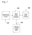
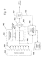
- a real-time data preprocessing module 110 carries out monitoring operations on sensor data from a monitored machine or process, and outputs transformed data to a failure mode signature recognition module 120.
- the transformed data can be alert patterns, residuals, and the like, derived from normal monitoring activities of the module 110.
- the recognition module 120 is connected to a failure mode database 140, which contains signatures of transformed data and associated failure mode information.
- a signature can comprise a plurality of residual snapshots that are known to show themselves prior to that particular failure mode, and the associated failure mode information can comprise a description of the failure mode, a likelihood, an action plan for investigating the failure mode, or a corrective plan to fix the incipient failure.
- the associated identification and any corrective actions that should be taken are output in the failure mode diagnosis and actions output module 160, which can communicate this to a display, or present the information in an object-based environment for automated action by a downstream control system or the like.
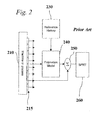
- the data preprocessing module can be any type of monitoring system, typically model-based, and more preferably empirical model-based. This is best understood with reference to FIG. 2 , which illustrates a prior art empirical model-based monitoring system, such as that described in the aforementioned patent to Gross et al. Therein is shown a machine or process 210 instrumented with sensors 215 that have data acquisition means associated with them to provide the sensor data to any number of computing systems.
- a reference library 230 of data characterizing the known or recognized states of operation of the machine or process is provided.
- the reference library 230 can reside in chip memory, or can be stored on a computer disk storage device.
- An estimation model 240 is implemented preferably in a computer as software, and receives sensor data from sensors 215 via a network or a data acquisition board.
- the estimation model 240 generates estimates of the sensor values in response to receiving the real-time values from sensors 215, using the reference library 230, as described in greater detail below.
- a differencing unit 250 receives both the estimates of the sensor values and the actual values and generates a residual for each sensor. Over successive snapshots, these residuals comprise residual signals that, as described above, should remain in the vicinity of zero with the exception of sensor and process noise, if the machine or process is operating normally (as characterized in the reference library data).
- a SPRT module 260 receives the residuals and generates alerts if the residuals show definitive evidence of being other than zero. Therefore, the outputs of this prior art system include residual signals and SPRT alerts (which are really indications of difference), and one of each is provided for each sensor on the machine or process that is monitored.
- the vertical axis 310 is a composite axis for the six sensor signals shown, and represents the signal amplitude.
- Axis 320 is the time axis.
- the sensor signals in virtually all current industrial settings are sampled digitally, and are thus a sequence of discrete values, and a "snapshot" 330 can be made at a point in time, which really represents a set of values 340 for each of the six sensors, each value representing the sensor amplitude at that time.
- a time delay between cause and effect among sensors measuring physically correlated parameters of the process and a time adjustment can be added to the data such that the snapshot 330 represents time-correlated, but not necessarily simultaneous, readings.
- An empirical model-based monitoring system for use in the present diagnostic invention requires historic data from which to "learn" normal states of operation, in order to generate sensor estimates. Generally, a large amount of data is accumulated from an instrumented machine or process running normally and through all its acceptable dynamic ranges.
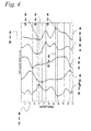
- a method for selecting training set snapshots is graphically depicted in FIG. 4 , for distilling the collected sensor data to create a representative training data set. In this simple example, five sensor signals 402, 404, 406, 408 and 410 are shown for a process or machine to be monitored. Although the sensor signals 402, 404, 406, 408 and 410 are shown as continuous, typically, these are discretely sampled values taken at each snapshot.
- snapshots need not be ordered in any particular order and so, may be ordered in chronological order, parametric ascending or descending order or in any other selected order.
- the abscissa axis 412 is the sample number or time stamp of the collected sensor data, where the data is digitally sampled and the sensor data is temporally correlated.
- the ordinate axis 414 represents the relative magnitude of each sensor reading over the samples or "snapshots.”
- each snapshot represents a vector of five element, one reading for each sensor in that snapshot.
- the global maximum 416 for sensor 402 justifies the inclusion of the five sensor values at the intersections of line 418 with each sensor signal 402, 404, 406, 408, 410, including global maximum 416, in the representative training set, as a vector of five elements.
- the global minimum 420 for sensor 402 justifies the inclusion of the five sensor values at the intersections of line 422 with each sensor signal 402, 404, 406, 408, 410.
- Collections of such snapshots represent states the system has taken on.
- the pre-collected sensor data is filtered to produce a "training" subset that reflects all states that the system takes on while operating "normally” or “acceptably” or “preferably.”
- This training set forms a matrix, having as many rows as there are sensors of interest, and as many columns (snapshots) as necessary to capture all the acceptable states without redundancy.
- Data collected in Step 500 has N sensors and L observations or snapshots or temporally related sets of sensor data that comprise Array X of N rows and L column.
- counter i (representing the element or sensor number) is initialized to zero
- observation or snapshot counter, t is initialized to one.
- Arrays max and min (containing maximum and minimum values, respectively, across the collected data for each sensor) are initialized to be vectors each of N elements which are set equal to the first column of X.
- Additional Arrays Tmax and Tmin are initialized to be vectors each of N elements, all zero.
- Step 510 if the sensor value of sensor i at snapshot t in X is greater than the maximum yet seen for that sensor in the collected data, max(i) is updated and set to equal the sensor value, while Tmax(i) stores the number t of the observation, as shown in Step 515. If the sensor value is not greater than the maximum, a similar test is done for the minimum for that sensor, as illustrated in Steps 520 and 525. The observation counter t is then incremented in Step 530. As shown in Step 535, if all the observations have been reviewed for a given sensor (i.e., when the observation counter t equals the number of snapshots, L) then the observation counter t is reset to one and the counter i is incremented, as shown in Step 540.
- Step 550 counter and j are both initialized to one.
- arrays Tmax and Tmin are concatenated to form a single vector Ttmp.
- Ttmp has 2N elements, sorted into ascending (or descending) order, as shown in Step 560 to form Array T.
- holder tmp is set to the first value in T (an observation number that contains a sensor minimum or maximum).
- the first column of Array D is set to be equal to the column of Array X corresponding to the observation number that is the first element of T.
- the ith element of T is compared to the value of tmp that contains the previous element of T.
- Step 575 If they are equal (i.e., the corresponding observation vector is a minimum or maximum for more than one sensor), that vector has already been included in Array D and need not be included again.
- Counter i is then incremented, as shown in Step 575. If the comparison is not equal, Array D is updated to include the column from X that corresponds to the observation number of T(i), as shown in Step 580, and tmp is updated with the value at T(i).
- Counter j is then incremented, as shown in Step 585, in addition to counter i (Step 575). In Step 590, if all the elements of T have been checked, and counter i equals twice the number of elements, N, then the distillation into training set or Array D has finished.
- Signal data may be gathered from any machine, process or living system that is monitored with sensors.
- the number of sensors used is not a limiting factor, generally, other than concerning computational overhead.
- the methods described herein are highly scalable. However, the sensors should capture at least some of the primary "drivers" of the underlying system. Furthermore, all sensors inputted to the underlying system should be interrelated in some fashion (i.e., non-linear or linear).
- the signal data appear as vectors, with as many elements as there are sensors.
- a given vector represents a "snapshot" of the underlying system at a particular moment in time. Additional processing may be done if it is necessary to insert a "delay" between the cause and effect nature of consecutive sensors. That is, if sensor A detects a change that will be monitored by sensor B three "snapshots" later, the vectors can be reorganized such that a given snapshot contains a reading for sensor A at a first moment, and a reading for sensor B three moments later.
- each snapshot can be thought of as a "state" of the underlying system.
- collections of such snapshots preferably represent a plurality of states of the system.
- any previously collected sensor data is filtered to produce a "training" subset (the reference set D) that characterizes all states that the system takes on while operating "normally” or “acceptably” or “preferably.”
- This training set forms a matrix, having as many rows as there are sensors of interest, and as many columns (snapshots) as necessary to capture the acceptable states without redundancy.
- the multiplication operation is the standard matrix/vector multiplication operator.
- the vector Y has as many elements as there are sensors of interest in the monitored process or machine.
- W has as many elements as there are reference snapshots in D.
- T superscript denotes transpose of the matrix
- Y in is the current snapshot of actual, real-time sensor data.
- the improved similarity operator of the present invention is symbolized in Equation 3, above, as the circle with the "X" disposed therein.
- D is again the reference library as a matrix
- D T represents the standard transpose of that matrix (i.e., rows become columns).
- Y in is the real-time or actual sensor values from the underlying system, and therefore is a vector snapshot.
- the symbol ⁇ represents the "similarity" operator, and can be chosen from a wide variety of operators for use in the present invention.
- the similarity operation used in the present invention should provide a quantified measure of likeness or difference between two state vectors, and more preferably yields a number that approaches one (1) with increasing sameness, and approaches zero (0) with decreasing sameness.
- this symbol should not to be confused with the normal meaning of designation of ⁇ , which is something else.
- the meaning of ⁇ is that of a "similarity" operation.
- the similarity operator, ⁇ works much as regular matrix multiplication operations, on a row-to-column basis.
- the similarity operation yields a scalar value for each pair of corresponding n th elements of a row and a column, and an overall similarity value for the comparison of the row to the column as a whole. This is performed over all row-to-column combinations for two matrices (as in the similarity operation on D and its transpose above).
- one similarity operator that can be used compares the two vectors (the i th row and j th column) on an element-by-element basis. Only corresponding elements are compared, e.g., element (i,m) with element (m,j) but not element (i,m) with element (n,j). For each such comparison, the similarity is equal to the absolute value of the smaller of the two values divided by the larger of the two values.
- the similarity is equal to one, and if the values are grossly unequal, the similarity approaches zero.
- the overall similarity of the two vectors is equal to the average of the elemental similarities.
- a different statistical combination of the elemental similarities can also be used in place of averaging, e.g., median.
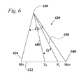
- a similarity operator that can be used can be understood with reference to FIG. 6 .
- the teachings of United States Patent No. 5,987,399 to Wegerich et al . are relevant .
- a triangle 620 is formed to determine the similarity between two values for that sensor or parameter.
- the base 622 of the triangle is set to a length equal to the difference between the minimum value 634 observed for that sensor in the entire training set, and the maximum value 640 observed for that sensor across the entire training set.
- An angle ⁇ is formed above that base 622 to create the triangle 620.
- Line segments 658 and 660 drawn to the locations of X 0 and X 1 on the base 622 form an angle ⁇ .
- the ratio of angle ⁇ to angle ⁇ gives a measure of the difference between X 0 and X 1 over the range of values in the training set for the sensor in question. Subtracting this ratio, or some algorithmically modified version of it, from the value of one yields a number between zero and one that is the measure of the similarity of X 0 and X 1 .
- Yet another example of a similarity operator determines an elemental similarity between two corresponding elements of two observation vectors or snapshots, by subtracting from one a quantity with the absolute difference of the two elements in the numerator, and the expected range for the elements in the denominator.
- the expected range can be determined, for example, by the difference of the maximum and minimum values for that element to be found across all the reference library data.
- the vector similarity is then determined by averaging the elemental similarities.
- the vector similarity of two observation vectors is equal to the inverse of the quantity of one plus the magnitude Euclidean distance between the two vectors in n-dimensional space, where n is the number of elements in each observation.
- Elemental similarities are calculated for each corresponding pairs of elements of the two snapshots being compared. Then, the elemental similarities are combined in some statistical fashion to generate a single similarity scalar value for the vector-to-vector comparison.
- Similarity operators are known or may become known to those skilled in the art, and can be employed in the present invention as described herein. The recitation of the above operators is exemplary and not meant to limit the scope of the claimed invention.
- the similarity operator is used in this invention as described below for calculation of similarity values between snapshots of residuals and the diagnostic library of residual snapshots that belie an incipient failure mode, and it should be understood that the description above of the similarity operation likewise applies to the failure mode signature recognition using residuals.
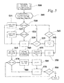
- Matrix D is provided in step 702, along with the input snapshot vector y in and an array A for computations.
- a counter i is initialized to one in step 704, and is used to count the number of observations in the training matrix D.
- another counter k is initialized to one (used to count through the number of sensors in a snapshot and observations), and array A is initialized to contain zeroes for elements.
- step 708 the element-to-element similarity operation is performed between the kth element of y in and the ( ith , kth ) element in D. These elements are corresponding sensor values, one from actual input, and one from an observation in the training history D.
- the similarity operation returns a measure of similarity of the two values, usually a value between zero (no similarity) and one (identical) which is assigned to the temporary variable r .
- step 710 r divided by the number of sensors M is added to the ith value in the one-dimensional array A.
- the ith element in A holds the average similarity for the elemental similarities of y in to the ith observation in D.
- counter k is incremented.
- step 714 if all the sensors in a particular observation in D have been compared to corresponding elements of y in , then k will now be greater than M, and i can be incremented in step 716. If not, then the next element in y in is compared for similarity to its corresponding element in D.
- step 718 a test is made in step 718 whether this is the last of the observations in D. If so, then counter i is now more than the number of observations N in D, and processing moves to step 720. Otherwise, it moves back to step 706, where the array A is reset to zeroes, and the element (sensor) counter k is reset to one.
- step 720 a weight vector W-carrot is computed from the equation shown therein, where ⁇ represents a similarity operation, typically the same similarity operator as is used in step 708.
- step 722 W-carrot is normalized using a sum of all the weight elements in W-carrot, which ameliorates the effects in subsequent steps of any particularly large elements in W-carrot, producing normalized weight vector W.
- step 724 this is used to produce the estimated output y out using D.
- FIGS. 8A-8D Examples of various preprocessed data that can be used for diagnostics as a consequence of monitoring the process or machine as described in detail herein are shown in connection with FIGS. 8A-8D.
- FIG. 8A shows both the actual signal and the estimated signal for a given sensor, one of potentially many sensors that are monitored, modeled and estimated in the estimation model 240 from FIG. 2 .
- FIG. 8B shows the resulting residual signal from differencing the signals in FIG. 8A , as is done in the differencing module 250 of FIG. 2 .
- the sensor residual takes on a series of non-zero values that lead to the eventual failure.
- the series of values taken on may be different, such that the residuals for all the sensors in the monitored system contain information for differentiating the onset of one kind of failure from another, which is essentially a first step in diagnostics.
- the alert index of FIG. 8C and the alert decisions of FIG. 8D are discussed below, but also provide information that can be used to diagnose an impending failure.
- each asterisk on the bottom line 810 indicates a decision for a given input snapshot that for this sensor, the actual and the estimated value are the same.
- Asterisks on the top line 820 indicate a point in the series of snapshots for which the estimate for this sensor and the actual appear to have diverged.
- One decision technique that can be used according to the present invention to determine whether or not to alert on a given sensor estimate is to employ thresholds for the residual for that sensor.
- Thresholds as used in the prior art are typically used on the gross value of a sensor, and therefore must be set sufficiently wide or high to avoid alerting as the measured parameter moves through its normal dynamic range.
- a residual threshold is vastly more sensitive and accurate, and is made possible by the use of the sensor value estimate. Since the residual is the difference between the actual observed sensor value and the estimate of that value based on the values of other sensors in the system (using an empirical model like the similarity engine described herein), the residual threshold is set around the expected zero-mean residual, and at a level potentially significantly narrower than the dynamic range of the parameter measured by that sensor.
- residual thresholds can be set separately for each sensor.
- the residual thresholds can be determined and fixed prior to entering real-time monitoring mode.
- a typical residual threshold can be set as a multiple of the empirically determined variance or standard deviation of the residual itself.
- the threshold for a given residual signal can be set at two times the standard deviation determined for the residual over a window of residual data generated for normal operation.
- the threshold can be determined "on-the-fly" for each residual, based on a multiplier of the variance or standard deviation determined from a moving window of a selected number of prior samples.
- the threshold applied instantly to a given residual can be two times the standard deviation determined from the past hundred residual data values.
- SPRT sequential probability ratio test
- the basic approach of the SPRT technique is to analyze successive observations of a sampled parameter.
- a sequence of sampled differences between the estimate and the actual for a monitored parameter should be distributed according to some kind of distribution function around a mean of zero. Typically, this will be a Gaussian distribution, but it may be a different distribution, as for example a binomial distribution for a parameter that takes on only two discrete values (this can be common in telecommunications and networking machines and processes).
- a test statistic is calculated and compared to one or more decision limits or thresholds.
- This general SPRT test ratio can be compared to a decision threshold to reach a decision with any observation. For example, if the outcome is greater than 0.80, then decide H 1 is the case, if less than 0.20 then decide H 0 is the case, and if in between then make no decision.
- the SPRT test can be applied to various statistical measures of the respective distributions.
- a first SPRT test can be applied to the mean and a second SPRT test can be applied to the variance.
- a positive mean test involves the ratio of the likelihood that a sequence of values belongs to a distribution H 0 around zero, versus belonging to a distribution H 1 around a positive value, typically the one standard deviation above zero.
- the negative mean test is similar, except H 1 is around zero minus one standard deviation.
- the variance SPRT test can be to test whether the sequence of values belongs to a first distribution H 0 having a known variance, or a second distribution H 2 having a variance equal to a multiple of the known variance.
- the mean is zero, and the variance can be determined. Then in run-time monitoring mode, for the mean SPRT test, the likelihood that H 0 is true (mean is zero and variance is ⁇ 2 ) is given by: L y 1 , y 2 , ... , y n
- FIG. 9 depicted in FIG. 9 is the embodiment 902 showing the three alternative avenues 906, 910 and 914 for monitoring data to be passed to the failure signature recognition module 916 (dashed lines) for failure mode recognition.
- a machine or process of interest 918 instrumented with multiple sensors 920.
- the sensor data is passed (preferably in real time) to a model 922 (preferably empirical, with a reference library or training set 923) and also to a differencing module 924.
- the model 922 generates estimates that are compared to the actual sensor values in the differencing module 924 to generate residuals, which are passed to an alert test 927.
- the alert test 927 can be the SPRT, or can be residual threshold alerts as described above, or any other alert technique based on the residual. Alerts are generated on detection of deviations from normal, as described above. Alerts may optionally be output from the system in addition to any diagnostic information.
- Avenue 906 shows that actual sensor snapshots can be passed to the failure signature recognition module 916, such that the module 916 compares the actual snapshots to stored snapshots in the failure mode database 930, and upon sufficient match (as described below) the failure mode is output corresponding to that belied by the actual sensor snapshots.
- Avenue 910 represents the alternative embodiment, where residual snapshots (comprising usually near-zero values for each of the monitored sensors) are passed to the module 916, and are compared to stored snapshots of residuals that are known to precede recognized failure modes, and upon a match (as described below), the corresponding failure mode is output.
- avenue 914 provides for feeding test alerts, more particularly SPRT alerts or residual threshold alerts from the test 927 to the module 916, which compares these, or a sequence of these over time, to SPRT or residual threshold alert patterns (as described below) stored in the database 930, and upon a match outputs the corresponding failure mode.
- the output of the failure mode can be a display or notification of one or more likely failure modes, investigative action suggestions, and resolution action suggestions, which are all stored in the database with the related failure mode signature.
- the inventive system also provides for the addition of new failure modes based on actual snapshots, residual snapshots, or alert patterns, by the user in the event none of the failure modes in the database 930 sufficiently match the precursor data to the failure.
- three sources of data can be recognized for failure signatures are presented: 1) Actual sensor data coming from the machine or process of interest; 2) residual data coming from the differencing module; and 3) SPRT or alert test patterns.
- a similarity engine may be employed for failure mode signature recognition (regardless of whether a similarity engine is used to do the initial modeling and estimate generation) that operates on either residual or actual signals using the database 140 to identify likely failure modes for automatic feedback control with associated probabilities of the failure modes.
- the signature recognition module 140 may be provided with historic data (actuals or residuals) of signatures leading up to historic failures of known mode. Failure mode recognition can execute in parallel with ongoing regular operation of the traditional similarity operator monitoring technology.
- FIG. 10 an implementation method is shown for populating the failure mode database 930 of FIG. 9 (or database 140 of FIG. 1 ) with precursor data for signature matching, and associated probabilities and action suggestions, for application of the present invention to a production run of identical machines that are designed to have on-board self-diagnostic capabilities.
- An example of such a machine may be an instrumented electric motor.
- step 1010 a plurality of the identical machines are instrumented with sensors as they would be in the field. These machines will be run to failure and ruined, in order to discover the various modes of failure of the machine design. Therefore, a sufficiently large number should be used to provide some statistical measure of the likelihood of each failure mode and to provide sufficient representative precursor data for each failure mode.
- step 1015 data collection is performed as the instrumented machines are run through routine operational ranges.
- step 1020 at least some of the data (preferably from early operation of the machine, before they begin to degrade) is captured for use in building the reference library for the empirical model, if that method of monitoring is to be used.
- step 923 the machines are all run to failure, and data is captured from the sensors as they fail.
- the captured data is processed to isolate precursor data for each failure mode.
- Failure modes are selected by the user of the invention, and are logical groupings of the specific findings from autopsies of each machine failure.
- the logical groupings of autopsied results into "modes" of failure should be sensible, and should comport with the likelihood that the precursor data leading to that failure mode will be the same or similar each time. However, beyond this requirement, the user is free to group them as seen fit.
- a manufacturer of an electric motor may choose to run 50 motors to failure, and upon autopsy, group the results into three major failure modes, related to stator problems, mechanical rotating pieces, and insulation winding breakdown. If these account for a substantial majority of the failure modes of the motor, the manufacturer may choose not to recognize other failure modes, and will accept SPRT or residual threshold alerts from monitoring with no accompanying failure mode recognition as essentially a recognition of some uncommon failure.
- commonly available analysis methods known to those in the art may be used to self-organize the precursor data for each instance of failure into logical groupings according to how similar the precursor data streams are. For example, if the user divines a distinct autopsy result for each of 50 failed motors, but analysis of the alerts shows that 45 of the failures clearly have one of three distinct alert patterns leading to failure (for example 12 failures in one pattern, 19 in another pattern and 14 in the third pattern, with the remaining 5 of the 50 belonging to and defining no recognized pattern), the three distinct patterns may be treated as failure modes. The user then must decide in what way the autopsy results match the failed modes, and what investigative and resolution actions can be suggested for the groups based thereon, and stored with the failure mode signature information.
- the normal data of 1020 should be trained and distilled down to a reference library and used offline to generate estimates, residuals and alerts in response to input of the precursor data streams.
- step 1042 the diagnostic precursor signatures, the user input regarding failure mode groupings of those signatures and suggested actions, and the empirical model reference library (if an empirical model will be used) is loaded into the onboard memory store of a computing device accompanying each machine of the production run.
- the empirical model reference library if an empirical model will be used
- FIG. 11 it may be desirable or necessary to begin with an empty failure mode database, and an implementation method for this is shown.
- an industrial process having sensors and to be retrofitted with the diagnostic system of the invention, it may not be feasible to cause the process to run to failure multiple times in order to collect precursor data and failure mode information.
- step 1153 the process is instrumented with sensors, if they are not already in place.
- step 1157 sensor data is collected as before, and the process is operated normally.
- collected data is used to train a reference library for empirical modeling.
- step 1165 the resulting reference library is loaded into the monitoring system, and in step 1170 the process is monitored in real time.
- the failure or prevented failure is autopsied in step 1176.
- step 1180 collected data (from a historian or other recording feature for operational data archiving) preceding the failure is retrieved and analyzed (as described below) in step 1183 to provide precursor residuals, alerts or actuals of the failure mode.
- the process operator is also prompted for failure mode information, and associated action suggestions to be stored in the failure mode database.
- diagnostic monitoring data on failures is collected and stored in the failure mode database, and becomes better and better with continued monitoring of the process.
- the user designates the existence, type, and time stamp of a failure.
- the designation that a process or machine has failed is subject to the criteria of the user in any case.
- a failure may be deemed to have occurred at a first time for a user having stringent performance requirements, and may be deemed to have occurred at a later second time for a user willing to expend the machine or process machinery.
- the designation of a failure may also be accomplished using an automated system. For example, a gross threshold applied to the actual sensor signal as is known in the art, may be used to designate the time of a failure.
- the alerts of the present invention can also be thresholded or compared to some baseline in order to determine a failure.
- the failure time stamp is provided by the user, or by a separate automatic system monitoring a parameter against a failure threshold.
- the residual snapshot similarity discussed herein provides for a library of prior residual snapshots, i.e., the difference signals obtained preceding identified failure modes which may be compared using the above-described similarity engine and equation 4 with a current residual snapshot to determine the development of a know failure mode.
- the residual snapshots are identified and stored as precursors to known failure modes.
- Various criteria may be employed for selecting snapshots representative of the failure mode residuals for use in the library and for determining the defining characteristics of the failure modes, and criteria for determination of the failure modes.
- the actual snapshot similarity used for diagnosis is performed in a manner identical with the residual snapshot similarity. Instead of using residual snapshots, actual snapshots are used as precursor data. Then actual snapshots are compared to the failure mode database of precursor actuals and similarities between them indicate incipient failure modes, as described in further detail below.
- the alert module output will represent decisions for each monitored sensor decomposed input, as to whether the estimate for it is different or the same. These can in turn be used for diagnosis of the state of the process or equipment being monitored. The occurrence of some difference decisions (alerts on a sensor) in conjunction with other sameness decisions (no alerts on a sensor) can be used as an indicator of likely machine or process states.
- a diagnostic lookup database can be indexed into by means of the alert decisions to diagnose the condition of the process or equipment being monitored with the inventive system.
- a particular failure mode is evidenced by alerts appearing at first on sensors #1 and #3, compounded after some generally bounded time by alerts appearing on sensor #4 additionally, then the occurrence of this pattern can be matched to the stored pattern and the failure mode identified.
- One means for matching the failure modes according to developing sensor alert patterns such as these is the use of Bayesian Belief Networks, which are known to those skilled in the art for use in quantifying the propagation of probabilities through a certain chain of events.
- the matching can be done merely by examining how many alerting sensors correspond to sensor alerts in the database, and outputting the best matches as identified failure mode possibilities.
- the alerts can be treated as a two-dimensional array of pixels, and the pattern analyzed for likeness to stored patterns using character recognition techniques known in the art.
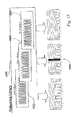
- FIGS. 12A, 12B and 12C several methods are shown for automatically selecting how far prior to a user-designated conventional failure point to go back when incorporating failure mode precursor snapshots into a library for purposes of the residual signature approach and the straight-data signature approach. Shown are the plots for a sensor and model estimate (fin . 12A), residual (12B) and SPRT alerts (12C).
- the conventional point of failure as it would be understood in the prior art methods is shown in FIGS. 12A and 12B as line 1207 and 1209 respectively.
- the number of snapshots prior to a designated failure to include in "training" or distillation to a representative set that will form a failure mode library for either residual snapshot similarity or actual snapshot similarity can be determined as a fixed number selected by the user, either globally for all failures and failure modes, or specific to each autopsied failure. In other words, the user simply dictates based on his knowledge of the sampling rate of the monitoring of the process or machine, that snapshots are included up to, say, 120 prior to the time of failure. This then determines a range 1224 of residual snapshots (or actual snapshots) that are to be distilled.
- the location in FIG. 12C of line 1220 is used to determine the snapshot earliest snapshot in the set 1224.
- Line 1220 is determined as the earliest consistent SPRT or residual threshold-alerted snapshot, where "consistent" means that at least a selected number of snapshots in a moving window are alerted for at least a selected number of sensors.
- Consistent means that at least a selected number of snapshots in a moving window are alerted for at least a selected number of sensors.
- the beginning (or end) of that window demarks the beginning of range 1224.
- the range to extend over for failure mode precursor selection extends back to T, not T-50.
- the range 1224 of residual or actual snapshots, each snapshot comprising a residual value or actual value for each sensor, is then distilled to a representative set for the identified failure mode.
- This distillation process is essentially the same as the training method described in FIGS. 4 and 5 for developing a reference library for empirical modeling.
- the training process described in the flowchart of FIG. 5 can be used, as can other training methods known in the art or subsequently developed.
- the library can be augmented.
- One way of augmenting it is to recombine all of the precursor snapshot sets for that failure mode from all documented instances of the failure, and rerun the training process against the combination.
- Another way is to add the range of snapshots 1224 to the existing distilled library, and rerun the training process against that combination.
- This precursor data is processed to provide representative data and the associated failure mode, appropriate to the inventive technique chosen from the three prior mentioned techniques for diagnosing failures.
- This data is added to any existing data on the failure mode, and the system is set back into monitoring mode. Now, the system has more intelligence on precursor data leading up to the particular failure mode.
- the failure mode granularity is entirely user-selectable.
- the failure modes can be strictly user defined, where the user must do the autopsy and determine cause. The user must furthermore supply a name and/ or ID for the failure mode.
- the software product of the invention preferably provides an empty data structure for storing:
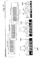
- the failure mode precursor reference library 1305 that is included in the failure mode database 140 from FIG. 1 can be seen to comprise groups of snapshots 1312, 1315 and 1317 that represent the precursor snapshots (either actual or residual) that are associated with the failure modes A, B and C respectively.
- a sequence 1320 of successive current input snapshots (either actual or residual, depending on the implemented embodiment), depicted as vectors with dots as placeholders for parameter values, is fed into a failure mode similarity engine 1324 (comprising the failure mode signature recognition module 120 from FIG. 1 ), disposed to calculate snapshot-to-snapshot similarities as described above with respect to the similarity operators used for modeling and equation 4.
- the snapshots of sequence 1320 all have an identical number of parameters, as do the snapshots in the library 1305.
- the engine 1324 does not carry out equation 1 above, and thus does not output estimates of any kind, but instead outputs the snapshot similarity scores of each current snapshot as compared to each stored snapshot for at least some and preferably all modes in the library 1305.
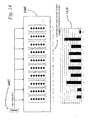
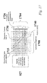
- the failure mode similarity engine 1324 of FIG. 13 can better be understood in view of FIG. 14 , wherein is shown the results for a comparison of a single snapshot 1407 of either actual data from sensors or residual data from the difference of the actual and estimated data for sensors, when compared using the similarity operator to the failure mode precursors in the library 1305.
- Each snapshot-to-snapshot comparison results in a similarity value, which are charted in chart 1415.
- Reference library 1305 contains failure mode signature data (either residual snapshots or actual snapshots) for several failure modes 1312,1315 and 1317.
- a current snapshot is compared using the similarity operation to generate similarity scores for each comparison to reference library snapshots.
- the failure mode with a single-snapshot similarity 1550 that is highest across all such comparisons in the reference library is designated as the indicated failure mode.
- FIG. 15 In another way of selecting the indicated failure mode, as shown in FIG.
- the average of all the snapshot similarities for all snapshots in a given failure mode is computed, and the averages 1620,1630 and 1640 for each failure mode are compared.
- the failure mode 1650 with the highest average similarity is designated as the indicated failure mode for the current snapshot. Either way of designating an indicated failure mode for a given current snapshot, as shown in FIGS. 15 and 16 , can be combined with a number of alternative ways of selecting the indicated failure mode over successive snapshots. Accordingly, no failure mode may be displayed to the user based on just one snapshot, but a moving window of snapshots over which a count of elected failure modes according to FIGS.
- the method of electing the failure mode with the highest average similarity may be used for each current snapshot, and a moving window of twenty (20) snapshots may be used, and a threshold is employed according to which a failure mode must be elected at least 10 times in that window in order for that failure mode to be indicated as an incipient failure mode to the user.
- Counts are maintained for all failure modes in the system over the twenty snapshot window, and if one of them achieves a count of greater than 10, it is indicated as an incipient failure to the user.
- Alert test 927 (from FIG. 9 ) generates alerts on signal lines 1704, at each of successive snapshots 1708, as indicated by the asterisk,
- the pattern 1715 of alerts at any given snapshot can be matched to the patterns stored for various failure modes, to determine whether or not a failure mode is indicated.
- the cumulative pattern 1720 of alerts can be matched against stored patterns, where alert accumulation occurs over a window of a selected number of snapshots.
- the pattern match for any of the above alert patterns can be selected from a number of techniques. For example, a complete match may be required, such that a match is not indicated unless each and every alert in the stored pattern is also found in the instant pattern, and no extraneous alerts are found in the instant pattern. Alternatively, a substantial match can be employed, such that at least, say, 75% of the sensors showing alerts in the stored pattern are also found alerting in the instant pattern, and no more than 10% of the instant alerts are not found in the stored pattern.
- the exact thresholds for matching and extraneous alerts can be set globally, or can be set for each stored pattern, such that one failure mode may tolerate just 65% matching and no more than 10% extraneous alerts, while a second failure mode may be indicated when at least 80% of the stored alerts are matched, and no more than 5% extraneous alerts occurring in the instant pattern are not in the stored pattern. These limits may be set empirically, as is necessary to sufficiently differentiate the failure modes that are desirably recognized, and with sufficient forewarning to provide benefit.
- FIG. 18 shows a physical embodiment 1820 for any of the inventive approaches to diagnosis disclosed herein.
- a process or machine 1822 provides sensor output to an input bus 1824.
- the process might be a process control system at a chemical processing plant, and the bus is the FieldBus-type architecture commonly used in industry.
- a processor 1826 is disposed to calculate the model estimates of the parameters in response to the input of the actual parameters from bus 1824, and further to compare the estimates to the actual sensor values and compute alert tests.
- Processor 1826 is further disposed to execute failure signature recognition, when coupled with a memory 1828 for storing program code and loaded with model and signature data. The processor can output control commands back to the process control system for corrective action in the event of a diagnosis of an impending failure.
- the processor can output the resulting diagnosis and accompanying data to a display 1832, or can also optionally send it via a transmitted 1830 to a remote location;
- the transmitter could be a web-connected device, or a wireless device, by way of example.
- the receiver (not shown) could be a pager, another data processing system at a remote location, and the like.
- the failure mode data store can be in any conventional memory device, such as a hard disk drive, nonvolatile or volatile memory, or on-chip memory.
- the data store for the empirical modeling data that is used to generate the estimates of parameters in response to actual parameter values can be separate from or the same as the data store which contains failure mode signature information.
- failure mode action suggestions can also be stored either together with or separately from the other aforementioned data. Such may be the case where the present invention comprises combing a failure mode signature recognition system with an existing maintenance operations resource planning system that automatically generates maintenance requests and schedules them.
- the computational programs for performing similarity-based residual or actual sensor snapshot failure mode signature recognition; alert pattern-based failure mode signature recognition; process modeling and sensor value estimation; residual generation from actual and estimated values; and alert testing can be carried out on one processor, or distributed as separate tasks across multiple processors that are in synchronous or asynchronous communications with one another. In this way, it is entirely within the inventive scope for the diagnostic system of the present invention to be carried out using a single microprocessor on-board a monitored machine, or using a number of separately located computers communicating over the internet and possibly remotely located from the monitored process or machine.
- the computational program that comprises the similarity engine that generates estimates in response to live data can also be the same programmed similarity engine that generates similarity scores for use in matching a residual snapshot or actual snapshot to stored snapshots associated with failure modes.
Landscapes
- Engineering & Computer Science (AREA)
- Physics & Mathematics (AREA)
- General Physics & Mathematics (AREA)
- Artificial Intelligence (AREA)
- Evolutionary Computation (AREA)
- Data Mining & Analysis (AREA)
- Automation & Control Theory (AREA)
- Mathematical Physics (AREA)
- Theoretical Computer Science (AREA)
- General Engineering & Computer Science (AREA)
- Evolutionary Biology (AREA)
- Computer Vision & Pattern Recognition (AREA)
- Bioinformatics & Computational Biology (AREA)
- Algebra (AREA)
- Mathematical Analysis (AREA)
- Mathematical Optimization (AREA)
- Bioinformatics & Cheminformatics (AREA)
- Probability & Statistics with Applications (AREA)
- Pure & Applied Mathematics (AREA)
- Life Sciences & Earth Sciences (AREA)
- Testing And Monitoring For Control Systems (AREA)
- Controlling Sheets Or Webs (AREA)
Applications Claiming Priority (2)
| Application Number | Priority Date | Filing Date | Title |
|---|---|---|---|
| US09/832,166 US20020183971A1 (en) | 2001-04-10 | 2001-04-10 | Diagnostic systems and methods for predictive condition monitoring |
| EP02714744A EP1393177A4 (fr) | 2001-04-10 | 2002-01-11 | Systemes et methodes de diagnostic pour la surveillance d'etat preventive |
Related Parent Applications (2)
| Application Number | Title | Priority Date | Filing Date |
|---|---|---|---|
| EP02714744A Division EP1393177A4 (fr) | 2001-04-10 | 2002-01-11 | Systemes et methodes de diagnostic pour la surveillance d'etat preventive |
| EP02714744.6 Division | 2002-01-11 |
Publications (3)
| Publication Number | Publication Date |
|---|---|
| EP2015186A2 true EP2015186A2 (fr) | 2009-01-14 |
| EP2015186A3 EP2015186A3 (fr) | 2010-09-22 |
| EP2015186B1 EP2015186B1 (fr) | 2013-03-13 |
Family
ID=25260872
Family Applications (2)
| Application Number | Title | Priority Date | Filing Date |
|---|---|---|---|
| EP08167804A Expired - Lifetime EP2015186B1 (fr) | 2001-04-10 | 2002-01-11 | Systèmes de diagnostic et procédés pour le contrôle de conditions prédictives |
| EP02714744A Ceased EP1393177A4 (fr) | 2001-04-10 | 2002-01-11 | Systemes et methodes de diagnostic pour la surveillance d'etat preventive |
Family Applications After (1)
| Application Number | Title | Priority Date | Filing Date |
|---|---|---|---|
| EP02714744A Ceased EP1393177A4 (fr) | 2001-04-10 | 2002-01-11 | Systemes et methodes de diagnostic pour la surveillance d'etat preventive |
Country Status (6)
| Country | Link |
|---|---|
| US (3) | US20020183971A1 (fr) |
| EP (2) | EP2015186B1 (fr) |
| JP (3) | JP2004531815A (fr) |
| AU (1) | AU2002246994B2 (fr) |
| CA (1) | CA2443579A1 (fr) |
| WO (1) | WO2002086726A1 (fr) |
Cited By (4)
| Publication number | Priority date | Publication date | Assignee | Title |
|---|---|---|---|---|
| WO2012044197A1 (fr) * | 2010-09-28 | 2012-04-05 | Закрытое Акционерное Общество "Диаконт" | Dispositif permettant de surveiller les risques et procédé de surveillance des risques, destinés à une installation énergétique atomique |
| EP3109719A1 (fr) * | 2015-06-25 | 2016-12-28 | Mitsubishi Electric R&D Centre Europe B.V. | Procédé et dispositif permettant d'estimer un niveau de détérioration d'un dispositif électrique |
| US10013814B2 (en) | 2015-03-04 | 2018-07-03 | MTU Aero Engines AG | Diagnosis of aircraft gas turbine engines |
| EP4198668A1 (fr) * | 2021-12-16 | 2023-06-21 | Commissariat à l'énergie atomique et aux énergies alternatives | Procédé et système de détection et de caractérisation de signaux faibles d'exposition à un risque dans un système industriel |
Families Citing this family (266)
| Publication number | Priority date | Publication date | Assignee | Title |
|---|---|---|---|---|
| US9056783B2 (en) | 1998-12-17 | 2015-06-16 | Hach Company | System for monitoring discharges into a waste water collection system |
| US7454295B2 (en) | 1998-12-17 | 2008-11-18 | The Watereye Corporation | Anti-terrorism water quality monitoring system |
| WO2001061615A1 (fr) * | 2000-02-14 | 2001-08-23 | Infoglide Corporation | Systeme et procede de surveillance et de commande de processus et de machines |
| US6917839B2 (en) * | 2000-06-09 | 2005-07-12 | Intellectual Assets Llc | Surveillance system and method having an operating mode partitioned fault classification model |
| US6556939B1 (en) * | 2000-11-22 | 2003-04-29 | Smartsignal Corporation | Inferential signal generator for instrumented equipment and processes |
| US7539597B2 (en) * | 2001-04-10 | 2009-05-26 | Smartsignal Corporation | Diagnostic systems and methods for predictive condition monitoring |
| US20030034995A1 (en) * | 2001-07-03 | 2003-02-20 | Osborn Brock Estel | Interactive graphics-based analysis tool for visualizing reliability of a system and performing reliability analysis thereon |
| US7085675B2 (en) * | 2002-02-06 | 2006-08-01 | The University Of Chicago | Subband domain signal validation |
| FR2836226B1 (fr) * | 2002-02-18 | 2004-05-14 | Airbus France | Procede d'identification d'une source d'un signal |
| US20030208592A1 (en) * | 2002-05-01 | 2003-11-06 | Taylor William Scott | System and method for proactive maintenance through monitoring the performance of a physical interface |
| GB0221638D0 (en) * | 2002-09-17 | 2002-10-30 | Ibm | Device system and method for predictive failure analysis |
| WO2004030172A1 (fr) * | 2002-09-26 | 2004-04-08 | Siemens Aktiengesellschaft | Procede et dispositif de surveillance d'une installation technique utilises en particulier a des fins de diagnostic |
| JP2006505856A (ja) * | 2002-11-04 | 2006-02-16 | スマートシグナル・コーポレーション | 再発性ローカル学習機械を使用するシステム状態モニタリング方法及びその装置 |
| FR2849236B1 (fr) * | 2002-12-20 | 2005-02-04 | Renault Sa | Procede de diagnostics d'un ensemble de systemes electroniques |
| US20040243636A1 (en) * | 2003-03-18 | 2004-12-02 | Smartsignal Corporation | Equipment health monitoring architecture for fleets of assets |
| US8920619B2 (en) | 2003-03-19 | 2014-12-30 | Hach Company | Carbon nanotube sensor |
| US7593936B2 (en) | 2003-08-11 | 2009-09-22 | Triumfant, Inc. | Systems and methods for automated computer support |
| EP1661047B1 (fr) * | 2003-08-11 | 2017-06-14 | Triumfant, Inc. | Systemes et procedes d'assistance informatique automatisee |
| US7234084B2 (en) | 2004-02-18 | 2007-06-19 | Emerson Process Management | System and method for associating a DLPDU received by an interface chip with a data measurement made by an external circuit |
| US7058089B2 (en) * | 2004-02-18 | 2006-06-06 | Rosemount, Inc. | System and method for maintaining a common sense of time on a network segment |
| US20050261837A1 (en) * | 2004-05-03 | 2005-11-24 | Smartsignal Corporation | Kernel-based system and method for estimation-based equipment condition monitoring |
| US20050262399A1 (en) * | 2004-05-05 | 2005-11-24 | Brown Adam C | Aggregating and prioritizing failure signatures by a parsing program |
| US11680867B2 (en) | 2004-06-14 | 2023-06-20 | Wanda Papadimitriou | Stress engineering assessment of risers and riser strings |
| US11710489B2 (en) | 2004-06-14 | 2023-07-25 | Wanda Papadimitriou | Autonomous material evaluation system and method |
| US7254491B2 (en) * | 2004-06-28 | 2007-08-07 | Honeywell International, Inc. | Clustering system and method for blade erosion detection |
| US7409314B2 (en) * | 2004-07-29 | 2008-08-05 | International Business Machines Corporation | Method for first pass filtering of anomalies and providing a base confidence level for resource usage prediction in a utility computing environment |
| US8645540B2 (en) * | 2004-07-29 | 2014-02-04 | International Business Machines Corporation | Avoiding unnecessary provisioning/deprovisioning of resources in a utility services environment |
| DE102004038835A1 (de) * | 2004-08-10 | 2006-02-23 | Siemens Ag | Verfahren zur Detektion von Störquellen oder von fehlerhaften Messsensoren durch Gutfall-Modellierung und teilweises Ausblenden von Gleichungen |
| US7216061B2 (en) * | 2004-08-25 | 2007-05-08 | Siemens Corporate Research, Inc. | Apparatus and methods for detecting system faults using hidden process drivers |
| US7188482B2 (en) * | 2004-08-27 | 2007-03-13 | Carrier Corporation | Fault diagnostics and prognostics based on distance fault classifiers |
| US7567887B2 (en) * | 2004-09-10 | 2009-07-28 | Exxonmobil Research And Engineering Company | Application of abnormal event detection technology to fluidized catalytic cracking unit |
| US20060074598A1 (en) * | 2004-09-10 | 2006-04-06 | Emigholz Kenneth F | Application of abnormal event detection technology to hydrocracking units |
| US7424395B2 (en) * | 2004-09-10 | 2008-09-09 | Exxonmobil Research And Engineering Company | Application of abnormal event detection technology to olefins recovery trains |
| US7349746B2 (en) * | 2004-09-10 | 2008-03-25 | Exxonmobil Research And Engineering Company | System and method for abnormal event detection in the operation of continuous industrial processes |
| US7173539B2 (en) * | 2004-09-30 | 2007-02-06 | Florida Power And Light Company | Condition assessment system and method |
| WO2006039760A1 (fr) * | 2004-10-15 | 2006-04-20 | Ipom Pty Ltd | Procede d'analyse de donnees |
| US7693982B2 (en) * | 2004-11-12 | 2010-04-06 | Hewlett-Packard Development Company, L.P. | Automated diagnosis and forecasting of service level objective states |
| WO2006064991A1 (fr) * | 2004-12-17 | 2006-06-22 | Korea Research Institute Of Standards And Science | Procede de diagnostic de precision pour la protection contre la defaillance et entretien predictif dune pompe a vide et systeme de diagnostic de precision correspondant |
| US7836111B1 (en) * | 2005-01-31 | 2010-11-16 | Hewlett-Packard Development Company, L.P. | Detecting change in data |
| US7505868B1 (en) * | 2005-01-31 | 2009-03-17 | Hewlett-Packard Development Company, L.P. | Performing quality determination of data |
| CN100437836C (zh) * | 2005-03-25 | 2008-11-26 | 大亚湾核电运营管理有限责任公司 | 压水堆核电站严重事故的诊断和处理方法 |
| US20060293859A1 (en) * | 2005-04-13 | 2006-12-28 | Venture Gain L.L.C. | Analysis of transcriptomic data using similarity based modeling |
| US7640145B2 (en) * | 2005-04-25 | 2009-12-29 | Smartsignal Corporation | Automated model configuration and deployment system for equipment health monitoring |
| US20060248236A1 (en) * | 2005-04-28 | 2006-11-02 | Agere Systems Inc. | Method and apparatus for time correlating defects found on hard disks |
| US7809781B1 (en) | 2005-04-29 | 2010-10-05 | Hewlett-Packard Development Company, L.P. | Determining a time point corresponding to change in data values based on fitting with respect to plural aggregate value sets |
| US7818131B2 (en) * | 2005-06-17 | 2010-10-19 | Venture Gain, L.L.C. | Non-parametric modeling apparatus and method for classification, especially of activity state |
| US7839279B2 (en) * | 2005-07-29 | 2010-11-23 | Dp Technologies, Inc. | Monitor, alert, control, and share (MACS) system |
| US7155365B1 (en) * | 2005-08-02 | 2006-12-26 | Sun Microsystems, Inc. | Optimal bandwidth and power utilization for ad hoc networks of wireless smart sensors |
| US7333917B2 (en) * | 2005-08-11 | 2008-02-19 | The University Of North Carolina At Chapel Hill | Novelty detection systems, methods and computer program products for real-time diagnostics/prognostics in complex physical systems |
| US7849184B1 (en) * | 2005-10-07 | 2010-12-07 | Dp Technologies, Inc. | Method and apparatus of monitoring the status of a sensor, monitor, or device (SMD) |
| CN102908130B (zh) * | 2005-11-29 | 2015-04-22 | 风险获利有限公司 | 用于监测人体健康状态的设备 |
| CA2570425A1 (fr) * | 2005-12-06 | 2007-06-06 | March Networks Corporation | Systeme et methode de surveillance automatique de l'etat de sante par camera |
| US7603586B1 (en) * | 2005-12-30 | 2009-10-13 | Snap-On Incorporated | Intelligent stationary power equipment and diagnostics |
| US7747735B1 (en) | 2006-02-02 | 2010-06-29 | Dp Technologies, Inc. | Method and apparatus for seamlessly acquiring data from various sensor, monitor, device (SMDs) |
| EP1818746A1 (fr) * | 2006-02-10 | 2007-08-15 | ALSTOM Technology Ltd | Procédé de surveillance de condition |
| US7558985B2 (en) * | 2006-02-13 | 2009-07-07 | Sun Microsystems, Inc. | High-efficiency time-series archival system for telemetry signals |
| US7496798B2 (en) * | 2006-02-14 | 2009-02-24 | Jaw Link | Data-centric monitoring method |
| US8864663B1 (en) | 2006-03-01 | 2014-10-21 | Dp Technologies, Inc. | System and method to evaluate physical condition of a user |
| US8725527B1 (en) | 2006-03-03 | 2014-05-13 | Dp Technologies, Inc. | Method and apparatus to present a virtual user |
| US7761172B2 (en) * | 2006-03-21 | 2010-07-20 | Exxonmobil Research And Engineering Company | Application of abnormal event detection (AED) technology to polymers |
| US7269536B1 (en) * | 2006-03-23 | 2007-09-11 | Sun Microsystems, Inc. | Method and apparatus for quantitatively determining severity of degradation in a signal |
| EP1839572A2 (fr) * | 2006-03-31 | 2007-10-03 | Casio Computer Co., Ltd. | Dispositif de mesure d'informations biologiques et système de mesure d'informations biologiques |
| US7975184B2 (en) * | 2006-04-03 | 2011-07-05 | Donald Goff | Diagnostic access system |
| US7720641B2 (en) * | 2006-04-21 | 2010-05-18 | Exxonmobil Research And Engineering Company | Application of abnormal event detection technology to delayed coking unit |
| US7841967B1 (en) | 2006-04-26 | 2010-11-30 | Dp Technologies, Inc. | Method and apparatus for providing fitness coaching using a mobile device |
| US8191099B2 (en) | 2006-04-28 | 2012-05-29 | Johnson Lee R | Automated analysis of collected field data for error detection |
| US7890813B2 (en) * | 2006-05-11 | 2011-02-15 | Oracle America, Inc. | Method and apparatus for identifying a failure mechanism for a component in a computer system |
| US8902154B1 (en) | 2006-07-11 | 2014-12-02 | Dp Technologies, Inc. | Method and apparatus for utilizing motion user interface |
| US20080097945A1 (en) * | 2006-08-09 | 2008-04-24 | The University Of North Carolina At Chapel Hill | Novelty detection systems, methods and computer program products for real-time diagnostics/prognostics in complex physical systems |
| US8341260B2 (en) | 2006-08-16 | 2012-12-25 | Oracle America, Inc. | Method and system for identification of decisive action state of server components via telemetric condition tracking |
| US8275577B2 (en) * | 2006-09-19 | 2012-09-25 | Smartsignal Corporation | Kernel-based method for detecting boiler tube leaks |
| US7707285B2 (en) * | 2006-09-27 | 2010-04-27 | Integrien Corporation | System and method for generating and using fingerprints for integrity management |
| US20080109862A1 (en) * | 2006-11-07 | 2008-05-08 | General Instrument Corporation | Method and apparatus for predicting failures in set-top boxes and other devices to enable preventative steps to be taken to prevent service disruption |
| US8311774B2 (en) | 2006-12-15 | 2012-11-13 | Smartsignal Corporation | Robust distance measures for on-line monitoring |
| US8620353B1 (en) | 2007-01-26 | 2013-12-31 | Dp Technologies, Inc. | Automatic sharing and publication of multimedia from a mobile device |
| US9047359B2 (en) * | 2007-02-01 | 2015-06-02 | Hand Held Products, Inc. | Apparatus and methods for monitoring one or more portable data terminals |
| US8949070B1 (en) | 2007-02-08 | 2015-02-03 | Dp Technologies, Inc. | Human activity monitoring device with activity identification |
| US8612029B2 (en) * | 2007-06-15 | 2013-12-17 | Shell Oil Company | Framework and method for monitoring equipment |
| US8555282B1 (en) | 2007-07-27 | 2013-10-08 | Dp Technologies, Inc. | Optimizing preemptive operating system with motion sensing |
| KR101491196B1 (ko) | 2007-08-03 | 2015-02-06 | 스마트시그널 코포레이션 | 결함 패턴 매칭을 위한 퍼지 분류 접근 |
| US20090056949A1 (en) * | 2007-08-27 | 2009-03-05 | Mcstay Daniel | Fluorescence measurement system for detecting leaks from subsea systems and structures |
| US7918126B2 (en) * | 2007-09-26 | 2011-04-05 | Fmc Technologies, Inc. | Intelligent underwater leak detection system |
| US8005771B2 (en) * | 2007-10-04 | 2011-08-23 | Siemens Corporation | Segment-based change detection method in multivariate data stream |
| US8271417B2 (en) | 2007-10-19 | 2012-09-18 | Oracle International Corporation | Health meter |
| US20100153146A1 (en) * | 2008-12-11 | 2010-06-17 | International Business Machines Corporation | Generating Generalized Risk Cohorts |
| US8949671B2 (en) * | 2008-01-30 | 2015-02-03 | International Business Machines Corporation | Fault detection, diagnosis, and prevention for complex computing systems |
| US8320578B2 (en) * | 2008-04-30 | 2012-11-27 | Dp Technologies, Inc. | Headset |
| DE102008022459A1 (de) * | 2008-05-08 | 2009-11-12 | Mtu Aero Engines Gmbh | Vorrichtung und Verfahren zur Überwachung einer Gasturbine |
| US7967066B2 (en) * | 2008-05-09 | 2011-06-28 | Fmc Technologies, Inc. | Method and apparatus for Christmas tree condition monitoring |
| US8285344B2 (en) | 2008-05-21 | 2012-10-09 | DP Technlogies, Inc. | Method and apparatus for adjusting audio for a user environment |
| US8352216B2 (en) * | 2008-05-29 | 2013-01-08 | General Electric Company | System and method for advanced condition monitoring of an asset system |
| US8230269B2 (en) | 2008-06-17 | 2012-07-24 | Microsoft Corporation | Monitoring data categorization and module-based health correlations |
| US8996332B2 (en) | 2008-06-24 | 2015-03-31 | Dp Technologies, Inc. | Program setting adjustments based on activity identification |
| US8849630B2 (en) * | 2008-06-26 | 2014-09-30 | International Business Machines Corporation | Techniques to predict three-dimensional thermal distributions in real-time |
| AT507019B1 (de) * | 2008-07-04 | 2011-03-15 | Siemens Vai Metals Tech Gmbh | Verfahren zur überwachung einer industrieanlage |
| US20100013654A1 (en) * | 2008-07-16 | 2010-01-21 | Williams Bruce A | Self-contained monitoring and remote testing device and method |
| US8631117B2 (en) * | 2008-08-19 | 2014-01-14 | Vmware, Inc. | System and method for correlating fingerprints for automated intelligence |
| US7845404B2 (en) * | 2008-09-04 | 2010-12-07 | Fmc Technologies, Inc. | Optical sensing system for wellhead equipment |
| US8375249B1 (en) * | 2008-09-19 | 2013-02-12 | Emc Corporation | Method for testing battery backup units |
| US8872646B2 (en) | 2008-10-08 | 2014-10-28 | Dp Technologies, Inc. | Method and system for waking up a device due to motion |
| US8301443B2 (en) | 2008-11-21 | 2012-10-30 | International Business Machines Corporation | Identifying and generating audio cohorts based on audio data input |
| US8041516B2 (en) * | 2008-11-24 | 2011-10-18 | International Business Machines Corporation | Identifying and generating olfactory cohorts based on olfactory sensor input |
| IT1392258B1 (it) * | 2008-12-05 | 2012-02-22 | Alenia Aeronautica Spa | Procedimento per la prognostica di una struttura sottoposta a carichi. |
| US8749570B2 (en) * | 2008-12-11 | 2014-06-10 | International Business Machines Corporation | Identifying and generating color and texture video cohorts based on video input |
| US20100153147A1 (en) * | 2008-12-12 | 2010-06-17 | International Business Machines Corporation | Generating Specific Risk Cohorts |
| US8190544B2 (en) | 2008-12-12 | 2012-05-29 | International Business Machines Corporation | Identifying and generating biometric cohorts based on biometric sensor input |
| US8417035B2 (en) * | 2008-12-12 | 2013-04-09 | International Business Machines Corporation | Generating cohorts based on attributes of objects identified using video input |
| US20100153174A1 (en) * | 2008-12-12 | 2010-06-17 | International Business Machines Corporation | Generating Retail Cohorts From Retail Data |
| US20100153597A1 (en) * | 2008-12-15 | 2010-06-17 | International Business Machines Corporation | Generating Furtive Glance Cohorts from Video Data |
| US8271834B2 (en) * | 2008-12-15 | 2012-09-18 | International Business Machines Corporation | Method and system for providing immunity to computers |
| US8493216B2 (en) * | 2008-12-16 | 2013-07-23 | International Business Machines Corporation | Generating deportment and comportment cohorts |
| US8219554B2 (en) * | 2008-12-16 | 2012-07-10 | International Business Machines Corporation | Generating receptivity scores for cohorts |
| US11145393B2 (en) | 2008-12-16 | 2021-10-12 | International Business Machines Corporation | Controlling equipment in a patient care facility based on never-event cohorts from patient care data |
| US20100153133A1 (en) * | 2008-12-16 | 2010-06-17 | International Business Machines Corporation | Generating Never-Event Cohorts from Patient Care Data |
| US20100153180A1 (en) * | 2008-12-16 | 2010-06-17 | International Business Machines Corporation | Generating Receptivity Cohorts |
| US8700260B2 (en) | 2009-03-30 | 2014-04-15 | Lord Corporation | Land vehicles and systems with controllable suspension systems |
| JP5290026B2 (ja) * | 2009-03-31 | 2013-09-18 | 日立建機株式会社 | 作業機械の学習診断システム、状態診断装置及び状態学習装置 |
| JP5244686B2 (ja) | 2009-04-24 | 2013-07-24 | 株式会社東芝 | 監視装置およびサーバー |
| US9529437B2 (en) | 2009-05-26 | 2016-12-27 | Dp Technologies, Inc. | Method and apparatus for a motion state aware device |
| US8171343B2 (en) | 2009-06-16 | 2012-05-01 | Oracle International Corporation | Techniques for determining models for performing diagnostics |
| US8140898B2 (en) | 2009-06-16 | 2012-03-20 | Oracle International Corporation | Techniques for gathering evidence for performing diagnostics |
| US8417656B2 (en) | 2009-06-16 | 2013-04-09 | Oracle International Corporation | Techniques for building an aggregate model for performing diagnostics |
| WO2011002735A1 (fr) * | 2009-07-01 | 2011-01-06 | Carnegie Mellon University | Procédés et appareils de contrôle de la consommation énergétique et opérations associées |
| GB0911836D0 (en) | 2009-07-08 | 2009-08-19 | Optimized Systems And Solution | Machine operation management |
| US8291264B2 (en) * | 2009-08-03 | 2012-10-16 | Siemens Aktiengesellschaft | Method and system for failure prediction with an agent |
| AT508714B1 (de) | 2009-09-11 | 2011-06-15 | Siemens Vai Metals Tech Gmbh | Verfahren zum überwachen einer walze in einer anlage zum walzen von metall |
| US8473330B2 (en) * | 2009-12-10 | 2013-06-25 | GM Global Technology Operations LLC | Software-centric methodology for verification and validation of fault models |
| US8340831B2 (en) * | 2009-12-16 | 2012-12-25 | Robert Bosch Gmbh | Non-intrusive load monitoring system and method |
| US8612377B2 (en) | 2009-12-17 | 2013-12-17 | Oracle International Corporation | Techniques for generating diagnostic results |
| US20110153035A1 (en) * | 2009-12-22 | 2011-06-23 | Caterpillar Inc. | Sensor Failure Detection System And Method |
| US8620591B2 (en) * | 2010-01-14 | 2013-12-31 | Venture Gain LLC | Multivariate residual-based health index for human health monitoring |
| JP5439265B2 (ja) * | 2010-04-20 | 2014-03-12 | 株式会社日立製作所 | 異常検知・診断方法、異常検知・診断システム、及び異常検知・診断プログラム |
| US8862250B2 (en) | 2010-05-07 | 2014-10-14 | Exxonmobil Research And Engineering Company | Integrated expert system for identifying abnormal events in an industrial plant |
| US20110307224A1 (en) * | 2010-06-10 | 2011-12-15 | Siemens Product Lifecycle Management Software Inc. | System and Method for Machine Engine Modeling |
| US10318877B2 (en) | 2010-10-19 | 2019-06-11 | International Business Machines Corporation | Cohort-based prediction of a future event |
| US20120150334A1 (en) * | 2010-12-10 | 2012-06-14 | L'air Liquide Societe Anonyme Pour L'etude Et L'exploitation Des Procedes Georges Claude | Integrated Fault Detection And Analysis Tool |
| US8677191B2 (en) * | 2010-12-13 | 2014-03-18 | Microsoft Corporation | Early detection of failing computers |
| US20120259792A1 (en) * | 2011-04-06 | 2012-10-11 | International Business Machines Corporation | Automatic detection of different types of changes in a business process |
| JP5413399B2 (ja) * | 2011-04-11 | 2014-02-12 | 三菱自動車工業株式会社 | 車両搭載機器の故障診断装置 |
| WO2012166132A1 (fr) * | 2011-06-01 | 2012-12-06 | Halliburton Energy Services | Enregistreur de données de dispositif de champ pétrolifère pour la reconstruction de défaillance |
| US9389967B2 (en) * | 2011-06-16 | 2016-07-12 | Bank Of America Corporation | Method and apparatus for improving access to an ATM during a disaster |
| US8620853B2 (en) * | 2011-07-19 | 2013-12-31 | Smartsignal Corporation | Monitoring method using kernel regression modeling with pattern sequences |
| US8660980B2 (en) * | 2011-07-19 | 2014-02-25 | Smartsignal Corporation | Monitoring system using kernel regression modeling with pattern sequences |
| US9250625B2 (en) | 2011-07-19 | 2016-02-02 | Ge Intelligent Platforms, Inc. | System of sequential kernel regression modeling for forecasting and prognostics |
| US9256224B2 (en) * | 2011-07-19 | 2016-02-09 | GE Intelligent Platforms, Inc | Method of sequential kernel regression modeling for forecasting and prognostics |
| US9235208B2 (en) * | 2011-07-19 | 2016-01-12 | GE Intelligent Platforms, Inc | System of sequential kernel regression modeling for forecasting financial data |
| EP2560062A1 (fr) * | 2011-08-16 | 2013-02-20 | ABB Research Ltd. | Procédés et systèmes de contrôle pour contrôler un système industriel |
| US9477223B2 (en) * | 2011-09-14 | 2016-10-25 | General Electric Company | Condition monitoring system and method |
| US10936282B2 (en) * | 2011-11-08 | 2021-03-02 | United States Of America As Represented By The Secretary Of The Army | System for processing multi-level condition data to achieve standardized prioritization |
| US9413893B2 (en) * | 2012-04-05 | 2016-08-09 | Assurant, Inc. | System, method, apparatus, and computer program product for providing mobile device support services |
| JP5868784B2 (ja) * | 2012-05-31 | 2016-02-24 | 横河電機株式会社 | プロセス監視システム及び方法 |
| DE102012209443B4 (de) * | 2012-06-05 | 2022-10-20 | Robert Bosch Gmbh | Verfahren zum Durchführen einer Diagnose einer mit einem Steuergerät in einem Kraftfahrzeug verbundenen Funktionseinheit und Vorrichtung eingerichtet zur Durchführung des Verfahrens |
| US10145761B1 (en) | 2012-11-30 | 2018-12-04 | Discovery Sound Technology, Llc | Internal arrangement and mount of sound collecting sensors in equipment sound monitoring system |
| US9971667B1 (en) | 2012-11-30 | 2018-05-15 | Discovery Sound Technology, Llc | Equipment sound monitoring system and method |
| US10156844B1 (en) | 2012-11-30 | 2018-12-18 | Discovery Sound Technology, Llc | System and method for new equipment configuration and sound monitoring |
| US20140160152A1 (en) * | 2012-12-07 | 2014-06-12 | General Electric Company | Methods and systems for integrated plot training |
| US9761027B2 (en) | 2012-12-07 | 2017-09-12 | General Electric Company | Methods and systems for integrated plot training |
| US9535808B2 (en) | 2013-03-15 | 2017-01-03 | Mtelligence Corporation | System and methods for automated plant asset failure detection |
| US9465710B1 (en) * | 2013-06-05 | 2016-10-11 | Veritas Technologies Llc | Systems and methods for predictively preparing restore packages |
| JP2015018505A (ja) * | 2013-07-12 | 2015-01-29 | 株式会社東芝 | 故障予測装置 |
| US9842302B2 (en) | 2013-08-26 | 2017-12-12 | Mtelligence Corporation | Population-based learning with deep belief networks |
| US9430882B2 (en) | 2013-10-11 | 2016-08-30 | Kenton Ho | Computerized vehicle maintenance management system with embedded stochastic modelling |
| KR101519447B1 (ko) * | 2013-11-26 | 2015-05-12 | 한국과학기술원 | 하이브리드 기술을 이용한 통계적 모델 검사 장치 및 방법 |
| US10409926B2 (en) | 2013-11-27 | 2019-09-10 | Falkonry Inc. | Learning expected operational behavior of machines from generic definitions and past behavior |
| EP2881822A1 (fr) * | 2013-12-05 | 2015-06-10 | Bayer Technology Services GmbH | Procédé implémenté par ordinateur et système de surveillance automatique et de détermination de l'état de l'intégralité des étapes de processus dans une unité de traitement |
| US10956014B2 (en) | 2013-12-27 | 2021-03-23 | Baker Hughes, A Ge Company, Llc | Systems and methods for dynamically grouping data analysis content |
| US10545986B2 (en) * | 2013-12-27 | 2020-01-28 | General Electric Company | Systems and methods for dynamically grouping data analysis content |
| US10037128B2 (en) | 2014-02-04 | 2018-07-31 | Falkonry, Inc. | Operating behavior classification interface |
| WO2015156795A1 (fr) * | 2014-04-09 | 2015-10-15 | Empire Technology Development, Llc | Détecteur d'anomalie de données de capteur |
| US10466308B2 (en) * | 2014-05-12 | 2019-11-05 | Siemens Aktiengesellschaft | Fault level estimation method for power converters |
| JP6344158B2 (ja) | 2014-09-01 | 2018-06-20 | 株式会社Ihi | 故障検出装置 |
| JP6240050B2 (ja) * | 2014-09-17 | 2017-11-29 | 株式会社東芝 | バイアス推定装置、その方法およびプログラム、並びに故障診断装置、その方法およびプログラム |
| US9767671B2 (en) * | 2014-11-05 | 2017-09-19 | Intel Corporation | System for determining sensor condition |
| CN104376206B (zh) * | 2014-11-14 | 2018-05-08 | 浙江工业大学 | 基于传感器网络的大规模反应釜分布式故障诊断方法 |
| KR102001324B1 (ko) * | 2014-11-26 | 2019-07-17 | 가부시키가이샤 티엘브이 | 기기 관리 시스템 및 이를 사용한 공사 방법 |
| US20160155098A1 (en) | 2014-12-01 | 2016-06-02 | Uptake, LLC | Historical Health Metrics |
| US10089204B2 (en) * | 2015-04-15 | 2018-10-02 | Hamilton Sundstrand Corporation | System level fault diagnosis for the air management system of an aircraft |
| US9817391B2 (en) | 2015-06-02 | 2017-11-14 | Rockwell Automation Technologies, Inc. | Security system for industrial control infrastructure |
| US9904785B2 (en) * | 2015-06-02 | 2018-02-27 | Rockwell Automation Technologies, Inc. | Active response security system for industrial control infrastructure |
| US10042354B2 (en) | 2015-06-02 | 2018-08-07 | Rockwell Automation Technologies, Inc. | Security system for industrial control infrastructure using dynamic signatures |
| US9898607B2 (en) | 2015-06-02 | 2018-02-20 | Rockwell Automation Technologies, Inc. | Rapid configuration security system for industrial control infrastructure |
| US10579750B2 (en) | 2015-06-05 | 2020-03-03 | Uptake Technologies, Inc. | Dynamic execution of predictive models |
| US10254751B2 (en) | 2015-06-05 | 2019-04-09 | Uptake Technologies, Inc. | Local analytics at an asset |
| US10176279B2 (en) | 2015-06-05 | 2019-01-08 | Uptake Technologies, Inc. | Dynamic execution of predictive models and workflows |
| US10878385B2 (en) | 2015-06-19 | 2020-12-29 | Uptake Technologies, Inc. | Computer system and method for distributing execution of a predictive model |
| JP6853617B2 (ja) * | 2015-07-14 | 2021-03-31 | 中国電力株式会社 | 故障予兆監視方法 |
| US10552762B2 (en) * | 2015-07-16 | 2020-02-04 | Falkonry Inc. | Machine learning of physical conditions based on abstract relations and sparse labels |
| DE102016008987B4 (de) * | 2015-07-31 | 2021-09-16 | Fanuc Corporation | Maschinenlernverfahren und Maschinenlernvorrichtung zum Lernen von Fehlerbedingungen, und Fehlervorhersagevorrichtung und Fehlervorhersagesystem, das die Maschinenlernvorrichtung einschließt |
| AU2016324159A1 (en) | 2015-09-17 | 2018-04-05 | Uptake Technologies, Inc. | Computer systems and methods for sharing asset-related information between data platforms over a network |
| US10248114B2 (en) * | 2015-10-11 | 2019-04-02 | Computational Systems, Inc. | Plant process management system with normalized asset health |
| JP2017080865A (ja) * | 2015-10-30 | 2017-05-18 | オークマ株式会社 | 工作機械の監視装置 |
| US10955810B2 (en) * | 2015-11-13 | 2021-03-23 | International Business Machines Corporation | Monitoring communications flow in an industrial system to detect and mitigate hazardous conditions |
| WO2017100306A1 (fr) | 2015-12-07 | 2017-06-15 | Uptake Technologies, Inc. | Dispositif d'analyse local |
| EP3387849A4 (fr) | 2015-12-09 | 2019-11-27 | Origin Wireless, Inc. | Procédé, appareil et systèmes de détection et de surveillance sans fil d'événements |
| US10706361B1 (en) * | 2015-12-11 | 2020-07-07 | The Boeing Company | Hybrid feature selection for performance prediction of fluid control valves |
| CN105373110B (zh) * | 2015-12-16 | 2018-06-05 | 浙江中烟工业有限责任公司 | 卷烟超高速薄膜封装机多工况生产过程在线监测与故障诊断方法 |
| US11295217B2 (en) | 2016-01-14 | 2022-04-05 | Uptake Technologies, Inc. | Localized temporal model forecasting |
| US10962966B2 (en) | 2016-02-11 | 2021-03-30 | Intel Corporation | Equipment process monitoring system with automatic configuration of control limits and alert zones |
| US10510006B2 (en) | 2016-03-09 | 2019-12-17 | Uptake Technologies, Inc. | Handling of predictive models based on asset location |
| US10796235B2 (en) | 2016-03-25 | 2020-10-06 | Uptake Technologies, Inc. | Computer systems and methods for providing a visualization of asset event and signal data |
| JP2017204017A (ja) * | 2016-05-09 | 2017-11-16 | 公益財団法人鉄道総合技術研究所 | プログラム、生成装置及び予兆検知装置 |
| US10333775B2 (en) | 2016-06-03 | 2019-06-25 | Uptake Technologies, Inc. | Facilitating the provisioning of a local analytics device |
| US20170372237A1 (en) * | 2016-06-22 | 2017-12-28 | General Electric Company | System and method for producing models for asset management from requirements |
| US10025671B2 (en) * | 2016-08-08 | 2018-07-17 | International Business Machines Corporation | Smart virtual machine snapshotting |
| US10210037B2 (en) | 2016-08-25 | 2019-02-19 | Uptake Technologies, Inc. | Interface tool for asset fault analysis |
| US10796242B2 (en) * | 2016-08-25 | 2020-10-06 | Oracle International Corporation | Robust training technique to facilitate prognostic pattern recognition for enterprise computer systems |
| US10474932B2 (en) | 2016-09-01 | 2019-11-12 | Uptake Technologies, Inc. | Detection of anomalies in multivariate data |
| US10409789B2 (en) | 2016-09-16 | 2019-09-10 | Oracle International Corporation | Method and system for adaptively imputing sparse and missing data for predictive models |
| US10729382B2 (en) * | 2016-12-19 | 2020-08-04 | Mitsubishi Electric Research Laboratories, Inc. | Methods and systems to predict a state of the machine using time series data of the machine |
| US10228925B2 (en) | 2016-12-19 | 2019-03-12 | Uptake Technologies, Inc. | Systems, devices, and methods for deploying one or more artifacts to a deployment environment |
| US10339026B2 (en) * | 2016-12-29 | 2019-07-02 | Intel Corporation | Technologies for predictive monitoring of a characteristic of a system |
| US10579961B2 (en) | 2017-01-26 | 2020-03-03 | Uptake Technologies, Inc. | Method and system of identifying environment features for use in analyzing asset operation |
| US10949909B2 (en) * | 2017-02-24 | 2021-03-16 | Sap Se | Optimized recommendation engine |
| US10671039B2 (en) | 2017-05-03 | 2020-06-02 | Uptake Technologies, Inc. | Computer system and method for predicting an abnormal event at a wind turbine in a cluster |
| US10843341B2 (en) * | 2017-05-05 | 2020-11-24 | Brooks Automation, Inc. | Method and apparatus for health assessment of a transport apparatus |
| TWI794229B (zh) * | 2017-05-05 | 2023-03-01 | 美商布魯克斯自動機械美國公司 | 用於運送裝置的健康評估的方法及裝置 |
| KR101995026B1 (ko) * | 2017-05-17 | 2019-09-30 | 아주대학교산학협력단 | 대상 시스템의 상태 진단 및 원인 분석 시스템 및 방법 |
| US10454801B2 (en) * | 2017-06-02 | 2019-10-22 | Vmware, Inc. | Methods and systems that diagnose and manage undesirable operational states of computing facilities |
| US10255526B2 (en) | 2017-06-09 | 2019-04-09 | Uptake Technologies, Inc. | Computer system and method for classifying temporal patterns of change in images of an area |
| CN110869728A (zh) | 2017-07-19 | 2020-03-06 | 林德股份公司 | 用于确定工艺工程装置的材料中的应力水平的方法 |
| EP3444724B1 (fr) * | 2017-08-18 | 2023-12-20 | Tata Consultancy Services Limited | Procédé et système de surveillance de la santé et d'identification de signature de défaut |
| US10732618B2 (en) | 2017-09-15 | 2020-08-04 | General Electric Company | Machine health monitoring, failure detection and prediction using non-parametric data |
| US11150635B2 (en) * | 2017-10-02 | 2021-10-19 | Fisher-Rosemount Systems, Inc. | Projects within a process control asset management system |
| US11232371B2 (en) | 2017-10-19 | 2022-01-25 | Uptake Technologies, Inc. | Computer system and method for detecting anomalies in multivariate data |
| US10552246B1 (en) | 2017-10-24 | 2020-02-04 | Uptake Technologies, Inc. | Computer system and method for handling non-communicative assets |
| US10379982B2 (en) | 2017-10-31 | 2019-08-13 | Uptake Technologies, Inc. | Computer system and method for performing a virtual load test |
| US10635519B1 (en) | 2017-11-30 | 2020-04-28 | Uptake Technologies, Inc. | Systems and methods for detecting and remedying software anomalies |
| US10815966B1 (en) | 2018-02-01 | 2020-10-27 | Uptake Technologies, Inc. | Computer system and method for determining an orientation of a wind turbine nacelle |
| JP6998781B2 (ja) * | 2018-02-05 | 2022-02-10 | 住友重機械工業株式会社 | 故障診断システム |
| US10169135B1 (en) | 2018-03-02 | 2019-01-01 | Uptake Technologies, Inc. | Computer system and method of detecting manufacturing network anomalies |
| US10554518B1 (en) | 2018-03-02 | 2020-02-04 | Uptake Technologies, Inc. | Computer system and method for evaluating health of nodes in a manufacturing network |
| US11200134B2 (en) | 2018-03-26 | 2021-12-14 | Nec Corporation | Anomaly detection apparatus, method, and program recording medium |
| US10635095B2 (en) | 2018-04-24 | 2020-04-28 | Uptake Technologies, Inc. | Computer system and method for creating a supervised failure model |
| CN108681633B (zh) * | 2018-05-11 | 2022-03-29 | 上海电力学院 | 一种基于状态参数的凝结水泵故障预警方法 |
| US10860599B2 (en) | 2018-06-11 | 2020-12-08 | Uptake Technologies, Inc. | Tool for creating and deploying configurable pipelines |
| JP7002411B2 (ja) * | 2018-06-18 | 2022-01-20 | 株式会社日立製作所 | 設備状態判定装置、設備状態判定方法、及び設備管理システム |
| WO2020006335A1 (fr) * | 2018-06-29 | 2020-01-02 | General Electric Company | Systèmes et procédés pour grouper dynamiquement un contenu d'analyse de données |
| US10579932B1 (en) | 2018-07-10 | 2020-03-03 | Uptake Technologies, Inc. | Computer system and method for creating and deploying an anomaly detection model based on streaming data |
| US11537109B2 (en) | 2018-08-07 | 2022-12-27 | Aveva Software, Llc | Server and system for automatic selection of tags for modeling and anomaly detection |
| CN114070397A (zh) * | 2018-08-16 | 2022-02-18 | 华为技术有限公司 | 一种实现光链路故障识别的方法、装置及系统 |
| US11119472B2 (en) | 2018-09-28 | 2021-09-14 | Uptake Technologies, Inc. | Computer system and method for evaluating an event prediction model |
| EP3856507B8 (fr) * | 2018-09-30 | 2022-10-05 | 4dot Mechatronic Systems s.r.o. | Système de diagnostic de machines de formation |
| US11181894B2 (en) | 2018-10-15 | 2021-11-23 | Uptake Technologies, Inc. | Computer system and method of defining a set of anomaly thresholds for an anomaly detection model |
| US11480934B2 (en) | 2019-01-24 | 2022-10-25 | Uptake Technologies, Inc. | Computer system and method for creating an event prediction model |
| US11030067B2 (en) | 2019-01-29 | 2021-06-08 | Uptake Technologies, Inc. | Computer system and method for presenting asset insights at a graphical user interface |
| US11797550B2 (en) | 2019-01-30 | 2023-10-24 | Uptake Technologies, Inc. | Data science platform |
| US11353863B2 (en) | 2019-02-25 | 2022-06-07 | Halliburton Energy Services, Inc. | Trajectory based maintenance |
| JP2022523564A (ja) | 2019-03-04 | 2022-04-25 | アイオーカレンツ, インコーポレイテッド | 機械学習を使用するデータ圧縮および通信 |
| US11188292B1 (en) | 2019-04-03 | 2021-11-30 | Discovery Sound Technology, Llc | System and method for customized heterodyning of collected sounds from electromechanical equipment |
| US11487271B2 (en) * | 2019-04-23 | 2022-11-01 | Dassault Systemes Simulia Corp. | Machine learning with fast feature generation for selective laser melting print parameter optimization |
| US11208986B2 (en) | 2019-06-27 | 2021-12-28 | Uptake Technologies, Inc. | Computer system and method for detecting irregular yaw activity at a wind turbine |
| US10975841B2 (en) | 2019-08-02 | 2021-04-13 | Uptake Technologies, Inc. | Computer system and method for detecting rotor imbalance at a wind turbine |
| US20220398876A1 (en) * | 2019-09-23 | 2022-12-15 | Cummins Inc. | Systems and methods for identifying field-replaceable units using a digital twin |
| US11144038B2 (en) * | 2019-09-27 | 2021-10-12 | Rockwell Automation Technologies, Inc. | System and method for industrial automation troubleshooting |
| CN110738433A (zh) * | 2019-11-01 | 2020-01-31 | 广东电科院能源技术有限责任公司 | 一种用电设备负荷识别方法和装置 |
| CN110783007B (zh) * | 2019-11-05 | 2023-05-05 | 中国科学院合肥物质科学研究院 | 一种反应堆控制室系统 |
| TWI706149B (zh) * | 2019-12-04 | 2020-10-01 | 財團法人資訊工業策進會 | 產生一馬達診斷模型的裝置及方法 |
| US20220171374A1 (en) * | 2020-12-02 | 2022-06-02 | Noodle Analytics, Inc. | Defect profiling and tracking system for process-manufacturing enterprise |
| US11892830B2 (en) | 2020-12-16 | 2024-02-06 | Uptake Technologies, Inc. | Risk assessment at power substations |
| US20220366730A1 (en) * | 2021-05-14 | 2022-11-17 | Deere & Company | Fault detection and mitigation on an agricultural machine |
| CN113377564B (zh) * | 2021-06-08 | 2022-06-14 | 珠海格力电器股份有限公司 | 故障诊断方法、装置、计算机设备和存储介质 |
| US11796990B2 (en) | 2021-08-24 | 2023-10-24 | Woodward, Inc. | Model based monitoring of faults in electro-hydraulic valves |
| US11961030B2 (en) * | 2022-01-27 | 2024-04-16 | Applied Materials, Inc. | Diagnostic tool to tool matching methods for manufacturing equipment |
| US20230259112A1 (en) * | 2022-01-27 | 2023-08-17 | Applied Materials, Inc. | Diagnostic tool to tool matching and comparative drill-down analysis methods for manufacturing equipment |
| KR102492514B1 (ko) * | 2022-10-21 | 2023-01-30 | 가온플랫폼 주식회사 | 순차확률비를 이용한 경보 방법 |
| US11953161B1 (en) | 2023-04-18 | 2024-04-09 | Intelcon System C.A. | Monitoring and detecting pipeline leaks and spills |
Citations (1)
| Publication number | Priority date | Publication date | Assignee | Title |
|---|---|---|---|---|
| US5764509A (en) | 1996-06-19 | 1998-06-09 | The University Of Chicago | Industrial process surveillance system |
Family Cites Families (119)
| Publication number | Priority date | Publication date | Assignee | Title |
|---|---|---|---|---|
| US3045221A (en) * | 1958-01-22 | 1962-07-17 | Gen Atronics Corp | Monitoring device |
| US4336595A (en) * | 1977-08-22 | 1982-06-22 | Lockheed Corporation | Structural life computer |
| US4215412A (en) * | 1978-07-13 | 1980-07-29 | The Boeing Company | Real time performance monitoring of gas turbine engines |
| US4402054A (en) * | 1980-10-15 | 1983-08-30 | Westinghouse Electric Corp. | Method and apparatus for the automatic diagnosis of system malfunctions |
| GB8317224D0 (en) * | 1983-06-24 | 1983-07-27 | Atomic Energy Authority Uk | Monitoring system |
| JPS6149297A (ja) * | 1984-08-17 | 1986-03-11 | ホーチキ株式会社 | 火災報知装置 |
| US4741748A (en) * | 1986-01-30 | 1988-05-03 | Corning Glass Works | Heating oven for preparing optical waveguide fibers |
| US4965513A (en) * | 1986-09-30 | 1990-10-23 | Martin Marietta Energy Systems, Inc. | Motor current signature analysis method for diagnosing motor operated devices |
| US5005142A (en) * | 1987-01-30 | 1991-04-02 | Westinghouse Electric Corp. | Smart sensor system for diagnostic monitoring |
| US4823290A (en) * | 1987-07-21 | 1989-04-18 | Honeywell Bull Inc. | Method and apparatus for monitoring the operating environment of a computer system |
| EP0333870B1 (fr) * | 1987-09-11 | 1994-11-30 | Kabushiki Kaisha Yaskawa Denki Seisakusho | Systeme de commande qui suit au mieux une valeur de point de consigne periodique |
| US5251285A (en) * | 1988-03-25 | 1993-10-05 | Hitachi, Ltd. | Method and system for process control with complex inference mechanism using qualitative and quantitative reasoning |
| US5025499A (en) * | 1988-04-13 | 1991-06-18 | Hitachi, Ltd. | Process control method and control system |
| JP2717665B2 (ja) * | 1988-05-31 | 1998-02-18 | 株式会社豊田中央研究所 | 内燃機関の燃焼予測判別装置 |
| US5003950A (en) * | 1988-06-15 | 1991-04-02 | Toyota Jidosha Kabushiki Kaisha | Apparatus for control and intake air amount prediction in an internal combustion engine |
| US4985857A (en) * | 1988-08-19 | 1991-01-15 | General Motors Corporation | Method and apparatus for diagnosing machines |
| US4937763A (en) * | 1988-09-06 | 1990-06-26 | E I International, Inc. | Method of system state analysis |
| US5309351A (en) * | 1988-10-27 | 1994-05-03 | Texas Instruments Incorporated | Communications, information, maintenance diagnostic and training system |
| US5195046A (en) * | 1989-01-10 | 1993-03-16 | Gerardi Joseph J | Method and apparatus for structural integrity monitoring |
| GB8902645D0 (en) * | 1989-02-07 | 1989-03-30 | Smiths Industries Plc | Monitoring |
| DE4008560C2 (de) * | 1989-03-17 | 1995-11-02 | Hitachi Ltd | Verfahren und Vorrichtung zum Bestimmen einer Restlebensdauer eines Aggregats |
| US5123017A (en) * | 1989-09-29 | 1992-06-16 | The United States Of America As Represented By The Administrator Of The National Aeronautics And Space Administration | Remote maintenance monitoring system |
| US5052630A (en) * | 1990-02-27 | 1991-10-01 | Mac Corporation | Method and apparatus to reduce material |
| JPH0425357A (ja) * | 1990-05-18 | 1992-01-29 | Mitsubishi Electric Corp | 投入指示装置 |
| US5113483A (en) * | 1990-06-15 | 1992-05-12 | Microelectronics And Computer Technology Corporation | Neural network with semi-localized non-linear mapping of the input space |
| US5210704A (en) * | 1990-10-02 | 1993-05-11 | Technology International Incorporated | System for prognosis and diagnostics of failure and wearout monitoring and for prediction of life expectancy of helicopter gearboxes and other rotating equipment |
| JP3100406B2 (ja) * | 1991-03-06 | 2000-10-16 | ジヤトコ・トランステクノロジー株式会社 | 工作機械の故障予知装置 |
| US5481647A (en) * | 1991-03-22 | 1996-01-02 | Raff Enterprises, Inc. | User adaptable expert system |
| US5680541A (en) * | 1991-12-16 | 1997-10-21 | Fuji Xerox Co., Ltd. | Diagnosing method and apparatus |
| AU668370B2 (en) * | 1991-12-20 | 1996-05-02 | Snap-On Technologies, Inc. | Automotive service equipment expert system |
| US5223207A (en) * | 1992-01-29 | 1993-06-29 | The United States Of America As Represented By The United States Department Of Energy | Expert system for online surveillance of nuclear reactor coolant pumps |
| US5459675A (en) * | 1992-01-29 | 1995-10-17 | Arch Development Corporation | System for monitoring an industrial process and determining sensor status |
| US5285494A (en) * | 1992-07-31 | 1994-02-08 | Pactel Corporation | Network management system |
| JP3186866B2 (ja) * | 1992-11-20 | 2001-07-11 | 株式会社東芝 | 構造部材の劣化・損傷予測方法およびその予測装置 |
| US5311562A (en) * | 1992-12-01 | 1994-05-10 | Westinghouse Electric Corp. | Plant maintenance with predictive diagnostics |
| JPH06187030A (ja) * | 1992-12-17 | 1994-07-08 | Hitachi Ltd | 時系列モデルによる制御系異常診断方法、及び表示方法 |
| US5559710A (en) * | 1993-02-05 | 1996-09-24 | Siemens Corporate Research, Inc. | Apparatus for control and evaluation of pending jobs in a factory |
| JP3094191B2 (ja) * | 1993-03-30 | 2000-10-03 | 株式会社日立製作所 | プラントの自己学習診断、予測方法及び装置 |
| US5465321A (en) * | 1993-04-07 | 1995-11-07 | The United States Of America As Represented By The Administrator Of The National Aeronautics And Space Administration | Hidden markov models for fault detection in dynamic systems |
| US5327349A (en) * | 1993-04-15 | 1994-07-05 | Square D Company | Method and apparatus for analyzing and recording downtime of a manufacturing process |
| US5445347A (en) * | 1993-05-13 | 1995-08-29 | Hughes Aircraft Company | Automated wireless preventive maintenance monitoring system for magnetic levitation (MAGLEV) trains and other vehicles |
| JP3147586B2 (ja) * | 1993-05-21 | 2001-03-19 | 株式会社日立製作所 | プラントの監視診断方法 |
| JP3169036B2 (ja) * | 1993-06-04 | 2001-05-21 | 株式会社日立製作所 | プラント監視診断システム、プラント監視診断方法および非破壊検査診断方法 |
| US5421204A (en) * | 1993-06-08 | 1995-06-06 | Svaty, Jr.; Karl J. | Structural monitoring system |
| JP3282297B2 (ja) * | 1993-07-01 | 2002-05-13 | 株式会社デンソー | 異常検出装置 |
| US5386373A (en) * | 1993-08-05 | 1995-01-31 | Pavilion Technologies, Inc. | Virtual continuous emission monitoring system with sensor validation |
| US5539638A (en) * | 1993-08-05 | 1996-07-23 | Pavilion Technologies, Inc. | Virtual emissions monitor for automobile |
| US5822212A (en) * | 1993-08-06 | 1998-10-13 | Fanuc Ltd | Machining load monitoring system |
| US6141647A (en) * | 1995-10-20 | 2000-10-31 | The Dow Chemical Company | System and method for integrating a business environment, a process control environment, and a laboratory environment |
| US5629878A (en) * | 1993-10-07 | 1997-05-13 | International Business Machines Corporation | Test planning and execution models for generating non-redundant test modules for testing a computer system |
| US5446671A (en) * | 1993-10-22 | 1995-08-29 | Micron Semiconductor, Inc. | Look-ahead method for maintaining optimum queued quantities of in-process parts at a manufacturing bottleneck |
| US5566092A (en) * | 1993-12-30 | 1996-10-15 | Caterpillar Inc. | Machine fault diagnostics system and method |
| US5420571A (en) * | 1994-01-11 | 1995-05-30 | Honeywell Inc. | Switch with end of life prediction capability |
| US6546363B1 (en) * | 1994-02-15 | 2003-04-08 | Leroy G. Hagenbuch | Apparatus for tracking and recording vital signs and task-related information of a vehicle to identify operating patterns |
| US5463768A (en) * | 1994-03-17 | 1995-10-31 | General Electric Company | Method and system for analyzing error logs for diagnostics |
| US5496450A (en) * | 1994-04-13 | 1996-03-05 | Blumenthal; Robert N. | Multiple on-line sensor systems and methods |
| US5500940A (en) * | 1994-04-25 | 1996-03-19 | Hewlett-Packard Company | Method for evaluating failure in an electronic data storage system and preemptive notification thereof, and system with component failure evaluation |
| US5817958A (en) * | 1994-05-20 | 1998-10-06 | Hitachi, Ltd. | Plant monitoring and diagnosing method and system, as well as plant equipped with the system |
| US5787000A (en) * | 1994-05-27 | 1998-07-28 | Lilly Software Associates, Inc. | Method and apparatus for scheduling work orders in a manufacturing process |
| SE504401C2 (sv) * | 1994-06-02 | 1997-02-03 | Asea Atom Ab | Förfarande för att övervaka neutrondetektorer i kärnreaktor |
| JP3253450B2 (ja) * | 1994-06-21 | 2002-02-04 | 株式会社東芝 | 炉心性能推定装置および炉心性能推定方法 |
| US5502543A (en) * | 1994-06-28 | 1996-03-26 | Xerox Corporation | System for collecting statistical data on remotely monitored machines |
| US5486997A (en) * | 1994-08-04 | 1996-01-23 | General Electric Company | Predictor algorithm for actuator control |
| US5446672A (en) * | 1994-08-09 | 1995-08-29 | Air Gage Company | Machine monitoring system |
| US5596507A (en) * | 1994-08-15 | 1997-01-21 | Jones; Jeffrey K. | Method and apparatus for predictive maintenance of HVACR systems |
| US5668944A (en) * | 1994-09-06 | 1997-09-16 | International Business Machines Corporation | Method and system for providing performance diagnosis of a computer system |
| EP0708389B1 (fr) * | 1994-10-18 | 2000-02-16 | Neles-Jamesbury Oy | Méthode et appareil pour détecter un défaut d'un dispositif de vanne de commande dans une boucle de régulation |
| US5657245A (en) * | 1994-11-09 | 1997-08-12 | Westinghouse Electric Corporation | Component maintenance system |
| US5553239A (en) * | 1994-11-10 | 1996-09-03 | At&T Corporation | Management facility for server entry and application utilization in a multi-node server configuration |
| US5671635A (en) * | 1994-11-14 | 1997-09-30 | Westinghouse Electric Corporation | Method and apparatus for monitoring of spring pack displacement of a motor-operated valve |
| US5617342A (en) * | 1994-11-14 | 1997-04-01 | Elazouni; Ashraf M. | Discrete-event simulation-based method for staffing highway maintenance crews |
| JPH08249133A (ja) * | 1994-12-15 | 1996-09-27 | Internatl Business Mach Corp <Ibm> | ディスク・ドライブ・アレイの故障対策の方法及びシステム |
| JPH0973313A (ja) * | 1995-02-09 | 1997-03-18 | Matsushita Electric Ind Co Ltd | 製造計画立案方法および製造計画立案装置 |
| JPH08220279A (ja) * | 1995-02-17 | 1996-08-30 | Hitachi Ltd | プラント制御装置、その異常同定方法および異常同定装置 |
| US5710723A (en) * | 1995-04-05 | 1998-01-20 | Dayton T. Brown | Method and apparatus for performing pre-emptive maintenance on operating equipment |
| US5600726A (en) * | 1995-04-07 | 1997-02-04 | Gemini Systems, L.L.C. | Method for creating specific purpose rule-based n-bit virtual machines |
| US5612886A (en) * | 1995-05-12 | 1997-03-18 | Taiwan Semiconductor Manufacturing Company Ltd. | Method and system for dynamic dispatching in semiconductor manufacturing plants |
| US5708780A (en) * | 1995-06-07 | 1998-01-13 | Open Market, Inc. | Internet server access control and monitoring systems |
| US5774379A (en) * | 1995-07-21 | 1998-06-30 | The University Of Chicago | System for monitoring an industrial or biological process |
| US5680409A (en) * | 1995-08-11 | 1997-10-21 | Fisher-Rosemount Systems, Inc. | Method and apparatus for detecting and identifying faulty sensors in a process |
| US5663894A (en) * | 1995-09-06 | 1997-09-02 | Ford Global Technologies, Inc. | System and method for machining process characterization using mechanical signature analysis |
| SE510029C2 (sv) * | 1995-10-03 | 1999-04-12 | Volvo Ab | Diagnossystem i ett driftsystem för motorer jämte en diagnosfunktionsmodul (DF-modul) i ett driftsystem för motorer |
| US5761090A (en) * | 1995-10-10 | 1998-06-02 | The University Of Chicago | Expert system for testing industrial processes and determining sensor status |
| US5864773A (en) * | 1995-11-03 | 1999-01-26 | Texas Instruments Incorporated | Virtual sensor based monitoring and fault detection/classification system and method for semiconductor processing equipment |
| US6029097A (en) * | 1996-02-02 | 2000-02-22 | Siemens Ag | Process and system for time control of a basic industry plant |
| US5754451A (en) * | 1996-02-29 | 1998-05-19 | Raytheon Company | Preventative maintenance and diagonstic system |
| US5995916A (en) * | 1996-04-12 | 1999-11-30 | Fisher-Rosemount Systems, Inc. | Process control system for monitoring and displaying diagnostic information of multiple distributed devices |
| US6110214A (en) * | 1996-05-03 | 2000-08-29 | Aspen Technology, Inc. | Analyzer for modeling and optimizing maintenance operations |
| US5877954A (en) * | 1996-05-03 | 1999-03-02 | Aspen Technology, Inc. | Hybrid linear-neural network process control |
| JP3644129B2 (ja) * | 1996-05-20 | 2005-04-27 | ブラザー工業株式会社 | 切削加工装置およびその異常検出方法 |
| US6014598A (en) * | 1996-06-28 | 2000-01-11 | Arcelik A.S. | Model-based fault detection system for electric motors |
| US5751580A (en) * | 1996-07-26 | 1998-05-12 | Chartered Semiconductor Manufacturing, Ltd. | Fuzzy logic method and system for adjustment of priority rating of work in process in a production line |
| JPH1055497A (ja) * | 1996-08-09 | 1998-02-24 | Yazaki Corp | 故障予知方法、及びこれを用いた制御ユニット並びに負荷制御システム |
| US5818716A (en) * | 1996-10-18 | 1998-10-06 | Taiwan Semiconductor Manufacturing Company Ltd. | Dynamic lot dispatching required turn rate factory control system and method of operation thereof |
| JPH10210656A (ja) * | 1997-01-27 | 1998-08-07 | Hitachi Ltd | 制御対象の状態表示装置 |
| JP3507270B2 (ja) * | 1997-02-20 | 2004-03-15 | 株式会社日立製作所 | ネットワーク管理システム、ネットワーク機器、ネットワーク管理方法およびネットワーク管理ツール |
| US6104965A (en) * | 1997-05-01 | 2000-08-15 | Motorola, Inc. | Control of workstations in assembly lines |
| US6021396A (en) * | 1997-11-19 | 2000-02-01 | International Business Machines Corporation | Method to provide sensitivity information for (R,s,S) inventory systems with back-ordered demand |
| US5987399A (en) * | 1998-01-14 | 1999-11-16 | Arch Development Corporation | Ultrasensitive surveillance of sensors and processes |
| US6128540A (en) * | 1998-02-20 | 2000-10-03 | Hagen Method Pty. Ltd. | Method and computer system for controlling an industrial process using financial analysis |
| US6125351A (en) * | 1998-05-15 | 2000-09-26 | Bios Group, Inc. | System and method for the synthesis of an economic web and the identification of new market niches |
| US6128543A (en) * | 1998-06-24 | 2000-10-03 | Hitchner; Jim | Method and apparatus for collecting manufacturing equipment downtime data |
| JP2000259238A (ja) * | 1999-03-11 | 2000-09-22 | Ishikawajima Harima Heavy Ind Co Ltd | プラント運転監視支援装置及び方法 |
| JP4046309B2 (ja) * | 1999-03-12 | 2008-02-13 | 株式会社東芝 | プラント監視装置 |
| US6519552B1 (en) * | 1999-09-15 | 2003-02-11 | Xerox Corporation | Systems and methods for a hybrid diagnostic approach of real time diagnosis of electronic systems |
| US6532426B1 (en) | 1999-09-17 | 2003-03-11 | The Boeing Company | System and method for analyzing different scenarios for operating and designing equipment |
| ATE426845T1 (de) | 1999-10-28 | 2009-04-15 | Gen Electric | Prozess zum uberwachen und diagnostizieren von daten eines entfernt gelegenen gegenstands |
| EP1279104B1 (fr) * | 2000-03-09 | 2008-12-24 | Smartsignal Corporation | Operateur generalise de similarite angulaire lenticulaire |
| US6917845B2 (en) | 2000-03-10 | 2005-07-12 | Smiths Detection-Pasadena, Inc. | Method for monitoring environmental condition using a mathematical model |
| US6952662B2 (en) * | 2000-03-30 | 2005-10-04 | Smartsignal Corporation | Signal differentiation system using improved non-linear operator |
| US6609036B1 (en) * | 2000-06-09 | 2003-08-19 | Randall L. Bickford | Surveillance system and method having parameter estimation and operating mode partitioning |
| US6898554B2 (en) | 2000-06-12 | 2005-05-24 | Scientific Monitoring, Inc. | Fault detection in a physical system |
| US6556939B1 (en) | 2000-11-22 | 2003-04-29 | Smartsignal Corporation | Inferential signal generator for instrumented equipment and processes |
| US7373283B2 (en) * | 2001-02-22 | 2008-05-13 | Smartsignal Corporation | Monitoring and fault detection system and method using improved empirical model for range extrema |
| US6625569B2 (en) * | 2001-03-08 | 2003-09-23 | California Institute Of Technology | Real-time spatio-temporal coherence estimation for autonomous mode identification and invariance tracking |
| US6975962B2 (en) | 2001-06-11 | 2005-12-13 | Smartsignal Corporation | Residual signal alert generation for condition monitoring using approximated SPRT distribution |
| US6526356B1 (en) | 2001-06-19 | 2003-02-25 | The Aerospace Corporation | Rocket engine gear defect monitoring method |
| US6590362B2 (en) | 2001-07-27 | 2003-07-08 | Texas A&M University System | Method and system for early detection of incipient faults in electric motors |
| US6687654B2 (en) | 2001-09-10 | 2004-02-03 | The Johns Hopkins University | Techniques for distributed machinery monitoring |
-
2001
- 2001-04-10 US US09/832,166 patent/US20020183971A1/en not_active Abandoned
-
2002
- 2002-01-11 WO PCT/US2002/000947 patent/WO2002086726A1/fr active Application Filing
- 2002-01-11 CA CA002443579A patent/CA2443579A1/fr not_active Abandoned
- 2002-01-11 JP JP2002584179A patent/JP2004531815A/ja not_active Withdrawn
- 2002-01-11 AU AU2002246994A patent/AU2002246994B2/en not_active Ceased
- 2002-01-11 EP EP08167804A patent/EP2015186B1/fr not_active Expired - Lifetime
- 2002-01-11 EP EP02714744A patent/EP1393177A4/fr not_active Ceased
- 2002-10-22 US US10/277,307 patent/US20030139908A1/en not_active Abandoned
-
2005
- 2005-08-15 US US11/203,853 patent/US7308385B2/en not_active Expired - Lifetime
-
2008
- 2008-02-25 JP JP2008042693A patent/JP5016519B2/ja not_active Expired - Fee Related
-
2012
- 2012-02-23 JP JP2012036903A patent/JP5284503B2/ja not_active Expired - Fee Related
Patent Citations (1)
| Publication number | Priority date | Publication date | Assignee | Title |
|---|---|---|---|---|
| US5764509A (en) | 1996-06-19 | 1998-06-09 | The University Of Chicago | Industrial process surveillance system |
Non-Patent Citations (1)
| Title |
|---|
| WALD; WOLFOWITZ: "Optimum Character of the Sequential Probability Ratio Test", ANN. MATH. STAT., vol. 19, 1948, pages 326 |
Cited By (7)
| Publication number | Priority date | Publication date | Assignee | Title |
|---|---|---|---|---|
| WO2012044197A1 (fr) * | 2010-09-28 | 2012-04-05 | Закрытое Акционерное Общество "Диаконт" | Dispositif permettant de surveiller les risques et procédé de surveillance des risques, destinés à une installation énergétique atomique |
| RU2538298C2 (ru) * | 2010-09-28 | 2015-01-10 | Закрытое Акционерное Общество "Диаконт" | Устройство для мониторинга риска и способ мониторинга риска для использования с объектом атомной энергетики |
| US10013814B2 (en) | 2015-03-04 | 2018-07-03 | MTU Aero Engines AG | Diagnosis of aircraft gas turbine engines |
| EP3109719A1 (fr) * | 2015-06-25 | 2016-12-28 | Mitsubishi Electric R&D Centre Europe B.V. | Procédé et dispositif permettant d'estimer un niveau de détérioration d'un dispositif électrique |
| WO2016208520A1 (fr) * | 2015-06-25 | 2016-12-29 | Mitsubishi Electric Corporation | Procédé, dispositif et système d'estimation du niveau d'endommagement d'un dispositif électrique |
| EP4198668A1 (fr) * | 2021-12-16 | 2023-06-21 | Commissariat à l'énergie atomique et aux énergies alternatives | Procédé et système de détection et de caractérisation de signaux faibles d'exposition à un risque dans un système industriel |
| FR3130960A1 (fr) * | 2021-12-16 | 2023-06-23 | Commissariat à l'énergie atomique et aux énergies alternatives | Procédé et système de détection et de caractérisation de signaux faibles d’exposition à un risque dans un système industriel |
Also Published As
| Publication number | Publication date |
|---|---|
| EP2015186B1 (fr) | 2013-03-13 |
| JP2008186472A (ja) | 2008-08-14 |
| EP2015186A3 (fr) | 2010-09-22 |
| US20060036403A1 (en) | 2006-02-16 |
| US20030139908A1 (en) | 2003-07-24 |
| AU2002246994A2 (en) | 2002-11-05 |
| EP1393177A1 (fr) | 2004-03-03 |
| US7308385B2 (en) | 2007-12-11 |
| JP5016519B2 (ja) | 2012-09-05 |
| CA2443579A1 (fr) | 2002-10-31 |
| JP2004531815A (ja) | 2004-10-14 |
| US20020183971A1 (en) | 2002-12-05 |
| JP2012150820A (ja) | 2012-08-09 |
| JP5284503B2 (ja) | 2013-09-11 |
| EP1393177A4 (fr) | 2005-07-13 |
| AU2002246994B2 (en) | 2008-05-29 |
| WO2002086726A1 (fr) | 2002-10-31 |
Similar Documents
| Publication | Publication Date | Title |
|---|---|---|
| EP2015186B1 (fr) | Systèmes de diagnostic et procédés pour le contrôle de conditions prédictives | |
| US7539597B2 (en) | Diagnostic systems and methods for predictive condition monitoring | |
| AU2002246994A1 (en) | Diagnostic systems and methods for predictive condition monitoring | |
| EP1579288B1 (fr) | Surveillance d'etat d'un systeme au moyen d'une machine a apprentissage local recurrent | |
| EP3105644B1 (fr) | Procédé d'identification d'anomalies | |
| US7496798B2 (en) | Data-centric monitoring method | |
| US8620853B2 (en) | Monitoring method using kernel regression modeling with pattern sequences | |
| US8660980B2 (en) | Monitoring system using kernel regression modeling with pattern sequences | |
| US9256224B2 (en) | Method of sequential kernel regression modeling for forecasting and prognostics | |
| US8255100B2 (en) | Data-driven anomaly detection to anticipate flight deck effects | |
| US9250625B2 (en) | System of sequential kernel regression modeling for forecasting and prognostics | |
| US8682616B2 (en) | Identifying failures in an aeroengine | |
| US20140365179A1 (en) | Method and Apparatus for Detecting and Identifying Faults in a Process | |
| US20120316835A1 (en) | Anomaly detection method and anomaly detection system | |
| US7085675B2 (en) | Subband domain signal validation | |
| US20230035541A1 (en) | Optimizing a prognostic-surveillance system to achieve a user-selectable functional objective |
Legal Events
| Date | Code | Title | Description |
|---|---|---|---|
| PUAI | Public reference made under article 153(3) epc to a published international application that has entered the european phase |
Free format text: ORIGINAL CODE: 0009012 |
|
| AC | Divisional application: reference to earlier application |
Ref document number: 1393177 Country of ref document: EP Kind code of ref document: P |
|
| AK | Designated contracting states |
Kind code of ref document: A2 Designated state(s): AT BE CH CY DE DK ES FI FR GB GR IE IT LI LU MC NL PT SE TR |
|
| PUAL | Search report despatched |
Free format text: ORIGINAL CODE: 0009013 |
|
| AK | Designated contracting states |
Kind code of ref document: A3 Designated state(s): AT BE CH CY DE DK ES FI FR GB GR IE IT LI LU MC NL PT SE TR |
|
| 17P | Request for examination filed |
Effective date: 20110322 |
|
| AKX | Designation fees paid |
Designated state(s): AT BE CH CY DE DK ES FI FR GB GR IE IT LI LU MC NL PT SE TR |
|
| 17Q | First examination report despatched |
Effective date: 20110505 |
|
| REG | Reference to a national code |
Ref country code: DE Ref legal event code: R079 Ref document number: 60244647 Country of ref document: DE Free format text: PREVIOUS MAIN CLASS: G06F0011300000 Ipc: G03B0023020000 |
|
| RIC1 | Information provided on ipc code assigned before grant |
Ipc: G03B 23/02 20060101AFI20120814BHEP Ipc: G05B 23/02 20060101ALI20120814BHEP Ipc: G06K 9/62 20060101ALI20120814BHEP Ipc: G06K 9/00 20060101ALI20120814BHEP |
|
| GRAP | Despatch of communication of intention to grant a patent |
Free format text: ORIGINAL CODE: EPIDOSNIGR1 |
|
| GRAS | Grant fee paid |
Free format text: ORIGINAL CODE: EPIDOSNIGR3 |
|
| GRAA | (expected) grant |
Free format text: ORIGINAL CODE: 0009210 |
|
| AC | Divisional application: reference to earlier application |
Ref document number: 1393177 Country of ref document: EP Kind code of ref document: P |
|
| AK | Designated contracting states |
Kind code of ref document: B1 Designated state(s): AT BE CH CY DE DK ES FI FR GB GR IE IT LI LU MC NL PT SE TR |
|
| REG | Reference to a national code |
Ref country code: GB Ref legal event code: FG4D |
|
| REG | Reference to a national code |
Ref country code: AT Ref legal event code: REF Ref document number: 601138 Country of ref document: AT Kind code of ref document: T Effective date: 20130315 Ref country code: CH Ref legal event code: EP |
|
| REG | Reference to a national code |
Ref country code: IE Ref legal event code: FG4D |
|
| REG | Reference to a national code |
Ref country code: DE Ref legal event code: R096 Ref document number: 60244647 Country of ref document: DE Effective date: 20130508 |
|
| PG25 | Lapsed in a contracting state [announced via postgrant information from national office to epo] |
Ref country code: SE Free format text: LAPSE BECAUSE OF FAILURE TO SUBMIT A TRANSLATION OF THE DESCRIPTION OR TO PAY THE FEE WITHIN THE PRESCRIBED TIME-LIMIT Effective date: 20130313 Ref country code: ES Free format text: LAPSE BECAUSE OF FAILURE TO SUBMIT A TRANSLATION OF THE DESCRIPTION OR TO PAY THE FEE WITHIN THE PRESCRIBED TIME-LIMIT Effective date: 20130624 |
|
| REG | Reference to a national code |
Ref country code: AT Ref legal event code: MK05 Ref document number: 601138 Country of ref document: AT Kind code of ref document: T Effective date: 20130313 |
|
| REG | Reference to a national code |
Ref country code: NL Ref legal event code: VDEP Effective date: 20130313 |
|
| PG25 | Lapsed in a contracting state [announced via postgrant information from national office to epo] |
Ref country code: FI Free format text: LAPSE BECAUSE OF FAILURE TO SUBMIT A TRANSLATION OF THE DESCRIPTION OR TO PAY THE FEE WITHIN THE PRESCRIBED TIME-LIMIT Effective date: 20130313 Ref country code: GR Free format text: LAPSE BECAUSE OF FAILURE TO SUBMIT A TRANSLATION OF THE DESCRIPTION OR TO PAY THE FEE WITHIN THE PRESCRIBED TIME-LIMIT Effective date: 20130614 |
|
| PG25 | Lapsed in a contracting state [announced via postgrant information from national office to epo] |
Ref country code: BE Free format text: LAPSE BECAUSE OF FAILURE TO SUBMIT A TRANSLATION OF THE DESCRIPTION OR TO PAY THE FEE WITHIN THE PRESCRIBED TIME-LIMIT Effective date: 20130313 |
|
| PG25 | Lapsed in a contracting state [announced via postgrant information from national office to epo] |
Ref country code: AT Free format text: LAPSE BECAUSE OF FAILURE TO SUBMIT A TRANSLATION OF THE DESCRIPTION OR TO PAY THE FEE WITHIN THE PRESCRIBED TIME-LIMIT Effective date: 20130313 Ref country code: PT Free format text: LAPSE BECAUSE OF FAILURE TO SUBMIT A TRANSLATION OF THE DESCRIPTION OR TO PAY THE FEE WITHIN THE PRESCRIBED TIME-LIMIT Effective date: 20130715 Ref country code: NL Free format text: LAPSE BECAUSE OF FAILURE TO SUBMIT A TRANSLATION OF THE DESCRIPTION OR TO PAY THE FEE WITHIN THE PRESCRIBED TIME-LIMIT Effective date: 20130313 |
|
| PG25 | Lapsed in a contracting state [announced via postgrant information from national office to epo] |
Ref country code: CY Free format text: LAPSE BECAUSE OF FAILURE TO SUBMIT A TRANSLATION OF THE DESCRIPTION OR TO PAY THE FEE WITHIN THE PRESCRIBED TIME-LIMIT Effective date: 20130313 |
|
| PLBE | No opposition filed within time limit |
Free format text: ORIGINAL CODE: 0009261 |
|
| STAA | Information on the status of an ep patent application or granted ep patent |
Free format text: STATUS: NO OPPOSITION FILED WITHIN TIME LIMIT |
|
| PG25 | Lapsed in a contracting state [announced via postgrant information from national office to epo] |
Ref country code: DK Free format text: LAPSE BECAUSE OF FAILURE TO SUBMIT A TRANSLATION OF THE DESCRIPTION OR TO PAY THE FEE WITHIN THE PRESCRIBED TIME-LIMIT Effective date: 20130313 |
|
| 26N | No opposition filed |
Effective date: 20131216 |
|
| PG25 | Lapsed in a contracting state [announced via postgrant information from national office to epo] |
Ref country code: IT Free format text: LAPSE BECAUSE OF FAILURE TO SUBMIT A TRANSLATION OF THE DESCRIPTION OR TO PAY THE FEE WITHIN THE PRESCRIBED TIME-LIMIT Effective date: 20130313 |
|
| REG | Reference to a national code |
Ref country code: DE Ref legal event code: R097 Ref document number: 60244647 Country of ref document: DE Effective date: 20131216 |
|
| PG25 | Lapsed in a contracting state [announced via postgrant information from national office to epo] |
Ref country code: MC Free format text: LAPSE BECAUSE OF FAILURE TO SUBMIT A TRANSLATION OF THE DESCRIPTION OR TO PAY THE FEE WITHIN THE PRESCRIBED TIME-LIMIT Effective date: 20130313 Ref country code: LU Free format text: LAPSE BECAUSE OF FAILURE TO SUBMIT A TRANSLATION OF THE DESCRIPTION OR TO PAY THE FEE WITHIN THE PRESCRIBED TIME-LIMIT Effective date: 20140111 |
|
| REG | Reference to a national code |
Ref country code: CH Ref legal event code: PL |
|
| PG25 | Lapsed in a contracting state [announced via postgrant information from national office to epo] |
Ref country code: CH Free format text: LAPSE BECAUSE OF NON-PAYMENT OF DUE FEES Effective date: 20140131 Ref country code: LI Free format text: LAPSE BECAUSE OF NON-PAYMENT OF DUE FEES Effective date: 20140131 |
|
| REG | Reference to a national code |
Ref country code: IE Ref legal event code: MM4A |
|
| PG25 | Lapsed in a contracting state [announced via postgrant information from national office to epo] |
Ref country code: IE Free format text: LAPSE BECAUSE OF NON-PAYMENT OF DUE FEES Effective date: 20140111 |
|
| REG | Reference to a national code |
Ref country code: GB Ref legal event code: 732E Free format text: REGISTERED BETWEEN 20150212 AND 20150219 |
|
| REG | Reference to a national code |
Ref country code: FR Ref legal event code: PLFP Year of fee payment: 15 |
|
| PG25 | Lapsed in a contracting state [announced via postgrant information from national office to epo] |
Ref country code: TR Free format text: LAPSE BECAUSE OF FAILURE TO SUBMIT A TRANSLATION OF THE DESCRIPTION OR TO PAY THE FEE WITHIN THE PRESCRIBED TIME-LIMIT Effective date: 20130313 |
|
| REG | Reference to a national code |
Ref country code: FR Ref legal event code: PLFP Year of fee payment: 16 |
|
| PGFP | Annual fee paid to national office [announced via postgrant information from national office to epo] |
Ref country code: DE Payment date: 20170125 Year of fee payment: 16 |
|
| REG | Reference to a national code |
Ref country code: FR Ref legal event code: PLFP Year of fee payment: 17 |
|
| REG | Reference to a national code |
Ref country code: DE Ref legal event code: R119 Ref document number: 60244647 Country of ref document: DE |
|
| PG25 | Lapsed in a contracting state [announced via postgrant information from national office to epo] |
Ref country code: DE Free format text: LAPSE BECAUSE OF NON-PAYMENT OF DUE FEES Effective date: 20180801 |
|
| PGFP | Annual fee paid to national office [announced via postgrant information from national office to epo] |
Ref country code: GB Payment date: 20201218 Year of fee payment: 20 Ref country code: FR Payment date: 20201217 Year of fee payment: 20 |
|
| REG | Reference to a national code |
Ref country code: GB Ref legal event code: PE20 Expiry date: 20220110 |
|
| PG25 | Lapsed in a contracting state [announced via postgrant information from national office to epo] |
Ref country code: GB Free format text: LAPSE BECAUSE OF EXPIRATION OF PROTECTION Effective date: 20220110 |