EP2012425A1 - Dispositif de commande de moteur synchrone et procédé de commande de moteur synchrone - Google Patents
Dispositif de commande de moteur synchrone et procédé de commande de moteur synchrone Download PDFInfo
- Publication number
- EP2012425A1 EP2012425A1 EP08159088A EP08159088A EP2012425A1 EP 2012425 A1 EP2012425 A1 EP 2012425A1 EP 08159088 A EP08159088 A EP 08159088A EP 08159088 A EP08159088 A EP 08159088A EP 2012425 A1 EP2012425 A1 EP 2012425A1
- Authority
- EP
- European Patent Office
- Prior art keywords
- axis
- voltage
- phase
- disturbance
- synchronous motor
- Prior art date
- Legal status (The legal status is an assumption and is not a legal conclusion. Google has not performed a legal analysis and makes no representation as to the accuracy of the status listed.)
- Granted
Links
Images


Classifications
-
- H—ELECTRICITY
- H02—GENERATION; CONVERSION OR DISTRIBUTION OF ELECTRIC POWER
- H02P—CONTROL OR REGULATION OF ELECTRIC MOTORS, ELECTRIC GENERATORS OR DYNAMO-ELECTRIC CONVERTERS; CONTROLLING TRANSFORMERS, REACTORS OR CHOKE COILS
- H02P6/00—Arrangements for controlling synchronous motors or other dynamo-electric motors using electronic commutation dependent on the rotor position; Electronic commutators therefor
- H02P6/14—Electronic commutators
- H02P6/16—Circuit arrangements for detecting position
- H02P6/18—Circuit arrangements for detecting position without separate position detecting elements
- H02P6/185—Circuit arrangements for detecting position without separate position detecting elements using inductance sensing, e.g. pulse excitation
-
- H—ELECTRICITY
- H02—GENERATION; CONVERSION OR DISTRIBUTION OF ELECTRIC POWER
- H02P—CONTROL OR REGULATION OF ELECTRIC MOTORS, ELECTRIC GENERATORS OR DYNAMO-ELECTRIC CONVERTERS; CONTROLLING TRANSFORMERS, REACTORS OR CHOKE COILS
- H02P29/00—Arrangements for regulating or controlling electric motors, appropriate for both AC and DC motors
- H02P29/50—Reduction of harmonics
Definitions
- the present invention relates to a synchronous motor control device and a synchronous motor control method.
- a so-called 'vector-control' is known as a method for controlling a synchronous motor.
- motor current applied through each of three phases of the synchronous motor is coordinate-transformed into a vector component that is transformable into vector components directed along a direct axis (hereinafter referred to as a s-axis) corresponding to a direction of a magnetic field, generated by permanent magnets at a rotor, and a quadrature axis (hereinafter referred to as a q-axis) orthogonal to the d-axis, and then a feedback control is executed.
- a direct axis hereinafter referred to as a s-axis
- q-axis quadrature axis orthogonal to the d-axis
- the synchronous motor structure when the synchronous motor structure is modified in order to increase output torque, magnetic flux concentration occurs, thereby causing localized magnetic saturation.
- the magnetic saturation phenomenon caused by the synchronous motor structure appears as a disturbance against a voltage equation for calculating a motor driving voltage in the vector-control, and becomes a factor for torque fluctuation occurring at the synchronous motor.
- the magnetic flux of the permanent magnet remains even when the current is not applied to the stators.
- a torque ripple is generated between the permanent magnet and stator cores.
- the torque ripple appears as a ripple corresponding to a common multiple of a number of poles of the permanent magnet and a number of salient poles of the stator.
- the torque fluctuation factor such as the disturbance, the ripple and the like appears as a disturbance, a ripple and the like on which a high-order harmonic is additionally superimposed.
- the high-order harmonic has a higher frequency than a carrier frequency used for a pulse with modulation control (PWM control) as a conventional motor control. Hence, elimination of the high-order harmonic by the feedback control is difficult,
- a synchronous motor control device includes a vector-control portion including a coordinate transformation portion for coordinate-transforming motor currents applied to respective three phases of a synchronous motor into a vector component of a d-axis, corresponding to a direction of a magnetic field generated by a permanent magnet arranged at a rotor of the synchronous motor and a vector component of a q-axis orthogonal to the d-axis, a current command calculation portion for calculating a d-axis current command and a q-axis current command on the basis of the vector-transformed respective d-axis motor current and q-axis motor current, and a target torque, a voltage command calculation portion for calculating a d-axis voltage command and a q-axis voltage command on the basis of the d-axis current command and the q-axis current command, respectively, and an inverse coordinate transformation portion for inversely coordinate-transforming the d-axis voltage command and the q-axis
- the synchronous motor control device estimates the high-order harmonic disturbance voltages, that are included in the induced voltages, respectively, and that cause turbulence on the motor currents, and then, the synchronous motor control device feed-forwards the estimated results to the vector-control portion.
- the high-order harmonic disturbance voltages have high periodicities that are difficult to eliminate by a feedback control.
- the preliminarily estimated disturbance voltages are reflected in a calculation for the vector-control.
- the synchronous motor control device that appropriately suppresses the torque fluctuation factor, having the high-order harmonic component, of the synchronous motor to which the vector-control is executed, is achievable.
- the disturbance voltage estimating portion estimates the disturbance voltages by identifying a high-order harmonic component on the d-axis and q-axis voltage commands, and the inverse coordinate transformation portion inversely coordinate-transforms modified voltage commands, which are obtained by subtracting the disturbance voltages, estimated relative to the voltage commands before being modified, from the d-axis and q-axis voltage commands, before being modified, respectively, into the three-phase voltage commands,
- the disturbance voltages on the d-axis and the q-axis, used for the vector-control are estimated, and then, the modifications are executed relative to the d-axis and q-axis voltage commands included in a series of calculation processes of the vector-control. Therefore, influence of the disturbance voltages is appropriately suppressed. Executing the modifications relative to the two axes will suffice, and which reduces a calculation load for the modification, compared to a case where the modification is executed relative to each of the three-phases.
- the disturbance voltage estimating portion identifies the disturbance voltages on the d-axis and q-axis voltage commands as a sixth function of an electrical angle (i.e. a function indicating the sixth harmonics of the electrical angle).
- the influences of the fifth harmonic component and the seventh harmonic component of the each of disturbance voltages, included in the three-phase induced voltages, respectively, are significant and unignorable. Further, in the d-axis and q-axis induced voltages obtained after the three-phase induced voltages are vector-transformed, the influence of the sixth harmonic becomes significant and unignorable due to an effect of the vector-transformation.
- the disturbance voltages relative to the d-axis and q-axis voltage commands for offsetting the disturbance voltages relative to the induced voltages on the d-axis and q-axis are appropriately identified as the sixth function of the electrical angle.
- the sixth harmonic is treated as a subject for the calculation executed by the synchronous motor control device, therefore, the disturbance voltages are estimated at a lower calculation load.
- the disturbance voltage estimating portion estimates the disturbance voltages by identifying a high-order harmonic included in the three-phase voltage commands, and the inverter generates the three-phase driving voltages on the basis of modified three-phase voltage commands, which are obtained by subtracting the disturbance voltages, estimated relative to the three-phase voltage commands before being modified, from the three-phase voltage commands, before being modified, respectively.
- the disturbance voltages relative to the corresponding induced voltages that actually generated at the corresponding three-phases are estimated, and then modification is executed to each of the three-phase voltage commands that are actually applied to the respective three-phases.
- influence such as a calculation error occurring when the inverse vector-transformation is executed is minimized, and the influence of the disturbance voltages is appropriately suppressed.
- the disturbance voltage estimating portion identifies a high-harmonic component as a function of an electrical angle of the synchronous motor and estimates the disturbance voltages on the basis of the electrical angle changing in response to a rotation of the synchronous motor.
- Influences of the fifth harmonic component and the seventh harmonic component of the each of disturbance voltages, included in the three-phase induced voltages, respectively, are significant and unignorable. Further, in the d-axis and q-axis induced voltages obtained after the three-phase induced voltages are vector-transformed, the influence of the sixth harmonic becomes significant and unignorable due to the effect of the vector-transformation. Therefore, according to the present invention, the high-order harmonic component included in the disturbance voltages is identified as the function of the electrical angle. In other words, for example, the disturbance voltages included in the corresponding three-phase induced voltages are identified as the fifth and seventh functions of the electrical angle (i.e.
- the disturbance voltages included in the d-axis and q-axis induced voltages are identified as the sixth function of the electrical angle.
- the disturbance voltages change in response to changes of the electrical angle.
- the synchronous motor control device of the present invention estimates the disturbance voltages so as to appropriately follow the changes of the electrical angle.
- the disturbance voltage estimating portion includes a correlation table in which a high-order harmonic is identified as a correlation value of the target torque and the electrical angle, and estimates the disturbance voltages on the basis of the target torque and the electrical angle, which changes in response to a rotation of the synchronous motor, on the basis of the correlation table
- the disturbance voltages are estimated on the basis of the corresponding correlation tables. Therefore, the disturbance voltages are estimated without involving calculation. As a result, the calculation load is dramatically reduced.
- a synchronous motor control method for executing a vector-control by coordinate-transforming motor currents applied to respective three phases of a synchronous motor into a vector component of a d-axis, corresponding to a direction of a magnetic field generated by a permanent magnet arranged at a rotor of the synchronous motor, and a vector component of a q-axis orthogonal to the d-axis, and for controlling the synchronous motor by inversely coordinate-transforming the d-axis and q-axis components into three-phase components and enerzising armatures forming the three-phases of the synchronous motor
- the method includes, a current command calculation process for calculating a d-axis current command and a q-axis current command on the basis of respective vector-transformed d-axis current and a q-axis current, and a target torque, a voltage command calculation process for calculating a d-axis voltage command and a q-axi
- the high-order harmonic disturbance voltages that are included in the induced voltages and cause the turbulence of the motor current are estimated, and then, the voltage commands are modified on the basis of the estimated results.
- the high-order harmonic disturbance voltages have the high periodicities that are difficult to eliminate by the feedback control.
- the preliminarily estimated disturbance voltages are reflected in the calculation for the vector-control.
- the synchronous motor control device that appropriately suppresses the torque fluctuation factor, including the high-order harmonic component, of the synchronous motor to which the vector-control is executed, is achievable.
- a method according to the present invention achieves effects and advantages of the above-mentioned synchronous motor control device, and all of additional features, effects and advantages.
- a synchronous motor control method for executing a vector-control by coordinate-transforming motor currents applied to respective three phases of a synchronous motor into a vector component of a d-axis, corresponding to a direction of a magnetic field generated by a permanent magnet arranged at a rotor of the synchronous motor, and a vector component of a q-axis orthogonal to the d-axis, and for controlling the synchronous motor by inversely coordinate-transforming the d-axis and q-axis components into three-phase components and energising armatures forming the three-phases of the synchronous motor
- the method includes a current command calculation process for calculating a d-axis current command and a q-axis current command on the basis of respective vector-transformed a d-axis current and a q-axis current, and a target torque, a voltage command calculation process for calculating a d-axis voltage command and a q-
- the thigh-order harmonic disturbance voltages that are included in the induced voltages and cause the turbulence of the motor current are estimated, and then, the voltage commands are modified on the basis of the estimated results.
- the high-order harmonic disturbance voltages have the high periodicities that are difficult to eliminate by the feedback control.
- the preliminarily estimated disturbance voltages are reflected in the calculation for the vector-control.
- the synchronous motor control device that appropriately suppresses the torque fluctuation factor, including the high-order harmonic component, of the synchronous motor to which the vector-control is executed, is achievable.
- the methods according to the present invention achieves effects and advantages of the above-mentioned synchronous motor control device, and all of the additional features, effects and advantages.
- Fig. 1 is a block diagram schematically illustrating a configuration example of a synchronous motor control device according to a first embodiment
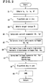
- Fig. 2 is a flowchart illustrating an example of the controlling procedure of the synchronous motor
- Fig. 3A is a view for explaining a principle of a coordinate transformation
- Fig. 3B is a view for explaining the principle of the coordinate transformation
- Fig. 4 is a vector diagram for explaining a phase angle of armature currents
- Fig. 5 is a view illustrating a state transition diagram for explaining a process for obtaining current commands
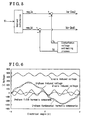
- Fig. 6 is a waveform chart indicating induced voltages, including disturbance voltages, of the synchronous motor
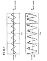
- Fig. 7 is a waveform chart indicating a d-axis and q-axis currents, including the disturbance currents, of the synchronous motor;
- Fig. 8 is a flowchart illustrating an example of a disturbance voltage estimation process on the d-axis and q-axis;
- Fig. 9 is a state transition diagram for explaining a process for calculating voltage commands
- Fig. 10 is a waveform chart illustrating the d-axis and q-axis currents of the synchronous motor obtained after the disturbance voltages on the d-axis and q-axis are suppressed;
- Fig. 11A is a d-axis disturbance voltage table
- Fig. 11B is a q-axis disturbance voltage table
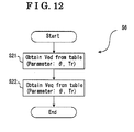
- Fig. 12 is a flowchart illustrating another example of the disturbance voltage estimation process on the d-axis and q-axis;
- Fig. 13 is a block diagram schematically illustrating another configuration example of the synchronous motor control device according to a second embodiment
- Fig. 14 is a flowchart illustrating another example of the controlling procedure of the synchronous motor
- Fig. 15 is a flowchart illustrating an example of a disturbance voltage estimation process on three-phases
- Fig. 16 is a state transition diagram for explaining a process of calculating three-phase voltage commands
- Fig. 17 is a flowchart illustrating another example of the disturbance voltage estimation process on the three-phases
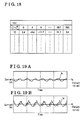
- Fig. 18 illustrates one of three-phase disturbance voltage tables
- Fig. 19 is a waveform chart illustrating the d-axis and q-axis currents of the synchronous motor after the disturbance voltages on the three-phases are suppressed.
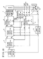
- FIG. 1 is a block diagram schematically illustrating a configuration example of the synchronous motor control device.
- a motor 1 is a three-phase synchronous motor.
- the motor 1 includes a rotor having permanent magnets and a stator that generates a magnetic field for applying a rotational force to the rotor.
- the stator includes stator coils (armature coils) 1u, 1v and 1w that form U-phase, V-phase and W-phase, respectively.
- One end of each of the stator coils 1u, 1v and 1w is commonly connected at an electrical neutral point so as to form a Y-connection (a star-connection).
- each of the stator coils 1u, 1v and 1w is connected to an inverter 8 that will be described below.
- the synchronous motor control device of the first embodiment energises the stator coils 1u, 1v and 1w that form the three-phases via the inverter 8 in response to a target torque applied to the stator coils 1u, 1v and 1w from a torque command calculation portion 3, and then, a rotating magnetic field is generated, thereby driving the synchronous motor 1.
- the synchronous motor control device includes functional portions such as a coordinate transformation portion 2, a current command calculation portion 4, a voltage command calculation portion 5, an inverse coordinate transformation portion 6, a pulse width modulating portion 7 (hereinafter referred to as a PWM portion 7), a disturbance voltage estimating portion 9, a speed detecting portion 11 and the like.
- the functional portions including the torque calculation portion 3 are configured with, for example, a microcomputer and the like. Therefore, the functional portions do not need to be configured to be physically independent as long as each of the functional portions is configured to be achievable by means of a program and the like.
- the functional portions may be configured by combining electronic circuits such as a logic circuit, application specific standard product (ASSP) and the like. Details of each of the functional portions will be described below.
- ASSP application specific standard product
- the inverter 8 that drives the motor 1 converts direct current voltage (DC voltage) into alternating current voltage (AD voltage) based on inverter driving signals pu, pv, pw, nu, nv and nw.
- the inverter 8 is configured with a bridge circuit whose details will be described below. Two witching elements are arranged in series between an electric power source VDC and a ground, i. e. between a positive side and a negative side of a direct current port source. In other words, a series circuit having a high-side switch at the positive side and a low-side switch at the negative side is formed.
- the bridge circuit is formed by three pairs of series circuits described above, being connected in parallel so as to correspond to the U-phase, the V-phase and the W-phase, respectively,
- the other end of each of the stator coils 1u, 1v and 1w is connected to a connecting point of the high-side switch and the low-side switch of each of the series circuits.
- the inverter driving signals pu, pv and pw are signals for driving high-side switches of the U-phase, V-phase and W-phase, respectively.
- the inverter driving signals nu, nv and nw are signals for driving low-side switches of the U-phase, V-phase and W-phase, respectively.
- a power metal-oxide-semiconductor-field-effect-transistor (a power MOSFET, which is hereinafter referred to simply as FET for convenience) is used for the switching elements.
- a boost circuit such as a charge pump is additionally provided.
- the inverter driving signals pu, pv and pw, that drive the high-side switches respectively, are boosted by the boost circuit.
- a flywheel diode which is also referred to as a free-wheel diode and is configured to be connected in parallel with the FET, is provided at each of the FET. Additionally, the flywheel diode may be included into the switching elements such as the FET. Further, other semiconductor elements such as a power transistor, an intelligent power device (IPD), an intelligent power module (IPM) and the like my be used as the switching elements.
- a current sensor 12 (12u, 12v, 12w) that serves as a current detecting portion is provided on lines connecting the inverter 8 and the stator coils 1u, 1v and 1w.
- the current sensor 12 detects the motor current applied to each of the three-phase stator coils 1u, 1v and 1w, In this embodiment, currents iu, iv and iv applied to the three-phase stator coils 1u, 1v and 1w respectively balance each other.
- the current of two phases may be detected and then the current of the rest may be estimated by a calculation at the coordinate transformation portion 2 and the like.
- the coordinate transformation portion 2 serves also as a part of the current detecting portion.
- the motor 1 is provided with a rotational angle sensor (rotation detecting portion) such as a resolver 10 for detecting a rotational angle (mechanical angle) of the rotor of the motor 1.
- the resolver 10 is set depending on the number of poles (number of pairing poles) of the rotor of the motor 1.
- the resolver 10 converts the rotational angle of the rotor into an electrical angle ⁇ and outputs a signal corresponding to the electrical angle ⁇ .
- the speed detecting portion 11 detects number of rotations of the motor 1 (angular velocity ⁇ ) based on the output of the resolver 10.
- the synchronous motor control device of the first embodiment is provided with a vector-control portion that executes a vector-control,
- the vector-control portion is configured at least with the coordinate transformation portion 2, the current command calculation portion 4, the voltage command calculation portion 5 and the inverse coordinate transformation portion 6.
- the vector-control portion obtains the motor currents iu, iv and iw of the motor 1 and the rotational angle (the electrical angle ⁇ ) of the rotor (S1 in Fig. 2 ), obtained in the above-mentioned manner.
- the coordinate transformation portion 2 is a functional portion for coordinate-transforming the motor currents iu, iv and iw on the basis of the electrical angle ⁇ .
- the coordinate transformation portion 2 coordinate-transforms the motor currents iu, iv and iw into a vector component Id of a direct axis (hereinafter referred to as a d-axis), which corresponds to a direction where a magnetic field generated by the permanent magnets that is provided at the rotor of the motor 1, and a vector component Iq of a quadrature axis (hereinafter referred to as a q-axis) that is orthogonal to the d-axis (S2 in Fig. 2 : coordinate transformation process).
- the vector component Id of the d-axis is referred to as the d-axis vector component Id
- the vector component Iq of the q-axis is referred to as the q-axis vector component Iq.
- Fig. 3 is a view for explaining a principle of the coordinate transformation.
- a rotor 1r having bipolar (a pair of poles) permanent magnets m is employed, and a rotational angle of the rotor 1r corresponds to the electrical angle ⁇
- Fig. 3A is a waveform chart illustrating a relationship between current waveforms and the electrical angle ⁇ .
- the current waveforms correspond to positions of the magnetic poles.
- Fig. 3B is a view for explaining a positional relationship between the rotor 1r and a stator 1s at time t1 in Fig. 3A , and further, Fig. 3B illustrates current vectors before and after an execution of the coordinate transformation.
- the rotational angle (the electrical angle ⁇ ) is illustrated as a position of magnetic pole of the rotor 1r with reference to a salient position of the U-phase of the stator 1s.
- a direction of a magnetic field generated by the permanent magnets m arranged at the rotor 1r is represented as the d-axis, and a direction that is orthogonal to the d-axis is represented as the q-axis.
- a torque is generated by applying the sine wave three-phase alternating currents iu, iv and iw to the stator coils 1u, 1v and 1w, respectively, in response to the position of the poles of the rotor 1r.
- a current vector ia indicating a sum of armature currents becomes a sum of vectors of the three-phase currents iu, iv and iw, as illustrated in Fig.
- Fig. 3B illustrates the current vector ia as a vectorial sum of the current iu of the U-phase and the current iv of the V-phase because the current of the W-phase is zero.
- the motor currents iu, iv and iw are coordinate-transformed into the d-axis current Id and the q-axis current Iq.
- the d-axis current Id and the q-axis current Iq are set to be constant without being influenced by the electrical angle ⁇ .
- the d-axis current Id and the q-axis current Iq correspond to a field current and an armature current, respectively, of a direct current motor. Therefore, by executing a vector transformation, a method of controlling the direct current motor having accumulated technology may be adapted to a synchronous motor. This represents one of advantages of vector-controlling the synchronous motor.
- inductances corresponding to the stator coils 1u, 1v and 1w change in response to a positional relationship between each of the corresponding stator coils 1u, 1v and 1w and the rotor 1r, i.e, a positional relationship between each of the corresponding stator coils 1u, 1v and 1w and the position of the magnetic poles.
- stator 1r When the rotor 1r is rotated so that any one of the stator coils 1u, 1v and 1w is positioned so as to correspond to the direction of the d-axis that corresponds to the direction of the magnetic poles, a magnetic path of the any one of the stator coils 1u, 1v and 1w is blocked because the stator coils 1u, 1v and 1w have magnetic resistance proportional to an inverse of magnetic permeability of the permanent magnets.
- the magnetic path of the any one of the stator coils 1u, 1v and 1w is less likely to be blocked because the currents iu, iv and iw pass through a soft magnetic material such as a silicon steel having a large magnetic permeability and a value of the magnetic resistance of the stator coils 1u, 1v and 1w dramatically reduced compared to a case where the currents iu, iv and iw pass through the permanent magnets.
- a q-axis inductance Ld has a larger value than a d-axis inductance Ld.
- a reluctance torque is generated due to a difference between the d-axis inductance Ld and the q-axis inductance Lq.
- a surface permanent magnet synchronous motor hereinafter referred to as a SPMSM or a surface PMSM
- the motor working efficiency is enhanced when the IPMSM is controlled with the d-axis vector component Id as a value other than zero (Id ⁇ 0).
- Id ⁇ 0 the d-axis vector component
- an operational point at which a maximum motor working efficiency is achieved changes in response to a current phase angle ⁇ formed by the d-axis current Id and the q-axis current Iq.
- the current phase angle ⁇ is an angle represented by the following equation (equation 3) and in Fig. 4 .
- a total torque of the motor 1 is represented by the following equation (equation 4) where Pn indicates number of pairing poles, ⁇ a indicates an interlinkage magnetic flux of the armatures, ia indicates the armature currents, Ld indicates the d-axis inductance, Lq indicates the q-axis inductance and ⁇ indicates the current phase angle.
- equation 4 the magnet torque is represented by the first term within the braces, and the reluctance torque is represented by the second term. Additionally, in view of equation 3 and Fig. 4 , the following equations (equations 5 to 7) are apparently satisfied. Hence, torque equation 4 is also represented by equation 8.
- I ⁇ a 2 I ⁇ d 2 + I ⁇ q 2
- the armature current Ia includes the d-axis current Id and the q-axis current Iq.
- each of the torque equations represented in equations 4 and 8 is defined as an equation that represents the torque of the motor 1 by using the interlinkage magnetic flux ⁇ a, the d-axis inductance Ld, q-axis inductance Lq, d-axis current Id and the q-axis current Iq.
- a torque T of the motor 1 is set to any desired value by controlling the d-axis current Id and the q-axis current Iq.
- the torque command calculation portion 3 is the functional portion that calculates the total torque T necessary for the motor 1 and outputs a torque command Tr (target torque) to the current command calculation portion 4.
- Tr target torque
- the motor 1 is adapted to electric appliances, for example, a washing machine
- a necessary torque is calculated on the basis of an operation phase for washing, dehydration and the like, and an amount of the laundry and the like
- a necessary torque is calculated on the basis of command input via an accelerator, a brake and the like, and detection results of a vehicle speed sensor and the like, Further, a feedback control using the angular velocity ⁇ of the motor 1, detected by the speed detecting portion 11, is also executed.
- the current command calculation portion 4 obtains the torque command Tr (target torque) calculated by the torque command calculation portion 3 (S3 in Fig. 2 ). Then, the current command calculation portion 4 calculates a d-axis current command Idr and a q-axis current command Iqr on the basis of the obtained torque command Tr (S4 in Fig. 2 : current command calculation process). For example, the torque equation represented by equation 2 may be transformed into an equation representing the armature current Ia.
- the current command calculation portion 4 may calculate the d-axis current command Idr and the q-axis current command Iqr by solving the transformed torque equation by substituting the torque command Tr or other parameters therein, and then by decomposing the armature current Ia into the d-axis vector and the q-axis vector on the basis of the phase angle ⁇ .
- the d-axis current command Idr and the q-axis current command Iqr may be calculated from equation 8.
- a d-axis current deviation led and a q-axis current deviation Ieq may be defined as the d-axis current command Idr and the q-axis current command Iqr, respectively (See equations 9 and 10).
- the d-axis current deviation Ied is a difference between a requested d-axis current req_Id, calculated on the basis of the torque command Tr, and the actual d-axis motor current Id.
- the q-axis current deviation Ieq is a difference between a requested q-axis current req_Iq, calculated on the basis of the torque command Tr, and the actual q-axis motor current Iq.
- the d-axis current deviation led and the q-axis current deviation Ieq may be calculated at the voltage command calculation portion 5, which will be described below.
- Ied req_Id - Id
- Ieq req_Iq - Iq
- the voltage command calculation portion 5 calculates a d-axis voltage command Vdr and a q-axis voltage command Vqr from the d-axis current command Idr and the q-axis current command Iqr, respectively, each of which is calculated by the current command calculation portion 4, on the basis of a voltage equation (S5 in Fig. 2 ).
- a voltage equation representing a d-axis voltage Vd and a q-axis voltage Vq is represented by the following equation (equation 11) where ⁇ a indicates the interlinkage magnetic flux of the armatures, ⁇ indicates the angular velocity, Id indicates the d-axis current, Iq indicates the q-axis current, Ld indicates the d-axis inductance, Lq indicates the q-axis inductance, Ra indicates an armature resistance and p indicates a differential operator.
- Vd Vq Ra + pLd - ⁇ Lq ⁇ Ld Ra + pLq ⁇ Id Iq + 0 ⁇ a
- equation 11 is a voltage equation representing the voltage for driving the motor 1 by using the impedance of the stator coils 1u, 1v and 1w of the motor 1 including the interlinkage magnetic flux ⁇ a, the d-axis inductance Ld and the q-axis inductance Lq, the d-axis current Id and the q-axis current Iq.
- the voltage command calculation portion 5 calculates the d-axis voltage Vd and the q-axis voltage Vq by substituting the d-axis current command Idr and the q-axis current command Iqr or the other parameters into voltage equation 11 (S5 in Fig. 2 : d-axis and q-axis voltage calculation process (voltage command calculation process)).
- the calculated d-axis voltage Vd and q-axis voltage Vq are output as the d-axis voltage command Vdr and the q-axis voltage command Vqr, respectively, unless modification on the d-axis voltage command Vdr and the q-axis voltage command Vqr is required.
- the process executed at S5 in Fig. 2 functions as a voltage calculation process.
- the process executed at S5 in Fig, 2 may function as a voltage command calculating process together with a process executed at S7, which will be described below.
- the d-axis voltage command Idr and the q-axis voltage command Iqr are inversely transformed into three-phase voltage commands vur, vvr and vwr at the inverse coordinate transformation portion 6.
- the three-phase voltage commands vur, vvr and vwr are inputted to the inverter 8 via the FWM portion 7, then transformed into the three-phase alternating currents (AD) by which the stator coils 1u, 1v and 1w of the motor 1 are energised.
- AD three-phase alternating currents
- FIG. 6 is a waveform chart indicating the simulation result of an induced voltage of the U-plaxse stator coil 1u (hereinafter referred to as a U-phase induced voltage) relative to induced voltages on the d-axis and q-axis (hereinafter referred to as a d-axis induced voltage and a q-axis induced voltage).
- the induced voltage is an electromotive voltage generated at a coil in proportion to a number of rotations of the motor while being driven.
- Fig. 7 is a waveform chart indicating the simulation results of the d-axis current Id and the q-axis current Iq relative to Fig. 6 , and further, Fig.
- FIG. 7 illustrates d-axis current and the q-axis current generated by the d-axis induced voltage and the q-axis induced voltage, respectively.
- the pulsations of the d-axis current Id and the q-axis current Iq cause torque fluctuation.
- the pulsations, i.e. disturbance currents, included in the d-axis current Id and the q-axis current Iq are caused by the pulsations, i.e. disturbance voltages, included in the d-axis induced voltage and the q-axis induced voltages, respectively, as illustrated in Fig. 6 .
- a fifth harmonic included in the U-phase induced voltage as a high-order harmonic component is illustrated with an alternate long and short dash line
- the U-phase induced voltage expressed by a wave in a sin-wave shape, which indicates fundamental harmonic components, as illustrated with a dashed line in Fig. 6 .
- the U-phase induced voltage is expressed by a distorted wave, as illustrated with a solid line in Fig. 6 .
- the three-phase induced voltages such as the U-phase induced voltage expressed by the distorted wave may be approximated to voltages expressed by sin-waves. If the three-phase induced voltages are approximated to the voltages expressed by the sin-waves, respectively, disturbance currents superimposed on the motor currents are suppressed, thereby suppressing the torque fluctuation.
- the disturbance voltage estimating portion 9 is a functional portion that estimates the disturbance voltages causing turbulence on motor currents and included in the induced voltages induced by three-phase driving voltages, generated by the inverter 8 on the basis of the voltage commands vur, vvr, vwr. Further, the disturbance voltage estimating portion 9 is the functional portion that feed-forwards the estimated results to the vector-control portion. In this embodiment, the disturbance voltage estimating portion 9 estimates a d-axis disturbance voltage Ved and a q-axis disturbance voltage Veq by identifying the high-order harmonic components on the d-axis voltage command Vdr and the q-axis voltage command Vqr (S6 in Fig. 2 : disturbance voltage estimation process). As illustrated in Fig.
- the high-order harmonics included in the induced voltages on the d-axis and the q-axis are harmonics of higher-order than fifth harmonics included in the three-phase induced voltages. More specifically, the high-order harmonic included in each of the induced voltages on the d-axis and the q-axis is a sixth harmonic.
- the disturbance voltages having the sixth harmonic component are identified as a function of the electrical angle ⁇ of the motor 1, as indicated in the following equations (equations 12 and 13). 'A' in equation 12 and 'B' in equation 13 are constants.
- the disturbance voltage estimating portion 9 calculates and estimates the d-axis disturbance voltage Ved and the q-axis disturbance voltage Veq in response to the electrical angle ⁇ , changing in response to rotation of the motor 1, and on the basis of equations 12 and 13 in which the high-order harmonic component is identified as the function of the electrical angle ⁇ of the motor 1 (see Fig. 8 ).
- the estimated d-axis and q-axis disturbance voltages Ved and Veq are feed-forwarded to the vector-control portion.
- the estimated d-axis and q-axis disturbance voltages Ved and Veq are feed-forwarded to the voltage command calculation portion 5.
- the voltage command calculation portion 5 calculates the modified 6-axis voltage command Vdr and the q-axis voltage command Vqr, as indicated in the following equations (equations 14 and 15) (S7 in Fig. 2 : Voltage command calculation process, modification process). More specifically, the voltage command calculation portion 5 obtains the modified d-axis voltage command Vdr and the q-axis voltage command Vqr by subtracting the d-axis disturbance voltage Ved and the q-axis disturbance voltage Veq, estimated by the disturbance voltage estimating portion 9, from the d-axis voltage Vd and the q-axis voltage Vq, both of which are the voltage commands before being modified, respectively. In other words, the voltage command calculation portion 5 offsets the high-order harmonic components, included in the voltage commands before being modified, with the disturbance voltages in order to modify the d-axis voltage Vd and the q-axis voltage Vq.
- Vdr Vd - Ved
- Vqr Vq - Veq
- differences between the d-axis voltage Vd and the q-axis voltage, both of which are the calculation results of the voltage command calculation, and the d-axis disturbance voltage Ved and the q-axis disturbance voltage Veq, both of which are the results of the disturbance voltage estimation process, respectively, are calculated in order to obtain the d-axis voltage command Vdr and the q-axis voltage command Vqr.
- the calculated d-axis voltage command Vdr and the q-axis voltage command Vqr are inversely coordinate-transformed into the voltage commands vur, wr and vwr.
- the differences between the d-axis voltage Vd and the q-axis voltage Vq and the d-axis disturbance voltage Ved and the q-axis disturbance voltage Veq, respectively, are calculated at the voltage command calculation portion 5.
- the differences between the d-axis voltage Vd and the q-axis voltage Vq and the d-axis disturbance voltage Ved and the q-axis disturbance voltage Veq, respectively, are calculated before executing the inverse coordinate transformation, the differences may be calculated at any timing.
- the voltage command calculation portion 5 may output the d-axis voltage Vd and the q-axis voltage Vq, both of which are the calculation results of the voltage command calculation, as the d-axis voltage command Vdr and the q-axis voltage command Vqr, respectively, and then, the differences between the output d-axis voltage command Vdr and the q-axis voltage command Vqr and the d-axis disturbance voltage Ved and the q-axis disturbance voltage Veq, respectively, may be calculated at the inverse coordinate transformation portion 6, which will be described below.
- the inverse coordinate transformation portion 6 transforms the d-axis voltage command Vdr and the q-axis voltage command Vqr into the U-phase, V-phase and W-phase voltage commands vur, vvr and vwr, in a manner inverse to the coordinate transformation executed by the coordinate transformation portion 2 (S8 in Fig. 2 : inverse coordinate transformation process, three-phase voltage commands calculation process).
- the coordinate transformation portion 2 S8 in Fig. 2 : inverse coordinate transformation process, three-phase voltage commands calculation process.
- the d-axis voltage command Vdr and the q-axis voltage command Vqr are inversely coordinate transformed, and then output as the U-phase, V-phase and W-phase voltage commands vur, vvr and vwr.
- the d-axis voltage command Vdr and the q-axis voltage command Vqr may be inversely coordinate-transformed into the voltage commands of two phases, and then the voltage command of the rest may be calculated on the basis of the voltage commands of the two phases.
- the d-axis voltage command Vdr and the q-axis voltage command Vqr are inversely coordinate transformed into the U-phase voltage command vur and the V-phase voltage command vvr.
- the W-phase voltage command vwr is calculated on the basis of the obtained U-phase voltage command vur and the V-phase voltage command vvr.
- the inverse coordinate transformation is executed in a manner inverse to the coordinate transformation, which is described above in accordance with Figs. 2 and 3 . Hence, the detailed description on method of the inverse coordinate transformation will be omitted.
- the PWM portion 7 generates the driving signals pu, pv, pw, nu, nv and nw for driving the six switching elements of the inverter 8 by executing the pulse width modulation (PWM) on the basis of the three-phase voltage commands vur, vvr and vwr (S9 in Fig. 2 : modulation process).
- the driving signals pu, pv and pw are the driving signals for the switching elements that function as the high-side switches, respectively.
- the driving signals nu, nv and nw are the driving signals for the switching elements that function as the low-side switches, respectively.
- a dead time is set at each of the driving signals in order to prevent a line between the positive side and the negative side of the electric power sources to be short-circuited when the high-side switches and the low-side switches, which are connected in series, are simultaneously turned on. Therefore, it may be preferable that a dead time compensation portion (not shown) is additionally provided to the synchronous motor control device illustrated in Fig. 1 .
- the PWM portion 7 may be configured to include a dead time compensation function.
- the inverter 8 converts direct current (DC) voltage into alternating current (AD) voltage on the basis of the inverter driving signals pu, pv, pw, nu, nv and nw. Then, the armatures, i.e. stator coils 1u, 1v and 1w, are energised by the converted AD voltage. As a result, the rotating magnetic field is generated, thereby driving the motor 1.
- DC direct current
- AD alternating current
- Fig. 10 shows the simulation results of the d-axis current Id and the q-axis current Iq in a case where the motor 1 is driven by using the d-axis voltage command Vdr and the q-axis voltage command Vqr that are modified in the above-described manner. Comparing to waveforms of the d-axis current Id and the q-axis current Iq obtained in the case where the d-axis voltage command Vdr and the q-axis voltage command Vqr are not modified, it is apparent that the disturbance currents caused by the high-order harmonic are largely suppressed when the modified d-axis voltage command Vdr and the q-axis voltage command Vqr are utilized.
- Each of the d-axis disturbance voltage Ved and the q-axis disturbance voltage Veq includes the sixth high-order harmonic component.
- a basic equation of the armatures (stator coils) having a three-phase voltage model is represented in the following equation (equation 19) where R indicates the armature resistance (DC resistance), I indicates a three-by-three identity matrix, ⁇ indicates a vector of number of the interlinkage magnetic fluxes, ⁇ f indicates a vector of number of the interlinkage magnetic flux of the permanent magnets, i indicates a three-phase current vector, v indicates a three-phase voltage vector, and L indicates a sum of self-inductances and mutual inductances, Additionally, ' ⁇ ' in equation 19 indicates a vector.
- Equation 20 when self-inductances of the stator-coils 1u, 1v and 1w, forming the three-phases, are defined as Lu, Lv and Lw, respectively, and mutual inductances of the stator coils 1u, 1v and 1 w are defined as Muv, Muw, Mvu, Mvw, Mwu and Mwv.
- L Lu Muv Muw Mvu Lv Mvw Mwu Mwv Lw
- the self inductances Lu, Lv and Lw are represented in the following equation (equation 21) where la indicates a linkage inductance, La indicates DC generated by the self-inductance, and Las indicates an amplitude generated by the self inductance.
- the mutual inductances Muv, Muw, Mvu, Mvw, Mwu and Mwv are represented in the following equation (equation 22) where la indicates the linkage inductance, La indicates the DC generated by the self-inductance, and Lad indicates the amplitude generated by the self-inductance.
- Number of the interlinkage magnetic flux of three-phases ⁇ fu, ⁇ fv and ⁇ fw generated by the permanent magnets may be represented in the following equation (equation 23) when the high-order harmonic component is taken into consideration.
- Subscript 'n' of, for example, ' ⁇ f n ' and ' ⁇ n ' in equation 23 indicates a degree of the high-order harmonic. More specifically, ' ⁇ f n ' indicates amplitude of a n-order harmonic, and ' ⁇ n ' indicates a phase of the n-order harmonic. Additionally, as influence of harmonics of higher-order than seventh harmonics may not necessarily be taken into consideration, the high-order harmonic components up to the seventh harmonic are taken into consideration in this embodiment.
- the voltage is obtained by differentiating the interlinkage magnetic flux.
- equation 23 induced voltages of the U-phase, V-phase and W-phase Eu, Ev and Ew (hereinafter referred to as a U-phase induced voltage Eu, a V-phase induced voltage Ev and a W-phase induced voltage Ew) are obtained, as indicated in the following equation (equation 24).
- Equations 12 and 13 represent the d-axis disturbance voltage Ved on the d-axis induced voltage and the q-axis disturbance voltage Veq on the q-axis induced voltage, respectively, in the case where the constants are identified relative to the motor 1.
- the synchronous motor control device is structured substantially the same as the synchronous motor device of the first embodiment. Hence, the detailed description of the structure of the synchronous motor control device according to the second embodiment will be omitted. Additionally, the control procedure of the synchronous motor of the second embodiment is substantially the same as the control procedure of the synchronous motor of the first embodiment. Hence, the detailed description of the control procedure of the synchronous motor of the second embodiment will be omitted.
- the disturbance voltage estimating portion 9 calculates and estimates the d-axis disturbance voltage Ved and the q-axis disturbance voltage Veq on the basis of equations 12 and 13, respectively, at S6 in Fig. 2 .
- the disturbance voltage estimating portion 9 does not execute a calculation on the basis of an equation, but the disturbance voltage estimating portion 9 obtains and estimates the d-axis disturbance voltage Ved and the q-axis disturbance voltage Veq by referring to a table of the d-axis disturbance voltage Ved illustrated in Fig. 11 and a table of the q-axis disturbance voltage Veq illustrated in Fig. 11B , respectively.
- Fig. 11A is a table illustrating the d-axis disturbance voltage Ved.
- Fig. 11B is a table illustrating the q-axis disturbance voltage Veq. Both tables are stored in a storage media, e.g. a flash memory.
- the storage media such as the flash memory is configured by being included in, for example, a microcomputer within which the vector-control portion is configured, electronic circuitry to which the microcomputer is provided, and the like.
- Each table illustrated in Fig. 11 is configured as, for example, a relative table in which the torque command Tr and the electrical angle ⁇ are defined as parameters.
- the electrical angle ⁇ is not measured in radian (rad), but measured in degree (deg).
- the parameters are not limited to the torque T and the electrical angle ⁇ , but a current root mean square value and the electrical angle ⁇ may be set as the parameters.
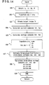
- the disturbance voltage estimating portion 9 obtains the d-axis disturbance voltage Ved and the q-axis disturbance voltage Veq with reference to the tables, as illustrated in Fig. 12 , as the process executed at S6 in Fig. 2 .
- the disturbance voltage estimating portion 9 obtains the d-axis disturbance voltage Ved from the table illustrated in Fig. 11A (S21), and the disturbance voltage estimating portion 9 obtains the q-axis disturbance voltage Veq from the table illustrated in Fig. 11B (S22), with the torque command Tr and the electrical angle ⁇ being used as the parameters.
- Increase of calculation load applied to the disturbance voltage estimating portion 9 is restricted if the synchronous motor control device is configured to obtain the d-axis disturbance voltage Ved and the q-axis disturbance voltage Veq by referring to the tables, depending on calculation capacity, calculation load and the like of the microcomputer configuring the vector-control portion.
- Fig. 13 is a block diagram schematically illustrating a configuration example of the synchronous motor control device related to the third embodiment.
- Fig. 14 is a flowchart illustrating an example of controlling procedure executed by the synchronous motor control device.
- the disturbance voltages are estimated on the d-axis and the q-axis.
- the disturbance voltage estimating portion 9 estimates disturbance voltages on the three-phases. As illustrated in Fig.
- the disturbance voltage estimating portion 9 estimates a U-phase disturbance voltage veu, a V-phase disturbance voltage vev and a W-phase disturbance voltage vew, and then the estimated results are feed-forwarded to the vector-control portion.
- the estimated results are feed-forwarded to the inverse coordinate transformation portion 6.
- the other portions except for the disturbance voltage estimating portion 9 are configured substantially the same as the configuration example of the first and second embodiments described in accordance with Fig. 1 . Hence, the detailed description on the same structure with the first and the second embodiments will be omitted.
- the vector-control portion obtains three-phase motor currents iu, iv, iw and the rotational angle (the electrical angle ⁇ ) of the rotor (S31 in Fig. 14 ).
- the coordinate transformation portion 2 coordinate-transforms the three-phase motor currents iu, iv and iw into a vector component Id of the d-axis (hereinafter referred to as a d-axis vector component Id), corresponding to the direction where the magnetic field being generated by the permanent magnets provided at the rotor of the motor 1, and a vector component Iq of the q-axis (hereinafter referred to as a q-axis vector component Iq) orthogonal to the d-axis (S32 in Fig.
- the current command calculation portion 4 obtains the torque command Tr (the target torque) calculated by the torque command calculation portion 3 (S33 in Fig. 14 ). Then, the current command calculation portion 4 calculates the d-axis current command Idr and the q-axis current command Iqr (S34 in Fig. 14 : current command calculation process).
- Tr the target torque
- Idr the current command calculation portion 4 calculates the d-axis current command Idr and the q-axis current command Iqr (S34 in Fig. 14 : current command calculation process).
- the voltage command calculation portion 5 calculates the d-axis voltage Vd and the q-axis voltage Vq by substituting the d-axis current command Idr, the q-axis current command Iqr or the other parameters into the voltage equation represented by equation 11 (S35 in Fig. 14 : d-axis and q-axis voltages calculation process, voltage command calculation process).
- each of the d-axis voltage Vd and the q-axis voltage Vq calculated on the basis of voltage equation 11, is modified by taking each of the d-axis disturbance voltage Ved and the q-axis disturbance voltage Veq into consideration in order to obtain each of the d-axis voltage command Vdr and the q-axis voltage command Vqr.
- the calculated d-axis voltage Vd and the q-axis voltage Vq are output as the d-axis voltage command Vdr and the q-axis voltage command Vqr, respectively, instead of executing the modification on the d-axis voltage Vd and the q-axis voltage Vq.
- the inverse coordinate transformation portion 6 transforms the d-axis voltage command Vdr and the q-axis voltage command Vqr into the three-phase voltages vu, w and vw in the manner inverse to the coordinate transformation executed by the coordinate transformation portion 2 (S36 in Fig. 14 : inverse coordinate transformation process).
- the three-phase voltages balance each other.
- the d-axis voltage command Vdr and the q-axis voltage command Vqr may be inversely coordinate-transformed into the voltages of two phases, and then the voltage of the rest may be calculated on the basis of the voltage commands of the two phases.
- the d-axis voltage command Vdr and the q-axis voltage command Vqr are inversely coordinate-transformed into the U-phase voltage vu and the V-phase voltage w. Then, the W-phase voltage vw is calculated on the basis of the obtained U-phase voltage vu and the V-phase voltage vv.
- the inverse coordinate transformation is executed in the same manner as in S8 in Fig. 2 of the first embodiment, and as indicated in equations 16, 17 and 18.
- the d-axis voltage command Vdr and the q-axis voltage command Vqr are modified, by taking the respective d-axis disturbance voltage Ved and the q-axis disturbance voltage Veq into consideration.
- the inversely coordinate-transformed three-phase voltages vu, vv and vw are output as the three-phase voltage commands vur, vvr and vwr.
- the U-phase voltage vu, the V-phase voltage vv and the W-phase voltage vw are modified, with taking the disturbance voltages veu, vev and vew, respectively, into consideration.
- the U-phase voltage command vur, the V-phase voltage command wr and the W-phase voltage command vwr are obtained.
- the U-phase, V-phase and W-phase disturbance voltages veu, vev and vew are estimated by the disturbance voltage estimating portion 9 (S37 in Fig. 14 : disturbance voltage estimation process).
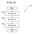
- the disturbance voltage estimating portion 9 calculates the U-phase disturbance voltage veu, the V-phase disturbance voltage vev and the W-phase disturbance voltage vew, as indicated in S41, S42 and S43 in Fig. 15 , by executing calculation of, for example, equation 24.
- the plural high-order harmonics are included in equation 24, which complicates the equation.
- equation 24 may be appropriately reduced. For example, it is demonstrable by an experimental test, computer analysis and the like that influence of the fifth harmonic and the seventh harmonic in equation 24 is much greater than influence of high-order harmonics equal to or lower than the third harmonic.
- the inverse coordinate transformation portion 6 subtracts the U-phase disturbance voltage veu, the V-phase disturbance voltage vev and the W-phase disturbance voltage vew from the U-phase voltage vu, the V-phase voltage w and the W-phase voltage vw, respectively.
- the inverse coordinate transformation portion 6 calculates the U-phase, V-phase and W-phase voltage commands vur, vvr and vwr by offsetting the disturbance voltages veu, vev and vew by subtracting the disturbance voltages veu, vev and vew from the voltages vu, vv and vw, respectively (S38 in Fig. 14 : three-phase voltage command calculation process, modification process).
- the inverse coordinate transformation portion 6 calculates differences between the U-phase, V-phase and W-phase voltages vu, w and vw and the U-phase, V-phase and W-phase disturbance voltages veu, vev and the vew, respectively.
- the differences my be calculated at any timing.
- the inverse coordinate transformation portion 6 alternatively outputs the U-phase voltage vu, the V-phase voltage vv and the W-phase voltage vw, which are obtained as the results of the inverse coordinate transformation, as the U-phase voltage command vur, the V-phase voltage command wr and the W-phase voltage command vwr, respectively, and then the differences between the U-phase, V-phase and W-phase voltage commands vur, wr and vwr and the U-phase, V-phase and W-phase disturbance voltages veu, vev and vew, respectively, may be calculated at the PWM portion 7 before an execution of a modulation process.
- the PWM portion 7 executes the PWM in order to generate the driving signals pu, pv, pw, nu, nv and nw for driving the six switching elements of the inverter 8 on the basis of the U-phase voltage command vur, the V-phase voltage command vvr and he W-phase voltage command vwr.
- the inverter 8 converts the DC voltage into the AD voltage on the basis of the inverter driving signals pu, pv, pw, nu, nv and nw. Then, the armatures, i.e. the stator coils 1u, 1v and 1w, are energised by the converted DC voltage. As a result, the rotating magnetic field is generated, thereby driving the motor 1.
- a fourth embodiment of the synchronous motor control device and the synchronous motor control method will be described below.
- a modified example of the third embodiment will be described in the fourth embodiment.
- the synchronous motor device of the fourth embodiment is configured substantially the same as the synchronous motor control device of the third embodiment illustrated in Fig. 13 . Therefore, the detailed description on the structure of the synchronous motor control device of the fourth embodiment will be omitted.
- the controlling procedure of the synchronous motor control device of the fourth embodiment is substantially the same as the controlling procedure of the synchronous motor control device of the third embodiment. Therefore, the detailed description on the controlling procedure of the synchronous motor control device will be omitted.
- the disturbance voltage estimating portion 9 estimates the three-phase disturbance voltages veu, vev and vew on the basis of the calculation, as illustrated in Fig. 15 , as the process executed at S37 in Fig. 14 .
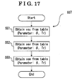
- the disturbance voltage estimating portion 9 does not execute a calculation on the basis of an equation, but obtains the three-phase disturbance voltages veu, vev and vew by referring to correlation tables, for example, a correlation table illustrated in Fig. 18 , as shown in a flowchart illustrated in Fig. 17 .
- Fig. 18 illustrates a part of a table of the U-phase disturbance voltage veu as an example.
- the tables of the three-phase disturbance voltages are stored in the storage media, e.g. a flash memory.
- the storage media such as the flash memory is configured by being included in, for example, the microcomputer within which the vector-control portion is configured, electronic circuitry to which the microcomputer is provided, and the like.
- each table of the disturbance voltages is configured with defining the torque command Tr and the electrical angle ⁇ as the parameters.
- the electrical angle ⁇ is not measured in radian (rad), but measured in degree (deg) in Fig. 18
- the parameters are not limited to the torque T and the electrical angle ⁇ , but the current root mean square value and the electrical angle ⁇ may be set as the parameters.
- the disturbance voltage estimating portion 9 obtains the U-phase disturbance voltage veu, the V-phase disturbance voltage vev and the W-phase disturbance voltage vew with reference to the tables as the process executed at S37 in Fig. 14 , as illustrated in Fig. 17 .
- the disturbance voltage estimating portion 9 obtains the U-phase disturbance voltage veu from the table illustrated in Fig. 18 with the torque command Tr and the electrical angle ⁇ defined as the parameters (S51).
- the disturbance voltage estimating portion 9 obtains the V-phase disturbance voltage vev from the corresponding table (now shown) (S52) and the W-phase disturbance voltage vew from the corresponding table (now shown) (S53).
- the increase of the calculation load applied to the disturbance voltage estimating portion 9 is restricted if the synchronous motor control device is configured to obtain the U-phase disturbance voltage veu, the V-phase disturbance voltage vev and the W-phase disturbance voltage vew by referring to the tables, depending on the calculation capacity, the calculation load and the like of the microcomputer configuring the vector-control portion.
- the synchronous motor control device is configured to obtain the U-phase disturbance voltage veu, the V-phase disturbance voltage vev and the W-phase disturbance voltage vew by referring to the tables, depending on the calculation capacity, the calculation load and the like of the microcomputer configuring the vector-control portion.
- the U-phase disturbance voltage veu, the V-phase disturbance voltage vev and the W-phase disturbance voltage vew are calculated on the basis of formulas, a relatively complicated calculation needs to be executed.
- Fig. 19 illustrates the simulation results of the armature currents in the case where the motor 1 is driven by using the U-phase voltage command vur, the V-phase voltage command vvr and the W-phase voltage command vwr that are modified in the above-described manner.
- the modified U-phase, V-phase and W-phase voltage commands vur, vvr and vwr are represented by the d-axis and q-axis currents. Comparing to the d-axis and q-axis currents, illustrated in Fig.
- a synchronous motor control device includes a vector-control portion including a coordinate transformation portion (2) for coordinate-transforming motor currents (iu, iv, iw) into a d-axis vector component (Id) and a q-axis vector component (Iq), a current command calculation portion (4) for calculating a d-axis current command (Idr) and a q-axis current command (Iqr) based on the vector-transformed respective d-axis and q-axis motor currents (Id, Iq), and a target torque (Tr), a voltage command calculation portion (5) for calculating a d-axis voltage command (Vdr) and a q-axis voltage command (Vqr) based on the d-axis and q-axis current commands
Landscapes
- Engineering & Computer Science (AREA)
- Power Engineering (AREA)
- Control Of Ac Motors In General (AREA)
- Control Of Motors That Do Not Use Commutators (AREA)
Applications Claiming Priority (1)
| Application Number | Priority Date | Filing Date | Title |
|---|---|---|---|
| JP2007176399A JP2009017676A (ja) | 2007-07-04 | 2007-07-04 | 同期モータの制御装置及び制御方法 |
Publications (2)
| Publication Number | Publication Date |
|---|---|
| EP2012425A1 true EP2012425A1 (fr) | 2009-01-07 |
| EP2012425B1 EP2012425B1 (fr) | 2009-12-30 |
Family
ID=39764087
Family Applications (1)
| Application Number | Title | Priority Date | Filing Date |
|---|---|---|---|
| EP08159088A Expired - Fee Related EP2012425B1 (fr) | 2007-07-04 | 2008-06-26 | Dispositif de commande de moteur synchrone et procédé de commande de moteur synchrone |
Country Status (3)
| Country | Link |
|---|---|
| EP (1) | EP2012425B1 (fr) |
| JP (1) | JP2009017676A (fr) |
| DE (1) | DE602008000476D1 (fr) |
Cited By (12)
| Publication number | Priority date | Publication date | Assignee | Title |
|---|---|---|---|---|
| CN102215025A (zh) * | 2010-04-08 | 2011-10-12 | 欧姆龙汽车电子株式会社 | 电动机驱动装置 |
| ITVA20100046A1 (it) * | 2010-06-04 | 2011-12-05 | St Microelectronics Srl | Metodo di controllo di un motore sincrono trifase a magneti permanenti per ridurre il rumore acustico e relativo dispositivo di controllo |
| WO2012146248A3 (fr) * | 2011-04-29 | 2013-05-02 | Danfoss Drives A/S | Réduction de bruit d'harmonique |
| EP2504916B1 (fr) * | 2009-11-23 | 2015-05-20 | Robert Bosch GmbH | Procédé de compensation de couples perturbateurs dans des machines-outils électriques |
| RU2566301C2 (ru) * | 2009-06-05 | 2015-10-20 | Реел С.Р.Л. | Способ управления двигателем |
| WO2016180469A1 (fr) * | 2015-05-11 | 2016-11-17 | Thyssenkrupp Presta Ag | Système de direction assistée électrique à compensation d'ondulation |
| EP2287032A3 (fr) * | 2009-07-30 | 2017-07-12 | Hitachi Automotive Systems, Ltd. | Dispositif de conversion d'alimentation dans une voiture |
| CN109287137A (zh) * | 2016-06-21 | 2019-01-29 | 株式会社日立功率半导体 | 马达驱动装置以及使用其的空调室外机 |
| CN109693658A (zh) * | 2017-10-20 | 2019-04-30 | 现代自动车株式会社 | 混合动力车辆的控制方法 |
| US10812002B2 (en) | 2016-10-13 | 2020-10-20 | Zf Automotive Germany Gmbh | Control system for electric motor circuit |
| CN112234880A (zh) * | 2020-11-04 | 2021-01-15 | 湖南大学 | 永磁同步电机mtpa控制方法、装置、设备及存储介质 |
| EP4287497A1 (fr) * | 2022-05-31 | 2023-12-06 | Robert Bosch GmbH | Procédé de fonctionnement silencieux d'un dispositif de moteur électrique, dispositif de moteur électrique et moteur thermique |
Families Citing this family (6)
| Publication number | Priority date | Publication date | Assignee | Title |
|---|---|---|---|---|
| WO2013073026A1 (fr) * | 2011-11-16 | 2013-05-23 | 株式会社日立製作所 | Dispositif de conversion d'énergie |
| JP6438226B2 (ja) * | 2014-07-24 | 2018-12-12 | 日産自動車株式会社 | モータ制御装置及びモータ制御方法 |
| JP2016111788A (ja) * | 2014-12-04 | 2016-06-20 | 株式会社ジェイテクト | 回転電機の制御装置 |
| JP6753326B2 (ja) * | 2017-02-03 | 2020-09-09 | 株式会社豊田自動織機 | モータ制御装置 |
| JP7374813B2 (ja) * | 2020-02-28 | 2023-11-07 | サンデン株式会社 | モータ制御装置 |
| JP2023005629A (ja) * | 2021-06-29 | 2023-01-18 | 株式会社日立産機システム | 電力変換装置 |
Citations (5)
| Publication number | Priority date | Publication date | Assignee | Title |
|---|---|---|---|---|
| JPH03256587A (ja) * | 1990-01-17 | 1991-11-15 | Fuji Electric Co Ltd | 電力変換器の電流制御回路 |
| JPH09215398A (ja) * | 1996-01-29 | 1997-08-15 | Nissan Motor Co Ltd | インバータの制御装置 |
| JP2004282873A (ja) * | 2003-03-14 | 2004-10-07 | Meidensha Corp | 同期電動機のセンサレス計測方法、および同期電動機のセンサレス可変速装置 |
| JP2006320039A (ja) | 2005-05-10 | 2006-11-24 | Toyota Motor Corp | モータ駆動システムの制御装置 |
| US20070085508A1 (en) * | 2005-10-13 | 2007-04-19 | Denso Corporation | Method of estimating magnetic pole position in motor and apparatus of controlling the motor based on the estimated position |
Family Cites Families (2)
| Publication number | Priority date | Publication date | Assignee | Title |
|---|---|---|---|---|
| JP3686987B2 (ja) * | 1995-09-19 | 2005-08-24 | 株式会社安川電機 | Ipmモータの制御方法及び制御装置 |
| JP4154149B2 (ja) * | 2001-12-28 | 2008-09-24 | 株式会社東芝 | ベクトル制御インバータ装置 |
-
2007
- 2007-07-04 JP JP2007176399A patent/JP2009017676A/ja active Pending
-
2008
- 2008-06-26 DE DE602008000476T patent/DE602008000476D1/de active Active
- 2008-06-26 EP EP08159088A patent/EP2012425B1/fr not_active Expired - Fee Related
Patent Citations (5)
| Publication number | Priority date | Publication date | Assignee | Title |
|---|---|---|---|---|
| JPH03256587A (ja) * | 1990-01-17 | 1991-11-15 | Fuji Electric Co Ltd | 電力変換器の電流制御回路 |
| JPH09215398A (ja) * | 1996-01-29 | 1997-08-15 | Nissan Motor Co Ltd | インバータの制御装置 |
| JP2004282873A (ja) * | 2003-03-14 | 2004-10-07 | Meidensha Corp | 同期電動機のセンサレス計測方法、および同期電動機のセンサレス可変速装置 |
| JP2006320039A (ja) | 2005-05-10 | 2006-11-24 | Toyota Motor Corp | モータ駆動システムの制御装置 |
| US20070085508A1 (en) * | 2005-10-13 | 2007-04-19 | Denso Corporation | Method of estimating magnetic pole position in motor and apparatus of controlling the motor based on the estimated position |
Cited By (22)
| Publication number | Priority date | Publication date | Assignee | Title |
|---|---|---|---|---|
| RU2566301C2 (ru) * | 2009-06-05 | 2015-10-20 | Реел С.Р.Л. | Способ управления двигателем |
| EP2287032A3 (fr) * | 2009-07-30 | 2017-07-12 | Hitachi Automotive Systems, Ltd. | Dispositif de conversion d'alimentation dans une voiture |
| EP2504916B1 (fr) * | 2009-11-23 | 2015-05-20 | Robert Bosch GmbH | Procédé de compensation de couples perturbateurs dans des machines-outils électriques |
| CN102215025B (zh) * | 2010-04-08 | 2014-04-16 | 欧姆龙汽车电子株式会社 | 电动机驱动装置 |
| CN102215025A (zh) * | 2010-04-08 | 2011-10-12 | 欧姆龙汽车电子株式会社 | 电动机驱动装置 |
| EP2375564A1 (fr) * | 2010-04-08 | 2011-10-12 | OMRON Automotive Electronics Co., Ltd. | Dispositif de commande de moteur électrique |
| US8446115B2 (en) | 2010-04-08 | 2013-05-21 | Omron Automotive Electronics Co., Ltd. | Motor drive device |
| US8816616B2 (en) | 2010-06-04 | 2014-08-26 | Stmicroelectronics S.R.L. | Method of controlling a three-phase permanent magnet synchronous motor for reducing acoustic noise |
| ITVA20100046A1 (it) * | 2010-06-04 | 2011-12-05 | St Microelectronics Srl | Metodo di controllo di un motore sincrono trifase a magneti permanenti per ridurre il rumore acustico e relativo dispositivo di controllo |
| WO2012146248A3 (fr) * | 2011-04-29 | 2013-05-02 | Danfoss Drives A/S | Réduction de bruit d'harmonique |
| US10507866B2 (en) | 2015-05-11 | 2019-12-17 | Thyssenkrupp Presta Ag | Electric power steering system with ripple compensation |
| WO2016180469A1 (fr) * | 2015-05-11 | 2016-11-17 | Thyssenkrupp Presta Ag | Système de direction assistée électrique à compensation d'ondulation |
| CN107580578A (zh) * | 2015-05-11 | 2018-01-12 | 蒂森克虏伯普利斯坦股份公司 | 具有波动补偿的电动转向系统 |
| CN107580578B (zh) * | 2015-05-11 | 2020-07-07 | 蒂森克虏伯普利斯坦股份公司 | 具有波动补偿的电动转向系统 |
| CN109287137A (zh) * | 2016-06-21 | 2019-01-29 | 株式会社日立功率半导体 | 马达驱动装置以及使用其的空调室外机 |
| CN109287137B (zh) * | 2016-06-21 | 2022-03-11 | 株式会社日立功率半导体 | 马达驱动装置以及使用其的空调室外机 |
| US10812002B2 (en) | 2016-10-13 | 2020-10-20 | Zf Automotive Germany Gmbh | Control system for electric motor circuit |
| CN109693658A (zh) * | 2017-10-20 | 2019-04-30 | 现代自动车株式会社 | 混合动力车辆的控制方法 |
| CN109693658B (zh) * | 2017-10-20 | 2022-11-08 | 现代自动车株式会社 | 混合动力车辆的控制方法 |
| CN112234880A (zh) * | 2020-11-04 | 2021-01-15 | 湖南大学 | 永磁同步电机mtpa控制方法、装置、设备及存储介质 |
| CN112234880B (zh) * | 2020-11-04 | 2022-05-27 | 湖南大学 | 永磁同步电机mtpa控制方法、装置、设备及存储介质 |
| EP4287497A1 (fr) * | 2022-05-31 | 2023-12-06 | Robert Bosch GmbH | Procédé de fonctionnement silencieux d'un dispositif de moteur électrique, dispositif de moteur électrique et moteur thermique |
Also Published As
| Publication number | Publication date |
|---|---|
| JP2009017676A (ja) | 2009-01-22 |
| DE602008000476D1 (de) | 2010-02-11 |
| EP2012425B1 (fr) | 2009-12-30 |
Similar Documents
| Publication | Publication Date | Title |
|---|---|---|
| EP2012425B1 (fr) | Dispositif de commande de moteur synchrone et procédé de commande de moteur synchrone | |
| EP1995869A2 (fr) | Dispositif de commande de moteur synchrone et procédé pour optimiser la commande de moteur synchrone | |
| CA2697610C (fr) | Dispositif de commande de machine electrique tournante | |
| US7034493B2 (en) | Motor control apparatus and motor control method | |
| US10439535B2 (en) | Control device of AC rotating machine and electric power steering device | |
| JP7052373B2 (ja) | 交流電動機の制御装置 | |
| JP3809783B2 (ja) | モータ制御装置 | |
| WO2016125557A1 (fr) | Dispositif d'entraînement par moteur | |
| US8816618B2 (en) | Rotary machine control apparatus | |
| JP5561550B2 (ja) | 回転電機制御装置 | |
| WO2018159101A1 (fr) | Procédé de commande de moteur, système de commande de moteur et système de direction à assistance électrique | |
| JP4670044B2 (ja) | 電動機の磁極位置推定方法及び装置 | |
| JP2002320397A (ja) | モータ回転子の位置推定装置、位置推定方法およびプログラム | |
| WO2018159103A1 (fr) | Procédé de commande de moteur, système de commande de moteur et système de direction assistée électrique | |
| WO2018159104A1 (fr) | Procédé de commande de moteur, système de commande de moteur et système de direction assistée électrique | |
| US20240171109A1 (en) | Power conversion apparatus | |
| KR102409792B1 (ko) | 영구 자석 동기 전동기의 제어 장치, 마이크로 컴퓨터, 전동기 시스템 및 영구 자석 동기 전동기의 운전 방법 | |
| WO2018159099A1 (fr) | Procédé de commande de moteur, système de commande de moteur et système de direction assistée électrique | |
| JP4670045B2 (ja) | 電動機の磁極位置推定方法及び装置 | |
| CN111034013B (zh) | 三相同步电动机的控制装置和使用其的电动助力转向装置 | |
| US11327116B2 (en) | Pulse pattern generation device | |
| JP6818929B1 (ja) | 回転電機の制御装置及び電動パワーステアリング装置 | |
| JP2018148722A (ja) | モータ駆動装置 | |
| WO2018159102A1 (fr) | Procédé de commande de moteur, système de commande de moteur et système de direction assistée électrique | |
| JP2022048802A (ja) | モータ制御装置及びマップの設定方法 |
Legal Events
| Date | Code | Title | Description |
|---|---|---|---|
| PUAI | Public reference made under article 153(3) epc to a published international application that has entered the european phase |
Free format text: ORIGINAL CODE: 0009012 |
|
| AK | Designated contracting states |
Kind code of ref document: A1 Designated state(s): AT BE BG CH CY CZ DE DK EE ES FI FR GB GR HR HU IE IS IT LI LT LU LV MC MT NL NO PL PT RO SE SI SK TR |
|
| AX | Request for extension of the european patent |
Extension state: AL BA MK RS |
|
| 17P | Request for examination filed |
Effective date: 20090304 |
|
| GRAP | Despatch of communication of intention to grant a patent |
Free format text: ORIGINAL CODE: EPIDOSNIGR1 |
|
| AKX | Designation fees paid |
Designated state(s): DE FR GB |
|
| GRAS | Grant fee paid |
Free format text: ORIGINAL CODE: EPIDOSNIGR3 |
|
| GRAA | (expected) grant |
Free format text: ORIGINAL CODE: 0009210 |
|
| AK | Designated contracting states |
Kind code of ref document: B1 Designated state(s): DE FR GB |
|
| REG | Reference to a national code |
Ref country code: GB Ref legal event code: FG4D |
|
| REF | Corresponds to: |
Ref document number: 602008000476 Country of ref document: DE Date of ref document: 20100211 Kind code of ref document: P |
|
| PLBE | No opposition filed within time limit |
Free format text: ORIGINAL CODE: 0009261 |
|
| STAA | Information on the status of an ep patent application or granted ep patent |
Free format text: STATUS: NO OPPOSITION FILED WITHIN TIME LIMIT |
|
| 26N | No opposition filed |
Effective date: 20101001 |
|
| GBPC | Gb: european patent ceased through non-payment of renewal fee |
Effective date: 20120626 |
|
| PG25 | Lapsed in a contracting state [announced via postgrant information from national office to epo] |
Ref country code: GB Free format text: LAPSE BECAUSE OF NON-PAYMENT OF DUE FEES Effective date: 20120626 |
|
| REG | Reference to a national code |
Ref country code: FR Ref legal event code: PLFP Year of fee payment: 9 |
|
| REG | Reference to a national code |
Ref country code: FR Ref legal event code: PLFP Year of fee payment: 10 |
|
| REG | Reference to a national code |
Ref country code: FR Ref legal event code: PLFP Year of fee payment: 11 |
|
| PGFP | Annual fee paid to national office [announced via postgrant information from national office to epo] |
Ref country code: DE Payment date: 20190612 Year of fee payment: 12 |
|
| PGFP | Annual fee paid to national office [announced via postgrant information from national office to epo] |
Ref country code: FR Payment date: 20190510 Year of fee payment: 12 |
|
| REG | Reference to a national code |
Ref country code: DE Ref legal event code: R119 Ref document number: 602008000476 Country of ref document: DE |
|
| PG25 | Lapsed in a contracting state [announced via postgrant information from national office to epo] |
Ref country code: FR Free format text: LAPSE BECAUSE OF NON-PAYMENT OF DUE FEES Effective date: 20200630 |
|
| PG25 | Lapsed in a contracting state [announced via postgrant information from national office to epo] |
Ref country code: DE Free format text: LAPSE BECAUSE OF NON-PAYMENT OF DUE FEES Effective date: 20210101 |