EP2009782B1 - Electric motor control apparatus - Google Patents
Electric motor control apparatus Download PDFInfo
- Publication number
- EP2009782B1 EP2009782B1 EP06745504.8A EP06745504A EP2009782B1 EP 2009782 B1 EP2009782 B1 EP 2009782B1 EP 06745504 A EP06745504 A EP 06745504A EP 2009782 B1 EP2009782 B1 EP 2009782B1
- Authority
- EP
- European Patent Office
- Prior art keywords
- abnormal
- state
- phase
- current
- motor
- Prior art date
- Legal status (The legal status is an assumption and is not a legal conclusion. Google has not performed a legal analysis and makes no representation as to the accuracy of the status listed.)
- Expired - Fee Related
Links
- 230000002159 abnormal effect Effects 0.000 claims description 137
- 238000001514 detection method Methods 0.000 claims description 20
- 238000007493 shaping process Methods 0.000 claims description 18
- 238000006243 chemical reaction Methods 0.000 claims description 4
- 238000010586 diagram Methods 0.000 description 35
- 230000010349 pulsation Effects 0.000 description 19
- 238000004804 winding Methods 0.000 description 14
- 230000016507 interphase Effects 0.000 description 10
- 230000004048 modification Effects 0.000 description 5
- 238000012986 modification Methods 0.000 description 5
- 238000007792 addition Methods 0.000 description 2
- 230000003247 decreasing effect Effects 0.000 description 2
- 238000000034 method Methods 0.000 description 2
- 230000005856 abnormality Effects 0.000 description 1
- 239000000470 constituent Substances 0.000 description 1
- 230000010485 coping Effects 0.000 description 1
- 230000001934 delay Effects 0.000 description 1
- 230000002265 prevention Effects 0.000 description 1
- 230000004044 response Effects 0.000 description 1
Images


Classifications
-
- B—PERFORMING OPERATIONS; TRANSPORTING
- B62—LAND VEHICLES FOR TRAVELLING OTHERWISE THAN ON RAILS
- B62D—MOTOR VEHICLES; TRAILERS
- B62D5/00—Power-assisted or power-driven steering
- B62D5/04—Power-assisted or power-driven steering electrical, e.g. using an electric servo-motor connected to, or forming part of, the steering gear
- B62D5/0457—Power-assisted or power-driven steering electrical, e.g. using an electric servo-motor connected to, or forming part of, the steering gear characterised by control features of the drive means as such
- B62D5/0481—Power-assisted or power-driven steering electrical, e.g. using an electric servo-motor connected to, or forming part of, the steering gear characterised by control features of the drive means as such monitoring the steering system, e.g. failures
- B62D5/0487—Power-assisted or power-driven steering electrical, e.g. using an electric servo-motor connected to, or forming part of, the steering gear characterised by control features of the drive means as such monitoring the steering system, e.g. failures detecting motor faults
-
- H—ELECTRICITY
- H02—GENERATION; CONVERSION OR DISTRIBUTION OF ELECTRIC POWER
- H02P—CONTROL OR REGULATION OF ELECTRIC MOTORS, ELECTRIC GENERATORS OR DYNAMO-ELECTRIC CONVERTERS; CONTROLLING TRANSFORMERS, REACTORS OR CHOKE COILS
- H02P27/00—Arrangements or methods for the control of AC motors characterised by the kind of supply voltage
- H02P27/04—Arrangements or methods for the control of AC motors characterised by the kind of supply voltage using variable-frequency supply voltage, e.g. inverter or converter supply voltage
-
- B—PERFORMING OPERATIONS; TRANSPORTING
- B62—LAND VEHICLES FOR TRAVELLING OTHERWISE THAN ON RAILS
- B62D—MOTOR VEHICLES; TRAILERS
- B62D5/00—Power-assisted or power-driven steering
- B62D5/04—Power-assisted or power-driven steering electrical, e.g. using an electric servo-motor connected to, or forming part of, the steering gear
- B62D5/0457—Power-assisted or power-driven steering electrical, e.g. using an electric servo-motor connected to, or forming part of, the steering gear characterised by control features of the drive means as such
- B62D5/0481—Power-assisted or power-driven steering electrical, e.g. using an electric servo-motor connected to, or forming part of, the steering gear characterised by control features of the drive means as such monitoring the steering system, e.g. failures
- B62D5/0484—Power-assisted or power-driven steering electrical, e.g. using an electric servo-motor connected to, or forming part of, the steering gear characterised by control features of the drive means as such monitoring the steering system, e.g. failures for reaction to failures, e.g. limp home
-
- H—ELECTRICITY
- H02—GENERATION; CONVERSION OR DISTRIBUTION OF ELECTRIC POWER
- H02H—EMERGENCY PROTECTIVE CIRCUIT ARRANGEMENTS
- H02H7/00—Emergency protective circuit arrangements specially adapted for specific types of electric machines or apparatus or for sectionalised protection of cable or line systems, and effecting automatic switching in the event of an undesired change from normal working conditions
- H02H7/08—Emergency protective circuit arrangements specially adapted for specific types of electric machines or apparatus or for sectionalised protection of cable or line systems, and effecting automatic switching in the event of an undesired change from normal working conditions for dynamo-electric motors
-
- H—ELECTRICITY
- H02—GENERATION; CONVERSION OR DISTRIBUTION OF ELECTRIC POWER
- H02P—CONTROL OR REGULATION OF ELECTRIC MOTORS, ELECTRIC GENERATORS OR DYNAMO-ELECTRIC CONVERTERS; CONTROLLING TRANSFORMERS, REACTORS OR CHOKE COILS
- H02P21/00—Arrangements or methods for the control of electric machines by vector control, e.g. by control of field orientation
-
- H—ELECTRICITY
- H02—GENERATION; CONVERSION OR DISTRIBUTION OF ELECTRIC POWER
- H02P—CONTROL OR REGULATION OF ELECTRIC MOTORS, ELECTRIC GENERATORS OR DYNAMO-ELECTRIC CONVERTERS; CONTROLLING TRANSFORMERS, REACTORS OR CHOKE COILS
- H02P27/00—Arrangements or methods for the control of AC motors characterised by the kind of supply voltage
- H02P27/04—Arrangements or methods for the control of AC motors characterised by the kind of supply voltage using variable-frequency supply voltage, e.g. inverter or converter supply voltage
- H02P27/06—Arrangements or methods for the control of AC motors characterised by the kind of supply voltage using variable-frequency supply voltage, e.g. inverter or converter supply voltage using dc to ac converters or inverters
-
- H—ELECTRICITY
- H02—GENERATION; CONVERSION OR DISTRIBUTION OF ELECTRIC POWER
- H02P—CONTROL OR REGULATION OF ELECTRIC MOTORS, ELECTRIC GENERATORS OR DYNAMO-ELECTRIC CONVERTERS; CONTROLLING TRANSFORMERS, REACTORS OR CHOKE COILS
- H02P29/00—Arrangements for regulating or controlling electric motors, appropriate for both AC and DC motors
- H02P29/02—Providing protection against overload without automatic interruption of supply
- H02P29/032—Preventing damage to the motor, e.g. setting individual current limits for different drive conditions
Definitions
- This invention relates to an electric motor control apparatus which drives an electric motor, and more particularly to a control apparatus for an electric motor, in which even when any abnormality such as grounding or short-circuiting has occurred in one phase or between the two phases of the multiphase electric motor or an inverter, the electric motor can be driven by a control scheme suited to the abnormal state.
- Patent Document 1 An example of a prior-art apparatus is, for example, an apparatus which is disclosed in Patent Document 1 indicated below.
- the apparatus stated in Patent Document 1 includes fuses in the respective phases of an inverter, and in an abnormal state where any switching element short-circuits, the apparatus prevents a brake torque ascribable to induced power in such a way that a current which is larger than in an abnormal state is caused to flow through a short-circuiting path, thereby to blow out the fuse and to open a closed circuit passing through the short-circuiting place.
- Patent Document 2 an example of another prior-art apparatus is an apparatus which is disclosed in Patent Document 2 indicated below.
- Patent Document 2 The apparatus stated in Patent Document 2 is such that, in an abnormal state where two phases short-circuit therebetween among the wires of three phases as connect a three-phase electric motor and switching elements, motor relays disposed in the wires are held closed without being opened, thereby to continue controllable states. Besides, any overcurrent is suppressed by limiting duties so that the upper switching elements and lower switching elements of the two phases having short-circuited may not fall into their ON states at the same time.
- Patent Document 2 the prevention of the overcurrent in Patent Document 2 is based on the limitation of the duties, and the switching elements are driven in conformity with the duties which are really limited. Therefore, the apparatus has the problem that a short-circuiting path is formed due to the errors of the response delays of a plurality of switching elements or the error of the timing of the driving circuit of the switching elements, so an overcurrent is apprehended to appear.
- This invention has been made in view of the problems of the prior-art apparatuses as mentioned above, and it has for its object to provide a control apparatus for an electric motor, in which any overcurrent is prevented in a case where the abnormal state of the electric motor or an inverter has occurred, for example, where the grounding of one phase, the short-circuiting of the winding of one phase, the short-circuiting of any switching element, the like has occurred, and in which a current control method is altered to a control scheme suited to the abnormal state, whereby a torque pulsation ascribable to the abnormal state is suppressed, and the operation of the motor can be improved.
- the electric motor control apparatus of this invention is so configured that an abnormal-state voltage command corresponding to the abnormal state determined by the abnormal-state determining means is generated by the abnormal-state current controlling means, and that both the abnormal phase and normal phases of the inverter are used to perform current controls of the phases with the abnormal-state voltage command used as the multiphase voltage command, without disconnecting the abnormal phase.
- the electric motor control apparatus of this invention even in a case where an abnormal state such as grounding or short-circuiting has occurred in the wire of an electric motor, the wire of an inverter, or a wire connecting the electric motor and the inverter, at least one of phases having undergone the abnormal states is disconnected, thereby to prevent any overcurrent from flowing due to the abnormal state, and a control suited to the abnormal state can be continued using the left phases of the inverter, to bring forth the advantage that the torque output of the electric motor is continued and that a torque pulsation ascribable to the abnormal state is suppressed, so the operation of the motor can be improved.
- a voltage command suited to the abnormal state is generated using both the abnormal phase and normal phases of the inverter, whereby the torque output of the electric motor is continued, and a torque pulsation ascribable to the abnormal state is suppressed, so that the operation of the motor can be improved.
- control apparatus for an electric motor as is suitable as a control apparatus for a three-phase brushless motor which is used for driving an electrically-driven power steering apparatus.
- this invention is not limited thereto, but it can be used for an electric motor which is driven to rotate by a multiphase alternating current.
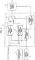
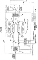
- FIG. 1 is a schematic block diagram showing the whole configuration of an electric motor control apparatus according to Embodiment 1 of this invention.
- numeral 10 designates the electric motor control apparatus, and the brushless motor (hereinbelow, also termed "motor") 5 which includes the windings of the three phases of U-, V- and W-phases is controlled by employing this electric motor control apparatus 10.
- motor brushless motor
- the electric motor control apparatus 10 receives a signal from a motor angle sensor 6 which detects the rotation angle of the motor 5, and it calculates the rotation angle of the motor by a motor rotation angle detecting circuit 21. Besides, the electric motor control apparatus calculates currents flowing through the respective phases of the motor 5, by a current detecting circuit 22.
- a current control means 23 determines a three-phase voltage command in accordance with a torque current command corresponding to the target value of a motor torque, the detection currents of the respective motor phases, and the motor rotation angle.
- a switching element driving circuit 24 subjects the three-phase voltage command determined by the current control means 23, to PWM modulation, and thus commands an inverter 25 to perform switching manipulations.
- the inverter 25 receives switching manipulation signals from the switching element driving circuit 24, thereby to realize the chopper controls of switching elements 61A to 63A and 61B to 63B constituting output arms, and it causes currents to flow through the respective phases of the motor 5, by electric power fed from a battery 11.
- the motor torque is generated by the currents flowing through the respective phases.
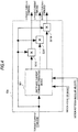
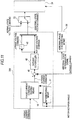
- the current control means 23 include normal-state current controlling means 31 for executing an ordinary control scheme for use in a normal state, abnormal-state current controlling means 30 for use in an abnormal state, an abnormal-state determining means 32, switching means 33, and abnormal phase disconnecting means 34, and it is permitted to switch the two current controlling means 30 and 31.
- the abnormal-state determining means 32 performs the following determination on the basis of the three-phase detection currents fed from the current detecting circuit 22. That is, when the length of a time, for which the magnitude of the detection current of any phase remains above a preset value and for which the detection currents of the other phases remain at or below the preset value, has reached a preset value, the abnormal-state determining means 32 determine that the phase is in an abnormal state. With such an abnormal-state determining means, abnormal states are not determined independently of the respective phases, but they are determined relatively or comprehensively on the basis of the detection currents of the three phases, so that the apprehension of an erroneous determination can be relieved.
- abnormal-state determining means 32 feed an abnormal-state determination signal to the abnormal-state current controlling means 30, the switching means 33 and the abnormal phase disconnecting means 34 in order to notify the presence or absence of any abnormal state and the abnormal phase.
- the abnormal-state current controlling means 30 receive the abnormal-state determination signal from the abnormal-state determining means 32, and it stops its function in a normal state, whereas it performs a control coping with any abnormal phase in a case where the abnormal state has been detected from the certain phase.
- the switching means 33 receives the abnormal-state determination signal from the abnormal-state determining means 32, and it outputs a three-phase normal-state voltage command from the normal-state current controlling means 31 as the three-phase voltage command in a case where the signal of the normal state has been detected, whereas it outputs a three-phase abnormal-state voltage command from the abnormal-state current controlling means 30 as the three-phase voltage command in a case where the signal of the abnormal state has been detected.
- the abnormal phase disconnecting means 34 receives the abnormal-state determination signal from the abnormal-state determining means 32, and it sends a command for stopping the drive of the switching element of the abnormal phase, to the switching element driving circuit 24 in order to disconnect the abnormal phase for the purpose of preventing any overcurrent.
- the normal-state current controlling means 31 may be configured of a known device as shown in, for example, FIG. 17 of International Publication WO 2005/091488 , and it performs an ordinary dq control in the normal state, thereby to realize the generation of a smooth motor torque. Since it is not directly pertinent to the purport of this invention, it shall be omitted from detailed description.
- an abnormal state has occurred in one phase of the motor or the inverter, for example, a case where an abnormal state in which the V-phase of motor wiring, the V-phase of inverter wiring, or the V-phase of wiring connecting the motor and the inverter short-circuits to a wire leading to the minus potential of the battery, or an abnormal state in which the lower switching element of one phase, for example, the V-phase of the output arms of the inverter short-circuits, that is, the grounding of one phase has developed.
- the abnormal-state determining means 32 feeds the abnormal-state determination signal signifying "that the V-phase is abnormal", to the abnormal-state current controlling means 30, the switching means 33 and the abnormal phase disconnecting phase 34 in FIG. 2 .
- the abnormal phase disconnecting means 34 sends the switching element driving circuit 24 a command for stopping the drives of the switching elements 62A and 62B of the V-phase. Owing to the switching element driving circuit 24 which has received this command, the V-phase switching elements 62A and 62B continue their disabled states, and a drive stop state is established therefor.
- the abnormal-state current controlling means 30 is actuated, and the three-phase abnormal-state voltage command is fed to the switching element driving circuit 24 as the three-phase voltage command through the switching means 33.
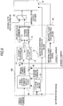
- the abnormal-state current controlling means 30 executes a control scheme shown in FIG. 3 , in order to perform a current control in which the phase having undergone the abnormal state is considered.
- FIG. 3 is a control block-line diagram of the abnormal-state current controlling means 30a in the foregoing case where the V-phase has grounded, and this control scheme shall be called the "grounding-state three-phase individual control" below.
- a phase current command shaping means 50 generates the phase current commands of the respective phases in accordance with the torque current command, the motor rotation angle, and a motor rotation angular velocity obtained by approximately differentiating the motor rotation angle by a differentiating means 51.
- Subtractors 44, 45 and 46 calculate the current deviations of the corresponding phases, respectively, in such a way that the U-, V- and W-phase detection currents obtained by the current detection circuit 22 are subtracted from U-, V- and W-phase current commands.
- subtractors 72 and 73 subtract the current deviation of the V-phase having undergone the abnormal state, from the current deviations of the normal U- and W-phases, and they feed the resulting differences to a U-phase controller 41 and a W-phase controller 43 which are formed of PI controls or the likes.
- adders 74 and 75 add the battery minus voltage value VN of a minus voltage circuit 54 to U- and W-phase commands output from the U-phase controller 41 and the W-phase controller 43, thereby to generate the U- and W-phase voltage commands.
- the abnormal-state controlling means 30a shown in FIG. 3 controls the normal phases individually in accordance with the grounding which has developed in the V-phase.
- the phase current command shaping means 50 has a configuration as shown in FIG. 4 by way of example.
- a unit phase current command generating means 501 determines the unit phase current commands of the respective phases in accordance with the torque current command, the motor rotation angle and the motor rotation angular velocity.
- Multiplication means 502U, 502V and 502W multiply the torque current command and the unit phase current commands of the corresponding phases, respectively, thereby to calculate the phase current commands of the respective phases.
- the unit phase current commands signify the phase current commands of the respective phases at the time when the magnitude of the torque current command is "1".
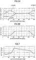
- the relations of the unit phase current commands to the torque current command, the motor rotation angle and the motor rotation angular velocity are, for example, relations shown in FIG. 5 .
- phase current commands When the unit phase current commands are generated by employing the relations of FIG. 5(a) and such phase current commands can be realized as the currents of the respective phase windings, a motor torque waveform as shown in FIG. 5(b) can be obtained.
- This is a command which is intended to output a torque of plus direction being as flat as possible, in the abnormal state where one phase grounds as stated before.
- the motor rotation angle on the axis of abscissas is on the scale of the electrical angle of the motor.
- the motor rotation angular velocity is not used in the calculation of the unit target phase currents, and an example which uses the motor rotation angular velocity will be described in Embodiment 6 later.
- abnormal-state current controlling means 30a is provided with the selective switching element disabling means 53, and the switching element driving circuit 24 can be commanded to temporarily disable the switching elements of the normal phases, in accordance with the motor rotation angle.
- the U-phase switching elements 61A and 61B and the W-phase switching elements 63A and 63B are disabled at the motor rotation angle (0 - 60°) at which currents are to be zeroized, whereby the number of current paths can be decreased.
- FIG. 3 shows the control block-line diagram of the grounding-state three-phase individual control in the case where the abnormal state has occurred in the V-phase, but even in cases where abnormal states have developed in the U- and W-phases, similar grounding-state three-phase individual controls are included in the abnormal-state current controlling means 30a, and they can be switched depending upon the phases in which the abnormal states have occurred.
- the brake torque is a torque which acts in the direction of hampering the rotation of the motor. Even in a case where all the switching elements are disabled, the closed circuit is maintained through the diodes of the normal phases, so that currents based on the induced power flow as shown in FIG. 6 , and the brake torque appears.
- the diodes are usually included in parallel with the respective switching elements within the inverter 25 as shown in FIG. 1 .
- the unit phase current commands and the motor torque waveform are zeroized at the motor rotation angle (0 - 60°).
- the motor rotation angle is a region in which the appearance of the brake torque cannot be prevented, and it is intended to make the currents small even slightly and to make the brake torque small.
- the voltage of the V-phase ought to be made the highest in the angular region.
- the voltage is the lowest value, namely, the minus voltage of the battery on account of the grounding of the V-phase, the generation of the plus torque is impossible. Further, since the closed circuit passing through the grounding place is existent, the brake torque appears, and it is difficult to prevent this brake torque.
- the current commands of the respective phases suitable for the abnormal state are generated by the phase current command shaping means 50, and the control is configured so as to realize the current commands.
- the appearance of the brake torque is suppressed to the utmost, and the torque pulsation can be made small.
- the number of current paths is decreased in the region where the appearance of the brake torque is inevitable, by the selective switching element disabling means 53, so that the brake torque can be minimized.
- the determination of the abnormal state is apprehended to be erroneously done under the influence of noise or the abnormal state of any other phase when, by way of example, the current is controlled to a large current value near the threshold value of determination.
- the abnormal state is determined, not only by estimating the values of the detection currents of the respective phases in terms of the respective absolute values thereof, but also by estimating the values of the detection currents of the three phases relatively, so that the apprehension of the erroneous determination can be relieved.
- the control apparatus of Embodiment 1 of this invention even in the case where the abnormal state has occurred in the wire of the electric motor, the wire of the inverter, or the wire connecting the electric motor and the inverter, and where the overcurrent is apprehended to appear due to the abnormal state, the phase having undergone the abnormal state is disconnected by the abnormal phase disconnecting means 34, and further, using the phases which remain without being disconnected, the current control is continued by the abnormal-state current controlling means 30 replacing the normal-state current controlling means 31, and the respective phases can be individually controlled on the basis of the current commands and voltage commands corresponding to the abnormal state.
- FIG. 9 is a control block-line diagram of an abnormal-state current controlling means 30b according to Embodiment 2 of this invention.
- the phase current command is generated also for the V-phase having undergone the abnormal state, and the control is performed by employing also the V-phase detection current.
- the phase current command shaping means 50 generates only U- and W-phase current commands, U- and W-phase detection currents are respectively subtracted from the U- and W-phase current commands by the subtractors 44 and 46, and the resulting current deviations are fed to the U-phase controller 44 and W-phase controller 46, so as to individually control the respective phases.
- FIG. 10 is a control block-line diagram of an abnormal-state current controlling means 30c according to Embodiment 3 of this invention.
- Embodiment 1 the grounding-state three-phase individual control in FIG. 3 has been employed as the abnormal-state current controlling means, but a similar control is possible even when a control system on dq coordinates is employed.
- One aspect of the control system will now be described as Embodiment 3.
- the abnormal-state current controlling means 30c shown in FIG. 10 is executed instead of the grounding-state three-phase individual control in FIG. 3 as employed in Embodiment 1.
- the control scheme shown in FIG. 10 is substantially similar to the dq control which is employed in the normal state, but it features that the integral terms of d-axis and q-axis controllers are limited.
- FIG. 10 will be described in detail.
- a dq-axis current command shaping means 80 generates d-axis and q-axis current commands in accordance with a torque current command and a motor rotation angle. Subsequently, d-axis and q-axis detection currents output from a two-phase conversion means 86 are respectively subtracted from the d-axis and q-axis current commands by subtractors 83 and 84, thereby to calculate d-axis and q-axis current deviations, which are respectively fed to the d-axis controller 81 and the q-axis controller 82.
- integral term limitation means 114d and 114q are illustrated here, the limitations are similarly attained even when the integral gains 112d and 112q of the integral terms are limited to smaller values. Besides, the integral terms may well be zeroized.
- a three-phase conversion means 85 subjects the d-axis and q-axis voltage commands to three-phase conversion in accordance with the motor rotation angle, thereby to generate U-, V- and W-phase voltage commands.
- the torque current command has been shaped in accordance with the motor rotation angle by the dq-axis current command shaping means 80, the q-axis current command may well be generated without shaping the torque current command, without employing the dq-axis current command shaping means.
- the integral terms are limited, and the q-axis current command is shaped by the dq-axis current command shaping means in some cases, whereby the abnormal-state current controlling means can be configured though the dq control is basically employed.
- the abnormal-state current controlling means which employs the control system on the dq coordinates can also be in another aspect owing to a modification based on the linearity of a control block.
- the integral terms are limited to smaller values than in a normal state, and the d-axis and q-axis current commands are shaped by the dq-axis current command shaping means 80, whereby the appearance of a brake torque can be suppressed more, and a torque pulsation can be made smaller, than in a case where the dq control in the normal state is continued as it is.
- an abnormal state where one phase grounds has been stated in the above embodiments, a similar control is possible, and similar advantages are attained, by making a slight modification also in an abnormal state where one phase shorts-out to a power supply, that is, an abnormal state where one of a motor wire, an inverter wire and a wire connecting the motor and the inverter short-circuits to a wire leading to the plus potential of the battery, or an abnormal state where the upper switching element of one phase of the inverter short-circuits.
- Embodiment 1 concerns the case of the occurrence of an abnormal state where one of a motor wire, an inverter wire and a wire connecting the motor and the inverter, in the V-phase, short-circuits to a wire leading to the minus potential of the battery, or an abnormal state where the lower switching element of the V-phase of the inverter short-circuits, that is, the grounding of one phase, and the abnormal-state current controlling means which corresponds to the abnormal state has been described.
- Embodiment 4 there will be described a case where an abnormal state in which two phases short-circuit therebetween, in other words, interphase short-circuiting has occurred.
- the abnormal-state determining means 32 feeds an abnormal-state determination signal signifying "that the U-phase and the V-phase are abnormal", to the abnormal-state current controlling means 30, the switching means 33 and the abnormal phase disconnecting means 34 in FIG. 2 .
- the abnormal phase disconnecting means 34 sends the switching element driving circuit 24 a command for stopping the drives of the switching elements 61A and 61B of the U-phase. Owing to the switching element driving circuit 24 having received the command, the U-phase switching elements 61A and 61B continue their OFF states, and a drive stop state is established therefor. Either the U-phase or the V-phase may have its drive stopped, and the U-phase is brought into the drive stop state here.
- the abnormal-state current controlling means 30 is actuated by the abnormal-state determination signal, and a three-phase abnormal-state voltage command is fed to the switching element driving circuit 24 through the switching means 33 as a three-phase voltage command.
- the abnormal-state current controlling means 30 executes a control scheme shown in FIG. 11 , in order to perform a current control in which the phases having undergone the abnormal states are considered.
- FIG. 11 is a control block-line diagram of the abnormal-state current controlling means 30d in the case where the U-phase switching elements have been brought into the drive stop states at the occurrence of the UV-phase short-circuiting, and this control scheme shall be called the "UV-phase short-circuiting-state three-phase individual control" below.
- phase current command shaping means 50 in FIG. 11 is similar to that of the means 50 in FIG. 4 , but it may be a configuration which outputs only a W-phase current command.
- the relations of the unit phase current command to a torque current command, a motor rotation angle and a motor rotation angular velocity in a unit phase current command generating means 501 are, for example, relations shown in FIG. 12 .
- Motor rotation angles at which a motor torque becomes zero or can be generated in only a reverse direction are existent in the two-phase short-circuiting state. They are 60 degrees and 240 degrees in FIG. 12 . In the vicinities of the angles, larger currents than in any other angular region are necessitated for generating torques in a forward direction. In the vicinity of each angle, therefore, the phase current command is enlarged to enlarge a phase voltage command, whereby the larger current is caused to flow.
- a torque as shown in FIG. 12(b) can be generated in the normal W-phase.
- the unit phase current command may well be enlarged in proportion to the motor rotation angular velocity.
- the brake torque is a torque which acts in the direction of hampering the rotation of the motor.
- the current commands of the respective phases suitable for the abnormal state are generated by the phase current command shaping means 50, and the control is configured so as to realize the current commands, and hence, the torque based on the normal phase can be enlarged in the vicinity of the motor rotation angle at which the motor torque becomes zero.
- the appearance of the brake torque is suppressed to the utmost, and the torque pulsation can be made small.
- Embodiment 5 there will be described a case where an abnormal state in which one phase of a motor winding short-circuits, that is, one-phase short-circuiting has occurred.
- an abnormal state in which the winding of the U-phase short-circuits, that is, U-phase short-circuiting has occurred will be described below.
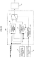
- FIG. 15 is a block diagram showing the configuration of a current control means 23a in Embodiment 5
- the abnormal-state determining means 32 feeds an abnormal-state determination signal signifying "that the U-phase is abnormal", to the abnormal-state current controlling means 30 and the switching means 33 in FIG. 15 .
- the abnormal-state current controlling means 30 is actuated by the abnormal-state determination signal, and a three-phase abnormal-state voltage command is fed to the switching element driving circuit 24 through the switching means 33 as a three-phase voltage command.
- the abnormal-state current controlling means 30 executes a control scheme shown in FIG. 16 , in order to perform a current control in which the phase having undergone the abnormal state is considered.
- FIG. 16 is a control block-line diagram of the abnormal-state current controlling means 30e in the case where the U-phase switching elements have been brought into the drive stop states at the occurrence of the U-phase short-circuiting, and this control scheme shall be called the "U-phase short-circuiting-state three-phase individual control" below.
- the phase current command shaping means 50 generates V- and W-phase current commands in accordance with a torque current command, a motor rotation angle, and a motor rotation angular velocity.
- Subtractors 45 and 46 calculate the current deviations of the corresponding phases, respectively, in such a way that V- and W-phase detection currents obtained by the current detection circuit 22 are subtracted from the V- and W-phase current commands, and they feed the resulting current deviations to a V-phase controller 42 and a W-phase controller 43 which are formed of PI controls or the likes.
- the V- and W-phase controllers 42 and 43 output V- and W-phase voltage commands, respectively.
- a current which can be detected by a U-phase current detecting circuit is the total of currents flowing through a short-circuiting place and a U-phase winding, and a current flowing through the U-phase winding cannot be detected, so that a controller need not be disposed for the U-phase current.
- the V- and W-phase voltage commands have their signs changed and are then added by a subtractor 76, and the resulting sum is output as the U-phase voltage command, in order to control the V- and W-phases at good voltage efficiencies.
- the abnormal-state controlling means 30e shown in FIG. 16 performs the controls individually for the normal phases in accordance with the abnormal state of the U-phase short-circuiting.
- the phase current command shaping means 50 has the configuration in Embodiment 1 as shown in FIG. 4 by way of example. In Embodiment 5, however, the U-phase current command is unnecessary.
- the relations of the unit phase current commands to the torque current command, the motor rotation angle and the motor rotation angular velocity are, for example, relations shown in FIG. 17 .
- phase current commands are generated by employing the relations of FIG. 17(a) and such phase current commands can be realized as the currents of the respective phase windings, a motor torque waveform as shown in FIG. 17(b) can be obtained in the absence of any induced power.
- the current commands in FIG. 17(a) assume large values near motor rotation angles of 60 degrees to 120 degrees and near ones of 240 degrees to 300 degrees.
- the vicinities of the angular regions are regions where the induced powers of the U-phase having short-circuited enlarge, and in order to suppress the influences of brake torque components appearing in the U-phase, the current commands are intended to enlarge the currents of the normal V- and W-phases and to enlarge forward-direction torque components based on the V- and W-phases.
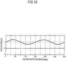
- the motor rotation angle on the axis of abscissas is on the scale of the electrical angle of the motor.
- the brake torque is a torque which acts in the direction of hampering the rotation of the motor.
- the control apparatus in Embodiment 5 of this invention when used, the current commands of the respective phases suitable for the abnormal state are generated by the phase current command shaping means 50, and the control is configured so as to realize the current commands. As in a motor torque waveform shown in FIG. 19 , therefore, the appearance of the brake torque is suppressed to the utmost, and the torque pulsation can be made small.
- the command value may well be further changed in accordance with the motor rotation angular velocity.
- the unit phase current command in FIG. 5 is increased in proportion to the increase of the motor rotation angular velocity.
- the brake torque enlarges in proportion to the motor rotation angular velocity, and hence, the motor torque is enlarged in the angular region where the torque in the plus direction is possible, by the unit phase current command in this embodiment, whereby a motor output can be ensured on the average. Therefore, the motor output can be made less prone to become insufficient.
- FIG. 20 is a control block-line diagram of an abnormal-state current controlling means 30f in Embodiment 7 of this invention, in which the abnormal-state current controlling means 30a shown in FIG. 3 has been modified on the basis of such a linearity.
- FIG. 20 the same reference numerals as in FIG. 3 indicate identical or equivalent parts.
- FIG. 20 has been modified so as to become equivalent to FIG. 3 , owing to the property of linear elements that, in a case where the U-phase controller 41 and the V-phase controller 42 in FIG. 3 are linear and the same, additions/subtractions at the inputs of the elements are respectively equivalent to additions/subtractions at the outputs thereof after the computations.
- FIGS. 21 and 22 show Embodiment 8 of this invention, and they show an example in which the electric motor control apparatus of this invention as illustrated in any of the foregoing embodiments is applied to an electrically-driven power steering apparatus.
- the electrically-driven power steering apparatus includes a three-phase brushless motor, but this invention can be used also for any other apparatus whose power is generated by an electric motor that is driven to rotate by a multiphase alternating current.
- FIG. 21 is a schematic configurational diagram of the electrically-driven power steering apparatus according to Embodiment 8 of this invention.
- a steering force exerted on a steering wheel 1 by a driver not shown is passed through a steering shaft 2 and is transmitted to a rack through a rack-and-pinion gear 12, thereby to steer wheels 3 and 4.
- the brushless motor 5 (hereinbelow, also termed the “motor”) including the windings of the three-phases of U-, V- and W-phases is connected with the steering shaft 2 through a motor reduction gear 7.
- a motor torque (hereinbelow, also termed the "assisting force”) generated by the motor is transmitted to the steering shaft 2 through the motor reduction gear 7, and it relieves the steering force which the driver exerts in a steering operation.
- a torque sensor 8 detects the steering force exerted on the steering shaft 2 in such a way that the driver steers the steering wheel 1.
- a controller unit 9 determines the direction and magnitude of the assisting force which the motor 5 is to bestow, in accordance with the steering force detected by the torque sensor 8, and it controls currents which are to flow from a power source 11 to the motor, in order to generate the assisting force.
- numeral 6 designates a motor angle sensor which detects the rotation angle of the motor.
- FIG. 22 is a block diagram showing the configuration of the controller unit 9.
- the controller unit 9 is configured of a map 20 which calculates a torque current command corresponding to the target value of a motor torque, and an electric motor control apparatus 10.
- the electric motor control apparatus 10 controls the currents flowing through the respective phases of the motor.
- the assisting force based on the motor 5 is generated by the currents.
- the electric motor control apparatus 10 is, for example, one shown in any of Embodiments 1 to 3.
- Embodiment 1 in the abnormal state where one phase grounds, a closed circuit passing through a grounding place is formed, and hence, a motor rotation angle at which the appearance of a brake torque ascribable to the induced power of the motor is inevitable is existent.
- the brake torque is a torque which acts in the direction of hampering the rotation of the motor.
- a control is executed by employing a dq control which is used in a normal state, in the abnormal state of the grounding of one phase, it is not suited to the abnormal state. Therefore, there are the problems that the brake torque is large, and that a torque pulsation becomes large in plus and minus directions.
- the electrically-driven power steering apparatus configured as stated above, in the case of the abnormal state where one phase grounds, the appearance of the brake torque is suppressed to the utmost, and the torque pulsation can be made small. Besides, in a region where the appearance of the brake torque is inevitable, the brake torque can be minimized by a selective switching element disabling means. Therefore, the sense of incompatibility which the driver feels can be relieved.
- the electric motor control apparatus stated above has been one illustrated in any of Embodiments 1-3, but the electric motor control apparatus illustrated in Embodiment 4 may well be employed.
- a closed circuit is formed through a short-circuiting place and the motor windings of the two phases having short-circuited, and hence, a motor rotation angle at which the appearance of a brake torque ascribable to the induced power of the motor is inevitable is existent.
- the brake torque is a torque which acts in the direction of hampering the rotation of the motor. Even in a case where the rotation angular velocity of the motor is zero and where the induced power does not act, a motor rotation angle at which a motor torque becomes zero is existent.
- the induced power between the two short-circuiting phases is especially large, and a current needs to be enlarged for the purpose of canceling the brake torque ascribable to the induced power. Since, however, the current which can be caused to flow has an upper limit ordinarily, it is difficult to suppress the appearance of the brake torque.
- Embodiment 5 may well be employed instead of employing the electric motor control apparatus illustrated in any of Embodiments 1 to 4, A case where the abnormal state of one-phase short-circuiting has occurred, will be stated below.
- the brake torque is a torque which acts in the direction of hampering the rotation of the motor.
- a motor output can be ensured on the average by enlarging a motor torque in an angular region in which the torque in the plus direction is possible, so that a sense of incompatibility which the driver feels can be relieved.
Landscapes
- Engineering & Computer Science (AREA)
- Power Engineering (AREA)
- Chemical & Material Sciences (AREA)
- Combustion & Propulsion (AREA)
- Transportation (AREA)
- Mechanical Engineering (AREA)
- Control Of Ac Motors In General (AREA)
- Control Of Motors That Do Not Use Commutators (AREA)
Applications Claiming Priority (1)
| Application Number | Priority Date | Filing Date | Title |
|---|---|---|---|
| PCT/JP2006/308323 WO2007129359A1 (ja) | 2006-04-20 | 2006-04-20 | 電動機制御装置 |
Publications (3)
| Publication Number | Publication Date |
|---|---|
| EP2009782A1 EP2009782A1 (en) | 2008-12-31 |
| EP2009782A4 EP2009782A4 (en) | 2012-11-14 |
| EP2009782B1 true EP2009782B1 (en) | 2021-06-23 |
Family
ID=38667480
Family Applications (1)
| Application Number | Title | Priority Date | Filing Date |
|---|---|---|---|
| EP06745504.8A Expired - Fee Related EP2009782B1 (en) | 2006-04-20 | 2006-04-20 | Electric motor control apparatus |
Country Status (6)
| Country | Link |
|---|---|
| US (1) | US7990093B2 (ja) |
| EP (1) | EP2009782B1 (ja) |
| JP (1) | JP4772116B2 (ja) |
| KR (2) | KR101139146B1 (ja) |
| CN (1) | CN101401295B (ja) |
| WO (1) | WO2007129359A1 (ja) |
Families Citing this family (42)
| Publication number | Priority date | Publication date | Assignee | Title |
|---|---|---|---|---|
| CN101667808B (zh) * | 2006-04-20 | 2012-10-17 | 株式会社电装 | 多相旋转电机的控制系统 |
| JP2009131043A (ja) * | 2007-11-22 | 2009-06-11 | Hitachi Ltd | モータ制御装置 |
| DE102008000146A1 (de) * | 2008-01-25 | 2009-07-30 | Zf Friedrichshafen Ag | Verfahren und Anordnung zum Ansteuern eines elektrischen Antriebes |
| JP5119991B2 (ja) * | 2008-03-11 | 2013-01-16 | 株式会社ジェイテクト | 電動パワーステアリング装置 |
| JP5115344B2 (ja) * | 2008-06-11 | 2013-01-09 | 株式会社デンソー | 車載電子制御装置及び操舵制御システム |
| US8125747B2 (en) * | 2009-03-16 | 2012-02-28 | Honeywell International Inc. | Method for mitigating negative sequence effect resulting from non-symmetrical short circuit failure of synchronous electric machine based systems |
| DE102010001241A1 (de) | 2009-04-01 | 2010-10-07 | Robert Bosch Gmbh | Elektronisch kommutierter Elektromotor mit einer Notlaufeigenschaft |
| DE112009004758T5 (de) * | 2009-05-08 | 2012-12-20 | Mitsubishi Electric Corporation | Motor-Steuervorrichtung |
| JP5402414B2 (ja) | 2009-09-02 | 2014-01-29 | 日本精工株式会社 | 電動パワーステアリング装置 |
| US8476853B2 (en) * | 2009-09-04 | 2013-07-02 | Black & Decker Inc. | Redundant overspeed protection for power tools |
| JP4831503B2 (ja) * | 2009-09-30 | 2011-12-07 | 株式会社デンソー | 多相回転機の制御装置、および、これを用いた電動パワーステアリング装置 |
| JP5387989B2 (ja) * | 2009-12-25 | 2014-01-15 | 株式会社デンソー | 電動機駆動装置、および、これを用いた電動パワーステアリング装置 |
| JP5447645B2 (ja) * | 2010-03-03 | 2014-03-19 | 株式会社安川電機 | インバータ装置及びその制御方法 |
| KR101422380B1 (ko) * | 2010-03-23 | 2014-07-22 | 콘티넨탈 오토모티브 게엠베하 | 브러시리스 전기 모터를 동작시키는 방법 |
| JP5073018B2 (ja) * | 2010-07-02 | 2012-11-14 | 三菱電機株式会社 | 電力変換装置 |
| CN102582679B (zh) * | 2011-01-07 | 2015-06-17 | 本田技研工业株式会社 | 电动助力转向装置 |
| DE102011085657A1 (de) | 2011-11-03 | 2013-05-08 | Robert Bosch Gmbh | Verfahren und Vorrichtung zum Betreiben einer elektronisch kommutierten elektrischen Maschine in einem Fehlerfall |
| WO2013111327A1 (ja) | 2012-01-27 | 2013-08-01 | 三菱電機株式会社 | モータ制御装置および電動パワーステアリング装置 |
| JP5436592B2 (ja) | 2012-02-07 | 2014-03-05 | 三菱電機株式会社 | モータ制御装置、モータ制御装置に適用される電流制御方法、およびモータ制御装置を用いた電動パワーステアリング装置 |
| CN103378778B (zh) * | 2012-04-28 | 2016-01-20 | 广东高标电子科技有限公司 | 一种电动车、无刷直流电机及其驱动控制系统 |
| US9283852B2 (en) * | 2012-05-09 | 2016-03-15 | Schneider Electric USA, Inc. | Diagnostic receptacle for electric vehicle supply equipment |
| JP6073692B2 (ja) * | 2013-01-23 | 2017-02-01 | ルネサスエレクトロニクス株式会社 | モータ駆動制御装置およびその動作方法 |
| JP6026899B2 (ja) * | 2013-01-28 | 2016-11-16 | 日立オートモティブシステムズ株式会社 | モータ制御システム |
| JP5803951B2 (ja) * | 2013-02-08 | 2015-11-04 | 株式会社デンソー | 回転電機駆動システム |
| JP6194615B2 (ja) * | 2013-04-04 | 2017-09-13 | 株式会社ジェイテクト | モータ制御装置 |
| KR101566590B1 (ko) * | 2013-11-29 | 2015-11-13 | 엘에스산전 주식회사 | 인버터 제어장치 |
| JP6220696B2 (ja) * | 2014-02-19 | 2017-10-25 | 日立オートモティブシステムズ株式会社 | 電動モータの駆動制御装置 |
| JP6362349B2 (ja) * | 2014-02-19 | 2018-07-25 | 日立オートモティブシステムズ株式会社 | 電動モータの駆動制御装置 |
| US9876458B2 (en) | 2014-03-19 | 2018-01-23 | Mitsubishi Electric Corporation | Control device for AC rotating machine and electric power steering device |
| JP6553097B2 (ja) * | 2014-06-23 | 2019-07-31 | ディーエイチ テクノロジーズ デベロップメント プライベート リミテッド | イオン移動度分光計電力供給源のためのクロストーク補償 |
| WO2016148715A1 (en) * | 2015-03-19 | 2016-09-22 | Schlumberger Canada Limited | Submersible multiphase electric motor systems |
| EP3297763A4 (en) * | 2015-05-22 | 2019-02-20 | Callicoat, Clay | LIQUID PRODUCT PUMPING DEVICES, SYSTEMS AND METHOD OF USE THEREOF |
| JP2017169405A (ja) * | 2016-03-17 | 2017-09-21 | 株式会社ジェイテクト | モータ制御装置及び操舵制御装置 |
| US10322748B2 (en) * | 2016-09-23 | 2019-06-18 | Jtekt Corporation | Motor controller and steering device |
| JP6838251B2 (ja) * | 2017-10-11 | 2021-03-03 | 日立Astemo株式会社 | モータ駆動制御装置及びモータ電力供給線の異常検知方法 |
| US10753976B2 (en) * | 2017-10-13 | 2020-08-25 | Schweitzer Engineering Laboratories, Inc. | Detection of transient high torque events associated with rotating machinery in electric power systems |
| US10340827B2 (en) * | 2017-11-06 | 2019-07-02 | Steering Solutions Ip Holding Corporation | Fault tolerant current measurement in motor control systems |
| DE102018133248B4 (de) * | 2018-01-05 | 2022-08-11 | Panasonic Intellectual Property Management Co., Ltd. | Motorsteuervorrichtung und Steuerverfahren für Motorsteuervorrichtung |
| FR3078050B1 (fr) * | 2018-02-22 | 2020-06-26 | Jtekt Europe | Procede de compensation d’un couple frein lors d’une defaillance de type court-circuit dans l’onduleur d’alimentation d’un moteur d’assistance |
| CN113261199B (zh) * | 2018-12-28 | 2024-03-19 | 日立安斯泰莫株式会社 | 马达控制装置 |
| CN115516758A (zh) | 2020-05-13 | 2022-12-23 | 三菱电机株式会社 | 交流旋转电机的控制装置 |
| EP4365061A1 (en) | 2021-06-28 | 2024-05-08 | Mitsubishi Electric Corporation | Autonomous driving assistance device |
Family Cites Families (16)
| Publication number | Priority date | Publication date | Assignee | Title |
|---|---|---|---|---|
| JP3291390B2 (ja) * | 1994-02-07 | 2002-06-10 | 三菱電機株式会社 | インバータの故障検出方式 |
| JPH11220884A (ja) * | 1998-02-03 | 1999-08-10 | Hitachi Ltd | 自励式変換器の保護装置及び可変速発電電動機システムの制御装置並びに自己消弧形変換器の制御装置 |
| JP3661572B2 (ja) * | 2000-07-18 | 2005-06-15 | 日産自動車株式会社 | インバーターの電流センサー診断装置 |
| JP2003008099A (ja) | 2001-06-21 | 2003-01-10 | Matsushita Electric Ind Co Ltd | 磁気検出素子 |
| JP2003081099A (ja) | 2001-09-07 | 2003-03-19 | Koyo Seiko Co Ltd | 電動パワーステアリング装置 |
| JP2003259654A (ja) | 2002-03-05 | 2003-09-12 | Toshiba Corp | 電力変換装置 |
| JP4097494B2 (ja) | 2002-09-25 | 2008-06-11 | 独立行政法人科学技術振興機構 | 三相交流モータ駆動用インバータ装置 |
| JP2005051901A (ja) | 2003-07-31 | 2005-02-24 | Fuji Electric Device Technology Co Ltd | 電力変換装置 |
| JP4066914B2 (ja) * | 2003-08-25 | 2008-03-26 | 富士電機システムズ株式会社 | モータ駆動制御装置 |
| JP2005153570A (ja) * | 2003-11-20 | 2005-06-16 | Favess Co Ltd | 電動パワーステアリング装置 |
| JP2005218215A (ja) * | 2004-01-29 | 2005-08-11 | Nsk Ltd | Pmモータの駆動方法および温度推定方法 |
| CN100490302C (zh) * | 2004-03-19 | 2009-05-20 | 三菱电机株式会社 | 电动机控制装置 |
| JP4506263B2 (ja) * | 2004-04-30 | 2010-07-21 | 日本精工株式会社 | 電動パワーステアリング装置の制御装置 |
| JP4701767B2 (ja) * | 2005-03-18 | 2011-06-15 | トヨタ自動車株式会社 | 電源装置 |
| US7759888B2 (en) * | 2005-04-15 | 2010-07-20 | Hitachi, Ltd. | AC motor controller |
| US7977963B2 (en) * | 2009-07-21 | 2011-07-12 | GM Global Technology Operations LLC | Methods, systems and apparatus for detecting abnormal operation of an inverter sub-module |
-
2006
- 2006-04-20 US US12/279,859 patent/US7990093B2/en active Active
- 2006-04-20 CN CN2006800538022A patent/CN101401295B/zh not_active Expired - Fee Related
- 2006-04-20 EP EP06745504.8A patent/EP2009782B1/en not_active Expired - Fee Related
- 2006-04-20 WO PCT/JP2006/308323 patent/WO2007129359A1/ja active Application Filing
- 2006-04-20 KR KR1020117007047A patent/KR101139146B1/ko active IP Right Grant
- 2006-04-20 JP JP2008514309A patent/JP4772116B2/ja not_active Expired - Fee Related
- 2006-04-20 KR KR1020087024378A patent/KR101040890B1/ko active IP Right Grant
Non-Patent Citations (1)
| Title |
|---|
| None * |
Also Published As
| Publication number | Publication date |
|---|---|
| KR101040890B1 (ko) | 2011-06-16 |
| CN101401295B (zh) | 2013-07-17 |
| KR20080108121A (ko) | 2008-12-11 |
| WO2007129359A1 (ja) | 2007-11-15 |
| CN101401295A (zh) | 2009-04-01 |
| KR20110036650A (ko) | 2011-04-07 |
| JP4772116B2 (ja) | 2011-09-14 |
| US20090021207A1 (en) | 2009-01-22 |
| EP2009782A1 (en) | 2008-12-31 |
| JPWO2007129359A1 (ja) | 2009-09-17 |
| KR101139146B1 (ko) | 2012-04-26 |
| EP2009782A4 (en) | 2012-11-14 |
| US7990093B2 (en) | 2011-08-02 |
Similar Documents
| Publication | Publication Date | Title |
|---|---|---|
| EP2009782B1 (en) | Electric motor control apparatus | |
| US8981704B2 (en) | Motor controller and electric power steering device using the same | |
| US8569981B2 (en) | Motor drive and electric power steering apparatus using the same | |
| EP2725705B1 (en) | Motor control device and electric power steering device using same | |
| US8710775B2 (en) | Electric power steering apparatus | |
| JP5621598B2 (ja) | モータ制御装置及び電動パワーステアリング装置 | |
| US8983727B2 (en) | Steering control apparatus | |
| EP2625088B1 (en) | Electric power steering apparatus | |
| JP5653516B2 (ja) | モータ制御装置 | |
| EP1557940B1 (en) | Motor controller | |
| JP2006044338A (ja) | 電動パワーステアリング装置 | |
| US9461568B2 (en) | Motor control device and steering device for vehicle | |
| EP3020615B1 (en) | Electric power steering device | |
| WO2006132268A1 (ja) | 電動パワーステアリング装置 | |
| JP2006256550A (ja) | 電動パワーステアリング装置 | |
| WO2005057774A1 (ja) | モータ制御装置およびそれを用いた車両用操舵装置 | |
| JP7131510B2 (ja) | モータ制御装置 | |
| CN110574281B (zh) | 电动机的控制装置及电动助力转向系统 | |
| CN106961237B (zh) | 电机控制装置以及包括电机控制装置的电动力转向装置 | |
| JP2012006463A (ja) | 電動パワーステアリング装置 | |
| JP2012147531A (ja) | 電動パワーステアリング装置 | |
| JP4644013B2 (ja) | 電動パワーステアリング装置 | |
| JP2005160221A (ja) | 電動パワーステアリング装置の制御装置 | |
| JP5933316B2 (ja) | モータ制御装置、モータ制御方法および電動パワーステアリング装置 |
Legal Events
| Date | Code | Title | Description |
|---|---|---|---|
| PUAI | Public reference made under article 153(3) epc to a published international application that has entered the european phase |
Free format text: ORIGINAL CODE: 0009012 |
|
| 17P | Request for examination filed |
Effective date: 20081010 |
|
| AK | Designated contracting states |
Kind code of ref document: A1 Designated state(s): AT BE BG CH CY CZ DE DK EE ES FI FR GB GR HU IE IS IT LI LT LU LV MC NL PL PT RO SE SI SK TR |
|
| AX | Request for extension of the european patent |
Extension state: AL BA HR MK YU |
|
| RIN1 | Information on inventor provided before grant (corrected) |
Inventor name: INOUE, NORIYUKI Inventor name: FUJIMOTO, CHIAKI Inventor name: TSUTSUMI, KAZUMICHI Inventor name: KIFUKU, TAKAYUKI Inventor name: KIMATA, MASAHIRO Inventor name: KEZOBO, ISAO |
|
| DAX | Request for extension of the european patent (deleted) | ||
| RBV | Designated contracting states (corrected) |
Designated state(s): DE FR |
|
| RIN1 | Information on inventor provided before grant (corrected) |
Inventor name: INOUE, NORIYUKI Inventor name: FUJIMOTO, CHIAKI Inventor name: TSUTSUMI, KAZUMICHI Inventor name: KIFUKU, TAKAYUKI Inventor name: KIMATA, MASAHIRO Inventor name: KEZOBO, ISAO |
|
| A4 | Supplementary search report drawn up and despatched |
Effective date: 20121016 |
|
| RIC1 | Information provided on ipc code assigned before grant |
Ipc: H02P 27/06 20060101ALI20121010BHEP Ipc: H02P 21/00 20060101AFI20121010BHEP Ipc: H02P 27/04 20060101ALI20121010BHEP |
|
| 17Q | First examination report despatched |
Effective date: 20160720 |
|
| STAA | Information on the status of an ep patent application or granted ep patent |
Free format text: STATUS: EXAMINATION IS IN PROGRESS |
|
| GRAP | Despatch of communication of intention to grant a patent |
Free format text: ORIGINAL CODE: EPIDOSNIGR1 |
|
| STAA | Information on the status of an ep patent application or granted ep patent |
Free format text: STATUS: GRANT OF PATENT IS INTENDED |
|
| INTG | Intention to grant announced |
Effective date: 20201126 |
|
| GRAS | Grant fee paid |
Free format text: ORIGINAL CODE: EPIDOSNIGR3 |
|
| GRAA | (expected) grant |
Free format text: ORIGINAL CODE: 0009210 |
|
| STAA | Information on the status of an ep patent application or granted ep patent |
Free format text: STATUS: THE PATENT HAS BEEN GRANTED |
|
| AK | Designated contracting states |
Kind code of ref document: B1 Designated state(s): DE FR |
|
| REG | Reference to a national code |
Ref country code: DE Ref legal event code: R096 Ref document number: 602006060094 Country of ref document: DE |
|
| REG | Reference to a national code |
Ref country code: DE Ref legal event code: R097 Ref document number: 602006060094 Country of ref document: DE |
|
| PLBE | No opposition filed within time limit |
Free format text: ORIGINAL CODE: 0009261 |
|
| STAA | Information on the status of an ep patent application or granted ep patent |
Free format text: STATUS: NO OPPOSITION FILED WITHIN TIME LIMIT |
|
| 26N | No opposition filed |
Effective date: 20220324 |
|
| PGFP | Annual fee paid to national office [announced via postgrant information from national office to epo] |
Ref country code: FR Payment date: 20220308 Year of fee payment: 17 |
|
| PGFP | Annual fee paid to national office [announced via postgrant information from national office to epo] |
Ref country code: DE Payment date: 20220302 Year of fee payment: 17 |
|
| P01 | Opt-out of the competence of the unified patent court (upc) registered |
Effective date: 20230512 |
|
| REG | Reference to a national code |
Ref country code: DE Ref legal event code: R119 Ref document number: 602006060094 Country of ref document: DE |
|
| PG25 | Lapsed in a contracting state [announced via postgrant information from national office to epo] |
Ref country code: FR Free format text: LAPSE BECAUSE OF NON-PAYMENT OF DUE FEES Effective date: 20230430 Ref country code: DE Free format text: LAPSE BECAUSE OF NON-PAYMENT OF DUE FEES Effective date: 20231103 |