EP2006229A2 - Blattglättungsvorrichtung und Bilderzeugungsvorrichtung - Google Patents
Blattglättungsvorrichtung und Bilderzeugungsvorrichtung Download PDFInfo
- Publication number
- EP2006229A2 EP2006229A2 EP08252098A EP08252098A EP2006229A2 EP 2006229 A2 EP2006229 A2 EP 2006229A2 EP 08252098 A EP08252098 A EP 08252098A EP 08252098 A EP08252098 A EP 08252098A EP 2006229 A2 EP2006229 A2 EP 2006229A2
- Authority
- EP
- European Patent Office
- Prior art keywords
- roller
- transportation path
- sheet
- moving unit
- moving
- Prior art date
- Legal status (The legal status is an assumption and is not a legal conclusion. Google has not performed a legal analysis and makes no representation as to the accuracy of the status listed.)
- Granted
Links
Images


Classifications
-
- B—PERFORMING OPERATIONS; TRANSPORTING
- B65—CONVEYING; PACKING; STORING; HANDLING THIN OR FILAMENTARY MATERIAL
- B65H—HANDLING THIN OR FILAMENTARY MATERIAL, e.g. SHEETS, WEBS, CABLES
- B65H29/00—Delivering or advancing articles from machines; Advancing articles to or into piles
-
- G—PHYSICS
- G03—PHOTOGRAPHY; CINEMATOGRAPHY; ANALOGOUS TECHNIQUES USING WAVES OTHER THAN OPTICAL WAVES; ELECTROGRAPHY; HOLOGRAPHY
- G03G—ELECTROGRAPHY; ELECTROPHOTOGRAPHY; MAGNETOGRAPHY
- G03G15/00—Apparatus for electrographic processes using a charge pattern
- G03G15/65—Apparatus which relate to the handling of copy material
- G03G15/6555—Handling of sheet copy material taking place in a specific part of the copy material feeding path
- G03G15/6573—Feeding path after the fixing point and up to the discharge tray or the finisher, e.g. special treatment of copy material to compensate for effects from the fixing
- G03G15/6576—Decurling of sheet material
-
- B—PERFORMING OPERATIONS; TRANSPORTING
- B65—CONVEYING; PACKING; STORING; HANDLING THIN OR FILAMENTARY MATERIAL
- B65H—HANDLING THIN OR FILAMENTARY MATERIAL, e.g. SHEETS, WEBS, CABLES
- B65H2301/00—Handling processes for sheets or webs
- B65H2301/50—Auxiliary process performed during handling process
- B65H2301/51—Modifying a characteristic of handled material
- B65H2301/512—Changing form of handled material
- B65H2301/5125—Restoring form
- B65H2301/51256—Removing waviness or curl, smoothing
-
- B—PERFORMING OPERATIONS; TRANSPORTING
- B65—CONVEYING; PACKING; STORING; HANDLING THIN OR FILAMENTARY MATERIAL
- B65H—HANDLING THIN OR FILAMENTARY MATERIAL, e.g. SHEETS, WEBS, CABLES
- B65H2801/00—Application field
- B65H2801/03—Image reproduction devices
- B65H2801/06—Office-type machines, e.g. photocopiers
-
- G—PHYSICS
- G03—PHOTOGRAPHY; CINEMATOGRAPHY; ANALOGOUS TECHNIQUES USING WAVES OTHER THAN OPTICAL WAVES; ELECTROGRAPHY; HOLOGRAPHY
- G03G—ELECTROGRAPHY; ELECTROPHOTOGRAPHY; MAGNETOGRAPHY
- G03G2215/00—Apparatus for electrophotographic processes
- G03G2215/00362—Apparatus for electrophotographic processes relating to the copy medium handling
- G03G2215/00535—Stable handling of copy medium
- G03G2215/00662—Decurling device
Definitions
- a toner image carrying surface of the sheet touches a heating source member such as a heating roller and heat and pressure are used to cause the toner to melt and penetrate the sheet, thus fixing the toner on the sheet.
- a heating source member such as a heating roller and heat and pressure are used to cause the toner to melt and penetrate the sheet, thus fixing the toner on the sheet.
- moisture of the sheet that is subjected to fixing evaporates, thus causing a change in a moisture content percentage of a sheet surface that is touching the heating source member and a back surface.
- Change in the moisture content percentage causes occurrence of warping in a thickness direction, in other words, a rolling tendency called a curl.
- a sheet decurling device that decurls a recording sheet, including a first transportation path and a second transportation path that can selectively link to a main transportation path of the recording sheet; a first roller arranged between the first transportation path and the second transportation path; a second roller capable of making contact with the first roller across the first transportation path; a third roller capable of making contact with the first roller across the second transportation path; a moving unit that includes the first transportation path, the second transportation path, the first roller, the second roller, the third roller, and a driving source that drives the first roller, and that moves its position such that the first transportation path and the second transportation path are selectively linked to the main transportation path; a moving position detecting unit that detects a position of the moving unit; and a mechanism that varies, upon the moving unit moving to a position at which either one of the first transportation path and the second transportation path is linked to the main transportation path, a pressing force of the second roller or the third roller with respect to the first roller.
- an image forming apparatus including a sheet decurling device that decurls a recording sheet.
- the sheet decurling device includes a first transportation path and a second transportation path that can selectively link to a main transportation path of the recording sheet; a first roller arranged between the first transportation path and the second transportation path; a second roller capable of making contact with the first roller across the first transportation path; a third roller capable of making contact with the first roller across the second transportation path; a moving unit that includes the first transportation path, the second transportation path, the first roller, the second roller, the third roller, and a driving source that drives the first roller, and that moves its position such that the first transportation path and the second transportation path are selectively linked to the main transportation path; a moving position detecting unit that detects a position of the moving unit; and a mechanism that varies, upon the moving unit moving to a position at which either one of the first transportation path and the second transportation path is linked to the main transportation path, a pressing force of the second roller or
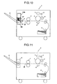
- FIG. 11 is a schematic of an overview of an image forming apparatus P that uses a common electronographic method and the sheet decurling device.
- an optical unit 3 Based on a principle of a common electronographic printer, after a charger 1 has uniformly charged a photosensitive drum 2, an optical unit 3 emits light on a surface of the photosensitive drum 2.
- a developer 4 adheres a toner, which is reversely charged with respect to the photosensitive drum 2, on the electrostatic latent image to form a visual image.
- a toner image, which is formed on the surface of the photosensitive drum 2 is transferred by a transfer unit 5 onto a sheet that is a recording member and that is transported via a string of transportation paths from a sheet feeder 6.
- the sheet is transported to a discharging unit 8.
- the sheet decurling device is necessitated in the vicinity of a G portion on a transportation path from the fixing unit 7 of the printer towards the discharging unit 8. Due to this, when the sheet, which is curled at the time of passing the fixing unit 7 and moving towards the discharging unit 8, passes the sheet decurling device, the curl is corrected by the sheet decurling device.
- a sheet decurling device 1000 includes a moving unit 100 such that a first transportation path 101 and a second transportation path 102, which are internally included, can be selectively linked to a main path MP.
- the sheet decurling device 1000 shown in Fig. 10 is internally embedded into the image forming apparatus.
- the sheet decurling device according to the present invention can also be arranged separately from the image forming apparatus.
- the sheet decurling device can be arranged at an entrance of a sorter, a collator, or a stacking device that are used in a post process of a recording sheet.
- Fig. 1 is a schematic for explaining an internal structure of the moving unit 100.
- the moving unit 100 includes a first roller 103, a second roller 104, and a third roller 105.
- the first roller 103 is arranged between the first transportation path 101 and the second transportation path 102 such that a portion of a peripheral surface of the first roller 103 is exposed to the first transportation path 101 and the second transportation path 102.
- the second roller 104 can touch the first roller 103 across the first transportation path 101.
- the third roller 105 can touch the first roller 103 across the second transportation path 102.
- the first roller 103 is formed of an elastic body such as sponge rubber.
- the second roller 104 and the third roller 105 are metal rollers formed of stainless steel.
- the second roller 104 is used as an upper pressure roller that is positioned on the upper side of the first roller 103 and the third roller 105 is used as a lower pressure roller that is positioned on the lower side of the first roller 103.
- the second roller 104 and the third roller 105 are pressed against the first roller 103, thus enabling the second roller 104 and the third roller 105 to function as decurling rollers that correct the curl by causing the recording sheet to roll in a reverse direction of a curl direction.
- the second roller 104 and the third roller 105 are opposite to each other across the first roller 103 and are positioned such that a line L, which joins touching positions of the second roller 104 and the third roller 105 with respect to the first roller 103, is perpendicular to progressing directions of the sheet that enters from the first transportation path 101 and the second transportation path 102 (directions indicated by the arrows A and B respectively). Due to this, the recording sheet, which enters inside the sheet decurling device 1000, can enter in a tangential direction with respect to the first roller 103, the second roller 104, and the third roller 105, and can receive pressure from the first roller 103, the second roller 104, and the third roller 105 most efficiently.
- the moving unit 100 can move in a perpendicular direction.
- a driving pulley 201A is arranged on the motor 201 that is arranged as the elevatably driving source on the elevating unit 200.
- An elevating screw 205 which is integrated with a driven pulley 204, can link with the driving pulley 201A via a belt 203.
- the elevating screw 205 is fitted to a not shown nut inside a side wall 100A that is integrated with the upper portion of the moving unit 100.
- the moving unit 100 is elevated according to a rotation direction of the elevating screw 205.
- An elevation position of the moving unit 100 is detected by a position detecting sensor PS (see Fig. 2 ) that uses an optical sensor that can detect light interception upon entry of a sector member that is arranged on a side of the moving unit 100.
- the moving unit 100 stops at a predetermined position.
- An elevation amount of the moving unit 100 is equivalent to a distance till a position that enables any one of the first transportation path 101 and the second transportation path 102 to link to the main transportation path MP.
- the idle gears IG1 to IG3 treat as a first level, a driving gear 202A that is fixed to an output shaft of the motor 202.
- a decurler roller gear 103A which is fixed to a rotating shaft 103B of the first roller 103, meshes with the idle gear IG3 of the last level.
- the sheet decurling device includes a structure that changes a touching force of any one of the second roller 104 and the third roller 105 with respect to the first roller 103 when any one of the first transportation path 101 and the second transportation path 102 moves to a position that links to the main transportation path MP.
- the structure and working of the structure are explained next with reference to Fig. 4 onwards.
- Fig. 4 is a schematic for explaining a principle that is used for causing the moving unit 100 at the elevation position to change a pressurizing force of the second roller 104 and the third roller 105 with respect to the first roller 103.
- rotating shafts 103B, 104A, and 105A, of the first roller 103, the second roller 104, and the third roller 105 respectively, are inserted into the side wall 100A of the moving unit 100.
- an axial end of the rotating shaft 103B of the first roller 103 is inserted into a long hole 200Al that is formed in a side wall 200A of the elevating unit 200 that is arranged separately from the moving unit 100.
- the long hole 200A1 which is formed in the side wall 200A, is arranged along a moving direction of the moving unit 100.
- the rotating shaft 103B of the first roller 103 is inserted into a freely-moving supporting unit 100A1 that is formed as a long hole along the moving direction of the moving unit 100.
- the rotating shafts 104A and 105A of the second roller 104 and the third roller 105 respectively are rotatably supported via a shaft bearing SB.
- the shaft bearing SB does not cause the rotating shafts 104A and 105A to move in the moving direction of the moving unit 100.
- the second roller 104 and the third roller 105 move independently with respect to the first roller 103, and depending on the moving direction, the pressurizing force of any one of the second roller 104 and the third roller 105 with respect to the first roller 103 increases.
- the rotating shaft 103B of the first roller 103 is pressed against an end, in other words, the upper end, of the long hole 200A1, and the moving unit 100 continues to be elevated further, the supporting unit 100A1 can cause the moving unit 100 to move without interfering with the first roller 103. Due to this, the third roller 105, which is positioned in a peripherally downward direction with respect to the first roller 103, is pressed against the first roller 103 and the pressurizing force of the third roller 105 with respect to the first roller 103 increases.
- Fig. 5 is a schematic of the driving path when the moving unit 100 is elevated and the second roller 104 is touching the first roller 103.
- Fig. 6 is a schematic of the driving path when the moving unit 100 has moved downward and the third roller 105 is touching the first roller 103.
- simply setting a rotation direction of the motor 202 to one direction enables to establish a meshing relation between the idle gears IG1 to IG3 and the decurler roller gear 103A that are opposite to each other when the moving unit 100 is elevated, thus enabling to set the rotation direction of the first roller 103 such that the first roller 103 can eject the sheet using the first transportation path 101 and the second transportation path 102.
- using the structure mentioned earlier enables to set a position such that any one of the first transportation path 101 and the second transportation path 102 links to the main transportation path MP according to the moving direction of the moving unit 100.
- Figs. 7 and 8 are schematics for explaining a relation among the moving unit 100, the main transportation path MP, and an ejection path (for the sake of convenience, the ejection path is indicated by a symbol EX) that is turned towards the discharging unit 8.
- the ejection path when the moving unit 100 is elevated is shown in Fig. 7 .
- the ejection path when the moving unit 100 has moved downwards is shown in Fig. 8 .
- the moving unit 100 is elevated and a condition shown in Fig. 7 is set.
- the second transportation path 102 in the moving unit 100 links to the main transportation path MP and based on the operation explained with reference to Fig. 4 , the pressurizing force of the third roller 105 with respect to the first roller 103 increases. Due to this, the recording sheet, which is sandwich-transported by the first roller 103 and the third roller 105, is subjected to decurling in an opposite direction of the curl direction of the curl that occurs in the recording sheet itself and the curl is corrected.
- the moving unit 100 moves downward and a condition shown in Fig. 8 is set.
- the first transportation path 101 in the moving unit 100 continues to the main transportation path MP and the pressurizing force of the second roller 104 with respect to the first roller 103 increases. Due to this, the recording sheet, which is sandwich-transported by the first roller 103 and the second roller 104, is subjected to decurling in the opposite direction of the curl direction of the curl that occurs in the recording sheet itself and the curl is corrected.
- a configuration of the first transportation path 101 and the second transportation path 102 is linked to the ejection path EX. Due to this, the recording sheet, which is sandwich-transported among the first roller 103, the second roller 104, and the third roller 105, is ejected normally without occurrence of an ejection defect.
- an elevation setting of the moving unit 100 can be carried out to set the condition that can carry out curl correction.
- the elevation setting of the moving unit 100 can also be set by prior estimating the curl direction. A structure which prior estimates the curl direction is explained below.
- rotation control of the motor 201 which is a movably driving source of the moving unit 100, can also be carried out.
- Fig. 9 is a functional block diagram of a controller 300 that is used for rotation control of the motor 201.
- a controller which executes an image forming sequence, is used as the controller 300.
- An operation panel 301 which enables specification of the sheet size, a temperature and humidity sensor 302, and an image area ratio-input unit 303 are connected to an input side of the controller 300.
- the driving pulley 201A of the motor 201 is connected to an output side of the controller 300.
- the image area ratio-input unit 303 Based on pixel signals from a scanner or received image signals, the image area ratio-input unit 303, which is connected to the controller 300, calculates an image area ratio with respect to the sheet size.
- the controller 300 Based on input data such as the sheet size, the temperature and humidity, or the image area ratio, the controller 300 prior estimates the curl direction of the curl that occurs in the recording sheet and sets a selection of the first transportation path 101 and the second transportation path 102 and the rotation direction of the motor 201 such that the recording sheet can be subjected to decurling in the opposite direction of the curl direction.
- the curl direction and the curl amount are affected by a moisture content percentage of the recording sheet. Testing an evaporation rate of the moisture content due to heating during fixing enables to prior estimate the curl direction and the curl amount to some extent.
- the sheet size can also include a sheet thickness.
- a relation between the sheet size and the image area ratio that are affected by the evaporation rate of the moisture is mapped. Further, a relation between the temperature and humidity and the evaporation rate of the moisture content is also mapped.
- a correspondence is established between each input data and the evaporation rate of the moisture content to prior estimate the curl direction and the curl amount and to set the condition that enables to correct the curl, in other words, to set a movement amount of the moving unit 100 that enables to regulate the selection of a transportation path and a pressurizing force for correction.
- the controller 300 can also decide that movement of the moving unit 100 is not necessary.
- the evaporation rate of the moisture content is determined. Further, based on a map of a relation between the evaporation amount and the curl amount, a curl correction amount is set and the pressurizing force of the second roller 104 or the third roller 105 with respect to the first roller 103 in the moving unit 100 is regulated such that the curl correction amount is obtained.
- the curl direction is affected by a difference between moisture evaporation rates of an image carrying surface and the opposite surface of the recording sheet. Thus, based on the difference between the moisture evaporation rate of the image carrying surface that is based on the image area ratio and the moisture evaporation rate of the non image carrying surface that is not based on the image area ratio, the curl direction can be decided.
- selectively linking a first roller, a second and a third rollers, and a first and a second transportation paths to a main transportation path enables to change a touching force of the second and the third rollers with respect to the first roller, thus enabling to subject a recording sheet to decurling for curl correction. Due to this, the curl can be corrected regardless of a curl direction by using a single unit and removing a necessity to arrange a plurality of curl correcting mechanisms according to the curl direction. Thus, an increase in a size of the sheet decurling device can be prevented.
- a curl amount and a curl direction of the curl that occurs in the sheet change according to a sheet size, environmental temperature and humidity, an area ratio of the toner image etc.
- the curl in different directions can be corrected by including a mechanism that corrects the respective curl according to the curl direction.
- a mechanism that corrects the respective curl according to the curl direction increases a space occupied by a curl correcting mechanism inside the image forming apparatus.
Landscapes
- Engineering & Computer Science (AREA)
- Mechanical Engineering (AREA)
- Physics & Mathematics (AREA)
- General Physics & Mathematics (AREA)
- Separation, Sorting, Adjustment, Or Bending Of Sheets To Be Conveyed (AREA)
- Handling Of Continuous Sheets Of Paper (AREA)
Applications Claiming Priority (1)
| Application Number | Priority Date | Filing Date | Title |
|---|---|---|---|
| JP2007164602A JP4913680B2 (ja) | 2007-06-22 | 2007-06-22 | カール矯正装置および画像形成装置 |
Publications (3)
| Publication Number | Publication Date |
|---|---|
| EP2006229A2 true EP2006229A2 (de) | 2008-12-24 |
| EP2006229A3 EP2006229A3 (de) | 2010-09-01 |
| EP2006229B1 EP2006229B1 (de) | 2011-08-03 |
Family
ID=39820999
Family Applications (1)
| Application Number | Title | Priority Date | Filing Date |
|---|---|---|---|
| EP08252098A Active EP2006229B1 (de) | 2007-06-22 | 2008-06-18 | Blattglättungsvorrichtung und Bilderzeugungsvorrichtung |
Country Status (3)
| Country | Link |
|---|---|
| US (1) | US8113514B2 (de) |
| EP (1) | EP2006229B1 (de) |
| JP (1) | JP4913680B2 (de) |
Families Citing this family (2)
| Publication number | Priority date | Publication date | Assignee | Title |
|---|---|---|---|---|
| JP4985801B2 (ja) * | 2010-02-26 | 2012-07-25 | Necアクセステクニカ株式会社 | 原稿読取装置 |
| JP6327578B2 (ja) | 2013-10-25 | 2018-05-23 | 株式会社リコー | シート材給送装置、画像形成装置 |
Citations (3)
| Publication number | Priority date | Publication date | Assignee | Title |
|---|---|---|---|---|
| JPH0344985B2 (de) | 1982-12-09 | 1991-07-09 | Ricoh Kk | |
| JPH0350633B2 (de) | 1986-06-05 | 1991-08-02 | Sankyo Kogyo Kk | |
| JP2007164602A (ja) | 2005-12-15 | 2007-06-28 | Canon Inc | 印刷システム |
Family Cites Families (18)
| Publication number | Priority date | Publication date | Assignee | Title |
|---|---|---|---|---|
| US4326358A (en) * | 1980-07-17 | 1982-04-27 | Agrigenetics Research Associates Limited | Hybrids |
| US4926358A (en) | 1987-05-20 | 1990-05-15 | Ricoh Company, Ltd. | System for controlling curls of a paper |
| JPS6428160A (en) * | 1987-07-24 | 1989-01-30 | Fuji Xerox Co Ltd | Paper curl correcting device in copying machine |
| JPH01156272A (ja) * | 1987-12-11 | 1989-06-19 | Canon Inc | シートカール矯正装置 |
| JPH0344985A (ja) | 1989-07-12 | 1991-02-26 | Fujitsu Ltd | 光信号の検出方法 |
| JPH07100553B2 (ja) * | 1990-11-07 | 1995-11-01 | 大日本スクリーン製造株式会社 | シート材送り装置 |
| JP2971988B2 (ja) * | 1990-11-29 | 1999-11-08 | 株式会社リコー | 記録紙のカール除去装置 |
| JP3050633B2 (ja) | 1991-05-22 | 2000-06-12 | 株式会社リコー | デカ−ラ装置 |
| JPH0761690A (ja) * | 1993-08-24 | 1995-03-07 | Canon Inc | シート材キャリッジを有するシート材分配装置 |
| JPH08217313A (ja) * | 1994-12-14 | 1996-08-27 | Canon Inc | 画像形成装置のカール修正装置 |
| JPH08175732A (ja) | 1994-12-22 | 1996-07-09 | Hitachi Koki Co Ltd | 用紙のカール補正装置 |
| JPH1077152A (ja) | 1996-09-02 | 1998-03-24 | Canon Inc | カール矯正装置及び画像形成装置及びカール検出装置 |
| GB9813889D0 (en) * | 1998-06-27 | 1998-08-26 | Secr Defence | Apparatus for detecting metals |
| US6343787B1 (en) * | 1998-11-12 | 2002-02-05 | Fuji Photo Film Co., Ltd. | Sheeting transport apparatus having anti-positional offset mechanism |
| US6687570B1 (en) * | 2002-12-24 | 2004-02-03 | Pitney Bowes Inc. | Station independent buffer transport for an inserter system |
| JP2005053607A (ja) | 2003-08-05 | 2005-03-03 | Kyocera Mita Corp | 用紙カール矯正装置及び画像形成装置 |
| JP2006273470A (ja) | 2005-03-28 | 2006-10-12 | Fuji Xerox Co Ltd | カール補正装置および画像形成装置 |
| JP2008105794A (ja) * | 2006-10-25 | 2008-05-08 | Kyocera Mita Corp | シートのカール矯正装置 |
-
2007
- 2007-06-22 JP JP2007164602A patent/JP4913680B2/ja active Active
-
2008
- 2008-06-10 US US12/155,793 patent/US8113514B2/en active Active
- 2008-06-18 EP EP08252098A patent/EP2006229B1/de active Active
Patent Citations (3)
| Publication number | Priority date | Publication date | Assignee | Title |
|---|---|---|---|---|
| JPH0344985B2 (de) | 1982-12-09 | 1991-07-09 | Ricoh Kk | |
| JPH0350633B2 (de) | 1986-06-05 | 1991-08-02 | Sankyo Kogyo Kk | |
| JP2007164602A (ja) | 2005-12-15 | 2007-06-28 | Canon Inc | 印刷システム |
Also Published As
| Publication number | Publication date |
|---|---|
| EP2006229B1 (de) | 2011-08-03 |
| JP2009001391A (ja) | 2009-01-08 |
| US8113514B2 (en) | 2012-02-14 |
| JP4913680B2 (ja) | 2012-04-11 |
| US20080315496A1 (en) | 2008-12-25 |
| EP2006229A3 (de) | 2010-09-01 |
Similar Documents
| Publication | Publication Date | Title |
|---|---|---|
| CN102053547B (zh) | 图像形成设备 | |
| US20100019446A1 (en) | Paper discharge apparatus, post-processing apparatus, and image forming apparatus | |
| US8353507B2 (en) | Sheet feeding device | |
| US8585052B2 (en) | Image forming apparatus | |
| JP2009029619A (ja) | 用紙処理装置および用紙処理方法 | |
| JP4531107B1 (ja) | 用紙排出装置および画像形成装置 | |
| EP2006229B1 (de) | Blattglättungsvorrichtung und Bilderzeugungsvorrichtung | |
| US20100225044A1 (en) | Post-processing device and image forming apparatus provided with the same | |
| JP6204338B2 (ja) | 画像形成装置 | |
| JPH1077152A (ja) | カール矯正装置及び画像形成装置及びカール検出装置 | |
| US5713059A (en) | Paper jam detector for electrophotographic printer | |
| EP1939696A1 (de) | Bilderzeugungsvorrichtung und Steuerverfahren dafür | |
| JP5482163B2 (ja) | カール補正装置およびこれを備えた画像形成装置 | |
| JP2015027916A (ja) | シート搬送装置及び画像形成装置 | |
| JP4669817B2 (ja) | 重送検知装置、重送判断方法及び画像形成装置 | |
| JP5722263B2 (ja) | クリーニング装置および画像形成装置 | |
| JP5089346B2 (ja) | シート積載装置及び画像形成装置 | |
| JP5156691B2 (ja) | 用紙排出装置および画像形成装置 | |
| JP2009102148A (ja) | シート搬送装置及び画像形成装置 | |
| JP6737076B2 (ja) | 画像形成装置、および画像形成装置の制御方法 | |
| CN107148391B (zh) | 薄片体后处理装置及具备其的图像形成系统 | |
| JP5659861B2 (ja) | 用紙処理装置および画像形成装置 | |
| JP5962034B2 (ja) | 原稿搬送装置および画像形成装置 | |
| JP2000289914A (ja) | 紙葉類排出装置 | |
| JP2019214456A (ja) | 用紙搬送装置および画像形成装置 |
Legal Events
| Date | Code | Title | Description |
|---|---|---|---|
| PUAI | Public reference made under article 153(3) epc to a published international application that has entered the european phase |
Free format text: ORIGINAL CODE: 0009012 |
|
| AK | Designated contracting states |
Kind code of ref document: A2 Designated state(s): AT BE BG CH CY CZ DE DK EE ES FI FR GB GR HR HU IE IS IT LI LT LU LV MC MT NL NO PL PT RO SE SI SK TR |
|
| AX | Request for extension of the european patent |
Extension state: AL BA MK RS |
|
| PUAL | Search report despatched |
Free format text: ORIGINAL CODE: 0009013 |
|
| AK | Designated contracting states |
Kind code of ref document: A3 Designated state(s): AT BE BG CH CY CZ DE DK EE ES FI FR GB GR HR HU IE IS IT LI LT LU LV MC MT NL NO PL PT RO SE SI SK TR |
|
| AX | Request for extension of the european patent |
Extension state: AL BA MK RS |
|
| 17P | Request for examination filed |
Effective date: 20101026 |
|
| RIC1 | Information provided on ipc code assigned before grant |
Ipc: B65H 29/00 20060101AFI20110104BHEP |
|
| GRAP | Despatch of communication of intention to grant a patent |
Free format text: ORIGINAL CODE: EPIDOSNIGR1 |
|
| RIC1 | Information provided on ipc code assigned before grant |
Ipc: G03G 15/00 20060101ALI20110201BHEP Ipc: B65H 29/00 20060101AFI20110201BHEP |
|
| AKX | Designation fees paid |
Designated state(s): DE FR GB |
|
| GRAS | Grant fee paid |
Free format text: ORIGINAL CODE: EPIDOSNIGR3 |
|
| GRAA | (expected) grant |
Free format text: ORIGINAL CODE: 0009210 |
|
| AK | Designated contracting states |
Kind code of ref document: B1 Designated state(s): DE FR GB |
|
| REG | Reference to a national code |
Ref country code: GB Ref legal event code: FG4D |
|
| REG | Reference to a national code |
Ref country code: DE Ref legal event code: R096 Ref document number: 602008008586 Country of ref document: DE Effective date: 20110929 |
|
| PLBE | No opposition filed within time limit |
Free format text: ORIGINAL CODE: 0009261 |
|
| STAA | Information on the status of an ep patent application or granted ep patent |
Free format text: STATUS: NO OPPOSITION FILED WITHIN TIME LIMIT |
|
| 26N | No opposition filed |
Effective date: 20120504 |
|
| REG | Reference to a national code |
Ref country code: DE Ref legal event code: R097 Ref document number: 602008008586 Country of ref document: DE Effective date: 20120504 |
|
| REG | Reference to a national code |
Ref country code: FR Ref legal event code: PLFP Year of fee payment: 9 |
|
| REG | Reference to a national code |
Ref country code: FR Ref legal event code: PLFP Year of fee payment: 10 |
|
| REG | Reference to a national code |
Ref country code: FR Ref legal event code: PLFP Year of fee payment: 11 |
|
| P01 | Opt-out of the competence of the unified patent court (upc) registered |
Effective date: 20230522 |
|
| PGFP | Annual fee paid to national office [announced via postgrant information from national office to epo] |
Ref country code: DE Payment date: 20250618 Year of fee payment: 18 |
|
| PGFP | Annual fee paid to national office [announced via postgrant information from national office to epo] |
Ref country code: GB Payment date: 20250618 Year of fee payment: 18 |
|
| PGFP | Annual fee paid to national office [announced via postgrant information from national office to epo] |
Ref country code: FR Payment date: 20250620 Year of fee payment: 18 |