EP2000296A2 - Transparent barrier sheet and production method of transparent barrier sheet - Google Patents
Transparent barrier sheet and production method of transparent barrier sheet Download PDFInfo
- Publication number
- EP2000296A2 EP2000296A2 EP20070737584 EP07737584A EP2000296A2 EP 2000296 A2 EP2000296 A2 EP 2000296A2 EP 20070737584 EP20070737584 EP 20070737584 EP 07737584 A EP07737584 A EP 07737584A EP 2000296 A2 EP2000296 A2 EP 2000296A2
- Authority
- EP
- European Patent Office
- Prior art keywords
- transparent
- layer
- thin layer
- thin
- barrier sheet
- Prior art date
- Legal status (The legal status is an assumption and is not a legal conclusion. Google has not performed a legal analysis and makes no representation as to the accuracy of the status listed.)
- Withdrawn
Links
- 230000004888 barrier function Effects 0.000 title claims abstract description 112
- 238000004519 manufacturing process Methods 0.000 title abstract description 9
- 150000001875 compounds Chemical class 0.000 claims abstract description 61
- 239000000203 mixture Substances 0.000 claims abstract description 25
- 125000000466 oxiranyl group Chemical group 0.000 claims abstract description 22
- 125000003566 oxetanyl group Chemical group 0.000 claims abstract description 21
- 230000000379 polymerizing effect Effects 0.000 claims abstract description 7
- 239000000758 substrate Substances 0.000 claims description 90
- 238000000034 method Methods 0.000 claims description 54
- 238000000151 deposition Methods 0.000 claims description 44
- 230000015572 biosynthetic process Effects 0.000 claims description 17
- 238000005755 formation reaction Methods 0.000 claims description 17
- 239000003505 polymerization initiator Substances 0.000 claims description 15
- 238000010438 heat treatment Methods 0.000 claims description 9
- 125000004036 acetal group Chemical group 0.000 claims description 8
- 238000004050 hot filament vapor deposition Methods 0.000 claims description 7
- WYURNTSHIVDZCO-UHFFFAOYSA-N Tetrahydrofuran Chemical group C1CCOC1 WYURNTSHIVDZCO-UHFFFAOYSA-N 0.000 claims description 6
- 125000003342 alkenyl group Chemical group 0.000 claims description 5
- 125000001033 ether group Chemical group 0.000 claims description 5
- 150000005676 cyclic carbonates Chemical group 0.000 claims description 4
- 125000004122 cyclic group Chemical group 0.000 claims description 4
- 125000000372 ketene acetal group Chemical group 0.000 claims description 4
- 125000000686 lactone group Chemical group 0.000 claims description 4
- 125000002092 orthoester group Chemical group 0.000 claims description 4
- 125000003551 oxepanyl group Chemical group 0.000 claims description 4
- 230000001678 irradiating effect Effects 0.000 claims description 2
- 238000005452 bending Methods 0.000 abstract description 22
- 239000010409 thin film Substances 0.000 abstract 3
- 239000010410 layer Substances 0.000 description 201
- 239000012044 organic layer Substances 0.000 description 73
- 229920005989 resin Polymers 0.000 description 42
- 239000011347 resin Substances 0.000 description 42
- 239000007789 gas Substances 0.000 description 41
- -1 polyethylene terephthalate Polymers 0.000 description 39
- 230000008021 deposition Effects 0.000 description 29
- 230000005855 radiation Effects 0.000 description 14
- XLYOFNOQVPJJNP-UHFFFAOYSA-N water Chemical compound O XLYOFNOQVPJJNP-UHFFFAOYSA-N 0.000 description 14
- 238000000576 coating method Methods 0.000 description 13
- 230000035699 permeability Effects 0.000 description 13
- VYPSYNLAJGMNEJ-UHFFFAOYSA-N Silicium dioxide Chemical compound O=[Si]=O VYPSYNLAJGMNEJ-UHFFFAOYSA-N 0.000 description 11
- 238000002360 preparation method Methods 0.000 description 11
- QVGXLLKOCUKJST-UHFFFAOYSA-N atomic oxygen Chemical compound [O] QVGXLLKOCUKJST-UHFFFAOYSA-N 0.000 description 10
- 238000011156 evaluation Methods 0.000 description 10
- 229910052751 metal Inorganic materials 0.000 description 10
- 239000002184 metal Substances 0.000 description 10
- 239000001301 oxygen Substances 0.000 description 10
- 229910052760 oxygen Inorganic materials 0.000 description 10
- 239000003999 initiator Substances 0.000 description 9
- 239000000178 monomer Substances 0.000 description 9
- 229920000139 polyethylene terephthalate Polymers 0.000 description 9
- 239000005020 polyethylene terephthalate Substances 0.000 description 9
- 238000006116 polymerization reaction Methods 0.000 description 9
- 229910052814 silicon oxide Inorganic materials 0.000 description 9
- 238000005266 casting Methods 0.000 description 8
- 239000011248 coating agent Substances 0.000 description 8
- 230000000052 comparative effect Effects 0.000 description 8
- 229910052710 silicon Inorganic materials 0.000 description 8
- 238000001816 cooling Methods 0.000 description 7
- 239000010703 silicon Substances 0.000 description 7
- KFZMGEQAYNKOFK-UHFFFAOYSA-N Isopropanol Chemical compound CC(C)O KFZMGEQAYNKOFK-UHFFFAOYSA-N 0.000 description 6
- XUIMIQQOPSSXEZ-UHFFFAOYSA-N Silicon Chemical compound [Si] XUIMIQQOPSSXEZ-UHFFFAOYSA-N 0.000 description 6
- PPBRXRYQALVLMV-UHFFFAOYSA-N Styrene Chemical compound C=CC1=CC=CC=C1 PPBRXRYQALVLMV-UHFFFAOYSA-N 0.000 description 6
- IISBACLAFKSPIT-UHFFFAOYSA-N bisphenol A Chemical compound C=1C=C(O)C=CC=1C(C)(C)C1=CC=C(O)C=C1 IISBACLAFKSPIT-UHFFFAOYSA-N 0.000 description 6
- 238000007761 roller coating Methods 0.000 description 6
- 239000002904 solvent Substances 0.000 description 6
- 239000011135 tin Substances 0.000 description 6
- LFQSCWFLJHTTHZ-UHFFFAOYSA-N Ethanol Chemical compound CCO LFQSCWFLJHTTHZ-UHFFFAOYSA-N 0.000 description 5
- 229910052782 aluminium Inorganic materials 0.000 description 5
- 239000011575 calcium Substances 0.000 description 5
- 239000008199 coating composition Substances 0.000 description 5
- 230000007547 defect Effects 0.000 description 5
- 235000019441 ethanol Nutrition 0.000 description 5
- 239000012535 impurity Substances 0.000 description 5
- 239000011777 magnesium Substances 0.000 description 5
- 239000010936 titanium Substances 0.000 description 5
- QGZKDVFQNNGYKY-UHFFFAOYSA-N Ammonia Chemical compound N QGZKDVFQNNGYKY-UHFFFAOYSA-N 0.000 description 4
- XKRFYHLGVUSROY-UHFFFAOYSA-N Argon Chemical compound [Ar] XKRFYHLGVUSROY-UHFFFAOYSA-N 0.000 description 4
- LCGLNKUTAGEVQW-UHFFFAOYSA-N Dimethyl ether Chemical compound COC LCGLNKUTAGEVQW-UHFFFAOYSA-N 0.000 description 4
- BRLQWZUYTZBJKN-UHFFFAOYSA-N Epichlorohydrin Chemical compound ClCC1CO1 BRLQWZUYTZBJKN-UHFFFAOYSA-N 0.000 description 4
- UFHFLCQGNIYNRP-UHFFFAOYSA-N Hydrogen Chemical compound [H][H] UFHFLCQGNIYNRP-UHFFFAOYSA-N 0.000 description 4
- 229910052581 Si3N4 Inorganic materials 0.000 description 4
- 125000002723 alicyclic group Chemical group 0.000 description 4
- XAGFODPZIPBFFR-UHFFFAOYSA-N aluminium Chemical compound [Al] XAGFODPZIPBFFR-UHFFFAOYSA-N 0.000 description 4
- 230000009477 glass transition Effects 0.000 description 4
- 230000006872 improvement Effects 0.000 description 4
- 229910052738 indium Inorganic materials 0.000 description 4
- 238000007689 inspection Methods 0.000 description 4
- 230000007246 mechanism Effects 0.000 description 4
- 150000002739 metals Chemical class 0.000 description 4
- TWNQGVIAIRXVLR-UHFFFAOYSA-N oxo(oxoalumanyloxy)alumane Chemical compound O=[Al]O[Al]=O TWNQGVIAIRXVLR-UHFFFAOYSA-N 0.000 description 4
- 239000005022 packaging material Substances 0.000 description 4
- 238000006068 polycondensation reaction Methods 0.000 description 4
- 150000003839 salts Chemical class 0.000 description 4
- HQVNEWCFYHHQES-UHFFFAOYSA-N silicon nitride Chemical compound N12[Si]34N5[Si]62N3[Si]51N64 HQVNEWCFYHHQES-UHFFFAOYSA-N 0.000 description 4
- 239000011734 sodium Substances 0.000 description 4
- 229910052718 tin Inorganic materials 0.000 description 4
- 238000007740 vapor deposition Methods 0.000 description 4
- ZWEHNKRNPOVVGH-UHFFFAOYSA-N 2-Butanone Chemical compound CCC(C)=O ZWEHNKRNPOVVGH-UHFFFAOYSA-N 0.000 description 3
- YMWUJEATGCHHMB-UHFFFAOYSA-N Dichloromethane Chemical compound ClCCl YMWUJEATGCHHMB-UHFFFAOYSA-N 0.000 description 3
- RTZKZFJDLAIYFH-UHFFFAOYSA-N Diethyl ether Chemical compound CCOCC RTZKZFJDLAIYFH-UHFFFAOYSA-N 0.000 description 3
- LYCAIKOWRPUZTN-UHFFFAOYSA-N Ethylene glycol Chemical compound OCCO LYCAIKOWRPUZTN-UHFFFAOYSA-N 0.000 description 3
- 206010073306 Exposure to radiation Diseases 0.000 description 3
- OKKJLVBELUTLKV-UHFFFAOYSA-N Methanol Chemical compound OC OKKJLVBELUTLKV-UHFFFAOYSA-N 0.000 description 3
- BLRPTPMANUNPDV-UHFFFAOYSA-N Silane Chemical compound [SiH4] BLRPTPMANUNPDV-UHFFFAOYSA-N 0.000 description 3
- RTAQQCXQSZGOHL-UHFFFAOYSA-N Titanium Chemical compound [Ti] RTAQQCXQSZGOHL-UHFFFAOYSA-N 0.000 description 3
- YXFVVABEGXRONW-UHFFFAOYSA-N Toluene Chemical compound CC1=CC=CC=C1 YXFVVABEGXRONW-UHFFFAOYSA-N 0.000 description 3
- 230000002411 adverse Effects 0.000 description 3
- 229910052791 calcium Inorganic materials 0.000 description 3
- 125000002091 cationic group Chemical group 0.000 description 3
- 238000005336 cracking Methods 0.000 description 3
- 238000004132 cross linking Methods 0.000 description 3
- MTHSVFCYNBDYFN-UHFFFAOYSA-N diethylene glycol Chemical compound OCCOCCO MTHSVFCYNBDYFN-UHFFFAOYSA-N 0.000 description 3
- 239000011521 glass Substances 0.000 description 3
- XEEYBQQBJWHFJM-UHFFFAOYSA-N iron Substances [Fe] XEEYBQQBJWHFJM-UHFFFAOYSA-N 0.000 description 3
- 239000011254 layer-forming composition Substances 0.000 description 3
- 239000007788 liquid Substances 0.000 description 3
- 229910052749 magnesium Inorganic materials 0.000 description 3
- 239000000463 material Substances 0.000 description 3
- 150000004767 nitrides Chemical class 0.000 description 3
- 229920003986 novolac Polymers 0.000 description 3
- 238000004806 packaging method and process Methods 0.000 description 3
- 229920003207 poly(ethylene-2,6-naphthalate) Polymers 0.000 description 3
- 229920001225 polyester resin Polymers 0.000 description 3
- 239000011112 polyethylene naphthalate Substances 0.000 description 3
- 229920005672 polyolefin resin Polymers 0.000 description 3
- 229910052700 potassium Inorganic materials 0.000 description 3
- 239000011241 protective layer Substances 0.000 description 3
- 229910000077 silane Inorganic materials 0.000 description 3
- 239000002356 single layer Substances 0.000 description 3
- 239000000126 substance Substances 0.000 description 3
- 229910052719 titanium Inorganic materials 0.000 description 3
- 229910052727 yttrium Inorganic materials 0.000 description 3
- IJGRMHOSHXDMSA-UHFFFAOYSA-N Atomic nitrogen Chemical compound N#N IJGRMHOSHXDMSA-UHFFFAOYSA-N 0.000 description 2
- ZOXJGFHDIHLPTG-UHFFFAOYSA-N Boron Chemical compound [B] ZOXJGFHDIHLPTG-UHFFFAOYSA-N 0.000 description 2
- OYPRJOBELJOOCE-UHFFFAOYSA-N Calcium Chemical compound [Ca] OYPRJOBELJOOCE-UHFFFAOYSA-N 0.000 description 2
- HEDRZPFGACZZDS-UHFFFAOYSA-N Chloroform Chemical compound ClC(Cl)Cl HEDRZPFGACZZDS-UHFFFAOYSA-N 0.000 description 2
- IAYPIBMASNFSPL-UHFFFAOYSA-N Ethylene oxide Chemical group C1CO1 IAYPIBMASNFSPL-UHFFFAOYSA-N 0.000 description 2
- DGAQECJNVWCQMB-PUAWFVPOSA-M Ilexoside XXIX Chemical compound C[C@@H]1CC[C@@]2(CC[C@@]3(C(=CC[C@H]4[C@]3(CC[C@@H]5[C@@]4(CC[C@@H](C5(C)C)OS(=O)(=O)[O-])C)C)[C@@H]2[C@]1(C)O)C)C(=O)O[C@H]6[C@@H]([C@H]([C@@H]([C@H](O6)CO)O)O)O.[Na+] DGAQECJNVWCQMB-PUAWFVPOSA-M 0.000 description 2
- FYYHWMGAXLPEAU-UHFFFAOYSA-N Magnesium Chemical compound [Mg] FYYHWMGAXLPEAU-UHFFFAOYSA-N 0.000 description 2
- IMNFDUFMRHMDMM-UHFFFAOYSA-N N-Heptane Chemical compound CCCCCCC IMNFDUFMRHMDMM-UHFFFAOYSA-N 0.000 description 2
- 229920002292 Nylon 6 Polymers 0.000 description 2
- 239000004695 Polyether sulfone Substances 0.000 description 2
- 239000004642 Polyimide Substances 0.000 description 2
- ZLMJMSJWJFRBEC-UHFFFAOYSA-N Potassium Chemical compound [K] ZLMJMSJWJFRBEC-UHFFFAOYSA-N 0.000 description 2
- ATJFFYVFTNAWJD-UHFFFAOYSA-N Tin Chemical compound [Sn] ATJFFYVFTNAWJD-UHFFFAOYSA-N 0.000 description 2
- QYKIQEUNHZKYBP-UHFFFAOYSA-N Vinyl ether Chemical group C=COC=C QYKIQEUNHZKYBP-UHFFFAOYSA-N 0.000 description 2
- 238000004833 X-ray photoelectron spectroscopy Methods 0.000 description 2
- 239000000654 additive Substances 0.000 description 2
- 150000004703 alkoxides Chemical class 0.000 description 2
- 125000003277 amino group Chemical group 0.000 description 2
- 229910052786 argon Inorganic materials 0.000 description 2
- 230000001588 bifunctional effect Effects 0.000 description 2
- PXKLMJQFEQBVLD-UHFFFAOYSA-N bisphenol F Chemical compound C1=CC(O)=CC=C1CC1=CC=C(O)C=C1 PXKLMJQFEQBVLD-UHFFFAOYSA-N 0.000 description 2
- 229910052796 boron Inorganic materials 0.000 description 2
- 238000012663 cationic photopolymerization Methods 0.000 description 2
- 229920002678 cellulose Polymers 0.000 description 2
- 239000001913 cellulose Substances 0.000 description 2
- 238000006243 chemical reaction Methods 0.000 description 2
- 239000003795 chemical substances by application Substances 0.000 description 2
- 238000005229 chemical vapour deposition Methods 0.000 description 2
- 238000003851 corona treatment Methods 0.000 description 2
- 238000001723 curing Methods 0.000 description 2
- JHIVVAPYMSGYDF-UHFFFAOYSA-N cyclohexanone Chemical compound O=C1CCCCC1 JHIVVAPYMSGYDF-UHFFFAOYSA-N 0.000 description 2
- 208000028659 discharge Diseases 0.000 description 2
- 229940079593 drug Drugs 0.000 description 2
- 239000003814 drug Substances 0.000 description 2
- 238000001035 drying Methods 0.000 description 2
- 239000000975 dye Substances 0.000 description 2
- 230000000694 effects Effects 0.000 description 2
- 238000010894 electron beam technology Methods 0.000 description 2
- 238000000313 electron-beam-induced deposition Methods 0.000 description 2
- 239000011888 foil Substances 0.000 description 2
- 235000013305 food Nutrition 0.000 description 2
- 238000013007 heat curing Methods 0.000 description 2
- APFVFJFRJDLVQX-UHFFFAOYSA-N indium atom Chemical compound [In] APFVFJFRJDLVQX-UHFFFAOYSA-N 0.000 description 2
- 229910052742 iron Inorganic materials 0.000 description 2
- 239000002346 layers by function Substances 0.000 description 2
- 229910044991 metal oxide Inorganic materials 0.000 description 2
- 150000004706 metal oxides Chemical class 0.000 description 2
- 238000002156 mixing Methods 0.000 description 2
- AHHWIHXENZJRFG-UHFFFAOYSA-N oxetane Chemical group C1COC1 AHHWIHXENZJRFG-UHFFFAOYSA-N 0.000 description 2
- 229920003023 plastic Polymers 0.000 description 2
- 229920005668 polycarbonate resin Polymers 0.000 description 2
- 239000004431 polycarbonate resin Substances 0.000 description 2
- 229920006393 polyether sulfone Polymers 0.000 description 2
- 229920001721 polyimide Polymers 0.000 description 2
- 239000011591 potassium Substances 0.000 description 2
- 230000008569 process Effects 0.000 description 2
- BDERNNFJNOPAEC-UHFFFAOYSA-N propan-1-ol Chemical compound CCCO BDERNNFJNOPAEC-UHFFFAOYSA-N 0.000 description 2
- 239000004576 sand Substances 0.000 description 2
- VSZWPYCFIRKVQL-UHFFFAOYSA-N selanylidenegallium;selenium Chemical compound [Se].[Se]=[Ga].[Se]=[Ga] VSZWPYCFIRKVQL-UHFFFAOYSA-N 0.000 description 2
- 229910052708 sodium Inorganic materials 0.000 description 2
- 239000007787 solid Substances 0.000 description 2
- JBQYATWDVHIOAR-UHFFFAOYSA-N tellanylidenegermanium Chemical compound [Te]=[Ge] JBQYATWDVHIOAR-UHFFFAOYSA-N 0.000 description 2
- 229920002554 vinyl polymer Polymers 0.000 description 2
- VWQVUPCCIRVNHF-UHFFFAOYSA-N yttrium atom Chemical compound [Y] VWQVUPCCIRVNHF-UHFFFAOYSA-N 0.000 description 2
- 229910052726 zirconium Inorganic materials 0.000 description 2
- UNMJLQGKEDTEKJ-UHFFFAOYSA-N (3-ethyloxetan-3-yl)methanol Chemical compound CCC1(CO)COC1 UNMJLQGKEDTEKJ-UHFFFAOYSA-N 0.000 description 1
- KCEDWVLDDDXXSL-UHFFFAOYSA-N (diphenyl-$l^{3}-tellanyl)benzene Chemical compound C1=CC=CC=C1[Te](C=1C=CC=CC=1)C1=CC=CC=C1 KCEDWVLDDDXXSL-UHFFFAOYSA-N 0.000 description 1
- HIYIGPVBMDKPCR-UHFFFAOYSA-N 1,1-bis(ethenoxymethyl)cyclohexane Chemical compound C=COCC1(COC=C)CCCCC1 HIYIGPVBMDKPCR-UHFFFAOYSA-N 0.000 description 1
- SKYXLDSRLNRAPS-UHFFFAOYSA-N 1,2,4-trifluoro-5-methoxybenzene Chemical compound COC1=CC(F)=C(F)C=C1F SKYXLDSRLNRAPS-UHFFFAOYSA-N 0.000 description 1
- CYIGRWUIQAVBFG-UHFFFAOYSA-N 1,2-bis(2-ethenoxyethoxy)ethane Chemical compound C=COCCOCCOCCOC=C CYIGRWUIQAVBFG-UHFFFAOYSA-N 0.000 description 1
- JIHQDMXYYFUGFV-UHFFFAOYSA-N 1,3,5-triazine Chemical group C1=NC=NC=N1 JIHQDMXYYFUGFV-UHFFFAOYSA-N 0.000 description 1
- RYHBNJHYFVUHQT-UHFFFAOYSA-N 1,4-Dioxane Chemical compound C1COCCO1 RYHBNJHYFVUHQT-UHFFFAOYSA-N 0.000 description 1
- LAYAKLSFVAPMEL-UHFFFAOYSA-N 1-ethenoxydodecane Chemical compound CCCCCCCCCCCCOC=C LAYAKLSFVAPMEL-UHFFFAOYSA-N 0.000 description 1
- DXUMYHZTYVPBEZ-UHFFFAOYSA-N 2,4,6-tris(trichloromethyl)-1,3,5-triazine Chemical compound ClC(Cl)(Cl)C1=NC(C(Cl)(Cl)Cl)=NC(C(Cl)(Cl)Cl)=N1 DXUMYHZTYVPBEZ-UHFFFAOYSA-N 0.000 description 1
- QRHHZFRCJDAUNA-UHFFFAOYSA-N 2-(4-methoxyphenyl)-4,6-bis(trichloromethyl)-1,3,5-triazine Chemical compound C1=CC(OC)=CC=C1C1=NC(C(Cl)(Cl)Cl)=NC(C(Cl)(Cl)Cl)=N1 QRHHZFRCJDAUNA-UHFFFAOYSA-N 0.000 description 1
- XNWFRZJHXBZDAG-UHFFFAOYSA-N 2-METHOXYETHANOL Chemical compound COCCO XNWFRZJHXBZDAG-UHFFFAOYSA-N 0.000 description 1
- AOBIOSPNXBMOAT-UHFFFAOYSA-N 2-[2-(oxiran-2-ylmethoxy)ethoxymethyl]oxirane Chemical compound C1OC1COCCOCC1CO1 AOBIOSPNXBMOAT-UHFFFAOYSA-N 0.000 description 1
- VUIWJRYTWUGOOF-UHFFFAOYSA-N 2-ethenoxyethanol Chemical compound OCCOC=C VUIWJRYTWUGOOF-UHFFFAOYSA-N 0.000 description 1
- LMIOYAVXLAOXJI-UHFFFAOYSA-N 3-ethyl-3-[[4-[(3-ethyloxetan-3-yl)methoxymethyl]phenyl]methoxymethyl]oxetane Chemical compound C=1C=C(COCC2(CC)COC2)C=CC=1COCC1(CC)COC1 LMIOYAVXLAOXJI-UHFFFAOYSA-N 0.000 description 1
- CYCBPQPFMHUATH-UHFFFAOYSA-N 4-(oxiran-2-ylmethoxy)butan-1-ol Chemical compound OCCCCOCC1CO1 CYCBPQPFMHUATH-UHFFFAOYSA-N 0.000 description 1
- UMPGNGRIGSEMTC-UHFFFAOYSA-N 4-[1-(4-hydroxyphenyl)-3,3,5-trimethylcyclohexyl]phenol Chemical compound C1C(C)CC(C)(C)CC1(C=1C=CC(O)=CC=1)C1=CC=C(O)C=C1 UMPGNGRIGSEMTC-UHFFFAOYSA-N 0.000 description 1
- HMBNQNDUEFFFNZ-UHFFFAOYSA-N 4-ethenoxybutan-1-ol Chemical compound OCCCCOC=C HMBNQNDUEFFFNZ-UHFFFAOYSA-N 0.000 description 1
- CFBIJCTVJKLRCH-UHFFFAOYSA-N 4-methyl-1,3-dioxolan-2-one;1-prop-1-enoxyprop-1-ene Chemical compound CC=COC=CC.CC1COC(=O)O1 CFBIJCTVJKLRCH-UHFFFAOYSA-N 0.000 description 1
- 241001502946 Aphanius dispar Species 0.000 description 1
- SDDLEVPIDBLVHC-UHFFFAOYSA-N Bisphenol Z Chemical compound C1=CC(O)=CC=C1C1(C=2C=CC(O)=CC=2)CCCCC1 SDDLEVPIDBLVHC-UHFFFAOYSA-N 0.000 description 1
- 229920002284 Cellulose triacetate Polymers 0.000 description 1
- 229910052684 Cerium Inorganic materials 0.000 description 1
- 229920000089 Cyclic olefin copolymer Polymers 0.000 description 1
- XDTMQSROBMDMFD-UHFFFAOYSA-N Cyclohexane Chemical compound C1CCCCC1 XDTMQSROBMDMFD-UHFFFAOYSA-N 0.000 description 1
- RWSOTUBLDIXVET-UHFFFAOYSA-N Dihydrogen sulfide Chemical class S RWSOTUBLDIXVET-UHFFFAOYSA-N 0.000 description 1
- OTMSDBZUPAUEDD-UHFFFAOYSA-N Ethane Chemical compound CC OTMSDBZUPAUEDD-UHFFFAOYSA-N 0.000 description 1
- JOYRKODLDBILNP-UHFFFAOYSA-N Ethyl urethane Chemical compound CCOC(N)=O JOYRKODLDBILNP-UHFFFAOYSA-N 0.000 description 1
- 239000002841 Lewis acid Substances 0.000 description 1
- 229920000877 Melamine resin Polymers 0.000 description 1
- NTIZESTWPVYFNL-UHFFFAOYSA-N Methyl isobutyl ketone Chemical compound CC(C)CC(C)=O NTIZESTWPVYFNL-UHFFFAOYSA-N 0.000 description 1
- UIHCLUNTQKBZGK-UHFFFAOYSA-N Methyl isobutyl ketone Natural products CCC(C)C(C)=O UIHCLUNTQKBZGK-UHFFFAOYSA-N 0.000 description 1
- 229910017947 MgOx Inorganic materials 0.000 description 1
- 229920002302 Nylon 6,6 Polymers 0.000 description 1
- CTQNGGLPUBDAKN-UHFFFAOYSA-N O-Xylene Chemical compound CC1=CC=CC=C1C CTQNGGLPUBDAKN-UHFFFAOYSA-N 0.000 description 1
- CBENFWSGALASAD-UHFFFAOYSA-N Ozone Chemical compound [O-][O+]=O CBENFWSGALASAD-UHFFFAOYSA-N 0.000 description 1
- 239000004697 Polyetherimide Substances 0.000 description 1
- 239000004698 Polyethylene Substances 0.000 description 1
- 239000004743 Polypropylene Substances 0.000 description 1
- 239000004793 Polystyrene Substances 0.000 description 1
- 229910052774 Proactinium Inorganic materials 0.000 description 1
- 229910020286 SiOxNy Inorganic materials 0.000 description 1
- 238000003848 UV Light-Curing Methods 0.000 description 1
- 229920001807 Urea-formaldehyde Polymers 0.000 description 1
- BZHJMEDXRYGGRV-UHFFFAOYSA-N Vinyl chloride Chemical compound ClC=C BZHJMEDXRYGGRV-UHFFFAOYSA-N 0.000 description 1
- QCWXUUIWCKQGHC-UHFFFAOYSA-N Zirconium Chemical compound [Zr] QCWXUUIWCKQGHC-UHFFFAOYSA-N 0.000 description 1
- NNLVGZFZQQXQNW-ADJNRHBOSA-N [(2r,3r,4s,5r,6s)-4,5-diacetyloxy-3-[(2s,3r,4s,5r,6r)-3,4,5-triacetyloxy-6-(acetyloxymethyl)oxan-2-yl]oxy-6-[(2r,3r,4s,5r,6s)-4,5,6-triacetyloxy-2-(acetyloxymethyl)oxan-3-yl]oxyoxan-2-yl]methyl acetate Chemical compound O([C@@H]1O[C@@H]([C@H]([C@H](OC(C)=O)[C@H]1OC(C)=O)O[C@H]1[C@@H]([C@@H](OC(C)=O)[C@H](OC(C)=O)[C@@H](COC(C)=O)O1)OC(C)=O)COC(=O)C)[C@@H]1[C@@H](COC(C)=O)O[C@@H](OC(C)=O)[C@H](OC(C)=O)[C@H]1OC(C)=O NNLVGZFZQQXQNW-ADJNRHBOSA-N 0.000 description 1
- 238000005299 abrasion Methods 0.000 description 1
- 239000006096 absorbing agent Substances 0.000 description 1
- 238000010521 absorption reaction Methods 0.000 description 1
- DHKHKXVYLBGOIT-UHFFFAOYSA-N acetaldehyde Diethyl Acetal Natural products CCOC(C)OCC DHKHKXVYLBGOIT-UHFFFAOYSA-N 0.000 description 1
- 150000001241 acetals Chemical class 0.000 description 1
- 239000002253 acid Substances 0.000 description 1
- 150000008065 acid anhydrides Chemical class 0.000 description 1
- 229920001893 acrylonitrile styrene Polymers 0.000 description 1
- 230000032683 aging Effects 0.000 description 1
- 150000001298 alcohols Chemical class 0.000 description 1
- 125000001931 aliphatic group Chemical group 0.000 description 1
- 150000001338 aliphatic hydrocarbons Chemical class 0.000 description 1
- 229920000180 alkyd Polymers 0.000 description 1
- 125000003368 amide group Chemical group 0.000 description 1
- 150000003863 ammonium salts Chemical class 0.000 description 1
- 230000003321 amplification Effects 0.000 description 1
- 239000003963 antioxidant agent Substances 0.000 description 1
- 239000002216 antistatic agent Substances 0.000 description 1
- 239000012298 atmosphere Substances 0.000 description 1
- UENWRTRMUIOCKN-UHFFFAOYSA-N benzyl thiol Chemical class SCC1=CC=CC=C1 UENWRTRMUIOCKN-UHFFFAOYSA-N 0.000 description 1
- ZTEDNAMHXYDUGZ-UHFFFAOYSA-N bis(6-methyl-7-oxabicyclo[4.1.0]hept-2-en-3-yl) butanedioate Chemical compound C=1C2OC2(C)CCC=1OC(=O)CCC(=O)OC(CC1)=CC2C1(C)O2 ZTEDNAMHXYDUGZ-UHFFFAOYSA-N 0.000 description 1
- 150000001732 carboxylic acid derivatives Chemical group 0.000 description 1
- 238000010538 cationic polymerization reaction Methods 0.000 description 1
- 230000008602 contraction Effects 0.000 description 1
- 229920001577 copolymer Polymers 0.000 description 1
- 239000003431 cross linking reagent Substances 0.000 description 1
- 238000000354 decomposition reaction Methods 0.000 description 1
- XXTZHYXQVWRADW-UHFFFAOYSA-N diazomethanone Chemical compound [N]N=C=O XXTZHYXQVWRADW-UHFFFAOYSA-N 0.000 description 1
- GYZLOYUZLJXAJU-UHFFFAOYSA-N diglycidyl ether Chemical compound C1OC1COCC1CO1 GYZLOYUZLJXAJU-UHFFFAOYSA-N 0.000 description 1
- 238000007865 diluting Methods 0.000 description 1
- 238000003618 dip coating Methods 0.000 description 1
- 239000006185 dispersion Substances 0.000 description 1
- 238000004090 dissolution Methods 0.000 description 1
- 238000001227 electron beam curing Methods 0.000 description 1
- 230000002708 enhancing effect Effects 0.000 description 1
- 239000003822 epoxy resin Substances 0.000 description 1
- 150000002170 ethers Chemical class 0.000 description 1
- 229940052303 ethers for general anesthesia Drugs 0.000 description 1
- 230000001747 exhibiting effect Effects 0.000 description 1
- 230000006355 external stress Effects 0.000 description 1
- 239000000446 fuel Substances 0.000 description 1
- 125000000524 functional group Chemical group 0.000 description 1
- 125000003055 glycidyl group Chemical group C(C1CO1)* 0.000 description 1
- 150000002334 glycols Chemical class 0.000 description 1
- 150000002366 halogen compounds Chemical class 0.000 description 1
- LNEPOXFFQSENCJ-UHFFFAOYSA-N haloperidol Chemical compound C1CC(O)(C=2C=CC(Cl)=CC=2)CCN1CCCC(=O)C1=CC=C(F)C=C1 LNEPOXFFQSENCJ-UHFFFAOYSA-N 0.000 description 1
- 125000002887 hydroxy group Chemical group [H]O* 0.000 description 1
- 238000003384 imaging method Methods 0.000 description 1
- 230000000977 initiatory effect Effects 0.000 description 1
- 229910010272 inorganic material Inorganic materials 0.000 description 1
- 239000011147 inorganic material Substances 0.000 description 1
- 229910052809 inorganic oxide Inorganic materials 0.000 description 1
- 239000010954 inorganic particle Substances 0.000 description 1
- 238000007733 ion plating Methods 0.000 description 1
- IQPQWNKOIGAROB-UHFFFAOYSA-N isocyanate group Chemical group [N-]=C=O IQPQWNKOIGAROB-UHFFFAOYSA-N 0.000 description 1
- 150000002576 ketones Chemical class 0.000 description 1
- 150000007517 lewis acids Chemical class 0.000 description 1
- 239000004973 liquid crystal related substance Substances 0.000 description 1
- 239000000314 lubricant Substances 0.000 description 1
- 229910052757 nitrogen Inorganic materials 0.000 description 1
- 229940110728 nitrogen / oxygen Drugs 0.000 description 1
- 238000003199 nucleic acid amplification method Methods 0.000 description 1
- 239000011368 organic material Substances 0.000 description 1
- 238000012856 packing Methods 0.000 description 1
- 239000005011 phenolic resin Substances 0.000 description 1
- 150000004714 phosphonium salts Chemical class 0.000 description 1
- 229920002120 photoresistant polymer Polymers 0.000 description 1
- 239000000049 pigment Substances 0.000 description 1
- 238000009832 plasma treatment Methods 0.000 description 1
- 239000004033 plastic Substances 0.000 description 1
- 239000004014 plasticizer Substances 0.000 description 1
- 229920001643 poly(ether ketone) Polymers 0.000 description 1
- 229920003229 poly(methyl methacrylate) Polymers 0.000 description 1
- 229920002492 poly(sulfone) Polymers 0.000 description 1
- 229920000058 polyacrylate Polymers 0.000 description 1
- 229920001515 polyalkylene glycol Polymers 0.000 description 1
- 229920001230 polyarylate Polymers 0.000 description 1
- 229920000647 polyepoxide Polymers 0.000 description 1
- 229920001601 polyetherimide Polymers 0.000 description 1
- 229920000573 polyethylene Polymers 0.000 description 1
- 239000004926 polymethyl methacrylate Substances 0.000 description 1
- 229920000098 polyolefin Polymers 0.000 description 1
- 229920001155 polypropylene Polymers 0.000 description 1
- 229920002223 polystyrene Polymers 0.000 description 1
- 239000004800 polyvinyl chloride Substances 0.000 description 1
- 229920000915 polyvinyl chloride Polymers 0.000 description 1
- SCUZVMOVTVSBLE-UHFFFAOYSA-N prop-2-enenitrile;styrene Chemical compound C=CC#N.C=CC1=CC=CC=C1 SCUZVMOVTVSBLE-UHFFFAOYSA-N 0.000 description 1
- 238000003847 radiation curing Methods 0.000 description 1
- 238000010526 radical polymerization reaction Methods 0.000 description 1
- 230000004044 response Effects 0.000 description 1
- 150000004760 silicates Chemical class 0.000 description 1
- 235000013599 spices Nutrition 0.000 description 1
- 238000005507 spraying Methods 0.000 description 1
- 238000004544 sputter deposition Methods 0.000 description 1
- 229910001220 stainless steel Inorganic materials 0.000 description 1
- 239000010935 stainless steel Substances 0.000 description 1
- 239000004575 stone Substances 0.000 description 1
- 150000003459 sulfonic acid esters Chemical class 0.000 description 1
- 230000003746 surface roughness Effects 0.000 description 1
- 238000004381 surface treatment Methods 0.000 description 1
- 229910052715 tantalum Inorganic materials 0.000 description 1
- YLQBMQCUIZJEEH-UHFFFAOYSA-N tetrahydrofuran Natural products C=1C=COC=1 YLQBMQCUIZJEEH-UHFFFAOYSA-N 0.000 description 1
- 238000002834 transmittance Methods 0.000 description 1
- 125000004953 trihalomethyl group Chemical group 0.000 description 1
- WFKWXMTUELFFGS-UHFFFAOYSA-N tungsten Chemical compound [W] WFKWXMTUELFFGS-UHFFFAOYSA-N 0.000 description 1
- 229910052721 tungsten Inorganic materials 0.000 description 1
- 239000010937 tungsten Substances 0.000 description 1
- 229920006337 unsaturated polyester resin Polymers 0.000 description 1
- 238000001771 vacuum deposition Methods 0.000 description 1
- 238000009834 vaporization Methods 0.000 description 1
- 230000008016 vaporization Effects 0.000 description 1
- 229960000834 vinyl ether Drugs 0.000 description 1
- 125000000391 vinyl group Chemical group [H]C([*])=C([H])[H] 0.000 description 1
- 238000004804 winding Methods 0.000 description 1
- 239000008096 xylene Substances 0.000 description 1
- 229910052725 zinc Inorganic materials 0.000 description 1
- 239000011701 zinc Substances 0.000 description 1
Images


Classifications
-
- C—CHEMISTRY; METALLURGY
- C08—ORGANIC MACROMOLECULAR COMPOUNDS; THEIR PREPARATION OR CHEMICAL WORKING-UP; COMPOSITIONS BASED THEREON
- C08J—WORKING-UP; GENERAL PROCESSES OF COMPOUNDING; AFTER-TREATMENT NOT COVERED BY SUBCLASSES C08B, C08C, C08F, C08G or C08H
- C08J7/00—Chemical treatment or coating of shaped articles made of macromolecular substances
- C08J7/04—Coating
- C08J7/048—Forming gas barrier coatings
-
- C—CHEMISTRY; METALLURGY
- C08—ORGANIC MACROMOLECULAR COMPOUNDS; THEIR PREPARATION OR CHEMICAL WORKING-UP; COMPOSITIONS BASED THEREON
- C08J—WORKING-UP; GENERAL PROCESSES OF COMPOUNDING; AFTER-TREATMENT NOT COVERED BY SUBCLASSES C08B, C08C, C08F, C08G or C08H
- C08J7/00—Chemical treatment or coating of shaped articles made of macromolecular substances
- C08J7/04—Coating
- C08J7/043—Improving the adhesiveness of the coatings per se, e.g. forming primers
-
- C—CHEMISTRY; METALLURGY
- C08—ORGANIC MACROMOLECULAR COMPOUNDS; THEIR PREPARATION OR CHEMICAL WORKING-UP; COMPOSITIONS BASED THEREON
- C08J—WORKING-UP; GENERAL PROCESSES OF COMPOUNDING; AFTER-TREATMENT NOT COVERED BY SUBCLASSES C08B, C08C, C08F, C08G or C08H
- C08J7/00—Chemical treatment or coating of shaped articles made of macromolecular substances
- C08J7/04—Coating
- C08J7/044—Forming conductive coatings; Forming coatings having anti-static properties
-
- C—CHEMISTRY; METALLURGY
- C08—ORGANIC MACROMOLECULAR COMPOUNDS; THEIR PREPARATION OR CHEMICAL WORKING-UP; COMPOSITIONS BASED THEREON
- C08J—WORKING-UP; GENERAL PROCESSES OF COMPOUNDING; AFTER-TREATMENT NOT COVERED BY SUBCLASSES C08B, C08C, C08F, C08G or C08H
- C08J2367/00—Characterised by the use of polyesters obtained by reactions forming a carboxylic ester link in the main chain; Derivatives of such polymers
- C08J2367/02—Polyesters derived from dicarboxylic acids and dihydroxy compounds
-
- Y—GENERAL TAGGING OF NEW TECHNOLOGICAL DEVELOPMENTS; GENERAL TAGGING OF CROSS-SECTIONAL TECHNOLOGIES SPANNING OVER SEVERAL SECTIONS OF THE IPC; TECHNICAL SUBJECTS COVERED BY FORMER USPC CROSS-REFERENCE ART COLLECTIONS [XRACs] AND DIGESTS
- Y10—TECHNICAL SUBJECTS COVERED BY FORMER USPC
- Y10T—TECHNICAL SUBJECTS COVERED BY FORMER US CLASSIFICATION
- Y10T428/00—Stock material or miscellaneous articles
- Y10T428/26—Web or sheet containing structurally defined element or component, the element or component having a specified physical dimension
- Y10T428/263—Coating layer not in excess of 5 mils thick or equivalent
- Y10T428/264—Up to 3 mils
- Y10T428/265—1 mil or less
-
- Y—GENERAL TAGGING OF NEW TECHNOLOGICAL DEVELOPMENTS; GENERAL TAGGING OF CROSS-SECTIONAL TECHNOLOGIES SPANNING OVER SEVERAL SECTIONS OF THE IPC; TECHNICAL SUBJECTS COVERED BY FORMER USPC CROSS-REFERENCE ART COLLECTIONS [XRACs] AND DIGESTS
- Y10—TECHNICAL SUBJECTS COVERED BY FORMER USPC
- Y10T—TECHNICAL SUBJECTS COVERED BY FORMER US CLASSIFICATION
- Y10T428/00—Stock material or miscellaneous articles
- Y10T428/31504—Composite [nonstructural laminate]
Definitions
- the present invention relates to a transparent barrier sheet for packaging employed in the packaging fields of foods and medicines, or a transparent barrier sheet employed for members related to electronic equipment, a transparent barrier sheet at extremely low permeability of gases such as oxygen or water vapor, and a production method of the same.
- a transparent barrier sheet commonly, after coating polymerizable monomers or providing the same on a substrate via deposition, a thin organic layer is formed via cross-linking the monomers, employing light or heat.
- the thin organic layer prepared by cross-linking monomers having radically polymerizable unsaturated double bonds, represented by (meth)acryl based monomers, which is provided employing these methods commonly exhibits large contraction ratio after polymerization compared to one prior to polymerization, whereby the resulting transparent barrier sheet occasionally results in curling, and gas barrier properties is occasionally degraded due to cracking, caused by poor bending resistance since the resulting thin organic layer is brittle.
- Patent Document 1 Japanese Patent Publication Open to Public Inspection (hereinafter referred to as JP-A) No.
- Patent Document 2 JP-A No. 2003-300273
- Patent Document 3 JP-A No. 2003-251731
- Patent Document 4 JP-A No. 2004-524958
- Patent Document 5 JP-A No. 2005-125731
- An object of the present invention is to provide a transparent barrier sheet which exhibits excellent gas barrier properties and excellent bending resistance, and a production method thereof.
- the transparent barrier sheet of the present invention incorporates a substrate sheet coated with a transparent primer layer having thereon at least one thin transparent inorganic layer, and at least one thin transparent organic layer.
- a transparent primer layer having thereon at least one thin transparent inorganic layer, and at least one thin transparent organic layer.
- Substrate sheets employed in the present invention may be used without any particular limitation as long as they result in neither dimensional deformation when the following production method is employed, nor curling after coating of a thin layer.
- resins to form the sheet may, for example, be polyester based resins such as polyethylene terephthalate (PET), or polyethylene naphthalate; polyolefin based resins such as polyethylene or polypropylene; styrene based resins such as polystyrene or acrylonitrile-styrene copolymers; acryl based resins such as polymethyl methacrylate or methacrylic acid-maleic acid copolymers; cellulose based resins such as triacetyl cellulose; vinyl based resins such as polyvinyl chloride; imido based resins such as polyimide, fluorinate polyimide, or polyetherimide; amido based resins such as nylon 6, nylon 66, or MXD nylon 6; polycarbonate resins composed
- Substrate sheets include those which have been stretched or not stretched as long as the object of the present invention is not adversely affected, and preferred are those which exhibit sufficient mechanical strength and dimensional stability. Of these, biaxially stretched polyethylene terephthalate or polyethylene naphthalate is preferred for the use of thin substrate sheets.
- polyester based resins such as polyethylene terephthalate or polyethylene naphthalate, polyarylate resins, polyether sulfone resins, polycarbonate resins, or alicyclic polyolefin resins are preferred in view of dimensional stability, chemical resistance, and heat resistance.
- additives may be added to substrate sheets of the present invention in a range which does not adversely affect the present invention.
- Cited as such additives may, for example, be plasticizers, dyes and pigments, antistatic agents, UV absorbers, antioxidants, minute inorganic particles, peeling enhancing agents, leveling agents, inorganic layer-shaped silicates, and lubricants.
- the thickness of the substrates may be appropriately varied depending on the use of the transparent barrier sheet of the present invention. Further, when considering suitability of a packaging material, other than a single resin sheet, it is possible to select and employ appropriate sheets laminated with a different quality sheet. However, when considering machinability during formation of the transparent thin inorganic layer and the thin transparent organic layer described below, in practice, the thickness is preferably in the range of 6 - 400 ⁇ m, but is most preferably in the range of 25 - 100 ⁇ m. When employed for electronic devices such as liquid crystal display elements, dye type solar batteries, organic or inorganic ELs, electronic paper, or fuel cells, appropriate thickness is chosen based on various uses.
- the substrate when employed as a substitute of a glass substrate, the substrate is prepared according to glass substrate specifications, and after production, the thickness is preferably in the range of relatively thick 50 - 800 ⁇ m, but is most preferably in the range of 50 - 400 ⁇ m in order to match with the process for the glass substrate.
- the transparent barrier sheets of the present invention it is preferable to prepare them in the form of a continuous long-length film so that it is feasible to continuously form the thin transparent inorganic layer and the thin transparent organic layer onto the substrate sheet.
- the transparent primer layer applied onto the substrate sheet is provided to enhance adhesion to the thin layer applied thereon and to secure the flatness of the surface of the applied thin layer.
- the transparent primer layer via coating of a resin liquid coating composition prepared by dissolving resins in various solvents and subsequently drying the coating. Further, after drying, if desired, a cross-linking reaction may be performed. Further, it is also possible to preferably employ a layer which is prepared as follows. Any of metal alkoxides, UV radiation curing resins, electron beam curing resins, or heat curing resins is coated in the absence of solvents, or a coating composition prepared by diluting any of the above with solvents is coated, subsequently dried, and cured.
- Resins which are employed to prepare a liquid resin coating composition for the above-mentioned transparent primer layer, upon being dissolved in various solvents, include polyester based resins, urethane based resins, acryl based resins, styrene based resins, cellulose based resins, polyvinyl acetal based resins, and vinyl chloride based resins. It is possible to select and employ any appropriate one(s) from these.
- metal alkoxides are those metals with alcohol such as methyl alcohol, ethyl alcohol, or isopropyl alcohol, and listed as metals may be silicon, titanium, or zirconium.
- UV radiation curable resins or electron beam curable resins other than compounds such as styrene based monomers or compounds having an unsaturated double bond in the molecule such as acryl based monomers, selected and employed may be any suitable one(s) from compounds having an oxetane ring, which are employed to form the thin transparent organic layer described below, and compounds having an oxirane ring, or compounds having an alkenyl ether group, an allene ether group, a ketene acetal group, a tetrahydrofuran group, an oxepane group, a single ring acetal group, a double ring acetal group, a lactone group, a cyclic orthoester group, or a cyclic carbonate group.
- a composition prepared by combining the above compounds with cross-linking agents is applied onto substrate sheet to form a layer followed by curing, whereby it is possible to form a transparent primer layer.
- heat curable resins are suitably selected from combinations with compounds or resins having an oxirane ring and an amino group, combinations of acid anhydrides with compounds or resins having an amino group, or combinations of compounds or resins having hydroxyl group with compounds or resins having an isocyanate group, other than heat curing resins such as phenol resins, epoxy resins, melamine resins, urea resins, unsaturated polyester, or alkyd resins, which are widely employed, and then employed.
- the above transparent primer layer may be composed of a single layer or a plurality of layers.
- the thickness is commonly in the range of 0.05 - 5.0 ⁇ m, but is preferably in the range of 0.1 - 2.0 ⁇ m.
- the thin transparent inorganic layers according to the present invention may be employed without particular limitation as long as they exhibit gas barrier properties and are transparent.
- Specific examples which form the thin inorganic layer include oxides incorporating at least one of Si, Al, In, Sn, Zn, Mg, Ca, K, Sn, Na, B, Ti, Pb, Zr, Y, In, Ce, and Ta, or nitrides and oxidized nitrides. Suitable ones may be selected and then employed. Further, when employed to confirm contents or applied to electronic devices, those, which have not clear maximum absorption wavelength in the visible region, are preferred.
- employed as inorganic oxides may be oxides of metals such as silicon (Si), aluminum (Al), Zinc (Zn), magnesium (Mg), calcium (Ca), potassium (K), tin (Sn), sodium (Na), boron (B), titanium (Ti), lead (Pb), zirconium (Zr), Yttrium (Y), or Indium (In).
- metals such as silicon (Si), aluminum (Al), Zinc (Zn), magnesium (Mg), calcium (Ca), potassium (K), tin (Sn), sodium (Na), boron (B), titanium (Ti), lead (Pb), zirconium (Zr), Yttrium (Y), or Indium (In).
- metal oxides are represented by MO x (in which M represents a metal element, and each value of X differs in the range depending on the metal element), such as SiO x , AlO x , or MgO x .
- the possible value range is as follows; 0 ⁇ X ⁇ 2 for silicon (Si), 0 ⁇ X ⁇ 1 for aluminum (Al), 0 ⁇ X ⁇ 1 for zinc (Zn), 0 ⁇ X ⁇ 1 for magnesium (Mg), 0 ⁇ X ⁇ 1 for calcium (Ca), 0 ⁇ X ⁇ 0.5 for potassium (K), 0 ⁇ X ⁇ 2 for tin (Sn), 0 ⁇ X ⁇ 0.5 for sodium (Na), 0 ⁇ X ⁇ 1.5 for boron (B), 0 ⁇ X ⁇ 2 for titanium (Ti), 0 ⁇ X ⁇ 1 for lead (Pb), 0 ⁇
- oxides of silicon (Si) and aluminum (Al) are preferred.
- silicon oxide (SiO x ) in the range of 1.0 ⁇ X ⁇ 2.0 and aluminum oxide (AlO x ) in the range of 0.5 ⁇ X ⁇ 1.5.
- silicon nitrides are preferred. Further, as such mixtures, silicon nitride oxides are preferred. Silicon nitride oxide is represented by SiO x N y .
- an oxygen-rich layer is formed resulting in 1 ⁇ x ⁇ 2 and 0 ⁇ y ⁇ 1.
- a nitrogen-rich layer is formed resulting in 0 ⁇ x ⁇ 0.8 and 0.8 ⁇ y ⁇ 1.3.
- the thickness of thin transparent inorganic layers is commonly 10 - 1,000 nm, but is preferably 20 - 1,000 nm to assure desired barrier properties.
- the thin transparent organic layer will now be detailed.
- the thin transparent organic layer according to the present invention is featured to be a thin layer which is formed via polymerization of compositions incorporating oxetane ring containing compounds and oxirane ring containing compounds.
- Examples of the above compounds having a oxetane ring include those described in JP-A Nos. 5-170763 , 5-371224 , 6-16804 , 7-17958 , 7-173279 , 8-245783 , 8-301859 , 10-237056 , 10-330485 , 11-106380 , 11-130766 , 11-228558 , 11-246510 , 11-246540 , 11-246541 , 11-322735 , 2000-1482 , 2000-26546 , 2000-191652 , 2000-302774 , 2000-336133 , 2001-31664 , 2001-31665 , 2001-31666 , 2001-40085 , 2003-81958 , 2003-89693 , 2001-163882 , 2001-226365 , 2001-278874 , 2001-278875 , 2001-302651 , 2001-342194 , 2002-20376 , 2002-80581 , 2002-193965 , 2002-241489 , 2002-
- Further employed as compounds having an oxirane ring may be various types of compounds.
- resins, the terminals of which are modified with a glycidyl group such as aliphatic polyglycidyl ether, polyalkylene glycol diglycidyl ether, tertiary carboxylic acid monoglycidyl ether, polycondensation products of bisphenol A with epichlorohydrine, polycondensation products of hydrogenated bisphenol A with epichlorohydrine, polycondensation products of brominated bisphenol A with epichlorohydrine, and polycondensation products of bisphenol F with epichlorohydrine, as well as glycidyl modified phenol novolak resins, glycidyl modified o-cresol novolak resins, 3,4-epoxycyclohexenylmethyl-3',4'-epoxycyclohexane carboxylate, 3,4-epoxy-4-methylcyclohexenylmethyl-3
- At least either of the above-mentioned compounds is one having at least two oxetane rings in the molecule or one having at least two oxirane rings in the molecule.
- polymerization initiators are incorporated in the composition as an essential component.
- polymerization initiators to polymerize the compounds according to the present invention may be photopolymerization initiators or heat polymerization initiators which allow the oxetane ring and the oxirane ring to undergo cationic polymerization.
- photopolymerization initiators may be employed without particular limitation as long as they can generate Br ⁇ nsted acid or Lewis acid.
- cationic photopolymerization initiators employed in chemical amplification type photoresists and light carving resins may, if suitable, be selected and then employed.
- cationic photopolymerization initiators include s-triazine compounds substituted with a trihalomethyl group, such as 2,4,6-tris(trichloromethyl)-1,3,5-triazine, 2-(4-methoxyphenyl)-4,6-bis(trichloromethyl)-1,3,5-triazine, and the compounds described in JP-A No.
- iron arene complexes such as [ ⁇ 6-i-propylbensene] or [ ⁇ 5-cyclopentadienyl]iron hexafluorophosphate
- onium salts such as diphenyliodonium hexafluorophosphate, diphenyliodonium hexafluoroantimonate, triphenylsulfonium hexafluorophosphate, triphenyltellurium hexafluoroarylcyanate, or diphenyl-4-thiophenoxysulfonium hexafluoroantimonate
- aryldiazonium salts diazoketone, o-nitrobenzyl ester, sulfonic acid ester, disulfone derivatives, imidosulfonate derivatives, and silanol-aluminum complexes described in JP-A No.
- JP-A Nos. 5-107999 , 5-181271 , 8-16080 , 8-305262 , 2000-47552 , 2003-66816 ; U.S. Patent No. 5,759,721 , and European Patent No. 1,029,258 may, if suitable, be selected and then employed.
- employed as the cationic heat polymerization initiators may be onium salts such as sulfonium salts, ammonium salts, or phosphonium salts and silanol-aluminum complexes.
- onium salts such as sulfonium salts, ammonium salts, or phosphonium salts and silanol-aluminum complexes.
- listed as cationic heat polymerization initiators when other essential components result in no problem while heated at equal to or higher than 150 °C, are the benzylsulfonium salts described in JP-A Nos. 58-37003 and 63-223002 , the trialkylsulfonium salts described in JP-A No. 56-152833 , and the compounds described in JP-A Nos.
- cationic heat polymerization initiators may be employed individually or in combinations of at least two types.
- the amount of above polymerization initiators when the amount of compounds having oxetane rings and compounds having oxirane rings is to be 100 parts by weight, is commonly in the range of 0.01 - 30 parts by weight, but is preferably in the range of 0.05 - 20 parts by weight.
- the thickness of the thin transparent organic layer is commonly 50 nm - 5.0 ⁇ m, but is preferably 50 nm - 2.0 ⁇ m in terms of achieving flatness and bending resistance.
- other than the above compounds having oxetane rings and compounds having oxirane rings, to regulate viscosity of compositions and to control the polymerization reaction, added may be compounds having an alkenyl ether group, an allene ether group, a ketene acetal group, a tetrahydrofuran group, an oxepane group, a single ring acetal group, a double ring acetal group, a lactone group, a cyclic orthoester group, or a cyclic carbonate group.
- Those having any of the above functional group(s) may be employed without particular limitation.
- compounds having an alkenyl ether group include hydroxyethyl vinyl ether, hydroxylbutyl vinyl ether, dodecyl vinyl ether, propenylether propylene carbonate, and cyclohexyl vinyl ether.
- Cited as compounds having at least two vinyl ether groups may be cyclohexane dimethanol divinyl ether, triethylene glycol divinyl ether, and novolak type divinyl ether.
- a thin transparent inorganic layer and a thin transparent organic layer are applied in the stated order onto the substrate sheet coated with the transparent primer layer, since defects such as cracking are minimized when external stress is applied to the thin transparent inorganic layer coated to secure gas barrier properties. Consequently, in order to secure gas barrier properties, it is preferable that a thin transparent inorganic layer is further applied onto the thin transparent organic layer.
- a thin transparent inorganic layer and a thin transparent organic layer are regarded as one unit, it is preferable that at least two such units are applied onto the transparent primer layer on the substrate sheet coated with the transparent primer layer. Numbers of coated units are commonly 2 - 10 units, but are preferably 2 - 5 units.
- the thickness of the thin transparent organic layer which is to be the uppermost layer, is more than that of the lower thin transparent organic layer. In such a case, it is preferable to satisfy the following relationship; 1 ⁇ R ⁇ 2 / R ⁇ 1 ⁇ 10 wherein R1 represent the maximum layer thickness of the lower transparent organic layer, while R2 represents the thickness of the uppermost thin transparent organic layer.
- the thickness of the thin transparent inorganic layer and the thin transparent organic layer, other than the uppermost thin transparent organic layer are as follows.
- the thickness of the thin transparent inorganic layer is commonly 10 - 1,000 nm, but is preferably 20 - 500 nm.
- the thickness of the thin transparent organic layer is commonly 50 nm - 2.0 ⁇ m, but is preferably 50 nm - 1.0 ⁇ m.
- coated may be functional layers such as an antistatic layer, an adhesion layer, an electrically conductive layer, an antireflection layer, an ultraviolet radiation protective layer. Coated location may be suitably selected in response to the use.
- Figs. 1 - 5 are schematic sectional views of the transparent barrier sheets of the present invention. However, if embodiments are in the range of the present invention, the present invention is not limited to these embodiments.
- Fig. 1 shows that coated onto substrate sheet 11 are transparent primer layer 12, thin transparent inorganic layer 111, and thin transparent organic layer 112 in the stated order.
- Fig. 2 shows that when thin transparent inorganic layer 211 and thin transparent organic layer 212 are regarded as one unit, two units are applied onto transparent primer layer 22 of substrate sheet 21 coated with transparent primer layer 22.
- Fig. 3 shows that 5 units are coated compared to two units in Fig. 2 .
- Fig. 4 shows that both sides of a substrate sheet are coated with transparent primer layers 42 and 42'.
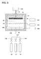
- Fig. 5 shows that transparent primer layer 62, thin transparent inorganic layer 611, thin transparent organic layer 612, and thin transparent inorganic layer 621 are applied in the stated order onto substrate sheet 61.
- Transparent primer layer composition is prepared by blending the above-mentioned transparent primer layer forming components or if desirable, dissolving them in solvents or dispersing them.
- a dispersion is required to form a liquid coating composition
- suitable homogenizers known in the art, such as a two-roller mill, a three-roller mill, a ball mill, a pebble mall, a COBOL mill, a tron mill, a sand mill, a sand grinder, a SQEVARI attritor, a high speed impeller homogenizer, a high speed stone mill, a high speed impact mill, DISPER, a high speed mixer, a homogenizer, an ultrasonic homogenizer, an open kneader, or a continuous kneader, and then employed.
- solvents to employ for dissolution when required: are water; ketones such as methyl ethyl ketone, methyl isobutyl ketone, or cyclohexanone; alcohols such as ethyl alcohol, n-propyl alcohol, or isopropyl alcohol; aliphatic hydrocarbons such as heptane or cyclohexane; aromatics such as toluene or xylene; glycols such as ethylene glycol or diethylene glycol; ether alcohols such as ethylene glycol monomethyl ether; ethers such as tetrahydrofuran, 1,3-dioxysolan or 1,4-dioxane; and halogen compounds such as dichloromethane or chloroform.
- ketones such as methyl ethyl ketone, methyl isobutyl ketone, or cyclohexanone
- alcohols such as ethyl alcohol, n-propyl alcohol, or isoprop
- the transparent primer layer forming composition prepared as above, onto a substrate sheet, employing, for example, a roller coating method, a gravure roller coating method, a direct gravure roller coating method, an air doctor coating method, a rod coating method, a kiss roller coating method, a squeezing roller coating method, a reverse roller coating method, a curtain flow coating method, a fountain method, a transfer coating method, a spray coating method, a dip coating method, or other appropriate methods. Subsequently, the resulting coating is heat-dried, followed by an aging treatment, whereby it is possible to apply a transparent primer layer onto a substrate sheet.
- a roller coating method for example, a roller coating method, a gravure roller coating method, a direct gravure roller coating method, an air doctor coating method, a rod coating method, a kiss roller coating method, a squeezing roller coating method, a reverse roller coating method, a curtain flow coating method, a fountain method, a transfer coating method, a spray coating method,
- the transparent primer layer forming composition when the transparent primer layer forming composition is applied onto a substrate sheet, it is preferable that after performing a suitable surface treatment selected from a flame treatment, an ozone treatment, a glow discharge treatment, a corona discharge treatment, a plasma treatment, a vacuum ultraviolet radiation exposure treatment, an electron beam exposure treatment, or a radiation exposure treatment, the transparent primer layer forming composition is applied onto a substrate sheet.
- a suitable surface treatment selected from a flame treatment, an ozone treatment, a glow discharge treatment, a corona discharge treatment, a plasma treatment, a vacuum ultraviolet radiation exposure treatment, an electron beam exposure treatment, or a radiation exposure treatment.
- the employed transparent primer layer forming components are the same as the thin transparent organic layer forming compositions, the same method as used to coat the thin transparent organic layer, to be described below, may be employed.
- forming methods of the thin transparent inorganic layer may, for example, be a vacuum deposition method, a sputtering method, an ion plating method, a reactive plasma deposition method, an method employing an electron cyclotron resonance plasma, a plasma chemical vapor deposition method, a thermochemical vapor deposition method, a photochemical vapor deposition method, a catalytic chemical vapor deposition method, and a vacuum ultraviolet radiation chemical vapor deposition method.
- the thin transparent inorganic layer is formed employing at least one of the catalytic chemical vapor deposition method (namely a Cat-CPD method), the reactive plasma deposition method (namely an RPD method), and the electron cyclotron resonance (ECR) plasma deposition method, which result in a layer exhibiting a relatively flat and smooth surface due to relatively little surface roughness on the formed thin transparent inorganic layer.
- the catalytic chemical vapor deposition method namely a Cat-CPD method
- RPD method reactive plasma deposition method
- ECR electron cyclotron resonance
- a specific method and deposition device of the above catalytic chemical vapor deposition method may suitably be selected from those described, for example, in JP-A Nos. 2002-69644 , 2002-69646 , 2002-299259 , 2004-211160 , 2004-217966 , 2004-292877 , 2004-315899 , and 2005-179693 , and may then be employed upon improvement of the shape suitable for the purpose of the present invention.
- a specific method and deposition device of the reactive plasma vapor deposition method may suitably be selected from those described, for example, in JP-A Nos. 2001-262323 , 2001-295031 , 2001-348660 , 2001-348662 , 2002-30426 , 2002-53950 , 2002-60929 , 2002-115049 , 2002-180240 , 2002-217131 , 2002-249871 , 2003-105526 , 2004-76025 , and 2005-34831 , and may then be employed upon improvement of the shape suitable for the purpose of the present invention.
- a specific method and deposition device of the ECR plasma deposition method may suitably be selected from those described, for example, on pages 152 - 154 and 226 in Tatsuo Asagi, "Hakumaku Sakusei no Kiso (Basis of Thin Layer Formation)” (published by Nikkan Kogyo Shinbun Sha, March 1996 ), and in JP-A Nos.
- employed as the deposition method of the thin transparent organic layer formed on the above-mentioned thin transparent inorganic layer may be a coating when the above primer layer is formed, or a deposition method.
- the transparent barrier sheet of the present invention it is preferable to employ the deposition method so that the thin transparent inorganic layer, functioning as a barrier layer, is not damaged.
- photopolymerization initiators when photopolymerization initiators are employed as a polymerization initiator after depositing a composition incorporating compounds having oxetane rings and compounds having oxirane rings as an essential component onto the thin transparent inorganic layer, via exposure to actinic radiation such as ultraviolet radiation, visible light, or near infrared radiation capable of allowing the polymerization initiators to initiate polymerization, it is possible to form a thin transparent organic layer upon polymerizing the compounds having oxetane rings and the compounds having oxirane rings.
- actinic radiation such as ultraviolet radiation, visible light, or near infrared radiation capable of allowing the polymerization initiators to initiate polymerization
- heat polymerization initiators when employed as a polymerization initiator, polymerization reaction is initiated from the heat polymerization initiators while heated, whereby it is possible to form the thin transparent organic layer via polymerizing compounds having oxetane rings and compounds having oxirane rings.
- deposition conditions may be set for each of the compounds. Further, when no polymerization reaction proceeds during layer formation via deposition and no problem occurs due to some difference in the deposition rate via monomers, deposition conditions may be set for the mixture of compositions.
- a specific method and layer forming device of the above-mentioned deposition method may suitably be selected from those described, for example, in JP-A Nos. 5-125520 , 6-316757 , 7-26023 , 9-272703 , 9-31115 , 10-92800 , 10-168559 , 10-289902 , 11-172418 , 2000-87224 , 2000-127186 , 2000-348971 , 2003-3250 , 2003276115 , 2003-300273 , 2003-322859 , 2003-335880 , 2003-341003 , 2005-14483 , 2005-125731 , and 2005-178010 , as well as in Japanese Patent Publication Open to Public Inspection (under PCT Application) Nos. 8-503099 , 2001-508089 , 2001-518561 , and 2004-524958 , and may then be employed upon improvement of the shape suitable for the purpose of the present invention.
- T in K of the substrate sheet
- Tg in K
- Maximum attained temperature T (in K) of the substrate sheet during formation of the thin transparent organic layer and the thin transparent inorganic layer and casting time S (in seconds), as described herein, relate to the process forming single layer.
- T and S represent casting conditions of each of the single layers.
- casting time represents the casting time at a certain point of the substrate sheet. 1.21 ⁇ T ⁇ s / 1000 ⁇ 460 1.21 ⁇ T ⁇ s / 1000 ⁇ 350
- the transparent barrier sheet of the present invention other than the above-mentioned essential layers, functional layers such as an antistatic layer, an adhesion layer, an antireflection layer, an ultraviolet radiation protective layer or a near infrared radiation protective layer, which are provided to meet requirements, may be coated via suitable selection of the coating method employed for the above-mentioned transparent primer layer, thin transparent inorganic layer or thin transparent organic layer.
- functional layers such as an antistatic layer, an adhesion layer, an antireflection layer, an ultraviolet radiation protective layer or a near infrared radiation protective layer, which are provided to meet requirements, may be coated via suitable selection of the coating method employed for the above-mentioned transparent primer layer, thin transparent inorganic layer or thin transparent organic layer.
- a biaxially stretched polyethylene terephthalate (COSMOSHINE A-4300, produced by TOYOBO Co., Ltd.) was prepared. A 10 °C cooling plate was placed on the reverse side of the substrate.
- a thin transparent organic layer forming composition was prepared by completely dissolving 40 parts of 3,4-epoxycyclohexenylmethyl-3',4'-epoxycyclohexane carboxylate, 59 parts of di[1-ethyl(3-oxetanyl)]methyl ether, and 1 part of hexafluoroantimonate allyliodonium. After lowering the pressure in the tank to an order of 10 -4 Pa, the resulting composition was introduced into an organic deposition source.
- Table 1 shows the layer thickness and the layer forming time during layer formation of the resulting thin transparent inorganic and organic layers, and the maximum attained temperature T (in K) of the substrate sheet.
- Maximum attained temperature T (in K) during layer formation was determined as follows. A thermo-label was adhered onto the surface of the formed layer and after forming the thin layer, the temperature was confirmed.
- COSMOSHINE A-4300 produced by TOYOBO Co., Ltd.
- Transparent Barrier Sheets R-1A and R-1B were prepared and employed as a comparative example.
- Table 1 shows the thickness of the resulting thin Transparent inorganic and organic layers, the layer forming time during layer formation, and the maximum attained temperature T (in K) of the substrate sheet during layer formation.
- Maximum attained temperature T (in K) during layer formation was determined as follows. A thermo-label was adhered onto the surface of the formed layer and after forming the thin layer, the temperature was confirmed.
- the transparent barrier sheets, prepared as above, were evaluated for gas barrier properties and bending resistance, as described below. Table 1 shows the results.
- the above sheet was evaluated in the same manner as for water vapor barrier properties. Table 1 Inv. Inv. Inv. Inv. Inv. Inv. Inv. Comp. Comp. Transparent Barrier Sheet No.
- Transparent Barrier Sheets 1-A - 1-F exhibited superior gas barrier properties and bending resistance to Comparative Barrier Sheets R-1A and R-1B.
- each of Transparent Barrier Sheets 2-A - 2-F was produced by forming a thin transparent inorganic layer and a thin transparent organic layer, employing the methods described in following 1) and 2).
- Table 2 shows the thickness of the resulting thin transparent inorganic layer and thin transparent organic layer, the deposition time during deposition, and maximum attained temperature T (in K) of the substrate sheet during deposition.
- the resulting transparent barrier sheet was evaluated for gas barrier properties and bending resistance, employing the same methods as in Example 1. Table 2 shows the results.
- Transparent Barrier Sheets R-2A and R-2B were prepared employing the same method as for Transparent Barrier Sheets R-1A and R-1B prepared in Example 1.
- Table 2 shows the thickness of the resulting thin transparent inorganic layer and thin transparent organic layer, the deposition time during deposition, and maximum attained temperature T (in K) of the substrate sheet during deposition. Maximum attained temperature during layer formation was determined as follows. A thermo-label was adhered onto the surface of the formed layer and after forming the thin layer, temperature T (in K) was confirmed.
- the resulting transparent barrier sheet was evaluated for gas barrier properties and bending resistance, employing the same methods as in Example 1. Table 2 shows the results.
- each of the compounds described in Table 2 is the following compound, and the ratio refers to the ratio by weight.
- Barrier Sheets 2-A - 2-F of the present invention exhibited the desired gas barrier properties as well as desired bending resistance contrary to Comparative Barrier Sheets R-2A and R-2B.
- a 75 ⁇ m thick biaxially stretched polyethylene terephthalate film (LUMILAR-T60, produced by Toray Industries, Inc.), as a substrate sheet, was subjected to corona discharge treatment.
- a coating composition prepared by blending 98 parts of di[1-ethyl(3-oxetanyl)]methyl ether and 2 parts of diphenyl-4-thiophenoxysulfonium hexafluoroantimonate, as a polymerization initiator, was applied to reach a coating thickness of 0.5 ⁇ m.
- ultraviolet radiation in an amount which allowed the composition to sufficiently undergo reaction in the atmosphere to result in curing, was emitted employing an ultraviolet radiation exposure device (being a UV curing device incorporating a conveyer, produced by Iwasaki Electric Co., Ltd.), whereby a transparent primer layer was formed.
- an ultraviolet radiation exposure device being a UV curing device incorporating a conveyer, produced by Iwasaki Electric Co., Ltd.
- Table 3 shows the thickness of the resulting thin transparent inorganic layer and thin transparent organic layer, the deposition time during deposition, and maximum attained temperature T (in K) of the substrate sheet during deposition. Maximum attained temperature during layer formation was determined as follows. A thermo-label was adhered onto the surface of the formed layer and after forming the thin layer, temperature T (in K) was confirmed.
- the resulting transparent barrier sheet was evaluated for gas barrier properties and bending resistance, employing the same methods as in Example 1. Table 3 shows the results.
- IRUGACURE 907 produced by Ciba Specialty Chemicals Co.
- Table 3 shows the thickness of the resulting thin transparent inorganic layer and thin transparent organic layer, the layer forming time during layer formation, and maximum attained temperature T (in K) of the substrate sheet during layer formation. Maximum attained temperature during layer formation was determined as follows. A thermo-label was adhered onto the surface of the formed layer and after forming the thin layer, temperature T (in K) was confirmed.
- Barrier Sheets 3-A - 3-F of the present invention exhibited the desired gas barrier properties as well as desired bending resistance contrary to Comparative Barrier Sheet R-3.
Landscapes
- Chemical & Material Sciences (AREA)
- Health & Medical Sciences (AREA)
- Chemical Kinetics & Catalysis (AREA)
- Medicinal Chemistry (AREA)
- Polymers & Plastics (AREA)
- Organic Chemistry (AREA)
- Laminated Bodies (AREA)
- Wrappers (AREA)
- Coating Of Shaped Articles Made Of Macromolecular Substances (AREA)
Abstract
Disclosed is a transparent barrier sheet characterized by comprising at least one transparent inorganic thin film layer and at least one transparent organic thin film layer on a base sheet on which a transparent primer layer is arranged. This transparent barrier sheet is also characterized in that the transparent organic thin film layer is formed by polymerizing a composition containing a compound having an oxetane ring and a compound having an oxirane ring. This transparent barrier sheet is excellent in gas barrier property and bending resistance. Also disclosed is a method for producing such a transparent barrier sheet.
Description
- The present invention relates to a transparent barrier sheet for packaging employed in the packaging fields of foods and medicines, or a transparent barrier sheet employed for members related to electronic equipment, a transparent barrier sheet at extremely low permeability of gases such as oxygen or water vapor, and a production method of the same.
- In recent years, in order to confirm contents, transparent packaging materials have been sought for packaging foods and medicines. Further, in order to minimize effects of permeated oxygen, water vapor, and other gases which adversely affect the content, gas barrier properties are demanded to maintain function and properties of packaged goods. Conventionally, when a high degree of gas barrier properties is demanded, packaging materials have been employed in which foil composed of metals such as aluminum is employed as a gas barring layer. However, the above packaging materials, which employ metal foil as a gas barrier, exhibit a high degree of gas barrier properties, which are not affected by temperature and humidly but have resulted in problems in which it is not possible to confirm contents through the packing material and it is not possible to use a metal detector during inspection.
- Consequently, in recent years, in order to enhance the performance, have been developed and proposed, for example, are transparent barrier materials which are prepared in such a manner that a sputtered layer of metal oxides such as silicon oxide or aluminum oxide are provided on one side of a plastic substrate. However, in order to enhance the gas barrier properties, when the thickness of such inorganic material layer is increased beyond a certain value, cracking is induced due to insufficient flexibility and plasticity, whereby the gas barrier properties are degraded.
- Further, in order to overcome the above drawbacks, it is proposed to realize excellent gas barrier properties by applying a thin organic layer of a cross-linked structure together with a thin inorganic layer onto a transparent plastic substrate (refer, for example, to Patent Documents 1 and 2).
- In such a transparent barrier sheet, commonly, after coating polymerizable monomers or providing the same on a substrate via deposition, a thin organic layer is formed via cross-linking the monomers, employing light or heat. However, the thin organic layer prepared by cross-linking monomers having radically polymerizable unsaturated double bonds, represented by (meth)acryl based monomers, which is provided employing these methods, commonly exhibits large contraction ratio after polymerization compared to one prior to polymerization, whereby the resulting transparent barrier sheet occasionally results in curling, and gas barrier properties is occasionally degraded due to cracking, caused by poor bending resistance since the resulting thin organic layer is brittle.
- Consequently, in order to overcome the above concerns, thin organic layers utilizing cationically polymerizable monomers are proposed (refer, for example, to Patent Documents 3 - 5). The bending resistance of the resulting thin organic layer itself is improved compared to those prepared by radical polymerization, but is still not at a satisfactory level. However, at present, including a close contact between the substrate sheet and the thin layer, at present, a practical satisfaction has not yet been attained. Further, when the thin organic layer is formed via coating, the thin inorganic layer occasionally results in defects, whereby problems occasionally occur in which the resulting gas barrier properties is degraded.
(Patent Document 1) Japanese Patent Publication Open to Public Inspection (hereinafter referred to as JP-A) No.2003-276115
(Patent Document 2)JP-A No. 2003-300273
(Patent Document 3)JP-A No. 2003-251731
(Patent Document 4)JP-A No. 2004-524958
(Patent Document 5)JP-A No. 2005-125731 - The present invention was achieved to overcome the above conventional technical problems. An object of the present invention is to provide a transparent barrier sheet which exhibits excellent gas barrier properties and excellent bending resistance, and a production method thereof.
- The above object of the present invention is accomplished employing the following embodiments.
- (1) A transparent barrier sheet comprising:
- a substrate sheet having thereon a transparent primer layer;
- a transparent inorganic thin layer; and
- a transparent organic thin layer,
- wherein the transparent organic thin layer is formed by polymerizing a composition comprising:
- a compound having an oxetane ring; and
- a compound having an oxirane ring.
- (2) A transparent barrier sheet of the above-described in item 1,
wherein the compound having an oxetane ring comprises at least two oxetane rings in the molecule. - (3) A transparent barrier sheet of the above-described in items 1 or 2,
wherein the compound having an oxirane ring comprises at least two oxirane rings in the molecule. - (4) A transparent barrier sheet of the above-described in any one of items 1 to 3,
wherein the composition to form the transparent organic thin layer further comprises a compound having a group selected from the group consisting of an alkenyl ether group, an allene ether group, a ketene acetal group, a tetrahydrofuran group, an oxepane group, a single ring acetal group, a double ring acetal group, a lactone group; a cyclic orthoester group and a cyclic carbonate group. - (5) A transparent barrier sheet of the above-described in any one of items 1 to 4,
wherein the transparent inorganic thin layer and the transparent organic thin layer are provided in that order on the transparent primer layer of the substrate sheet. - (6) A transparent barrier sheet of the above-described in item 5,
wherein a second transparent inorganic thin layer is further provided on the transparent organic thin layer. - (7) A transparent barrier sheet of the above-described in any one of items 1 to 4,
wherein a second transparent inorganic thin layer; and a second transparent organic thin layer are provided in that order on the substrate sheet having thereon the transparent primer layer, whereby at lease two units each composed of a transparent inorganic thin layer and a transparent organic thin layer are formed on the substrate sheet. - (8) A transparent barrier sheet of the above-described in any one of items 1 to 7,
wherein a thickness of the transparent organic thin layer is from 50 nm to 5.0 µm. - (9) A method of producing a transparent barrier sheet comprising the steps of:
- forming a transparent inorganic thin layer on a substrate sheet having thereon a primer layer employing a catalytic chemical vapor deposition method, a reactive plasma deposition method or an electron cyclotron resonance plasma deposition method; and
- forming a transparent organic thin layer.
- (10) A method of producing a transparent barrier sheet of the above-described in item 9,
wherein the transparent organic thin layer is formed by the steps of:- depositing on the transparent inorganic thin layer vapors of:
- a compound having an oxetane ring;
- a compound having an oxirane ring; and
- a polymerization initiator,
- polymerizing the deposited vapors by irradiating with actinic rays or by heating.
- depositing on the transparent inorganic thin layer vapors of:
- (11) A method of producing a transparent barrier sheet of the above-described in items 9 or 10,
wherein a maximum attained temperature T (in K) of the substrate sheet is controlled to be in the range of 243 to 383 K during the formations of the transparent inorganic thin layer and the transparent organic thin layer. - (12) A method of producing a transparent barrier sheet of the above-described in
item 11, - Based on the present invention, it was possible to provide a transparent barrier sheet which exhibited excellent gas barrier properties and excellent bending resistance and the production method thereof.
-
-
Fig. 1 is a schematic sectional view of a transparent barrier sheet incorporating one unit of a transparent thin inorganic layer/transparent thin organic layer on a substrate sheet provided with a transparent primer layer. -
Fig. 2 is a schematic sectional view of a transparent barrier sheet incorporating two units of a transparent thin inorganic layer/transparent thin organic layer on a substrate sheet provided with a transparent primer layer. -
Fig. 3 is a schematic sectional view of a transparent barrier sheet incorporating 5 units of a transparent thin inorganic layer/transparent thin organic layer on a substrate sheet provided with a transparent primer layer. -
Fig. 4 is a schematic sectional view of a transparent barrier sheet incorporating two units of a transparent thin inorganic layer/transparent thin organic layer on both sides of a substrate sheet coated with a transparent primer layer on both aforesaid sides. -
Fig. 5 is a schematic sectional view of a transparent barrier sheet incorporating a transparent thin inorganic layer/transparent thin organic layer/transparent thin inorganic layer on a substrate sheet provided with a transparent primer layer. -
Fig. 6 is a view showing a casting apparatus employing a catalytic chemical vapor deposition method. -
- 11, 21, 31, 41, 61: substrate sheet
- 12, 22, 32, 42, 42', 62: transparent primer layer
- 111, 211, 221, 311, 321, 331, 341, 351, 411, 411', 421, 421',
- 611, 621: transparent thin
inorganic layer - 612: transparent thin organic layer
- 50: vacuum vessel
- 51: substrate sheet provided with a transparent primer layer
- 52: holding mechanism
- 53: cooling mechanism
- 54: heater (tungsten)
- 55: gas inlet
- 56: hydrogen gas source
- 57: ammonia gas source
- 58: silane gas source
- 59: shielding member
- 501: driving device for shielding member
- 502: heating electric source for heater
- 503: vacuum pump
- 504: cooling source
- 505: device for inlet
- 506: space
- V56, V57, V58: on-off valve
- The transparent barrier sheet of the present invention and the production method thereof will now be detailed.
- The transparent barrier sheet of the present invention incorporates a substrate sheet coated with a transparent primer layer having thereon at least one thin transparent inorganic layer, and at least one thin transparent organic layer. Each of the constituting materials of the transparent sheet of the present invention will now be described. The visible light transmittance of the transparent barrier sheet of the present invention is 50 - 95%.
- Substrate sheets employed in the present invention may be used without any particular limitation as long as they result in neither dimensional deformation when the following production method is employed, nor curling after coating of a thin layer. Listed as resins to form the sheet may, for example, be polyester based resins such as polyethylene terephthalate (PET), or polyethylene naphthalate; polyolefin based resins such as polyethylene or polypropylene; styrene based resins such as polystyrene or acrylonitrile-styrene copolymers; acryl based resins such as polymethyl methacrylate or methacrylic acid-maleic acid copolymers; cellulose based resins such as triacetyl cellulose; vinyl based resins such as polyvinyl chloride; imido based resins such as polyimide, fluorinate polyimide, or polyetherimide; amido based resins such as nylon 6, nylon 66, or MXD nylon 6; polycarbonate resins composed of bisphenol A, bisphenol Z, or 1,1-bis(4-hydroxyphenyl)-3,3,5-trimethylcyclohexane; polyacrylate resins, fluororesins; polyethersulfone resins; polysulfone resins; polyether ketone resins; or alicyclic polyolefin resins such as alicyclic polyolefin, or alicyclic olefin copolymers.
- Substrate sheets include those which have been stretched or not stretched as long as the object of the present invention is not adversely affected, and preferred are those which exhibit sufficient mechanical strength and dimensional stability. Of these, biaxially stretched polyethylene terephthalate or polyethylene naphthalate is preferred for the use of thin substrate sheets. On the other hand, when substrate sheets are relatively thick, the above-cited polyester based resins such as polyethylene terephthalate or polyethylene naphthalate, polyarylate resins, polyether sulfone resins, polycarbonate resins, or alicyclic polyolefin resins are preferred in view of dimensional stability, chemical resistance, and heat resistance.
- Further, if desired, various additives may be added to substrate sheets of the present invention in a range which does not adversely affect the present invention. Cited as such additives may, for example, be plasticizers, dyes and pigments, antistatic agents, UV absorbers, antioxidants, minute inorganic particles, peeling enhancing agents, leveling agents, inorganic layer-shaped silicates, and lubricants.
- The thickness of the substrates may be appropriately varied depending on the use of the transparent barrier sheet of the present invention. Further, when considering suitability of a packaging material, other than a single resin sheet, it is possible to select and employ appropriate sheets laminated with a different quality sheet. However, when considering machinability during formation of the transparent thin inorganic layer and the thin transparent organic layer described below, in practice, the thickness is preferably in the range of 6 - 400 µm, but is most preferably in the range of 25 - 100 µm. When employed for electronic devices such as liquid crystal display elements, dye type solar batteries, organic or inorganic ELs, electronic paper, or fuel cells, appropriate thickness is chosen based on various uses. Of these, when employed as a substitute of a glass substrate, the substrate is prepared according to glass substrate specifications, and after production, the thickness is preferably in the range of relatively thick 50 - 800 µm, but is most preferably in the range of 50 - 400 µm in order to match with the process for the glass substrate.
- Further, when mass productivity of the transparent barrier sheets of the present invention is considered, it is preferable to prepare them in the form of a continuous long-length film so that it is feasible to continuously form the thin transparent inorganic layer and the thin transparent organic layer onto the substrate sheet.
- Subsequently, a transparent primer layer, coated onto the substrate sheet, will now be described.
- The transparent primer layer applied onto the substrate sheet is provided to enhance adhesion to the thin layer applied thereon and to secure the flatness of the surface of the applied thin layer. By providing the above transparent primer layer, it is possible to minimize defects of the thin transparent inorganic layer due to projections and foreign matter on the substrate sheet, to enhance adhesion between the substrate sheet and the thin transparent inorganic layer, and further, it is possible to prepare a transparent barrier sheet which exhibits excellent bending resistance.
- It is also possible to prepare the transparent primer layer via coating of a resin liquid coating composition prepared by dissolving resins in various solvents and subsequently drying the coating. Further, after drying, if desired, a cross-linking reaction may be performed. Further, it is also possible to preferably employ a layer which is prepared as follows. Any of metal alkoxides, UV radiation curing resins, electron beam curing resins, or heat curing resins is coated in the absence of solvents, or a coating composition prepared by diluting any of the above with solvents is coated, subsequently dried, and cured.
- Resins, which are employed to prepare a liquid resin coating composition for the above-mentioned transparent primer layer, upon being dissolved in various solvents, include polyester based resins, urethane based resins, acryl based resins, styrene based resins, cellulose based resins, polyvinyl acetal based resins, and vinyl chloride based resins. It is possible to select and employ any appropriate one(s) from these.
- Further listed as metal alkoxides are those metals with alcohol such as methyl alcohol, ethyl alcohol, or isopropyl alcohol, and listed as metals may be silicon, titanium, or zirconium.
- As UV radiation curable resins or electron beam curable resins, other than compounds such as styrene based monomers or compounds having an unsaturated double bond in the molecule such as acryl based monomers, selected and employed may be any suitable one(s) from compounds having an oxetane ring, which are employed to form the thin transparent organic layer described below, and compounds having an oxirane ring, or compounds having an alkenyl ether group, an allene ether group, a ketene acetal group, a tetrahydrofuran group, an oxepane group, a single ring acetal group, a double ring acetal group, a lactone group, a cyclic orthoester group, or a cyclic carbonate group. A composition prepared by combining the above compounds with cross-linking agents is applied onto substrate sheet to form a layer followed by curing, whereby it is possible to form a transparent primer layer.
- Further, heat curable resins are suitably selected from combinations with compounds or resins having an oxirane ring and an amino group, combinations of acid anhydrides with compounds or resins having an amino group, or combinations of compounds or resins having hydroxyl group with compounds or resins having an isocyanate group, other than heat curing resins such as phenol resins, epoxy resins, melamine resins, urea resins, unsaturated polyester, or alkyd resins, which are widely employed, and then employed.
- The above transparent primer layer may be composed of a single layer or a plurality of layers. The thickness is commonly in the range of 0.05 - 5.0 µm, but is preferably in the range of 0.1 - 2.0 µm.
- The thin transparent inorganic layer and the thin transparent organic layer applied onto the transparent primer layer of the substrate sheet coated with the transparent primer layer will now be detailed.
- The thin transparent inorganic layers according to the present invention may be employed without particular limitation as long as they exhibit gas barrier properties and are transparent. Specific examples which form the thin inorganic layer include oxides incorporating at least one of Si, Al, In, Sn, Zn, Mg, Ca, K, Sn, Na, B, Ti, Pb, Zr, Y, In, Ce, and Ta, or nitrides and oxidized nitrides. Suitable ones may be selected and then employed. Further, when employed to confirm contents or applied to electronic devices, those, which have not clear maximum absorption wavelength in the visible region, are preferred.
- Of these, employed as inorganic oxides may be oxides of metals such as silicon (Si), aluminum (Al), Zinc (Zn), magnesium (Mg), calcium (Ca), potassium (K), tin (Sn), sodium (Na), boron (B), titanium (Ti), lead (Pb), zirconium (Zr), Yttrium (Y), or Indium (In).
- Of these, metal oxides are represented by MOx (in which M represents a metal element, and each value of X differs in the range depending on the metal element), such as SiOx, AlOx, or MgOx. Further, with regard to the range of the X value, the possible value range is as follows; 0 < X ≤ 2 for silicon (Si), 0 < X ≤ 1 for aluminum (Al), 0 < X ≤ 1 for zinc (Zn), 0 < X ≤ 1 for magnesium (Mg), 0 < X ≤ 1 for calcium (Ca), 0 < X ≤ 0.5 for potassium (K), 0 < X ≤ 2 for tin (Sn), 0 < X ≤ 0.5 for sodium (Na), 0 < X ≤ 1.5 for boron (B), 0 < X ≤ 2 for titanium (Ti), 0 < X ≤ 1 for lead (Pb), 0 < X ≤ 2 for zirconium (Zr), 0 < X ≤ 1.5 for yttrium (Y), and 0 < X ≤ 1 for indium (In). In the present invention, in terms of gas barrier properties, oxides of silicon (Si) and aluminum (Al) are preferred. In such a case, it is preferable to employ silicon oxide (SiOx) in the range of 1.0 ≤ X ≤ 2.0 and aluminum oxide (AlOx) in the range of 0.5 ≤ X ≤ 1.5.
- In view of transparency as an inorganic nitride, silicon nitrides are preferred. Further, as such mixtures, silicon nitride oxides are preferred. Silicon nitride oxide is represented by SiOxNy. When enhancement of close contact capability is manly intended, it is preferable that an oxygen-rich layer is formed resulting in 1 < x < 2 and 0 < y < 1. When enhancement of water vapor barrier properties is mainly intended, it is preferable that a nitrogen-rich layer is formed resulting in 0 < x < 0.8 and 0.8 < y < 1.3.
- The thickness of thin transparent inorganic layers is commonly 10 - 1,000 nm, but is preferably 20 - 1,000 nm to assure desired barrier properties.
- The thin transparent organic layer will now be detailed.
- The thin transparent organic layer according to the present invention is featured to be a thin layer which is formed via polymerization of compositions incorporating oxetane ring containing compounds and oxirane ring containing compounds.
- Examples of the above compounds having a oxetane ring include those described in
JP-A Nos. 5-170763 5-371224 6-16804 7-17958 7-173279 8-245783 8-301859 10-237056 10-330485 11-106380 11-130766 11-228558 11-246510 11-246540 11-246541 11-322735 2000-1482 2000-26546 2000-191652 2000-302774 2000-336133 2001-31664 2001-31665 2001-31666 2001-40085 2003-81958 2003-89693 2001-163882 2001-226365 2001-278874 2001-278875 2001-302651 2001-342194 2002-20376 2002-80581 2002-193965 2002-241489 2002-275171 2002-275172 2002-322268 2003-2881 2003-12662 2003-81958 2004-91347 2004-149486 2004-262817 2005-125731 2005-171122 2005-238446 2005-239573 2005-336349 11-500422 - Further employed as compounds having an oxirane ring may be various types of compounds. Specific examples include resins, the terminals of which are modified with a glycidyl group, such as aliphatic polyglycidyl ether, polyalkylene glycol diglycidyl ether, tertiary carboxylic acid monoglycidyl ether, polycondensation products of bisphenol A with epichlorohydrine, polycondensation products of hydrogenated bisphenol A with epichlorohydrine, polycondensation products of brominated bisphenol A with epichlorohydrine, and polycondensation products of bisphenol F with epichlorohydrine, as well as glycidyl modified phenol novolak resins, glycidyl modified o-cresol novolak resins, 3,4-epoxycyclohexenylmethyl-3',4'-epoxycyclohexane carboxylate, 3,4-epoxy-4-methylcyclohexenylmethyl-3',4'-epoxy-4'-methylcyclohexane carboxylate, 1,2-bis(3,4-epoxy-4-methylcyclohexycenylcarbonyloxy)ethane, and dipentane dioxide. Further, it is also possible to suitably employ the compounds described on pages 778 - 787 of "11290 no Kagaku Shohin (11290 Chemical Products)", Kagaku Kogyo Nippo-Sha, and the compounds described in
JP-A No. 2003-341003 - With regard to the above compounds having oxetane ring(s) or oxirane ring(s), in order to retard variation of bending resistance due to ambient temperature around the thin transparent organic layer formed via polymerization, it is preferable that at least either of the above-mentioned compounds is one having at least two oxetane rings in the molecule or one having at least two oxirane rings in the molecule.
- Further, in the present invention, to polymerize compounds having oxetane rings and compounds having oxirane rings via exposure to actinic radiation or heating, other than those, polymerization initiators are incorporated in the composition as an essential component.
- Listed as polymerization initiators to polymerize the compounds according to the present invention may be photopolymerization initiators or heat polymerization initiators which allow the oxetane ring and the oxirane ring to undergo cationic polymerization. Of these, photopolymerization initiators may be employed without particular limitation as long as they can generate Brφnsted acid or Lewis acid. For example, cationic photopolymerization initiators employed in chemical amplification type photoresists and light carving resins (refer to pages 187 - 192 of "imagine yo Yuuki Zairyo (Organic Materials for Imaging"), edited by Yuuki Electronics Zairyo Kenkyuu Kai, Bunshin Shuppan, (1993)), may, if suitable, be selected and then employed.
- Specific examples of such cationic photopolymerization initiators include s-triazine compounds substituted with a trihalomethyl group, such as 2,4,6-tris(trichloromethyl)-1,3,5-triazine, 2-(4-methoxyphenyl)-4,6-bis(trichloromethyl)-1,3,5-triazine, and the compounds described in
JP-A No. 2-306247 JP-A No. 62-57646 JP-A Nos. 5-107999 5-181271 8-16080 8-305262 2000-47552 2003-66816 U.S. Patent No. 5,759,721 , and European Patent No.1,029,258 may, if suitable, be selected and then employed. - Further, without particular limitation, employed as the cationic heat polymerization initiators may be onium salts such as sulfonium salts, ammonium salts, or phosphonium salts and silanol-aluminum complexes. Of these, listed as cationic heat polymerization initiators, when other essential components result in no problem while heated at equal to or higher than 150 °C, are the benzylsulfonium salts described in
JP-A Nos. 58-37003 63-223002 JP-A No. 56-152833 JP-A Nos. 63-8365 63-8366 1-83060 1-290658, 2-1470 2-196812 2-232253 3-17101 3-47164 3-48654 3-145459 3-200761 3-237107 4-1177 4-210673 8-188569 8-188570 11-29609 11-255739 2001-55374 - The amount of above polymerization initiators, when the amount of compounds having oxetane rings and compounds having oxirane rings is to be 100 parts by weight, is commonly in the range of 0.01 - 30 parts by weight, but is preferably in the range of 0.05 - 20 parts by weight.
- Further, the thickness of the thin transparent organic layer is commonly 50 nm - 5.0 µm, but is preferably 50 nm - 2.0 µm in terms of achieving flatness and bending resistance.
- Further, in the present invention, other than the above compounds having oxetane rings and compounds having oxirane rings, to regulate viscosity of compositions and to control the polymerization reaction, added may be compounds having an alkenyl ether group, an allene ether group, a ketene acetal group, a tetrahydrofuran group, an oxepane group, a single ring acetal group, a double ring acetal group, a lactone group, a cyclic orthoester group, or a cyclic carbonate group. Those having any of the above functional group(s) may be employed without particular limitation. Of these, compounds having an alkenyl ether group include hydroxyethyl vinyl ether, hydroxylbutyl vinyl ether, dodecyl vinyl ether, propenylether propylene carbonate, and cyclohexyl vinyl ether. Cited as compounds having at least two vinyl ether groups may be cyclohexane dimethanol divinyl ether, triethylene glycol divinyl ether, and novolak type divinyl ether.
- In the present invention, it is preferable that a thin transparent inorganic layer and a thin transparent organic layer are applied in the stated order onto the substrate sheet coated with the transparent primer layer, since defects such as cracking are minimized when external stress is applied to the thin transparent inorganic layer coated to secure gas barrier properties. Consequently, in order to secure gas barrier properties, it is preferable that a thin transparent inorganic layer is further applied onto the thin transparent organic layer.
- In order to enhance gas barrier properties and bending resistance at high temperature and high humidity, when a thin transparent inorganic layer and a thin transparent organic layer are regarded as one unit, it is preferable that at least two such units are applied onto the transparent primer layer on the substrate sheet coated with the transparent primer layer. Numbers of coated units are commonly 2 - 10 units, but are preferably 2 - 5 units.
- In the above case in which a plurality of units is applied, when it is necessary to consider abrasion resistance, it is preferable that the thickness of the thin transparent organic layer, which is to be the uppermost layer, is more than that of the lower thin transparent organic layer. In such a case, it is preferable to satisfy the following relationship;

wherein R1 represent the maximum layer thickness of the lower transparent organic layer, while R2 represents the thickness of the uppermost thin transparent organic layer. Further, the thickness of the thin transparent inorganic layer and the thin transparent organic layer, other than the uppermost thin transparent organic layer, are as follows. The thickness of the thin transparent inorganic layer is commonly 10 - 1,000 nm, but is preferably 20 - 500 nm. The thickness of the thin transparent organic layer is commonly 50 nm - 2.0 µm, but is preferably 50 nm - 1.0 µm. - Further, in the transparent barrier sheet of the present invention, other than the above-mentioned essential layers, if desirable, coated may be functional layers such as an antistatic layer, an adhesion layer, an electrically conductive layer, an antireflection layer, an ultraviolet radiation protective layer. Coated location may be suitably selected in response to the use.
-
Figs. 1 - 5 are schematic sectional views of the transparent barrier sheets of the present invention. However, if embodiments are in the range of the present invention, the present invention is not limited to these embodiments. -
Fig. 1 shows that coated ontosubstrate sheet 11 aretransparent primer layer 12, thin transparentinorganic layer 111, and thin transparentorganic layer 112 in the stated order.Fig. 2 shows that when thin transparentinorganic layer 211 and thin transparentorganic layer 212 are regarded as one unit, two units are applied ontotransparent primer layer 22 ofsubstrate sheet 21 coated withtransparent primer layer 22.Fig. 3 shows that 5 units are coated compared to two units inFig. 2 .Fig. 4 shows that both sides of a substrate sheet are coated with transparent primer layers 42 and 42'.Fig. 5 shows thattransparent primer layer 62, thin transparentinorganic layer 611, thin transparentorganic layer 612, and thin transparentinorganic layer 621 are applied in the stated order ontosubstrate sheet 61. - Transparent primer layer composition is prepared by blending the above-mentioned transparent primer layer forming components or if desirable, dissolving them in solvents or dispersing them.
- When a dispersion is required to form a liquid coating composition, it is possible to select any of the suitable homogenizers known in the art, such as a two-roller mill, a three-roller mill, a ball mill, a pebble mall, a COBOL mill, a tron mill, a sand mill, a sand grinder, a SQEVARI attritor, a high speed impeller homogenizer, a high speed stone mill, a high speed impact mill, DISPER, a high speed mixer, a homogenizer, an ultrasonic homogenizer, an open kneader, or a continuous kneader, and then employed.
- Further listed as solvents to employ for dissolution, when required: are water; ketones such as methyl ethyl ketone, methyl isobutyl ketone, or cyclohexanone; alcohols such as ethyl alcohol, n-propyl alcohol, or isopropyl alcohol; aliphatic hydrocarbons such as heptane or cyclohexane; aromatics such as toluene or xylene; glycols such as ethylene glycol or diethylene glycol; ether alcohols such as ethylene glycol monomethyl ether; ethers such as tetrahydrofuran, 1,3-dioxysolan or 1,4-dioxane; and halogen compounds such as dichloromethane or chloroform.
- It is possible to apply the transparent primer layer forming composition, prepared as above, onto a substrate sheet, employing, for example, a roller coating method, a gravure roller coating method, a direct gravure roller coating method, an air doctor coating method, a rod coating method, a kiss roller coating method, a squeezing roller coating method, a reverse roller coating method, a curtain flow coating method, a fountain method, a transfer coating method, a spray coating method, a dip coating method, or other appropriate methods. Subsequently, the resulting coating is heat-dried, followed by an aging treatment, whereby it is possible to apply a transparent primer layer onto a substrate sheet.
- Further, in the present invention, when the transparent primer layer forming composition is applied onto a substrate sheet, it is preferable that after performing a suitable surface treatment selected from a flame treatment, an ozone treatment, a glow discharge treatment, a corona discharge treatment, a plasma treatment, a vacuum ultraviolet radiation exposure treatment, an electron beam exposure treatment, or a radiation exposure treatment, the transparent primer layer forming composition is applied onto a substrate sheet. By treating the surface of the substrate sheet as described above, it is possible to enhance adhesion between the substrate sheet and the transparent primer layer.
- When the employed transparent primer layer forming components are the same as the thin transparent organic layer forming compositions, the same method as used to coat the thin transparent organic layer, to be described below, may be employed.
- The forming method of the thin transparent inorganic layer formed on the transparent primer layer will now be detailed.
- Listed as forming methods of the thin transparent inorganic layer may, for example, be a vacuum deposition method, a sputtering method, an ion plating method, a reactive plasma deposition method, an method employing an electron cyclotron resonance plasma, a plasma chemical vapor deposition method, a thermochemical vapor deposition method, a photochemical vapor deposition method, a catalytic chemical vapor deposition method, and a vacuum ultraviolet radiation chemical vapor deposition method. Of these methods, it is preferable that the thin transparent inorganic layer is formed employing at least one of the catalytic chemical vapor deposition method (namely a Cat-CPD method), the reactive plasma deposition method (namely an RPD method), and the electron cyclotron resonance (ECR) plasma deposition method, which result in a layer exhibiting a relatively flat and smooth surface due to relatively little surface roughness on the formed thin transparent inorganic layer.
- A specific method and deposition device of the above catalytic chemical vapor deposition method may suitably be selected from those described, for example, in
JP-A Nos. 2002-69644 2002-69646 2002-299259 2004-211160 2004-217966 2004-292877 2004-315899 2005-179693 - Further, a specific method and deposition device of the reactive plasma vapor deposition method may suitably be selected from those described, for example, in
JP-A Nos. 2001-262323 2001-295031 2001-348660 2001-348662 2002-30426 2002-53950 2002-60929 2002-115049 2002-180240 2002-217131 2002-249871 2003-105526 2004-76025 2005-34831 - Still further, a specific method and deposition device of the ECR plasma deposition method may suitably be selected from those described, for example, on pages 152 - 154 and 226 in Tatsuo Asagi, "Hakumaku Sakusei no Kiso (Basis of Thin Layer Formation)" (published by Nikkan Kogyo Shinbun Sha, March 1996), and in
JP-A Nos. 3-197682 4-216628 4-257224 4-311036 5-70955 5-90247 5-9742 5-117867 5-129281 5-171435 6-244175 6-280000 7-263359 7-335575 8-78333 9-17598 2003-129236 2003-303698 2005-307222 - Further, employed as the deposition method of the thin transparent organic layer formed on the above-mentioned thin transparent inorganic layer may be a coating when the above primer layer is formed, or a deposition method. However, in the transparent barrier sheet of the present invention, it is preferable to employ the deposition method so that the thin transparent inorganic layer, functioning as a barrier layer, is not damaged.
- More specifically, when photopolymerization initiators are employed as a polymerization initiator after depositing a composition incorporating compounds having oxetane rings and compounds having oxirane rings as an essential component onto the thin transparent inorganic layer, via exposure to actinic radiation such as ultraviolet radiation, visible light, or near infrared radiation capable of allowing the polymerization initiators to initiate polymerization, it is possible to form a thin transparent organic layer upon polymerizing the compounds having oxetane rings and the compounds having oxirane rings.
- Further, when heat polymerization initiators are employed as a polymerization initiator, polymerization reaction is initiated from the heat polymerization initiators while heated, whereby it is possible to form the thin transparent organic layer via polymerizing compounds having oxetane rings and compounds having oxirane rings.
- When a thin transparent inorganic layer and a thin transparent organic layer are continuously applied onto a film-type substrate sheet, or when productivity is the main concern, it is preferable to employ photopolymerization initiators which tend to simplify the polymerization process.
- In order to deposit a composition incorporating compounds having oxetane rings and compounds having oxirane rings as an essential component, deposition conditions may be set for each of the compounds. Further, when no polymerization reaction proceeds during layer formation via deposition and no problem occurs due to some difference in the deposition rate via monomers, deposition conditions may be set for the mixture of compositions.
- A specific method and layer forming device of the above-mentioned deposition method may suitably be selected from those described, for example, in
JP-A Nos. 5-125520 6-316757 7-26023 9-272703 9-31115 10-92800 10-168559 10-289902 11-172418 2000-87224 2000-127186 2000-348971 2003-3250 2003276115 2003-300273 2003-322859 2003-335880 2003-341003 2005-14483 2005-125731 2005-178010 8-503099 2001-508089 2001-518561 2004-524958 - Further, to minimize thermal deformation of substrate sheets during preparation of the transparent barrier sheet of the present invention, it is preferable to regulate the maximum attained temperature T, in K of the substrate sheet to the range of 242 - 383 K, but is more preferably to regulate it to the range of 243 - 333 K. Further, it is more preferable that maximum attained temperatures T (in K) of the substrate sheet is within the range represented by following Formula (3):

wherein Tg (in K) represents the glass transition temperature of the resin employed in the substrate sheet. - Further, when a rolled film product is employed as a substrate sheet employed to form a transparent barrier sheet, tension is applied to the unwinding side and the winding side during casting, and a thin transparent inorganic layer and a thin transparent organic layer are cast while being conveyed. In such a case, rather than casting in the form of substrate sheets, due to occasional cases in which thermal deformation of the substrate sheet is enhanced, it is preferable to satisfy the conditions of following Formula (1) wherein T (in K) represents a maximum attained temperature and S (in seconds) represents the casting time, so that it is possible to produce transparent barrier sheets of minimal defects. Further, it is preferable to satisfy the conditions of Formula (2) since it is possible to produce transparent barrier sheets with fewer defects. Maximum attained temperature T (in K) of the substrate sheet during formation of the thin transparent organic layer and the thin transparent inorganic layer and casting time S (in seconds), as described herein, relate to the process forming single layer. When the thin transparent organic layer and the thin transparent inorganic layer are superposed to form a plurality of layers, above T and S represent casting conditions of each of the single layers. Further, casting time, as described herein, represents the casting time at a certain point of the substrate sheet.


- On the other hand, in the transparent barrier sheet of the present invention, other than the above-mentioned essential layers, functional layers such as an antistatic layer, an adhesion layer, an antireflection layer, an ultraviolet radiation protective layer or a near infrared radiation protective layer, which are provided to meet requirements, may be coated via suitable selection of the coating method employed for the above-mentioned transparent primer layer, thin transparent inorganic layer or thin transparent organic layer.
- The barrier sheet of the present invention will now be described with reference to specific examples, however the present invention is not limited thereto. "Parts" represent parts by weight unless otherwise specified.
- As a substrate sheet coated with a 100 µm thick transparent primer layer on both sides, a biaxially stretched polyethylene terephthalate (COSMOSHINE A-4300, produced by TOYOBO Co., Ltd.) was prepared. A 10 °C cooling plate was placed on the reverse side of the substrate. Subsequently, a thin transparent inorganic layer composed of a silicon oxide was formed under layer forming conditions of a discharge electric current of 120 A and a layer forming pressure of 0.1 Pa, as well as under an ambient gas condition of argon : oxygen = 1 : 5 while employing silicon as a solid target, employing a reactive type plasma vapor deposition apparatus (a small sized plasma layer forming apparatus: compatible with 370 x 480 mm, produced by Sumitomo Heavy Industries, Ltd.).
- On the reverse of the substrate sheet coated with the transparent primer layer having thereon the above thin transparent inorganic layer, placed was a 10 °C cooling plate and loaded in a vacuum tank. Separately, a thin transparent organic layer forming composition was prepared by completely dissolving 40 parts of 3,4-epoxycyclohexenylmethyl-3',4'-epoxycyclohexane carboxylate, 59 parts of di[1-ethyl(3-oxetanyl)]methyl ether, and 1 part of hexafluoroantimonate allyliodonium. After lowering the pressure in the tank to an order of 10-4 Pa, the resulting composition was introduced into an organic deposition source. Subsequently, heating the resistor was initiated, and when impurities were completely vaporized, the deposition shutter was opened, whereby a thin transparent organic layer was deposited. Thereafter, UV at an integral radiation of 500 mJ/cm2 was exposed to form a thin transparent organic layer, whereby each of Transparent Barrier Sheets 1-A - 1-F was prepared.
- Table 1 shows the layer thickness and the layer forming time during layer formation of the resulting thin transparent inorganic and organic layers, and the maximum attained temperature T (in K) of the substrate sheet. Maximum attained temperature T (in K) during layer formation was determined as follows. A thermo-label was adhered onto the surface of the formed layer and after forming the thin layer, the temperature was confirmed.
- Resulting transparent barrier sheets were evaluated for gas barrier properties and bending resistance, as described below. Table 1 shows the results.
- A biaxially stretched polyethylene terephthalate (COSMOSHINE A-4300 produced by TOYOBO Co., Ltd.) film having a thickness of 125 µm as a substrate sheet, provided with a transparent primer layer on both sides, was placed in a vacuum tank. After lowering the pressure to an order of 10-4 Pa, a thin transparent inorganic layer having a thickness of 60 nm composed of silicon oxide was formed employing the electron beam deposition method while using silicon oxide as a target.
- Thereafter, in the state in which the degree of vacuum in the vacuum tank was stabilized in an order of 10-4 Pa, heating the resistor was initiated. When vaporization of impurities was completed, the deposition shutter was opened and a thin transparent inorganic layer was deposited employing an uncured resin composed of one part of a photopolymerization initiator (IRUGACURE 907, produced by Ciba Specialty Chemicals Co.) to 100 parts of bifunctional dicyclopentadienyl diacrylate as an organic deposition source.
- After closing the deposition shutter, the UV lamp shutter was opened, and the monomers were cured at an integral radiation of 500 mJ/cm2. By forming the thin transparent organic layer, described as above, Transparent Barrier Sheets R-1A and R-1B were prepared and employed as a comparative example.
- Table 1 shows the thickness of the resulting thin Transparent inorganic and organic layers, the layer forming time during layer formation, and the maximum attained temperature T (in K) of the substrate sheet during layer formation. Maximum attained temperature T (in K) during layer formation was determined as follows. A thermo-label was adhered onto the surface of the formed layer and after forming the thin layer, the temperature was confirmed.
- The transparent barrier sheets, prepared as above, were evaluated for gas barrier properties and bending resistance, as described below. Table 1 shows the results.
- Water vapor barrier properties of each of the transparent barrier sheets, prepared via the above method, were determined at 35 °C and 90% relative humidity, employing a water vapor permeability meter (OXTRAN 2/21, produced by MOCON Co.). Table 1 shows the results.
- Oxygen permeability of each of the transparent barrier sheets, prepared via the above method, was determined at 35 °C and 0% relative humidity, employing an oxygen permeability meter (PERMATRAN-W 3/32, produced by MOCON Co.). Table 1 shows the results.
- Each of the transparent barrier sheets, prepared via the above method, was repeatedly bent 20 times to an angle of 180 degrees along a 30 mmφ stainless steel rod while the thin layer was oriented to the outer side. The above sheet was evaluated in the same manner as for water vapor barrier properties.
Table 1 Inv. Inv. Inv. Inv. Inv. Inv. Comp. Comp. Transparent Barrier Sheet No. 1-A 1-B 1-C 1-D 1-F 1-E R-1A R-1B Glass Transition Temperature of Substrate Sheet Component Tg[K] 340 340 340 340 340 340 340 340 Thin Transparent Inorganic Layer Layer Thickness [nm] 60 100 150 200 200 200 60 60 Maximum Attained Temperature T[K] 288 288 288 293 288 293 333 333 Layer Firming Time S (seconds) 20 30 45 60 60 60 60 60 T x S/1000 (K·second) 5.76 8.64 13.0 17.6 17.3 17.6 19.98 19.98 Thin Transparent Organic Layer Layer Thickness [nm] 100 200 250 400 300 500 500 1000 Maximum Attained Temperature T[K] 288 288 293 298 293 298 298 318 Layer Forming Time S (seconds) 75 150 188 300 225 375 375 750 T x S/1000 (K·second) 21.6 43.2 54.9 89.4 65.925 112 112 238.5 Evaluation of Gas Barrier Properties Water Vapor Permeability (g/m2·24hr· 35 °C·90%) 0.02 <0.01 <0.01 <0.01 <0.01 <0.01 0.07 0.05 Oxygen Permeability (ml/m2·24hr· 35 °C·0%) 0.04 0.02 <0.01 <0.01 <0.01 <0.01 0.11 0.08 Evaluation of Bending Resistance Water Vapor Permeability (g/m2·24hr· 35 °C·90%) 0.06 0.04 0.03 0.02 0.02 0.02 0.14 0.12 Inv.: Present Invention, Comp.: comparative example - As can be seen from Table 1, Transparent Barrier Sheets 1-A - 1-F exhibited superior gas barrier properties and bending resistance to Comparative Barrier Sheets R-1A and R-1B.
- As a substrate sheet coated with a 125 µm thick transparent primer layer on both sides, a biaxially stretched polyethylene terephthalate (COSMOSHINE A-4300, produced by TOYOBO Co., Ltd.) film was prepared. Subsequently, each of Transparent Barrier Sheets 2-A - 2-F was produced by forming a thin transparent inorganic layer and a thin transparent organic layer, employing the methods described in following 1) and 2).
- 1) Preparation of the thin transparent inorganic layer: The deposition apparatus, shown in
Fig. 6 , was employed, utilizing the catalytic chemical vapor deposition method. Transparent primer layer coatedsubstrate sheet 51 came into close contact with holdingmechanism 52 as a substrate holder and placed invacuum vessel 50. Thereafter, the pressure in thevacuum vessel 50 was reduced to at most 2 x 10⁻⁴ Pa, employingvacuum pump 503, and subsequently, holdingmechanism 52, as a substrate holder, was cooled to 0 °C.
Subsequently, on-off valve V56 forhydrogen gas source 56 was opened and on-off valve V57 forammonia gas source 57 was also opened, followed by introduction of hydrogen gas and ammonia gas intovacuum vessel 50. In order to decompose and activate these introduced gases,linear heater 54 arranged betweengas inlet 55 and transparent primer layer coatedsubstrate sheet 51 was heated to 1,800 °C.
Subsequently, shieldingmember 59, arranged betweenheater 54 and transparent primer layer coatedsubstrate sheet 51, was opened, whereby the surface of transparent primer layer coatedsubstrate sheet 51 was exposed to decomposition active spices of hydrogen gas and ammonia gas over 20 second.
Thereafter, while maintainingheater 54 at 1,800 °C, shieldingmember 59 was temporarily closed, and on-off valve V58 forsilane gas source 58 was opened, followed by introduction of silane gas intovacuum vessel 50. Thereafter, shielding member was again opened, and 60 nm thick silicon nitride layer was formed on the surface of transparent primer layer coatedsubstrate sheet 51. - 2) Preparation of thin transparent organic layer: A 10 °C cooling plate was placed on the reverse side of a substrate the thin transparent inorganic layer and was placed in a vacuum tank. The pressure of the vacuum tank was reduced to an order of 10-4 Pa. Separately, the thin transparent organic layer forming composition, described in Table 2, was introduced into the organic deposition source, followed by initiation resistor heating. When impurities were completely evaporated, the deposition shutter was opened, whereby a thin transparent organic layer was deposited. Thereafter, UV at an integral radiation of 500 mL/cm2 was emitted, whereby a thin transparent organic layer was formed.
- Table 2 shows the thickness of the resulting thin transparent inorganic layer and thin transparent organic layer, the deposition time during deposition, and maximum attained temperature T (in K) of the substrate sheet during deposition.
- The resulting transparent barrier sheet was evaluated for gas barrier properties and bending resistance, employing the same methods as in Example 1. Table 2 shows the results.
- Transparent Barrier Sheets R-2A and R-2B were prepared employing the same method as for Transparent Barrier Sheets R-1A and R-1B prepared in Example 1.
- Table 2 shows the thickness of the resulting thin transparent inorganic layer and thin transparent organic layer, the deposition time during deposition, and maximum attained temperature T (in K) of the substrate sheet during deposition. Maximum attained temperature during layer formation was determined as follows. A thermo-label was adhered onto the surface of the formed layer and after forming the thin layer, temperature T (in K) was confirmed.
- The resulting transparent barrier sheet was evaluated for gas barrier properties and bending resistance, employing the same methods as in Example 1. Table 2 shows the results.
- Further, each of the compounds described in Table 2 is the following compound, and the ratio refers to the ratio by weight.
-
- O1 di[1-ethyl(3-oxetanyl)]methyl ether
- O2: 1,4-bis{[(3-ethyl-3-oxetanyl)methoxy]methyl}benzene
- O3: 3-ethyl-3-hydroxymethyloxetane
-
- E1: 3,4-epoxycyclohexenylmethyl-3',4'-epoxycyclohexane carboxylate
- E2: 1,4-butanediol glycidyl ether
- E3: 1,2-bis(3,4-epoxy-4-methylcyclohexenylcarboxy)ethane
-
- I1: diallyliodinium hexafluoroantimonate
- I2: diphenyl-4-thiophenoxysulfonium hexafluoroantimonate
- When formation of the thin transparent inorganic layer and the thin transparent organic layer of above 1) and 2) is referred as one cycle, the number of cycles described in Table 2 was repeated.
Table 2 Inv. Inv. Inv. Inv. Inv. Inv. Comp. Comp. Transparent Barrier Sheet No. 2-A 2-B 2-C 2-D 2-E 2-F R-2A R-2B Glass Transition Temperature of Substrate Sheet Component Tg(K) 340 340 340 340 340 340 340 340 Thin Transparent Inorganic Layer Layer Thickness [nm] 60 60 60 60 60 60 60 60 Maximum Attained Temperature T[K] 298 298 298 298 298 298 333 333 Layer Forming Time *4 900 900 900 900 900 900 60 60 *1 268 268 268 268 268 268 19.98 20.0 Thin Transparent Organic Layer Thin Organic layer Composition Type O1/E1/I2 O1/E1/I2 O1/E1/I2 O1/E2/I2 O2/E3/I1 O2/E3I/I1 * * Ratio 50/48/2 50/48/2 50/48/2 60/38/2 40/58/2 5.81/40/2 Layer Thickness [nm] 100 200 300 300 250 250 500 1000 Maximum Attained Temperature T [K] 288 288 298 298 293 293 298 318 Layer Forming Time *4 85 175 260 260 220 220 375 750 *1 24.5 50.4 77 77 64.5 64.5 112 238.5 Evaluation of Gas Barrier Properties Water Vapor Permeability *2 <0.01 <0.01 <0.01 <0.01 <0.01 <0.01 0.07 0.05 Oxygen Permeability *3 0.02 0.02 0.02 0.02 0.02 0.02 0.11 0.07 Evaluation of Bending Resistance Water Vapor Permeability *2 0.02 0.02 0.02 0.02 0,02 0.02 0.14 0.12 Inv.: Present Invention, Comp.: Comparative Example, *: Dicyclopentadienyl acrylate
*1: T x S/1000 (K·second), *2: (g/m2·24hr·35 °C·90%), *3: (ml/m2·24hr·35 °C·0%),
*4: S (seconds) - As can be seen from Table 2, Barrier Sheets 2-A - 2-F of the present invention exhibited the desired gas barrier properties as well as desired bending resistance contrary to Comparative Barrier Sheets R-2A and R-2B.
- One side of a 75 µm thick biaxially stretched polyethylene terephthalate film (LUMILAR-T60, produced by Toray Industries, Inc.), as a substrate sheet, was subjected to corona discharge treatment. Onto the corona discharged surface, a coating composition prepared by blending 98 parts of di[1-ethyl(3-oxetanyl)]methyl ether and 2 parts of diphenyl-4-thiophenoxysulfonium hexafluoroantimonate, as a polymerization initiator, was applied to reach a coating thickness of 0.5 µm. Thereafter, ultraviolet radiation in an amount which allowed the composition to sufficiently undergo reaction in the atmosphere to result in curing, was emitted employing an ultraviolet radiation exposure device (being a UV curing device incorporating a conveyer, produced by Iwasaki Electric Co., Ltd.), whereby a transparent primer layer was formed.
- Subsequently, Thin Transparent Inorganic Layer A and Thin Transparent Organic Layer B described in following 3) and 4) were applied onto the substrate sheet having thereon the above transparent primer layer to result in the layer configuration described in Table 3, whereby Transparent Barrier Sheets 3-A - 3-F were prepared.
- 3) Preparation of Thin Transparent Inorganic Layer A: While placing a 10 °C cooling plate on the reverse side of a sheet, a thin transparent inorganic layer composed of silicon nitride oxide was formed employing an ECR plasma deposition apparatus (AFTECH ER-1200, produced by NTT Afty Corp.) in the following manner. Silicon was employed as a solid target. Layer forming conditions were at a microwave power of 500 W, an RF power of 500W, and a layer forming pressure of 0.9 Pa, while gas introduction conditions were at an argon flow rate of 40 sccm and at a gas mixture of nitrogen/oxygen = 8/2 of 0.5 sccm.
Further, the composition ratio of the resulting thin transparent inorganic layer, determined via XPS (X-ray photoelectron spectroscopy) was Si : O : N = 1.00 : 0.18 : 1.21. - 4) Preparation of Thin Transparent Inorganic Layer B: On the reverse side of a sheet placed was a 10 °C cooling plate and loaded into a vacuum tank. Separately, a thin transparent organic layer forming composition was prepared by completely dissolving 30 parts of 3,4-epoxycyclohexenylmethyl-3',4'-epoxycyclohexane carboxylate, 69 parts of di[1-ethyl(3-oxetanyl)]methyl ether, and 1 part of diallyliodonium hexafluoroantimonate. After lowering the pressure in the tank to an order of 10-4 Pa, the resulting composition was fed into an organic deposition source. Subsequently, heating the resistor was initiated, and when impurities were completely vaporized, the deposition shutter was opened, whereby a thin transparent organic layer was deposited. Thereafter, UV at an integral radiation of 500 mJ/cm2 was emitted to form a thin transparent organic layer, whereby a thin transparent organic layer was formed.
- Table 3 shows the thickness of the resulting thin transparent inorganic layer and thin transparent organic layer, the deposition time during deposition, and maximum attained temperature T (in K) of the substrate sheet during deposition. Maximum attained temperature during layer formation was determined as follows. A thermo-label was adhered onto the surface of the formed layer and after forming the thin layer, temperature T (in K) was confirmed.
- The resulting transparent barrier sheet was evaluated for gas barrier properties and bending resistance, employing the same methods as in Example 1. Table 3 shows the results.
- A 75 µm thick biaxially stretched polyethylene terephthalate film (LUMILAR-T60, produced by Toray Industries, Inc.), as a substrate sheet, was placed in a vacuum tank. After reducing the pressure to an order of 10-4 Pa, 60 nm thick Thin Transparent Inorganic Layer D composed of silicon oxide was formed via the electron beam deposition method, employing silicon oxide as a target. Thereafter, in the state in which the degree of vacuum was stabilized in an order of 10-4 Pa, resistor heating was initiated employing an uncured resin composed of one part of a photopolymerization initiator (IRUGACURE 907, produced by Ciba Specialty Chemicals Co.) and 100 parts of bifunctional dicyclopentadienyl diacrylate. When impurities were completely evaporated, the deposition shutter was opened, whereby 500 nm Thin Transparent Organic Layer E was deposited. Further, Thin Transparent Inorganic Layer D and Thin Transparent Organic Layer E were successively formed on Thin Transparent Organic Layer E, whereby comparative Transparent Barrier Sheet R-3 was prepared.
- Table 3 shows the thickness of the resulting thin transparent inorganic layer and thin transparent organic layer, the layer forming time during layer formation, and maximum attained temperature T (in K) of the substrate sheet during layer formation. Maximum attained temperature during layer formation was determined as follows. A thermo-label was adhered onto the surface of the formed layer and after forming the thin layer, temperature T (in K) was confirmed.
- The resulting transparent barrier sheet was evaluated for gas barrier properties and bending resistance, employing the same methods as in Example 1. Table 3 shows the results.
Table 3 Inv. Inv. Inv. Inv. Inv. Inv. Comp. Transparent Barrier Sheet No. 3-A 3-B 3-C 3-D 3-E 3-F R-3 Glass Transition Temperature of Substrate Sheet Component Tg[K] 340 340 340 340 340 340 340 Thin Transparent Inorganic Layer Layer Thickness [nm] 60 60 60 100 100 100 60 Maximum Attained Temperature T[K] 288 288 288 293 293 293 333 Layer Forming Time *1 720 720 720 1200 1200 1200 60 *2 207 207 207 352 352 352 19.98 Thin Transparent Organic Layer Layer Thickness [nm] 100 100 100 150 120 120 500 Maximum Attained Temperature T[K] 288 288 288 288 288 288 298 Layer Forming Time *1 75 75 75 115 90 90 375 *2 21.6 21.6 21.6 33.1 25.9 25.9 112 Layer Configuration C/A/B C/A/B/A C/A/B/A/B C/A/B C/A/B/A/B C/A/B/A/ B/A/B C/D/E/D/E Evaluation of Gas Barrier Properties Water Vapor Permeability *3 <0.01 <0.01 <0.01 <0.01 <0.01 <0.01 0.03 Oxygen Permeability *4 0.02 <0.01 <0.01 0.02 <0.01 <0.01 0.06 Evaluation of Bending Resistance Water Vapor Permeability *3 0.02 <0.01 <0.01 0.02 <0.01 <0.01 0.08 Inv.: Present Invention, Comp.: Comparative Example, *1: S (seconds),
*2: T x S/1000 (K·second), *3: (g/m2·24hr·35 °C·90%), *4: (ml/m2·24hr·35 °C·0%) - As can be seen from Table 3, Barrier Sheets 3-A - 3-F of the present invention exhibited the desired gas barrier properties as well as desired bending resistance contrary to Comparative Barrier Sheet R-3.

wherein S (in second) represents a required time to form the transparent inorganic thin layer and the transparent organic thin layer.
Claims (12)
- A transparent barrier sheet comprising:a substrate sheet having thereon a transparent primer layer;a transparent inorganic thin layer; anda transparent organic thin layer,wherein the transparent organic thin layer is formed by polymerizing a composition comprising:a compound having an oxetane ring; anda compound having an oxirane ring.
- The transparent barrier sheet of claim 1,
wherein the compound having an oxetane ring comprises at least two oxetane rings in the molecule. - The transparent barrier sheet of claims 1 or 2,
wherein the compound having an oxirane ring comprises at least two oxirane rings in the molecule. - The transparent barrier sheet of any one of claims 1 to 3,
wherein the composition to form the transparent organic thin layer further comprises a compound having a group selected from the group consisting of an alkenyl ether group, an allene ether group, a ketene acetal group, a tetrahydrofuran group, an oxepane group, a single ring acetal group, a double ring acetal group, a lactone group, a cyclic orthoester group and a cyclic carbonate group. - The transparent barrier sheet of any one of claims 1 to 4,
wherein the transparent inorganic thin layer and the transparent organic thin layer are provided in that order on the transparent primer layer of the substrate sheet. - The transparent barrier sheet of claim 5,
wherein a second transparent inorganic thin layer is further provided on the transparent organic thin layer. - The transparent barrier sheet of any one of claims 1 to 4,
wherein a second transparent inorganic thin layer; and a second transparent organic thin layer are provided in that order on the substrate sheet having thereon the transparent primer layer, whereby at lease two units each composed of a transparent inorganic thin layer and a transparent organic thin layer are formed on the substrate sheet. - The transparent barrier sheet of any one of claims 1 to 7,
wherein a thickness of the transparent organic thin layer is from 50 nm to 5.0 µm. - A method of producing a transparent barrier sheet comprising the steps of:forming a transparent inorganic thin layer on a substrate sheet having thereon a primer layer employing a catalytic chemical vapor deposition method, a reactive plasma deposition method or an electron cyclotron resonance plasma deposition method; andforming a transparent organic thin layer.
- The method of producing a transparent barrier sheet of claim 9,
wherein the transparent organic thin layer is formed by the steps of:depositing on the transparent inorganic thin layer vapors of:a compound having an oxetane ring;a compound having an oxirane ring; anda polymerization initiator,polymerizing the deposited vapors by irradiating with actinic rays or by heating. - The method of producing a transparent barrier sheet of claims 9 or 10,
wherein a maximum attained temperature T (in K) of the substrate sheet is controlled to be in the range of 243 to 383 K during the formations of the transparent inorganic thin layer and the transparent organic thin layer. - The method of producing a transparent barrier sheet of claim 11,
wherein the maximum attained temperature T (in K) of the substrate sheet is controlled to satisfy Formula (1):
wherein S (in second) represents a required time to form the transparent inorganic thin layer and the transparent organic thin layer.
Applications Claiming Priority (2)
| Application Number | Priority Date | Filing Date | Title |
|---|---|---|---|
| JP2006082435 | 2006-03-24 | ||
| PCT/JP2007/053904 WO2007111074A1 (en) | 2006-03-24 | 2007-03-01 | Transparent barrier sheet and method for producing transparent barrier sheet |
Publications (2)
| Publication Number | Publication Date |
|---|---|
| EP2000296A2 true EP2000296A2 (en) | 2008-12-10 |
| EP2000296A9 EP2000296A9 (en) | 2009-03-18 |
Family
ID=38533818
Family Applications (1)
| Application Number | Title | Priority Date | Filing Date |
|---|---|---|---|
| EP20070737584 Withdrawn EP2000296A2 (en) | 2006-03-24 | 2007-03-01 | Transparent barrier sheet and production method of transparent barrier sheet |
Country Status (4)
| Country | Link |
|---|---|
| US (1) | US20070224413A1 (en) |
| EP (1) | EP2000296A2 (en) |
| JP (1) | JPWO2007111074A1 (en) |
| WO (1) | WO2007111074A1 (en) |
Families Citing this family (2)
| Publication number | Priority date | Publication date | Assignee | Title |
|---|---|---|---|---|
| JP5216724B2 (en) * | 2009-09-01 | 2013-06-19 | 富士フイルム株式会社 | Gas barrier film and device |
| WO2012020771A1 (en) * | 2010-08-13 | 2012-02-16 | 旭硝子株式会社 | Laminate, and laminate production method |
Family Cites Families (154)
| Publication number | Priority date | Publication date | Assignee | Title |
|---|---|---|---|---|
| JPS56152833A (en) | 1980-04-30 | 1981-11-26 | Asahi Denka Kogyo Kk | Thermosetting composition |
| JPH0237924B2 (en) | 1981-08-28 | 1990-08-28 | Asahi Denka Kogyo Kk | NETSUKOKASEISOSEIBUTSU |
| JPS6257646A (en) | 1985-09-09 | 1987-03-13 | Fuji Photo Film Co Ltd | Microcapsule having silyl ether bond |
| JPH06104656B2 (en) | 1986-06-26 | 1994-12-21 | 三新化学工業株式会社 | Sulfonium compound and method for producing the same |
| JPH078855B2 (en) | 1986-06-26 | 1995-02-01 | 三新化学工業株式会社 | Sulfonium compound |
| JPS63223002A (en) | 1987-03-13 | 1988-09-16 | Yokohama Rubber Co Ltd:The | Catalyst for polymerization |
| JPH0768207B2 (en) | 1987-09-25 | 1995-07-26 | 三新化学工業株式会社 | Sulfonium compound |
| JP2699188B2 (en) | 1988-03-15 | 1998-01-19 | 三新化学工業株式会社 | Cationic polymerizable composition, polymerization catalyst and polymerization method |
| JPH0670005B2 (en) | 1988-03-03 | 1994-09-07 | 三新化学工業株式会社 | Sulfonium compound and method for producing the same |
| JPH0737440B2 (en) | 1988-05-17 | 1995-04-26 | 三新化学工業株式会社 | Method for producing sulfonium compound |
| JPH0778159B2 (en) | 1989-03-03 | 1995-08-23 | 日本ペイント株式会社 | Thermosetting resin composition |
| JPH02306247A (en) | 1989-01-19 | 1990-12-19 | Mitsubishi Kasei Corp | Photopolymerizable composition |
| JP2797010B2 (en) | 1989-04-08 | 1998-09-17 | 三新化学工業株式会社 | Novel sulfonium compound and method for producing the same |
| JP2709625B2 (en) | 1989-06-14 | 1998-02-04 | 三新化学工業株式会社 | Cationic polymerization catalyst, polymerizable composition, and polymerization method thereof |
| JP2598704B2 (en) | 1989-07-14 | 1997-04-09 | 三新化学工業株式会社 | Method for producing sulfonium compound |
| JPH0660414B2 (en) | 1989-09-27 | 1994-08-10 | 株式会社芦田 | ECR plasma CVD equipment |
| JP2797024B2 (en) | 1989-10-13 | 1998-09-17 | 三新化学工業株式会社 | Sulfonium compound |
| JP2592686B2 (en) | 1989-10-31 | 1997-03-19 | 三新化学工業株式会社 | Dibenzylsulfonium compound |
| JP2797025B2 (en) | 1989-10-31 | 1998-09-17 | 三新化学工業株式会社 | Dialkyl sulfonium compounds |
| JP2706833B2 (en) | 1990-02-14 | 1998-01-28 | 三新化学工業株式会社 | Cationic polymerization initiator and polymerizable composition |
| JPH0740569B2 (en) | 1990-02-27 | 1995-05-01 | エイ・ティ・アンド・ティ・コーポレーション | ECR plasma deposition method |
| JP2880342B2 (en) | 1990-11-22 | 1999-04-05 | キヤノン株式会社 | Photosensitive recording medium for forming hologram and method for forming volume phase hologram using the same |
| JP2895959B2 (en) | 1990-11-30 | 1999-05-31 | 三新化学工業株式会社 | Method for producing sulfonium salt |
| JP2921137B2 (en) | 1991-02-12 | 1999-07-19 | 富士電機株式会社 | Method of forming insulating film |
| JP2998257B2 (en) | 1991-04-09 | 2000-01-11 | 富士電機株式会社 | Insulating film forming method |
| JP2873126B2 (en) | 1991-04-17 | 1999-03-24 | 日本ペイント株式会社 | Photosensitive composition for volume hologram recording |
| JPH05170763A (en) | 1991-06-10 | 1993-07-09 | Sankyo Co Ltd | 2-substituted oxetane derivative |
| JP3355361B2 (en) | 1991-06-28 | 2002-12-09 | 七生工業株式会社 | Cermet coating method for metal materials |
| JP2601573B2 (en) | 1991-07-01 | 1997-04-16 | 日本電信電話株式会社 | Damage reduction method in plasma processing |
| JP3042127B2 (en) | 1991-09-02 | 2000-05-15 | 富士電機株式会社 | Method and apparatus for manufacturing silicon oxide film |
| JP3072158B2 (en) | 1991-09-12 | 2000-07-31 | 大阪瓦斯株式会社 | Thin film formation method |
| JP2648746B2 (en) | 1991-09-26 | 1997-09-03 | 株式会社ジーティシー | Insulating film formation method |
| JP2695324B2 (en) | 1991-10-31 | 1997-12-24 | 富士通株式会社 | Method for manufacturing semiconductor device |
| JP3585504B2 (en) | 1991-11-06 | 2004-11-04 | 株式会社アルバック | Method for manufacturing multilayer capacitor |
| JP2796765B2 (en) | 1991-12-19 | 1998-09-10 | 日本電信電話株式会社 | Thin film forming equipment |
| US5463084A (en) | 1992-02-18 | 1995-10-31 | Rensselaer Polytechnic Institute | Photocurable silicone oxetanes |
| US5807977A (en) | 1992-07-10 | 1998-09-15 | Aerojet General Corporation | Polymers and prepolymers from mono-substituted fluorinated oxetane monomers |
| US5260095A (en) | 1992-08-21 | 1993-11-09 | Battelle Memorial Institute | Vacuum deposition and curing of liquid monomers |
| JP3166379B2 (en) | 1993-02-16 | 2001-05-14 | 富士電機株式会社 | Method and apparatus for manufacturing insulating film |
| JP2916735B2 (en) | 1993-03-24 | 1999-07-05 | 株式会社日本製鋼所 | Plasma surface modification method and apparatus |
| JP2762013B2 (en) | 1993-04-28 | 1998-06-04 | 川崎重工業株式会社 | Method for producing organic multilayer film by ultraviolet laser |
| JP2902269B2 (en) | 1993-06-30 | 1999-06-07 | レンセラー ポリテクニク インスチチュート | Oxetane compounds |
| JPH0726023A (en) | 1993-07-14 | 1995-01-27 | Furukawa Electric Co Ltd:The | Method for producing organic polymer thin film |
| JPH07173279A (en) | 1993-12-17 | 1995-07-11 | Toagosei Co Ltd | Production of cured material |
| JP3161230B2 (en) | 1994-06-30 | 2001-04-25 | 凸版印刷株式会社 | Holographic photosensitive recording material and holographic photosensitive recording medium |
| JP3063519B2 (en) | 1994-03-25 | 2000-07-12 | 住友金属工業株式会社 | Thin film formation method |
| JPH07335575A (en) | 1994-06-14 | 1995-12-22 | Nippon Steel Corp | Thin film manufacturing method |
| JP3208439B2 (en) | 1994-09-07 | 2001-09-10 | 日本電信電話株式会社 | Plasma equipment for film formation |
| JPH08188569A (en) | 1995-01-06 | 1996-07-23 | Sanshin Chem Ind Co Ltd | Production of sulfonium compound |
| JP3679438B2 (en) | 1995-01-10 | 2005-08-03 | 三新化学工業株式会社 | Method for producing sulfonium compound |
| DE19506222B4 (en) | 1995-02-22 | 2004-11-25 | Heraeus Kulzer Gmbh & Co. Kg | Use of polymerizable compounds for medical and dental purposes |
| JPH08305262A (en) | 1995-04-27 | 1996-11-22 | Toppan Printing Co Ltd | Photosensitive recording material for transparent hologram, photosensitive recording medium for transparent hologram, and method for producing transparent hologram using the photosensitive recording medium |
| JPH08301859A (en) | 1995-04-28 | 1996-11-19 | Japan Synthetic Rubber Co Ltd | Oxetane compound and its polymer |
| JPH0917598A (en) | 1995-06-29 | 1997-01-17 | Nippon Telegr & Teleph Corp <Ntt> | ECR plasma processing apparatus and ECR plasma generation method |
| JPH0931115A (en) | 1995-07-13 | 1997-02-04 | Japan Atom Energy Res Inst | Light-induced vapor deposition polymerization method |
| JP3604700B2 (en) | 1995-10-06 | 2004-12-22 | ポラロイド コーポレイション | Holographic media and processes |
| JP3623848B2 (en) | 1996-04-05 | 2005-02-23 | 株式会社アルバック | Evaporation source for organic compounds and vapor deposition polymerization apparatus using the same |
| JP3516819B2 (en) | 1996-09-12 | 2004-04-05 | 株式会社アルバック | Evaporation system for monomer, vacuum processing chamber provided with the same, and method for forming organic compound film |
| KR19980033213A (en) | 1996-10-31 | 1998-07-25 | 조셉제이.스위니 | How to reduce the generation of particulate matter in the sputtering chamber |
| JP4059946B2 (en) | 1996-12-06 | 2008-03-12 | 株式会社アルバック | Organic thin film forming apparatus and organic material recycling method |
| JP4003264B2 (en) | 1997-10-23 | 2007-11-07 | 東亞合成株式会社 | COMPOUND HAVING OXETANYL GROUP, PROCESS FOR PRODUCING THE SAME, AND ACTIVE ENERGY RAY CURABLE COMPOSITION COMPRISING THE COMPOUND |
| JPH10237056A (en) | 1997-02-21 | 1998-09-08 | Daikin Ind Ltd | Fluoroxetane compound and method for producing the same |
| DE19714324B4 (en) | 1997-03-25 | 2004-09-02 | Ivoclar Vivadent Ag | Hydrolyzable and polymerizable oxetane silanes |
| JPH10289902A (en) | 1997-04-11 | 1998-10-27 | Ulvac Japan Ltd | Film forming equipment |
| JPH1129609A (en) | 1997-07-08 | 1999-02-02 | Nippon Soda Co Ltd | Thermosetting composition |
| US6224948B1 (en) | 1997-09-29 | 2001-05-01 | Battelle Memorial Institute | Plasma enhanced chemical deposition with low vapor pressure compounds |
| JP3508502B2 (en) | 1997-09-30 | 2004-03-22 | 宇部興産株式会社 | Biphenyl derivative having oxetane ring |
| US20030157414A1 (en) | 1997-11-13 | 2003-08-21 | Pradeep K. Dhal | Holographic medium and process for use thereof |
| JPH11172418A (en) | 1997-12-12 | 1999-06-29 | Ulvac Corp | Film forming device |
| JPH11228558A (en) | 1998-02-10 | 1999-08-24 | Ube Ind Ltd | Oxetane group-containing calixarene derivatives and method for producing the same |
| JPH11246510A (en) | 1998-03-04 | 1999-09-14 | New Japan Chem Co Ltd | Rare earth metal complex |
| JPH11246540A (en) | 1998-03-04 | 1999-09-14 | Ube Ind Ltd | Oxetane group-containing calix [4] resorcinarene derivative and method for producing the same |
| JPH11246541A (en) | 1998-03-06 | 1999-09-14 | Ube Ind Ltd | Multifunctional oxetane compounds |
| JP4122085B2 (en) | 1998-03-11 | 2008-07-23 | 三新化学工業株式会社 | Method for producing sulfonium compound |
| JP3956490B2 (en) | 1998-07-09 | 2007-08-08 | Jsr株式会社 | Oxetane copolymer and process for producing the same |
| JP2000047552A (en) | 1998-07-29 | 2000-02-18 | Toppan Printing Co Ltd | Volume phase type photosensitive composition for hologram and recording medium for hologram |
| JP4112702B2 (en) | 1998-09-11 | 2008-07-02 | 株式会社アルバック | Deposition equipment |
| JP2000127186A (en) | 1998-10-28 | 2000-05-09 | Matsushita Electric Ind Co Ltd | Method for manufacturing resin thin film |
| JP4214591B2 (en) | 1998-12-25 | 2009-01-28 | Jsr株式会社 | Fluorine-containing oxetane compound, the polymer, the composition, and the production method |
| JP3800858B2 (en) | 1999-04-26 | 2006-07-26 | 宇部興産株式会社 | Process for producing bisoxetane ether compounds |
| JP2000336133A (en) | 1999-05-27 | 2000-12-05 | Ube Ind Ltd | Novel oxetane sulfonate, oxetanated novolak resin using the same and process for producing the same |
| JP2000348971A (en) | 1999-06-04 | 2000-12-15 | Matsushita Electric Ind Co Ltd | Laminated body manufacturing method and laminated body manufacturing apparatus |
| JP3775465B2 (en) | 1999-07-15 | 2006-05-17 | 東亞合成株式会社 | Biphenyl derivative with oxetane ring |
| JP2001040085A (en) | 1999-08-04 | 2001-02-13 | Toagosei Co Ltd | Cation curable composition |
| JP2001031664A (en) | 1999-07-15 | 2001-02-06 | Toagosei Co Ltd | Naphthalene derivative having oxetane ring |
| JP4329172B2 (en) | 1999-07-15 | 2009-09-09 | 東亞合成株式会社 | Binaphthalene derivatives with oxetane ring |
| JP2001055374A (en) | 1999-08-18 | 2001-02-27 | Nippon Soda Co Ltd | Production of sulfonium salt compound |
| JP4517487B2 (en) | 1999-09-28 | 2010-08-04 | 宇部興産株式会社 | Cyanuric acid derivatives having an oxetane ring |
| JP2001226365A (en) | 2000-02-15 | 2001-08-21 | Showa Denko Kk | Oxetane compound, method of preparing the same and polymerizable composition |
| JP4017310B2 (en) | 2000-03-23 | 2007-12-05 | 住友重機械工業株式会社 | Deposition equipment |
| JP2001278875A (en) | 2000-03-31 | 2001-10-10 | Daikin Ind Ltd | Method for producing 3-fluoroalkoxymethyl-3-alkyloxetane |
| JP2001278874A (en) | 2000-03-31 | 2001-10-10 | Daikin Ind Ltd | Fluorinated oxetane derivative and method for producing the same |
| JP2001295031A (en) | 2000-04-14 | 2001-10-26 | Sumitomo Heavy Ind Ltd | Method and apparatus for film deposition |
| JP4655172B2 (en) | 2000-04-27 | 2011-03-23 | 日立化成工業株式会社 | Hydroxyl-containing oxetane compounds |
| JP3788199B2 (en) | 2000-06-01 | 2006-06-21 | 東亞合成株式会社 | Polyfunctional oxetane compound and method for producing the same, and cationic curable composition comprising the oxetane compound |
| JP2001348662A (en) | 2000-06-05 | 2001-12-18 | Sumitomo Heavy Ind Ltd | Method and apparatus for depositing film |
| JP4056680B2 (en) | 2000-06-06 | 2008-03-05 | 住友重機械工業株式会社 | Film forming apparatus and method |
| JP4576676B2 (en) | 2000-07-04 | 2010-11-10 | 東亞合成株式会社 | Method for producing tetramethyldiphenylmethane derivative having oxetane ring and tetramethyldiphenylmethane derivative having oxetane ring |
| JP2002030426A (en) | 2000-07-07 | 2002-01-31 | Sumitomo Heavy Ind Ltd | Method and system for film deposition |
| JP2002053950A (en) | 2000-08-07 | 2002-02-19 | Sumitomo Heavy Ind Ltd | Method and apparatus for depositing film on insulating substrate |
| JP2002060929A (en) | 2000-08-10 | 2002-02-28 | Sumitomo Heavy Ind Ltd | Method and system for depositing ito film |
| JP2002069644A (en) | 2000-08-29 | 2002-03-08 | Sony Corp | Thin film manufacturing apparatus and thin film manufacturing method |
| JP2002069646A (en) | 2000-09-01 | 2002-03-08 | Sony Corp | Thin film manufacturing method |
| JP4380043B2 (en) | 2000-09-06 | 2009-12-09 | 東亞合成株式会社 | Methylene bisphenol derivative mixture having oxetane ring |
| JP2002180240A (en) | 2000-12-20 | 2002-06-26 | Sumitomo Heavy Ind Ltd | Film forming apparatus |
| JP2002193965A (en) | 2000-12-22 | 2002-07-10 | Ube Ind Ltd | Phthalimide derivative having oxetane ring |
| JP3546019B2 (en) | 2001-01-17 | 2004-07-21 | 住友重機械工業株式会社 | Film forming method and apparatus |
| US6468595B1 (en) | 2001-02-13 | 2002-10-22 | Sigma Technologies International, Inc. | Vaccum deposition of cationic polymer systems |
| JP2002241489A (en) | 2001-02-20 | 2002-08-28 | Showa Denko Kk | Cationically polymerizable composition |
| JP2002249871A (en) | 2001-02-22 | 2002-09-06 | Sumitomo Heavy Ind Ltd | Film depositing equipment |
| JP4023097B2 (en) | 2001-03-23 | 2007-12-19 | 東亞合成株式会社 | Bromophenyl derivative with oxetane ring |
| JP3959976B2 (en) | 2001-03-23 | 2007-08-15 | 東亞合成株式会社 | Α, ω- (Dimethylol) perfluoroalkane derivatives having oxetane ring |
| JP2002299259A (en) | 2001-03-30 | 2002-10-11 | Kyocera Corp | Thin film formation method |
| JP2002322268A (en) | 2001-04-27 | 2002-11-08 | Toagosei Co Ltd | Process for producing oxetane resin comprising polyfunctional oxetane compound and cyclic carboxylic anhydride |
| JP2003002881A (en) | 2001-06-20 | 2003-01-08 | Toagosei Co Ltd | Fluorophenol derivative having oxetane ring |
| JP2003003250A (en) | 2001-06-22 | 2003-01-08 | Alps Electric Co Ltd | Vacuum deposition polymerization system and method for depositing organic film using the system |
| JP2003012662A (en) | 2001-07-03 | 2003-01-15 | Toagosei Co Ltd | Oxetane ring-bearing 2,2-bis(4hydroxyphenyl) hexafluoropropane derivative |
| JP2003066816A (en) | 2001-08-27 | 2003-03-05 | Dainippon Printing Co Ltd | Photosensitive composition for volume hologram recording and photosensitive medium for volume hologram recording using the same |
| JP2002115049A (en) | 2001-08-31 | 2002-04-19 | Sumitomo Heavy Ind Ltd | Method and system for film deposition |
| JP4734807B2 (en) | 2001-09-12 | 2011-07-27 | 東亞合成株式会社 | Diphenyl sulfide derivatives with oxetane ring |
| JP4736289B2 (en) | 2001-09-18 | 2011-07-27 | 東亞合成株式会社 | Naphthalene derivatives with oxetane ring |
| JP2003105526A (en) | 2001-09-26 | 2003-04-09 | Sumitomo Heavy Ind Ltd | Method of depositing silicon compound film |
| JP2003129236A (en) | 2001-10-24 | 2003-05-08 | Nippon Telegr & Teleph Corp <Ntt> | Thin film forming equipment |
| JP4083564B2 (en) | 2001-12-26 | 2008-04-30 | 住友ベークライト株式会社 | Organic layer forming method and gas barrier plastic film |
| JP4028259B2 (en) | 2002-03-06 | 2007-12-26 | 大日本印刷株式会社 | Gas barrier vapor deposition laminate |
| JP4059480B2 (en) | 2002-03-26 | 2008-03-12 | 大日本印刷株式会社 | Laminated body and method for producing the same |
| JP4173679B2 (en) | 2002-04-09 | 2008-10-29 | エム・イー・エス・アフティ株式会社 | ECR plasma source and ECR plasma apparatus |
| JP2003300273A (en) | 2002-04-10 | 2003-10-21 | Ulvac Japan Ltd | Surface treatment method and vacuum surface treatment apparatus |
| JP2003322859A (en) | 2002-05-01 | 2003-11-14 | Seiko Epson Corp | Method for manufacturing substrate with alignment film, liquid crystal device, projection display device |
| JP4014931B2 (en) | 2002-05-24 | 2007-11-28 | 大日本印刷株式会社 | Laminated body and method for producing the same |
| JP4538577B2 (en) | 2002-08-09 | 2010-09-08 | 住友重機械工業株式会社 | Zinc oxide thin film deposition method |
| JP2004091347A (en) | 2002-08-30 | 2004-03-25 | Konica Minolta Holdings Inc | Oxetane compound and active energy ray curing type ink |
| JP2004149486A (en) | 2002-10-31 | 2004-05-27 | Mitsubishi Chemicals Corp | Process for producing oxetane derivative |
| JP4148759B2 (en) * | 2002-11-13 | 2008-09-10 | 三井化学株式会社 | Method for producing gas barrier film |
| JP4144697B2 (en) | 2002-12-27 | 2008-09-03 | 三井化学株式会社 | Chemical vapor deposition method and apparatus |
| JP2004217966A (en) | 2003-01-10 | 2004-08-05 | Mitsui Chemicals Inc | Gas barrier film forming method and apparatus |
| JP4068993B2 (en) * | 2003-02-26 | 2008-03-26 | 帝人デュポンフィルム株式会社 | Transparent conductive laminated film |
| JP4453259B2 (en) | 2003-02-28 | 2010-04-21 | 東ソー株式会社 | Tricyclic 1,2-dioxetane derivatives |
| JP4474840B2 (en) | 2003-03-26 | 2010-06-09 | 株式会社石川製作所 | Method for manufacturing silicon nitride film |
| JP4144705B2 (en) | 2003-04-16 | 2008-09-03 | 三井化学株式会社 | Gas barrier film forming method |
| JP2005014483A (en) | 2003-06-27 | 2005-01-20 | Toppan Printing Co Ltd | Manufacturing method of laminate |
| JP2005034831A (en) | 2003-07-01 | 2005-02-10 | Sumitomo Heavy Ind Ltd | Multilayered barrier membrane and its production method |
| JP4191626B2 (en) | 2003-09-30 | 2008-12-03 | 富士フイルム株式会社 | Gas barrier laminate film and method for producing the same |
| JP4525042B2 (en) * | 2003-10-01 | 2010-08-18 | コニカミノルタエムジー株式会社 | Holographic recording composition, holographic recording medium, and holographic recording method |
| JP2005171122A (en) | 2003-12-12 | 2005-06-30 | Konica Minolta Medical & Graphic Inc | Active energy ray-curable composition containing specific oxetane compound, ink composition for inkjet using the same, and method for forming image |
| JP4455039B2 (en) | 2003-12-16 | 2010-04-21 | 株式会社マテリアルデザインファクトリ− | Method for forming Si-based organic / inorganic hybrid film |
| JP2005178010A (en) | 2003-12-16 | 2005-07-07 | Toppan Printing Co Ltd | Gas barrier transparent laminate |
| JP4313221B2 (en) | 2004-02-17 | 2009-08-12 | 富士フイルム株式会社 | Gas barrier film |
| JP4561120B2 (en) | 2004-02-24 | 2010-10-13 | ユニマテック株式会社 | Method for producing 2,2,3,3-tetrafluorooxetane |
| JP4537093B2 (en) * | 2004-03-03 | 2010-09-01 | 富士フイルム株式会社 | SUBSTRATE FOR IMAGE DISPLAY ELEMENT AND ORGANIC ELECTROLUMINESCENCE ELEMENT |
| JP4268085B2 (en) | 2004-04-16 | 2009-05-27 | 日本電信電話株式会社 | Method and apparatus for forming silicon oxynitride film |
| JP2005336349A (en) | 2004-05-27 | 2005-12-08 | Toagosei Co Ltd | Cationically polymerizable composition |
| JP2005342975A (en) * | 2004-06-02 | 2005-12-15 | Toppan Printing Co Ltd | Transparent barrier film |
| JP4716773B2 (en) * | 2005-04-06 | 2011-07-06 | 富士フイルム株式会社 | Gas barrier film and organic device using the same |
-
2007
- 2007-03-01 JP JP2008507399A patent/JPWO2007111074A1/en active Pending
- 2007-03-01 EP EP20070737584 patent/EP2000296A2/en not_active Withdrawn
- 2007-03-01 WO PCT/JP2007/053904 patent/WO2007111074A1/en not_active Ceased
- 2007-03-21 US US11/723,658 patent/US20070224413A1/en not_active Abandoned
Non-Patent Citations (1)
| Title |
|---|
| See references of WO2007111074A1 * |
Also Published As
| Publication number | Publication date |
|---|---|
| WO2007111074A1 (en) | 2007-10-04 |
| US20070224413A1 (en) | 2007-09-27 |
| JPWO2007111074A1 (en) | 2009-08-06 |
| EP2000296A9 (en) | 2009-03-18 |
Similar Documents
| Publication | Publication Date | Title |
|---|---|---|
| EP2000297A1 (en) | Transparent barrier sheet and method for producing transparent barrier sheet | |
| TWI474343B (en) | Transparent conductive laminates and transparent touch panels | |
| US8568868B2 (en) | Gas barrier film laminate | |
| EP2289983B1 (en) | Composite film | |
| US20070224368A1 (en) | Transparent gas-barrier layered film | |
| EP3194506B1 (en) | Method of forming an anti-glare coating on a substrate | |
| EP2000298A1 (en) | Transparent barrier sheet and method for producing transparent barrier sheet | |
| EP2000300A1 (en) | Transparent barrier sheet and method for producing same | |
| JP2010215843A (en) | Active energy ray-curable composition and laminate | |
| WO2006064884A1 (en) | Actinic energy ray curable resion composition and use thereof | |
| TWI583820B (en) | Coating method for decreasing damage of barrier layer | |
| JP2002205354A (en) | Transparent gas barrier material and method for producing the same | |
| TW201410469A (en) | Functional anti-reflection laminate | |
| EP2000299A1 (en) | Transparent barrier sheet and method for producing transparent barrier sheet | |
| TW201441051A (en) | Gas barrier film and method of producing the same | |
| CN112442205A (en) | Laminated film | |
| EP2926991A1 (en) | Gas barrier film having protective coating layer stacked thereon including inorganic particles | |
| JP2005313560A (en) | Gas barrier film | |
| EP2000296A2 (en) | Transparent barrier sheet and production method of transparent barrier sheet | |
| JP5488064B2 (en) | Method for producing laminated molded body and cured film transfer film | |
| EP2022625B1 (en) | Laminated body for resin glass and method for manufacturing such laminated body | |
| JP4401592B2 (en) | Polymer resin laminate and automotive window material comprising the same | |
| JP2002174809A (en) | Laminated film for liquid crystal display panel | |
| HK1098988A (en) | Transparent gas barrier multilayer film | |
| JPH10119171A (en) | Transparent conductive substrate |
Legal Events
| Date | Code | Title | Description |
|---|---|---|---|
| PUAI | Public reference made under article 153(3) epc to a published international application that has entered the european phase |
Free format text: ORIGINAL CODE: 0009012 |
|
| 17P | Request for examination filed |
Effective date: 20080910 |
|
| AK | Designated contracting states |
Kind code of ref document: A2 Designated state(s): AT BE BG CH CY CZ DE DK EE ES FI FR GB GR HU IE IS IT LI LT LU LV MC MT NL PL PT RO SE SI SK TR |
|
| PUAB | Information related to the publication of an a document modified or deleted |
Free format text: ORIGINAL CODE: 0009199EPPU |
|
| STAA | Information on the status of an ep patent application or granted ep patent |
Free format text: STATUS: THE APPLICATION HAS BEEN WITHDRAWN |
|
| 18W | Application withdrawn |
Effective date: 20090831 |