EP2000291A2 - Verfahren zur herstellung eines luftreifens - Google Patents
Verfahren zur herstellung eines luftreifens Download PDFInfo
- Publication number
- EP2000291A2 EP2000291A2 EP07739003A EP07739003A EP2000291A2 EP 2000291 A2 EP2000291 A2 EP 2000291A2 EP 07739003 A EP07739003 A EP 07739003A EP 07739003 A EP07739003 A EP 07739003A EP 2000291 A2 EP2000291 A2 EP 2000291A2
- Authority
- EP
- European Patent Office
- Prior art keywords
- belt
- steel cord
- manner
- winding
- pneumatic tire
- Prior art date
- Legal status (The legal status is an assumption and is not a legal conclusion. Google has not performed a legal analysis and makes no representation as to the accuracy of the status listed.)
- Granted
Links
Images


Classifications
-
- B—PERFORMING OPERATIONS; TRANSPORTING
- B29—WORKING OF PLASTICS; WORKING OF SUBSTANCES IN A PLASTIC STATE IN GENERAL
- B29D—PRODUCING PARTICULAR ARTICLES FROM PLASTICS OR FROM SUBSTANCES IN A PLASTIC STATE
- B29D30/00—Producing pneumatic or solid tyres or parts thereof
- B29D30/06—Pneumatic tyres or parts thereof (e.g. produced by casting, moulding, compression moulding, injection moulding, centrifugal casting)
- B29D30/08—Building tyres
- B29D30/20—Building tyres by the flat-tyre method, i.e. building on cylindrical drums
- B29D30/30—Applying the layers; Guiding or stretching the layers during application
- B29D30/3028—Applying the layers; Guiding or stretching the layers during application by feeding a continuous band and winding it helically, i.e. the band is fed while being advanced along the drum axis, to form an annular element
-
- B—PERFORMING OPERATIONS; TRANSPORTING
- B29—WORKING OF PLASTICS; WORKING OF SUBSTANCES IN A PLASTIC STATE IN GENERAL
- B29D—PRODUCING PARTICULAR ARTICLES FROM PLASTICS OR FROM SUBSTANCES IN A PLASTIC STATE
- B29D30/00—Producing pneumatic or solid tyres or parts thereof
- B29D30/06—Pneumatic tyres or parts thereof (e.g. produced by casting, moulding, compression moulding, injection moulding, centrifugal casting)
- B29D30/70—Annular breakers
-
- D—TEXTILES; PAPER
- D07—ROPES; CABLES OTHER THAN ELECTRIC
- D07B—ROPES OR CABLES IN GENERAL
- D07B1/00—Constructional features of ropes or cables
- D07B1/06—Ropes or cables built-up from metal wires, e.g. of section wires around a hemp core
- D07B1/0606—Reinforcing cords for rubber or plastic articles
- D07B1/0646—Reinforcing cords for rubber or plastic articles comprising longitudinally preformed wires
-
- B—PERFORMING OPERATIONS; TRANSPORTING
- B29—WORKING OF PLASTICS; WORKING OF SUBSTANCES IN A PLASTIC STATE IN GENERAL
- B29D—PRODUCING PARTICULAR ARTICLES FROM PLASTICS OR FROM SUBSTANCES IN A PLASTIC STATE
- B29D30/00—Producing pneumatic or solid tyres or parts thereof
- B29D30/06—Pneumatic tyres or parts thereof (e.g. produced by casting, moulding, compression moulding, injection moulding, centrifugal casting)
- B29D30/08—Building tyres
- B29D30/20—Building tyres by the flat-tyre method, i.e. building on cylindrical drums
- B29D30/30—Applying the layers; Guiding or stretching the layers during application
- B29D2030/3064—Details, accessories and auxiliary operations not otherwise provided for
- B29D2030/3078—Details, accessories and auxiliary operations not otherwise provided for the layers being applied being substantially continuous, i.e. not being cut before the application step
-
- D—TEXTILES; PAPER
- D07—ROPES; CABLES OTHER THAN ELECTRIC
- D07B—ROPES OR CABLES IN GENERAL
- D07B7/00—Details of, or auxiliary devices incorporated in, rope- or cable-making machines; Auxiliary apparatus associated with such machines
- D07B7/02—Machine details; Auxiliary devices
- D07B7/025—Preforming the wires or strands prior to closing
Definitions
- the present invention relates to methods of manufacturingpneumatic tires, and more particularly, toamethod of manufacturing a pneumatic tire which can improve productivity.
- pneumatic tires having a belt ply which is structured such that a steel cord of a single wire produced in the shape of a wave is spirally and continuously wound at an angle of nearly 0° with respect to the circumferential direction of the tire (see patent documents 4 and 5, for example) .
- Tire characteristics such as wear resistance, high speed durability and steering stability can be controlled by properly changing circumferential rigidity of the above-mentioned belt cover layer, interlaminar reinforcement layer and belt ply (referred to a belt-reinforcing layer below) in the widthwise direction of the tire.
- Such a belt-reinforcing layer is formed by shaping a steel cord with a shaping device (see a patent document 6, for example) , winding the shaped steel cord around a reel to house it once, setting the reel having the shaped steel cord on an unwinding device when the belt-reinforcing layer is formed, and unwinding the shaped steel cord from the set reel to wind it about a belt-forming drum. Therefore, some steps including a step of winding the shaped steel cord around a reel to house it once and the like are required when the belt-reinforcing layer is formed, which contributes to deterioration of tire productivity.
- An object of the present invention is to provide a method of manufacturing a pneumatic tire capable of improving productivity.
- the present invention provides a method of manufacturing a pneumatic tire having a belt-reinforcing layer in which a steel cord which is continuously shaped in a helical manner or in a manner of a two-dimensional wave is spirally wound in such a manner that circumferential stiffness thereof varies in a widthwise direction of the tire, wherein the improvement when the belt-reinforcing layer is formed comprises: continuously shaping a steel cord in a helical manner or in a manner of a two-dimensional wave with at least one of amplitude and pitch of shaping of the steel cord varying in a phased manner or in a continuous manner just before winding of the steel cord around a belt-forming drum; and continuously winding the shaped steel cord around the belt-forming drum spirally in a circumferential direction of the drum in such a manner that circumferential stiffness of the belt-reinforcing layer varies in the widthwise direction of the tire.
- the shaped steel cord be spirally wound in such a manner that a winding number thereof per unit width of the belt-reinforcing layer is substantially equal.
- the shaped steel cord is not wound around a reel or housed it, and the belt-reinforcing layer is directly formed around the belt-forming drum with the shaped steel cord, a process for housing the shaped steel cord constituting the belt-reinforcing layer and the like are eliminated, enabling tire productivity to be enhanced.
- the circumferential stiffness of the belt-reinforcing layer can be changed in the widthwise direction of the tire without an increase in fatigue damage the steel cord accepts during winding.
- reference numeral 1 denotes means for feeding a steel cord S
- reference numeral 2 shaping means for shaping the steel cord S reference numeral 3 means for correcting the shaped steel cord S
- reference numeral 4 a belt-forming drum.
- the feeding means 1 has a reel 1a around which a steel cord S is wound.
- the steel cord S is unwound from the reel 1a by unwinding means 5 having a pair of rotatable unwinding rolls 5a to feed it to the shaping means 2.
- the shaping means 2 has a rotating body 2a and a plurality of (three in the drawing) rotatable shaping pins 2b which are mounted on the rotating body 2a in a zigzag manner.
- the steel cord S which is carried through the shaping pins 2b, ishellically shaped by the rotating action of the rotating body 2a and the drawing action of the shaping pins 2b rotating.
- the correcting means 3 has a plurality of correcting rollers 3a arranged in a zigzag manner.
- the steel cord S' that has been helically shaped by the shaping means 2 is carried through the correcting rollers 3a, whereby it is uniformly corrected in helical shape.
- the steel cord S' that has been corrected by the correcting means 3 is wound around the belt-forming drum 4 via carrying means 6, tension-retaining means 7 for keeping the tension of the carried steel cord S' constant, and winding means 8 with a traverse head 8a which can reciprocate in the widthwise direction of the drum, the tension-retaining means having a dancer roller 7a which can move up and down.
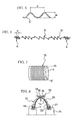
- FIG. 2 An example of a pneumatic tire manufactured with a method of manufacturing a pneumatic tire according to the present invention is shown in FIG. 2 .
- This pneumatic tire includes a tread portion 11, a right and a left sidewall portions 12, and a right and a left bead portions 13.
- Carcass plies 14 extend between the right and left bead portions 13, and have opposite end portions which are turned up around bead cores 17 embedded in the bead portions 13 from the inner side of the tire to the outer side thereof in such a manner that bead fillers 18 are sandwiched by the end portions.
- Belt plies 15 are disposed radailly outwardly of the carcass plies 14 in the tread portion 11.
- a belt cover ply 16 is provided radailly outwardly of the belt plies 15 as a belt-reinforcing layer.
- the belt cover ply 16 has a steel cord S' continuously shaped in a helical manner or in a manner of a two-dimensional wave.
- the steel cord S' is spirally wound at an angle of nearly 0° with respect to the circumferential direction of the tire in such a manner that stiffness of the belt cover ply 16 in the circumferential direction of the tire varies in the widthwise direction of the tire.
- a tread rubber layer 19 is placed radially outwardly of the belt cover ply.
- a side rubber layer 20 are disposed outward of the carcass plies 14 in each sidewall portion 12, and a cushion rubber layer 21 is provided in each bead portion 13.
- An innerliner 22 which acts as an air impermeable layer is placed inward of the carcass plies 14.
- Steps for manufacturing a pneumatic tire having a construction shown in FIG. 2 will be described below according to a method of manufacturing a pneumatic tire according to the present invention.
- the method of manufacturing a pneumatic tire according to the present invention is the same as the prior art method except for a step of forming a belt cover ply 16; therefore, the same steps as those of the prior art method will not be described in detail but will be described in brief.
- a first formed assembly 32 is formed on a first building drum 31 as in the prior art method. More specifically, an unvulcanized innerliner 22, unvulcanized carcass plies 14, bead cores 17 with unvulcanized bead fillers 18, unvulcanized cushion rubber layers 21, unvulcanized side rubber layers 20 are sequentially applied onto the first building drum 31 to form a first formed assembly 32.
- a second formed assembly 33 is formed on a second building drum (belt-forming drum) 4. More specifically, unvulcanized belt plies 15 are applied onto the second building drum 4 as in the prior art method. An unvulcanized belt cover ply 16 will then be formed on the unvulcanized belt plies 15 as below.
- a steel cord S which is not shaped is unwound from the feeding means 1 through the unwinding means 5 to feed it to the shaping means 2.
- the steel cord S is helically shaped by the rotating action of the rotating body 2a and the drawing action of the shaping pins 2b rotating.
- the shaping means 2 continuously shapes the steel cord S helically with its pitch P (see FIGS. 5 and 6 ) of shaping varying in a phased manner or in a continuous manner. Varying of the pitch P in a phased manner or in a continuous manner is performed by varying at least one of the rotation speed of the shaping pins 2b and the feeding speed of the steel cord S (the rotation speeds of the unwinding rolls 5a of the unwinding means 5 and the rollers 6a of the carrying means 6) in a phased manner or in a continuous manner.
- the steel cord is shaped such that portions A of the steel cord S' corresponding to opposite ends 16a of the belt cover ply 16 located on the opposite sides of the belt plies 15 have a shorter pitch P of shaping, and a portion B thereof corresponding to a middle portion 16b between the opposite ends 16a has a longer pitch of shaping.
- the steel cord S' continuously shaped by the shaping means 2 as described above is sequentially fed to the correcting means 3, where the steel cord S' is carried through the correcting rollers 3a, whereby it is uniformly corrected in helical shape.
- the corrected steel cord S' is sent to the traverse head 8a of the winding means 8 through the carrying means 6 and the tension-retaining means 7.
- the traverse head 8a While the traverse head 8a moves from one side of the second building drum 4 toward the other side thereof in the widthwise direction of the drum, the traverse head winds the helically shaped steel cord S' spirally in the circumferential direction of the drum around the belt plies 15 on the second building drum 4 rotating in such a manner that, while the circumferential stiffness of the belt cover ply 16 varies in the widthwise direction of the tire, the winding number of the steel cord S' per unit width of the belt cover ply 16 is substantially equal.
- the steel cord S' is wound such that the portions A having a shorter pitch P of shaping are disposed at locations of the opposite ends 16a of the belt cover ply 16 and the portion B having a longer pitch P is disposed at a location of the middle portion 16b of the belt cover ply 16.
- the traverse head 8a moves to the other side of the second building drum 4 in the widthwise direction of the drum, and there is formed on the belt plies 15 on the second building drum 4 a belt cover ply 16 (see FIG. 7 ) having the helically and continuously shaped steel cord S' wound spirally in the circumferential direction of the tire in such a manner that its circumferential stiffness varies in the widthwise direction of the tire.
- the belt cover ply 16 is shown in FIG. 7 in a simplified manner with the steel cord S' illustrated in straight line, but the steel cord S' is helically shaped in practice.
- An unvulcanized rubber sheet for coating the steel cord S' is wound around the formed belt cover ply 16 as required.
- it maybe arranged such that a process for coating the shaped steel cord S' with unvulcanized rubber is provided between the tension-retaining means 7 and the traverse head 8a, and the steel cord S' , which is coated with unvulcanized rubber in the process, is wound around the unvulcanized belt plies 15.
- an unvulcanized tread rubber layer 19 is applied onto the belt cover ply 16 to form a second formed assembly 33.
- a green tire is then built as in the prior art method. More specifically, while the first formed assembly 32 is removed from the first building drum 31, the second formed assembly 33 is removed from the second building drum 4.
- the first formed assembly 32 is mounted on a shaping drum 34 and is internally pressurized to give lift to the first formed assembly 32 as shown in FIG. 8 .
- This green tire is set in a tire-vulcanizing machine to vulcanize it, obtaining a pneumatic tire shown in FIG. 2 .
- the steel cord S is continuously shaped in a helical manner or in a manner of a two-dimensional wave just before application to thesecondbuildingdrum4, and the shaped steel cordS' is directly wound around the second building drum 4 to form the belt cover ply 16, thereby avoiding winding the shaped steel cord S' around a reel and housing it. Therefore, processes relating to housing of the shaped steel cord S' used for the belt cover ply 16 are eliminated, enabling tire productivity to be enhanced.
- the circumferential stiffness of the belt cover ply 16 can be changed in the widthwise direction of the tire without an increase in fatigue damage the steel cord S' accepts during winding.
- the shaping pitch P of the steel cord S' is changed in a phased manner or in a continuous manner; however, in the method of manufacturing a pneumatic tire according to the present invention, instead of that, the steel cord S may continuously be shaped in a helical manner or in a manner of a two-dimensional wave with its shaping amplitude W varying in a phased manner or in a continuous manner; the steel cord S may continuously be shaped in a helical manner or in a manner of a two-dimensional wave with at least one of the shaping amplitude W and pitch P varying in a phased manner or in a continuous manner.
- the belt-reinforcing layer As an example of the belt-reinforcing layer, a belt cover ply 16 is shown in the above embodiment.
- the belt-reinforcing layer referred in the present invention may be any reinforcing layer if the reinforcing layer is disposed radially outwardly of a carcass ply in the tread portion and has a structure of winding a steel cord spirally in the circumferential direction of the tire, preferably at an angle of nearly 0° with respect to the circumferential direction of the tire.
- the belt-reinforcing layer can include, for example, a belt ply having a structure of winding a steel cord spirally in the circumferential direction of the tire, preferably at an angle of nearly 0° with respect to the circumferential direction of the tire, and a reinforcing layer which is disposed radially inwardly of a belt ply or between belt plies and has the same structure.
- a pneumatic tire having such a belt-reinforcing layer may be manufactured with the method of manufacturing a pneumatic tire according to the present invention.
- the above-mentioned steel cord S may be a steel cord having a plurality of steel filaments twisted with each other or a single wire steel cord formed from one steel wire.
- the present invention is preferably applicable to a method of manufacturing a pneumatic tire including a belt-reinforcing layer arranged so as to vary its circumferential stiffness in the widthwise direction of the tire with the winding number of the shaped steel cord S' per unit width being substantially equal.
- the present invention can also be applied to a method of manufacturing a pneumatic tire including a belt-reinforcing layer the shaped steel cord S' of which is wound in such a manner that the winding number per unit width is different, as is obvious.
- the method of manufacturing a pneumatic tire according to the present invention having the aforementioned excellent effect can be utilized to manufacture a pneumatic tire having a belt-reinforcing layer in which a steel cord which is continuously shaped in a helical manner or in a manner of a two-dimensional wave is spirally wound in such a manner that its circumferential stiffness varies in the widthwise direction of the tire.
Landscapes
- Engineering & Computer Science (AREA)
- Mechanical Engineering (AREA)
- Tyre Moulding (AREA)
- Tires In General (AREA)
Applications Claiming Priority (2)
| Application Number | Priority Date | Filing Date | Title |
|---|---|---|---|
| JP2006085325A JP4866123B2 (ja) | 2006-03-27 | 2006-03-27 | 空気入りタイヤの製造方法 |
| PCT/JP2007/055560 WO2007119429A1 (ja) | 2006-03-27 | 2007-03-19 | 空気入りタイヤの製造方法 |
Publications (4)
| Publication Number | Publication Date |
|---|---|
| EP2000291A2 true EP2000291A2 (de) | 2008-12-10 |
| EP2000291A9 EP2000291A9 (de) | 2009-03-25 |
| EP2000291A4 EP2000291A4 (de) | 2010-06-02 |
| EP2000291B1 EP2000291B1 (de) | 2014-04-23 |
Family
ID=38609219
Family Applications (1)
| Application Number | Title | Priority Date | Filing Date |
|---|---|---|---|
| EP07739003.7A Ceased EP2000291B1 (de) | 2006-03-27 | 2007-03-19 | Verfahren zur herstellung eines luftreifens |
Country Status (4)
| Country | Link |
|---|---|
| US (1) | US20090084489A1 (de) |
| EP (1) | EP2000291B1 (de) |
| JP (1) | JP4866123B2 (de) |
| WO (1) | WO2007119429A1 (de) |
Cited By (3)
| Publication number | Priority date | Publication date | Assignee | Title |
|---|---|---|---|---|
| FR3030349A1 (fr) * | 2014-12-23 | 2016-06-24 | Michelin & Cie | Dispositif et procede pour la fabrication de pneumatiques |
| EP3023264A4 (de) * | 2013-07-15 | 2017-03-15 | Hongduk Industrial Co. Ltd. | Stahlseil zur reifenverstärkung |
| CN106660286A (zh) * | 2014-06-30 | 2017-05-10 | 米其林集团总公司 | 用于组装轮胎胎坯的方法和装置 |
Families Citing this family (3)
| Publication number | Priority date | Publication date | Assignee | Title |
|---|---|---|---|---|
| KR100916917B1 (ko) * | 2007-11-06 | 2009-09-09 | 주식회사 효성 | 단선 스틸코드 |
| EP2283998A4 (de) * | 2008-06-04 | 2012-07-04 | Bridgestone Corp | Verfahren und vorrichtung zur herstellung eines reifens |
| FR3022833B1 (fr) | 2014-06-30 | 2017-03-10 | Michelin & Cie | Dispositif et procede pour la preparation d'une bandelette de renforcement destinee a la fabrication de pneumatiques |
Family Cites Families (22)
| Publication number | Priority date | Publication date | Assignee | Title |
|---|---|---|---|---|
| US3682222A (en) | 1970-01-06 | 1972-08-08 | Steelastic Co | Pneumatic tire having helical reinforcing filaments |
| IT1125578B (it) | 1979-10-24 | 1986-05-14 | Pirelli | Perfezionamento alle strutture anulari di rinforzo per pneumatici radiali |
| EP0524703B1 (de) * | 1987-06-18 | 1996-08-21 | Sumitomo Rubber Industries Limited | Einrichtung zur Herstellung eines Gürtels für Radial-Reifen |
| US5271445A (en) * | 1988-09-19 | 1993-12-21 | Bridgestone Corporation | Pneumatic tire including wave-shaped cords or filaments |
| JPH06191219A (ja) | 1992-12-25 | 1994-07-12 | Bridgestone Corp | 重荷重用空気入りラジアルタイヤ |
| JPH06255310A (ja) * | 1993-03-08 | 1994-09-13 | Sumitomo Rubber Ind Ltd | 自動二輪車用ラジアルタイヤ |
| JP3466736B2 (ja) * | 1994-11-02 | 2003-11-17 | 株式会社ブリヂストン | 空気入りタイヤ |
| JP3723258B2 (ja) * | 1995-12-08 | 2005-12-07 | 株式会社ブリヂストン | 空気入りラジアルタイヤ |
| FR2744954B1 (fr) | 1996-02-20 | 1998-03-20 | Michelin & Cie | Armature de sommet pour pneumatique "poids-lourds" |
| GB9603948D0 (en) * | 1996-02-24 | 1996-04-24 | Sumitomo Rubber Ind | Reinforcement ply and method of manufacture |
| WO1997039176A1 (en) * | 1996-04-18 | 1997-10-23 | Bridgestone Corporation | Rubber article reinforcing steel cord and pneumatic tire |
| JP3976373B2 (ja) | 1997-06-20 | 2007-09-19 | 株式会社ブリヂストン | 空気入りタイヤの製造方法 |
| JP2000052711A (ja) * | 1998-08-06 | 2000-02-22 | Bridgestone Corp | 重荷重用空気入りラジアルタイヤ及びその製造方法 |
| JP2000129583A (ja) | 1998-10-16 | 2000-05-09 | Yokohama Rubber Co Ltd:The | スチールコード及びこれを用いた空気入りラジアルタイヤ |
| JP2000255214A (ja) | 1999-03-03 | 2000-09-19 | Yokohama Rubber Co Ltd:The | 乗用車用空気入りラジアルタイヤ |
| EP1066989B1 (de) | 1999-07-07 | 2006-11-15 | Sumitomo Rubber Industries Ltd. | Luftreifen |
| JP4597400B2 (ja) | 2001-02-28 | 2010-12-15 | 金井 宏彰 | 単線スチールコードの製造方法及びその装置 |
| JP2002294573A (ja) * | 2001-03-30 | 2002-10-09 | Tokusen Kogyo Co Ltd | タイヤ補強用スチールコード及びタイヤ |
| DE60238610D1 (de) | 2001-07-19 | 2011-01-27 | Pirelli | Reifen für kraftfahrzeuge mit gewellten monofilamenten in gürtelverstärkungsschicht |
| DE10138670B4 (de) * | 2001-08-07 | 2005-03-10 | Continental Ag | Fahrzeugluftreifen mit einer Gürtelbandage |
| JP3952150B2 (ja) * | 2002-02-06 | 2007-08-01 | 横浜ゴム株式会社 | ゴム・スチールワイヤ複合部材の製造方法及びその装置 |
| JP4309339B2 (ja) * | 2002-05-29 | 2009-08-05 | ソシエテ ド テクノロジー ミシュラン | ストリップを回転表面に取り付けるための装置および方法 |
-
2006
- 2006-03-27 JP JP2006085325A patent/JP4866123B2/ja not_active Expired - Fee Related
-
2007
- 2007-03-19 US US12/282,433 patent/US20090084489A1/en not_active Abandoned
- 2007-03-19 WO PCT/JP2007/055560 patent/WO2007119429A1/ja not_active Ceased
- 2007-03-19 EP EP07739003.7A patent/EP2000291B1/de not_active Ceased
Cited By (5)
| Publication number | Priority date | Publication date | Assignee | Title |
|---|---|---|---|---|
| EP3023264A4 (de) * | 2013-07-15 | 2017-03-15 | Hongduk Industrial Co. Ltd. | Stahlseil zur reifenverstärkung |
| CN106660286A (zh) * | 2014-06-30 | 2017-05-10 | 米其林集团总公司 | 用于组装轮胎胎坯的方法和装置 |
| CN106660286B (zh) * | 2014-06-30 | 2018-12-11 | 米其林集团总公司 | 用于组装轮胎胎坯的方法和装置 |
| FR3030349A1 (fr) * | 2014-12-23 | 2016-06-24 | Michelin & Cie | Dispositif et procede pour la fabrication de pneumatiques |
| WO2016102614A1 (fr) * | 2014-12-23 | 2016-06-30 | Compagnie Generale Des Etablissements Michelin | Dispositif et procede pour la fabrication de pneumatiques |
Also Published As
| Publication number | Publication date |
|---|---|
| JP4866123B2 (ja) | 2012-02-01 |
| EP2000291B1 (de) | 2014-04-23 |
| US20090084489A1 (en) | 2009-04-02 |
| EP2000291A4 (de) | 2010-06-02 |
| EP2000291A9 (de) | 2009-03-25 |
| WO2007119429A1 (ja) | 2007-10-25 |
| JP2007260931A (ja) | 2007-10-11 |
Similar Documents
| Publication | Publication Date | Title |
|---|---|---|
| JP4695429B2 (ja) | 空気入りタイヤ及びその製造方法 | |
| EP2516145B1 (de) | Geodätischer reifen und verfahren zu seiner herstellung | |
| US8815032B2 (en) | Method for producing a tread rubber for a vehicle tire, in particular a pneumatic vehicle tire | |
| US8211258B2 (en) | Method and device for producing a tread for a vehicle tire | |
| EP2000291A2 (de) | Verfahren zur herstellung eines luftreifens | |
| JPH09323504A (ja) | エラストマ製品用の補強プライ及びその製造方法 | |
| US7431063B2 (en) | Method for producing a belt structure for a vehicle tyre and vehicle tyre including the belt structure | |
| JP2010095057A (ja) | 空気入りタイヤ及びその製造方法 | |
| JP5255635B2 (ja) | タイヤの製造方法および装置 | |
| JP4939344B2 (ja) | 空気入りタイヤ、及びその製造方法 | |
| JP4381609B2 (ja) | 自動車用タイヤのカーカス構造体の製造方法、及びそのカーカス構造体 | |
| CN100455452C (zh) | 用于车轮的轮胎及其制造方法 | |
| JP2007069408A (ja) | 空気入りタイヤの製造方法及び空気入りタイヤ | |
| JP4807976B2 (ja) | 空気入りタイヤおよびその製造方法 | |
| KR101141032B1 (ko) | 고무용 보강재, 당해 보강재를 사용하는 고무 제품 및 당해고무 제품의 제조방법, 및 당해 보강재를 사용하는 공기타이어 및 당해 타이어의 제조방법 | |
| WO2014073303A1 (ja) | 空気入りタイヤ、及びその製造方法 | |
| JP5204442B2 (ja) | 空気入りタイヤ、及びその製造方法 | |
| JP2011083971A (ja) | 自動二輪車用タイヤの製造方法、およびそれによって製造された自動二輪車用タイヤ | |
| JP3735445B2 (ja) | 空気入りラジアルタイヤ | |
| JP2001055676A (ja) | ゴム物品補強用スチールコードおよびその製造方法並びに空気入りタイヤ | |
| KR20050123168A (ko) | 차량 바퀴용 타이어 및 이의 제조 방법 | |
| EP1787827A1 (de) | Luftreifen mit nach unten umgeschlagener Karkasse und Verfahren zur Herstellung eines derartigen Luftreifens | |
| JP2005186297A (ja) | 中空ゴムローラー及びその製造方法 | |
| JP2005035335A (ja) | 空気入りタイヤ |
Legal Events
| Date | Code | Title | Description |
|---|---|---|---|
| PUAI | Public reference made under article 153(3) epc to a published international application that has entered the european phase |
Free format text: ORIGINAL CODE: 0009012 |
|
| 17P | Request for examination filed |
Effective date: 20081016 |
|
| AK | Designated contracting states |
Kind code of ref document: A2 Designated state(s): FR |
|
| PUAB | Information related to the publication of an a document modified or deleted |
Free format text: ORIGINAL CODE: 0009199EPPU |
|
| DAX | Request for extension of the european patent (deleted) | ||
| RBV | Designated contracting states (corrected) |
Designated state(s): FR |
|
| A4 | Supplementary search report drawn up and despatched |
Effective date: 20100503 |
|
| RIC1 | Information provided on ipc code assigned before grant |
Ipc: B29D 30/30 20060101AFI20080114BHEP Ipc: B60C 9/18 20060101ALI20100426BHEP |
|
| 17Q | First examination report despatched |
Effective date: 20120210 |
|
| GRAP | Despatch of communication of intention to grant a patent |
Free format text: ORIGINAL CODE: EPIDOSNIGR1 |
|
| INTG | Intention to grant announced |
Effective date: 20131031 |
|
| GRAS | Grant fee paid |
Free format text: ORIGINAL CODE: EPIDOSNIGR3 |
|
| GRAA | (expected) grant |
Free format text: ORIGINAL CODE: 0009210 |
|
| RIN1 | Information on inventor provided before grant (corrected) |
Inventor name: MORIOKA, NORITAKA Inventor name: HARIKAE, SHINYA |
|
| AK | Designated contracting states |
Kind code of ref document: B1 Designated state(s): FR |
|
| PLBE | No opposition filed within time limit |
Free format text: ORIGINAL CODE: 0009261 |
|
| STAA | Information on the status of an ep patent application or granted ep patent |
Free format text: STATUS: NO OPPOSITION FILED WITHIN TIME LIMIT |
|
| 26N | No opposition filed |
Effective date: 20150126 |
|
| REG | Reference to a national code |
Ref country code: FR Ref legal event code: PLFP Year of fee payment: 10 |
|
| REG | Reference to a national code |
Ref country code: FR Ref legal event code: PLFP Year of fee payment: 11 |
|
| REG | Reference to a national code |
Ref country code: FR Ref legal event code: PLFP Year of fee payment: 12 |
|
| PGFP | Annual fee paid to national office [announced via postgrant information from national office to epo] |
Ref country code: FR Payment date: 20210210 Year of fee payment: 15 |
|
| PG25 | Lapsed in a contracting state [announced via postgrant information from national office to epo] |
Ref country code: FR Free format text: LAPSE BECAUSE OF NON-PAYMENT OF DUE FEES Effective date: 20220331 |