EP1997579A1 - Fülldraht für das verbinden von verschiedenen materialien und verfahren zum verbinden verschiedener materialien - Google Patents
Fülldraht für das verbinden von verschiedenen materialien und verfahren zum verbinden verschiedener materialien Download PDFInfo
- Publication number
- EP1997579A1 EP1997579A1 EP07713870A EP07713870A EP1997579A1 EP 1997579 A1 EP1997579 A1 EP 1997579A1 EP 07713870 A EP07713870 A EP 07713870A EP 07713870 A EP07713870 A EP 07713870A EP 1997579 A1 EP1997579 A1 EP 1997579A1
- Authority
- EP
- European Patent Office
- Prior art keywords
- flux
- welding
- joining
- fluoride
- aluminum
- Prior art date
- Legal status (The legal status is an assumption and is not a legal conclusion. Google has not performed a legal analysis and makes no representation as to the accuracy of the status listed.)
- Granted
Links
Images


Classifications
-
- B—PERFORMING OPERATIONS; TRANSPORTING
- B23—MACHINE TOOLS; METAL-WORKING NOT OTHERWISE PROVIDED FOR
- B23K—SOLDERING OR UNSOLDERING; WELDING; CLADDING OR PLATING BY SOLDERING OR WELDING; CUTTING BY APPLYING HEAT LOCALLY, e.g. FLAME CUTTING; WORKING BY LASER BEAM
- B23K9/00—Arc welding or cutting
- B23K9/23—Arc welding or cutting taking account of the properties of the materials to be welded
-
- B—PERFORMING OPERATIONS; TRANSPORTING
- B23—MACHINE TOOLS; METAL-WORKING NOT OTHERWISE PROVIDED FOR
- B23K—SOLDERING OR UNSOLDERING; WELDING; CLADDING OR PLATING BY SOLDERING OR WELDING; CUTTING BY APPLYING HEAT LOCALLY, e.g. FLAME CUTTING; WORKING BY LASER BEAM
- B23K35/00—Rods, electrodes, materials, or media, for use in soldering, welding, or cutting
- B23K35/02—Rods, electrodes, materials, or media, for use in soldering, welding, or cutting characterised by mechanical features, e.g. shape
- B23K35/0255—Rods, electrodes, materials, or media, for use in soldering, welding, or cutting characterised by mechanical features, e.g. shape for use in welding
- B23K35/0261—Rods, electrodes, wires
- B23K35/0266—Rods, electrodes, wires flux-cored
-
- B—PERFORMING OPERATIONS; TRANSPORTING
- B23—MACHINE TOOLS; METAL-WORKING NOT OTHERWISE PROVIDED FOR
- B23K—SOLDERING OR UNSOLDERING; WELDING; CLADDING OR PLATING BY SOLDERING OR WELDING; CUTTING BY APPLYING HEAT LOCALLY, e.g. FLAME CUTTING; WORKING BY LASER BEAM
- B23K35/00—Rods, electrodes, materials, or media, for use in soldering, welding, or cutting
- B23K35/22—Rods, electrodes, materials, or media, for use in soldering, welding, or cutting characterised by the composition or nature of the material
- B23K35/36—Selection of non-metallic compositions, e.g. coatings, fluxes; Selection of soldering or welding materials, conjoint with selection of non-metallic compositions, both selections being of interest
- B23K35/362—Selection of compositions of fluxes
-
- B—PERFORMING OPERATIONS; TRANSPORTING
- B23—MACHINE TOOLS; METAL-WORKING NOT OTHERWISE PROVIDED FOR
- B23K—SOLDERING OR UNSOLDERING; WELDING; CLADDING OR PLATING BY SOLDERING OR WELDING; CUTTING BY APPLYING HEAT LOCALLY, e.g. FLAME CUTTING; WORKING BY LASER BEAM
- B23K35/00—Rods, electrodes, materials, or media, for use in soldering, welding, or cutting
- B23K35/22—Rods, electrodes, materials, or media, for use in soldering, welding, or cutting characterised by the composition or nature of the material
- B23K35/36—Selection of non-metallic compositions, e.g. coatings, fluxes; Selection of soldering or welding materials, conjoint with selection of non-metallic compositions, both selections being of interest
- B23K35/368—Selection of non-metallic compositions of core materials either alone or conjoint with selection of soldering or welding materials
-
- B—PERFORMING OPERATIONS; TRANSPORTING
- B23—MACHINE TOOLS; METAL-WORKING NOT OTHERWISE PROVIDED FOR
- B23K—SOLDERING OR UNSOLDERING; WELDING; CLADDING OR PLATING BY SOLDERING OR WELDING; CUTTING BY APPLYING HEAT LOCALLY, e.g. FLAME CUTTING; WORKING BY LASER BEAM
- B23K35/00—Rods, electrodes, materials, or media, for use in soldering, welding, or cutting
- B23K35/40—Making wire or rods for soldering or welding
- B23K35/406—Filled tubular wire or rods
-
- B—PERFORMING OPERATIONS; TRANSPORTING
- B23—MACHINE TOOLS; METAL-WORKING NOT OTHERWISE PROVIDED FOR
- B23K—SOLDERING OR UNSOLDERING; WELDING; CLADDING OR PLATING BY SOLDERING OR WELDING; CUTTING BY APPLYING HEAT LOCALLY, e.g. FLAME CUTTING; WORKING BY LASER BEAM
- B23K9/00—Arc welding or cutting
- B23K9/16—Arc welding or cutting making use of shielding gas
- B23K9/173—Arc welding or cutting making use of shielding gas and of a consumable electrode
-
- B—PERFORMING OPERATIONS; TRANSPORTING
- B23—MACHINE TOOLS; METAL-WORKING NOT OTHERWISE PROVIDED FOR
- B23K—SOLDERING OR UNSOLDERING; WELDING; CLADDING OR PLATING BY SOLDERING OR WELDING; CUTTING BY APPLYING HEAT LOCALLY, e.g. FLAME CUTTING; WORKING BY LASER BEAM
- B23K9/00—Arc welding or cutting
- B23K9/23—Arc welding or cutting taking account of the properties of the materials to be welded
- B23K9/232—Arc welding or cutting taking account of the properties of the materials to be welded of different metals
-
- B—PERFORMING OPERATIONS; TRANSPORTING
- B23—MACHINE TOOLS; METAL-WORKING NOT OTHERWISE PROVIDED FOR
- B23K—SOLDERING OR UNSOLDERING; WELDING; CLADDING OR PLATING BY SOLDERING OR WELDING; CUTTING BY APPLYING HEAT LOCALLY, e.g. FLAME CUTTING; WORKING BY LASER BEAM
- B23K2101/00—Articles made by soldering, welding or cutting
- B23K2101/18—Sheet panels
-
- B—PERFORMING OPERATIONS; TRANSPORTING
- B23—MACHINE TOOLS; METAL-WORKING NOT OTHERWISE PROVIDED FOR
- B23K—SOLDERING OR UNSOLDERING; WELDING; CLADDING OR PLATING BY SOLDERING OR WELDING; CUTTING BY APPLYING HEAT LOCALLY, e.g. FLAME CUTTING; WORKING BY LASER BEAM
- B23K2103/00—Materials to be soldered, welded or cut
- B23K2103/18—Dissimilar materials
- B23K2103/20—Ferrous alloys and aluminium or alloys thereof
-
- Y—GENERAL TAGGING OF NEW TECHNOLOGICAL DEVELOPMENTS; GENERAL TAGGING OF CROSS-SECTIONAL TECHNOLOGIES SPANNING OVER SEVERAL SECTIONS OF THE IPC; TECHNICAL SUBJECTS COVERED BY FORMER USPC CROSS-REFERENCE ART COLLECTIONS [XRACs] AND DIGESTS
- Y10—TECHNICAL SUBJECTS COVERED BY FORMER USPC
- Y10T—TECHNICAL SUBJECTS COVERED BY FORMER US CLASSIFICATION
- Y10T428/00—Stock material or miscellaneous articles
- Y10T428/12—All metal or with adjacent metals
- Y10T428/12493—Composite; i.e., plural, adjacent, spatially distinct metal components [e.g., layers, joint, etc.]
- Y10T428/12736—Al-base component
- Y10T428/1275—Next to Group VIII or IB metal-base component
- Y10T428/12757—Fe
Definitions
- the invention relates to a flux cored wire (FCW: Flux Cored Wire) for joining dissimilar materials with each other, that is, a steel-base material and an aluminum-base material with each other, and a method for joining the dissimilar materials with each other.
- FCW Flux Cored Wire
- a technology according to the invention is suitably applicable to automobiles, railway vehicles, and so forth, in the transportation field, machine components, construction members such as building structures, and so forth. The technology is required in the assembling process for automobile structures.
- the steel member In the case of joining dissimilar materials such as the steel member and the aluminum member with each other, the steel member is high in melting point, and electrical resistance, but low in thermal conductivity, as compared with the aluminum member, so that heat evolution on the steel side of a joint will be greater, thereby causing aluminum lower in melting point to be first fused.
- the surface of the steel member undergoes fusion, resulting in formation of a brittle intermetallic compound of Fe-Al series on an interface therebetween. As a result, it is not possible to obtain a high bonding strength.
- Patent Document 1 a method for joining the dissimilar materials together by rolling the same in a vacuum has been proposed.
- Patent Document 2 a method for making seam welds by interposing a two-layer cladding material made up of a steel-base material layer and an aluminum alloy layer, prepared beforehand.
- Patent Document 3 a method for pressure joining at a high temperature.
- Patent Documents 4 and 5 there has been proposed a method for joining by HIP treatment by interposing a Ti alloy placed on respective joint surfaces.
- Patent Document 6 there has been proposed a method for friction welding (refer to Patent Document 6). Then, there has been proposed a method whereby resistance welding is carried out by plating the surface of a steel material layer, in contact with aluminum, with an aluminum alloy beforehand, or by interposing the two-layer cladding material made up of the steel-base material layer and the aluminum alloy layer, prepared beforehand (refer to Patent Documents 7, and 8).
- Non-patent Documents 1, 2, and 3 there has been proposed a method for line-joining or face-joining the steel material with the aluminum material by arc welding (refer to Non-patent Documents 1, 2, and 3). Further, there has also been proposed a method for joining the steel material directly with the aluminum material by MIG brazing in order to secure a sound bonded joint (refer to Patent Document 9).
- Non-patent Documents 1, 2, 3, and so forth With the method for joining the steel material with the aluminum material by arc welding, as described in Non-patent Documents 1, 2, 3, and so forth, holes are provided on the steel material side of a joint beforehand, and a growth direction of an intermetallic compound acting as a factor for blocking securing of strength is controlled by filling up the holes with the aluminum material, thereby attempting to obtain a high bonding strength.
- a growth direction of an intermetallic compound acting as a factor for blocking securing of strength is controlled by filling up the holes with the aluminum material, thereby attempting to obtain a high bonding strength.
- cracking is prone to occur to beads in the case of continuous arc welding, so that a welded joint still has a room for improvement in strength.
- Patent Document 9 The same applied to Patent Document 9.
- Patent Documents 10, 11 there has been proposed a method for brazing at a low temperature so as to prevent a brittle Fe-Al intermetallic compound from being generated at a joint.
- the joint of the dissimilar materials (welded joint of the dissimilar materials) formed by weld-bonding the steel member with the aluminum member is put to use as structural members of the automobile, and so forth, the joint needs strength capable of withstanding a load (stress) imposed thereon at the time of automobile collision, and so forth.
- Those structural members of the automobile include, for example, the bonded joints of the dissimilar materials such as side members made up of the steel members, bumper stay (a bonded member on the rear side of a bumper reinforcement), and so forth.
- the bonded joints of the dissimilar materials according to those conventional techniques described in the foregoing, respectively, however, are found lacking in bonding strength if such application as described is assumed, and still have a room for improvement.
- spot welding With the spot welding, a joint is confined to a relatively small portion of the area of the joint, so that it is not possible to obtain a continuous joint.
- the spot welding is therefore efficient, and suitable for use in joining panels with each other, but is unsuitable for line welding, such as fillet welding, butt welding, and so forth, required of bimetallic joining for the structural members of the automobile.
- brazing by use of a solder of aluminum base, or by use of flux and the solder of aluminum base has been carried out.
- a joining temperature range for members to be joined together needs be strictly controlled so as to be not lower than the melting temperature of the solder, and not higher than the melting temperature of the members to be joined together.
- the brazing at low temperatures cannot be applied to the joining of the large sized members such as the automobile body to require design freedom of the shape of a joint, and so forth because it takes long time to implement joining by so doing.
- the fluoride-based mixed flux composed of a mixture containing aluminum fluoride, and potassium fluoride, originally having a melting point lower than that of aluminum, and cesium fluoride low in melting point, added to the mixture, will have a melting point thereof further lowered. Accordingly, there arises a problem in that a large amount of the flux undergoes evaporation at the time of welding, so that not only deterioration of workability results due to evolution of fume, and spattering, and so forth, but also a high bonding strength cannot be obtained because weld metal composed of aluminum is excessively spread, thereby preventing formation of a sound bead.
- the invention has been developed to solve those problems described. It is an object of the invention to provide a flux cored wire for joining dissimilar materials with each other, capable of enhancing a bonding strength in melt weld-bonding of the high-strength dissimilar materials with each other, that is, the high-strength steel member with the high-strength 6000 series aluminum alloy member, in particular, and excellent in welding efficiency, and to provide a method for joining the dissimilar materials with each other.
- Another object of the invention is to provide a joining method capable of obtaining a high bonding strength by preventing formation of a brittle intermetallic compound at a joint when joining an aluminum-base material with a steel-base material while forming a sound bead and to provide a bonded joint obtained by the method.
- the invention is intended to enable continuous joining to be implemented by use of the method according to the invention, the continuous joining being under fewer constraints in geometrics and excellent in workability besides being under fewer constraints in application conditions, and so forth, and excellent in general versatility.
- a flux cored wire for joining dissimilar materials together comprising a flux used for joining of dissimilar materials including an aluminum member or an aluminum alloy member and a steel member, with each other and an aluminum alloy envelope, the interior thereof being filled up with the flux, wherein the flux has fluoride composition containing AlF 3 in a range of 0.1 to 15 mass % against the total mass of the flux cored wire without containing chloride. Further, the flux in a range of 0.3 to 20 mss % against the total mass of the flux cored is preferably filled in the interior of the aluminum alloy envelope.
- an aluminum alloy of the envelope preferably contains Si in a range of 1 to 13 mass %, the balance being composed of Al and unavoidable impurities.
- the aluminum alloy of the envelope preferably further contains Mn in a range of 0.1 to 0.3 mass %.
- the steel member is preferably a galvanized steel member.
- the flux cored wire according to the invention is applied to joining of a high tensile steel member with a 6000 series aluminum alloy member, this is particularly preferable.
- a method for joining dissimilar materials together comprising the step of melt-welding the dissimilar materials including a high tensile steel member and a 6000 series aluminum alloy member, with each other, by use of the flux cored wire of preferred modes described above, or described above and to be described later.
- a method for joining dissimilar materials together comprising the step of an AC - MIG welding for directly joining an aluminum member or an aluminum alloy member with a steel member by use of a flux cored wire formed by coating a flux containing potassium fluoride, aluminum fluoride, and at least one fluoride selected from the group consisting of magnesium fluoride, calcium fluoride, strontium fluoride, and barium fluoride with aluminum or an aluminum alloy, as a filler metal.
- the steel member described as above is preferably a galvanized steel member.
- a bonded joint wherein a steel based member is joined with an aluminum based member by any of the methods for joining dissimilar materials together, described in the foregoing.
- a method for joining dissimilar materials together may comprises the step of joining an aluminum member or an aluminum alloy member with a steel member by either an AC - MIG welding or a MIG welding by DC reversed polarity with the use of a flux cored wire, wherein the flux cored wire is formed by filling up the interior of an envelope made up of an aluminum member or an aluminum alloy member with a flux, the flux for filling up is mixed with aluminum fluoride, and potassium fluoride to be turned into a mixed flux, and a loading weight of the mixed flux is in a range of 0.1 to 24 mass %, against the total mass of the flux cored wire.
- the method for joining dissimilar materials together is preferably applied to a galvanized steel member such as a hot-dip galvanized steel sheet, relatively large in plating thickness, poorer in weldability than a bare steel, and exhibiting pronounced deterioration in bonding strength, and so forth,
- the mixed flux described as above preferably has a melting point in a range of 560 to 700°C, and the flux cored wire is preferably not more than 1.6 mm ⁇ in diameter.
- the flux used in the melt weld-bonding of dissimilar materials with each other is required to have not only effects of removing an oxide film formed on the surface of a member to be welded, such as an aluminum alloy member, by reduction, but also effects of checking growth of an Fe-Al intermetallic compound layer generated in a weld zone of the steel member.
- the flux used in the melt weld-bonding of the dissimilar materials with each other is required to act on the surface of the steel member, thereby fulfilling a function for blocking interdiffusion between Fe and Al.
- the inventor, et al. have found out that effects of an action for blocking the interdiffusion between Fe and Al are profoundly exhibited in a flux of fluoride composition, or fluoride-base, particularly, in a flux containing AlF 3 (aluminum fluoride).
- a flux of fluoride composition not containing AlF 3 is small in the effects of the action for blocking the interdiffusion between Fe and Al as compared with the flux of the fluoride composition containing AlF 3 .
- the flux of fluoride composition not containing AlF 3 is capable of enhancing a bonding strength in melt weld-bonding of low-strength dissimilar materials with each other, but cannot enhance the bonding strength up to the reliability level, and the practicality level in the melt weld-bonding of the high-strength dissimilar materials with each other, such as the high-strength steel member and the high-strength 6000 series aluminum alloy member with each other.
- the specific compound formed on the surface of the steel member acts so as to delay a time when the Fe-Al intermetallic compound layer (an interfacial reaction layer) is formed between the steel member and the aluminum alloy member, so that direct joining of Fe and Al, along with progress in the melt welding, will not be blocked.
- the invention provides the flux cored wire using the flux of fluoride composition containing AlF 3 , the flux being filled in the interior of the envelope. Accordingly, the invention has excellent effects of providing an aggregate of dissimilar materials joined, and the method for joining dissimilar materials together, capable of enhancing a bonding strength in melt weld-bonding of high-strength dissimilar materials with each other, in particular, the high-strength steel member with the high-strength 6000 series aluminum alloy member, and excellent in welding efficiency.
- the flux containing aluminum fluoride and potassium fluoride, with addition of high melting point fluorides is used as a filler material, thereby checking evaporation of the flux at the time of welding, and improving workability.
- the flux By use of the flux, excessive spread of a weld metal composed of aluminum is checked, thereby forming a sound bead, and generation of the brittle intermetallic compound at a joint is prevented, so that it is possible to obtain a high bonding strength.
- this method has fewer constraints in application conditions, and so forth, excellent general versatility, fewer constraints in geometrics, and capability of continuous joining, so that joining of an aluminum base member with a steel base member can be efficiently implemented.
- a mixed flux of a specified composition, mixed with aluminum fluoride, and potassium fluoride, among fluoride-based mixed fluxes use is made of a mixed flux of a specified composition, mixed with aluminum fluoride, and potassium fluoride, among fluoride-based mixed fluxes.
- the loading weight of the mixed flux is set relatively small to fall in a range of 0.1 to 24 mass %, against the total mass of the flux cored wire.
- the invention when an aluminum member is joined with a steel member, there are fewer constraints in application conditions, and so forth, excellent general versatility, and fewer constraints in geometrics. Furthermore, it is possible to provide a joining technology whereby continuous joining, necessary in the case of line welding, is enabled, generation of the brittle Fe-Al intermetallic compound at a joint, and occurrence of blowholes in the weld zone are reduced, deterioration in corrosion resistance is less, and welding workability is improved. Accordingly, the invention can provide a bonded joint of dissimilar materials (welded joint of dissimilar materials) applicable to structural members of the automobile, and so forth.
- a flux cored wire for use in joining dissimilar materials together is a flux cored wire covered with a tubular envelope (also called a hoop) filled up with a flux in order to enhance efficiency in melt-welding.
- the flux cored wire has an advantage in its applicability for melt-welding in the case of either highly efficient fully automatic welding, or semiautomatic welding.
- a wire diameter of the flux cored wire it need only be sufficient to select an optimum diameter according to welding workability including the characteristics of a wire feeder, for use in execution of welding in the case of either the highly efficient fully automatic welding, or the semiautomatic welding, and so forth.
- a wire feeder for use in execution of welding in the case of either the highly efficient fully automatic welding, or the semiautomatic welding, and so forth.
- use may be made of a small diameter on the order of 0.8 to 1.6 mm ⁇ for general purpose use.
- a formed wire tubular in shape is first fabricated by a process comprising the steps of forming an aluminum alloy hoop for the envelope into a shape resembling the letter U, filling up a formed hoop in the shape resembling the letter U with a flux, forming a U-shaped hoop into a tubular wire, and so forth. Thereafter, the flux cored wire can be manufactured by a common manufacturing method comprising the step of drawing the formed wire tubular in shape so as to have a product FCW diameter.
- the flux cored wire (hereinafter referred to merely as a wire, or an FCW) generally includes a type having a line of juncture (crevice, opening: hereinafter referred to also as a seam) on the hoop, and a seamless type having no crevice (without the line of juncture), fabricated by sealing a line of juncture by welding and so forth.
- a line of juncture crevice, opening: hereinafter referred to also as a seam
- a seamless type having no crevice without the line of juncture
- an aluminum alloy making up the envelope preferably contains Si in a range of 1 to 13 mass %, the balance being composed of Al and unavoidable impurities.
- the main reason for this is because of necessity of securing fluidity of aluminum alloy in a molten state, the strength of a joint after solidification, the strength of the envelope, and so forth. If Si content is too low, this will cause deterioration in the fluidity, and strength. On the contrary, if Si content excessively increases, this will cause weld metal to be more prone to be brittle besides a tendency of enhancement in the fluidity reaching saturation. Hence, if Si is to be contained, the Si content is to fall in the range of 1 to 13 mass %.
- the envelope needs strength, in which the envelope preferably has Si content in a range of 9 to 13 mass %.
- the aluminum alloy making up the envelope preferably further contains Mn in a range of 0.1 to 0.3 mass %, in addition to Si, the balance being composed of Al and unavoidable impurities.
- Mn in a range of 0.1 to 0.3 mass %, in addition to Si, the balance being composed of Al and unavoidable impurities.
- the main reason for this is because of necessity of further securing the fluidity of the aluminum alloy in the molten state, the strength of the joint after solidification, the strength of the envelope, and so forth. If Mn content is too low, those effects described are not obtained. On the contrary, if Mn content excessively increases, this will cause the weld metal to be more prone to be brittle besides the tendency of enhancement in the fluidity reaching saturation. Hence, if Mn is to be contained, the Mn content is to fall in the range of 0.1 to 0.3 mass %.
- an aluminum alloy filler metal standardized for general use.
- use is preferably made of an A4047 type containing Si in a range of 11.0 to 13.0 mass %, and not more than 0.15 mass % of Mn.
- use can be also made of an A4043 type containing Si in a range of 4.5 to 6.0 mass %, and not more than 0.05 mass % of Mn.
- the flux filled in the interior of the envelope is assumed to have fluoride composition without containing chloride. If a chloride remains in a weld zone, the chloride acts as a factor for promotion of corrosion of the weld zone, or the aggregate of the dissimilar materials joined, and therefore, chloride content is to be controlled.
- the flux preferably contains no chloride therein at all, however, taking cost and practicality into consideration, with the invention, chloride content is permissible provided that the same is within a range where corrosion is not promoted. As a guide for this condition, chloride content is to be kept to not more than 1 mol % against the flux in total.
- the flux according to the invention similarly permits the case where oxide is contained as a constituent of the flux. More specifically, aluminum oxide, sodium oxide, lithium oxide, diphosphorous pentaoxide, and so forth may be added as appropriate within a range where effects of fluoride are not impaired.
- the upper limit of oxide content is on the order of about 30 mol % against the flux in total.
- an addition weight of the aluminum alloy powders added to the flux is excessively large, there can be the case where a problem occurs to the FCW-feed capacity besides a possibility that an arc becomes unstable in the case of arc welding. For this reason, excessively large addition of the aluminum alloy powders to the flux should be avoided.
- aluminum alloy powders added to the flux is basically identical in material kind to the composition of the envelope of the aluminum alloy, this will suffice. Otherwise, use may be made of aluminum alloy powders differing from the envelope of the aluminum alloy.
- the aluminum alloy powders described as above include the aluminum alloy powders of, for example, A1000 series, 3000 series, 4000 series, 5000 series, 6000 series, and so forth.
- a fluoride composition is adopted in order to exhibit effects of removing an oxide film formed on the surface of a member to be welded, such as an aluminum alloy member, by reduction, or by dissolution.
- the aluminum alloy member before being joined has a very sturdy oxide film formed on the surface thereof, which interferes with energization at the time of welding. Accordingly, if the effects of removing the oxide film on the surface by reduction are insufficient, a bonding strength cannot be enhanced up to the reliability level, or the practicality level in the case of joining high-strength dissimilar materials with each other, such as a high-strength steel member, and a 6000 series aluminum alloy member, with each other, by melt weld-bonding.
- a material containing at least one fluoride selected from the group consisting of K 3 AlF 6 , K 2 AlF 6 , KF, AlF, CaF, LiF, KAlF 4 , K 2 TiF 6 , K 2 ZrF 6 , ZnF 2 , ZnSiF 6 , and so forth.
- a fluoride likely to act the factor for promotion of the corrosion as is the case with the chloride as previously described if the fluoride remains in the weld zone.
- the fluorides described as above by way of example are low in solubility into an aqueous solution, so that those fluorides have few deleterious influences described as above.
- fluorides such as cesium fluoride (CsATF 4 ), and so forth, having solubility into an aqueous solution, far in excess of 100g / ml, are prone to act as the factor for promotion of the corrosion, and use thereof therefore should be avoided.
- the invention has the largest feature in that AlF 3 (aluminum fluoride) in a range of 0.1 to 15 mass %, preferably in a range of 0.4 to 15 mass % against the total mass of the flux cored wire is in the flux of the fluoride composition described as above in order to exhibit effects of an action for blocking interdiffusion between Fe and Al, and effects of checking growth of an Fe-Al intermetallic compound layer.
- AlF 3 aluminum fluoride
- the AlF 3 content in the flux of the fluoride composition is to fall in a range of 0.1 to 15 mass %, preferably in a range of 0.4 to 15 mass %, against the total mass of the flux cored wire.
- AlF 3 may be contained not necessarily in the form of AlF 3 but in the form of K 3 AlF 6 (25 AlF 3 + 75 KF), and K 2 AlF 6 (33 AlF 3 + 67 KF), respectively.
- the loading weight of the fluoride-based flux in the envelope of the aluminum alloy corresponds to a range of 0.3 to 20 mass % against the total mass of the flux cored wire. If the loading weight of the fluoride-based flux in the envelope of the aluminum alloy exceeds 20 mass % against the total mass of the flux cored wire, this will cause the effects of the oxide film formed on the surface of the member to be welded being removed as a result of reduction to become excessively large. Accordingly, a molten region excessively expands, causing rather growth of the Fe-Al intermetallic compound layer, so that there arises a problem with welding strength.
- the loading weight of the fluoride-based flux in the envelope of the aluminum alloy is less than 0.3 mass % against the total mass of the flux cored wire, the addition effects of the fluoride-based flux will be insufficient.
- the loading weight of the flux corresponds more preferably to a range of 5 to 15 mass % against the total mass of the flux cored wire.
- melt welding method adopted in the joining of the dissimilar metal members
- a general-purpose melt welding method employing a heat source such as an arc, a laser, and so forth.
- a heat source such as an arc, a laser, and so forth.
- the MIG method, TIG method, and laser method, or a hybrid welding method thereof can be used.
- various factors such as the envelope of the flux cored wire, the flux composition, and so forth, are taken into consideration according to the shape as well as the kind of each of the members to be welded together, and the structure as well as the shape of the aggregate of the dissimilar materials joined, or joint characteristics as required, thereby selecting a welding method, and optimizing welding conditions.
- a common welding mechanism (process) in the case of the flux cored wire according to the invention being applied to the method for melt welding the dissimilar materials, such as the steel member - the aluminum alloy member, is as described hereunder regardless of any method selected out of those melt welding methods.
- an aluminum alloy among respective portions of the aluminum alloy member and the steel member, to be welded undergoes partial melting due to heat being inputted from a suitable source. Almost simultaneously, there occurs melting of the flux cored wire according to the invention, fed in the vicinity of the weld zone of the steel member - the aluminum alloy member. At this point in time, melting will not occur on the steel member side of the weld zone if an appropriate heat input condition is set. Further, the oxide film on the surface of the aluminum alloy member is removed by reduction by the agency of the flux in as-molten state, whereupon an aluminum alloy constituent of the envelope of the flux cored wire causes wetting of the surface of the aluminum alloy member to be then spread. Thereafter, as an input heat quantity decreases, a molten zone undergoes solidification, thereby forming a joint.
- the flux cored wire according to the invention executes not only removal by reduction of the oxide film on the surface of the member to be welded but also checks the growth of the brittle Fe-Al intermetallic compound to be generated in the weld zone of the steel member during the flux being in as-molten state. That is, the flux according to the invention, containing AlF 3 , in as-molten state, acts on the surface of steel, and fulfils a function for blocking the interdiffusion between Fe and Al, thereby enhancing the bonding strength of the aggregate of the dissimilar materials joined.
- a sheet thickness of the steel member of the joint of the dissimilar materials is preferably in a range of 0.3 to 3.0 mm. If the sheet thickness of the steel member is less than 0.3 mm, it is not possible to ensure strength and rigidity required of the structural member, and structural material, which is improper. If the sheet thickness of the steel member exceeds 3.0 mm, it is not possible to attain reduction in weight of the steel member serving as the structural member, or the structural material.
- the steel member for use in the invention, and use can be made of the steel member in any shape as appropriate, such as a steel sheet, section steel, steel pipe, and so forth, for general use as the structural member, or diverted from application for the structural member, provided, however, that the steel member is a high tensile steel (Hi-Ten) having tensile strength not lower than 400 MPa, preferably not lower than 500 MPa in order to obtain a light -weight high-strength structural member (the aggregate of the dissimilar materials joined) such as an automobile member.
- Hi-Ten high tensile steel
- low-strength steel having tensile strength lower than 400 MPa, and mild steel are each mostly low alloy steel, and an oxide film thereof is composed of iron oxide, so that the interdiffusion between Fe and Al is facilitated, and the brittle Fe-Al intermetallic compound is prone to be formed. Furthermore, there will be an increase in the sheet thickness necessary for obtaining strength as required, so that reduction in weight will have to be sacrificed.
- zinc plating is provided on the surface of the steel member to be joined (at least a joint surface thereof, against the aluminum alloy member) beforehand, this will enhance wettability of the flux. Furthermore, since the zinc plating is on the joint surface interposed between the steel member, and the aluminum alloy member, there can be gained the advantage of the aggregate of the dissimilar materials joined having excellent corrosion resistance. Still further, there can be gained effects of enhancing the bonding strength by the agency of the following action. Also, at the time of welding, the zinc plating has effects of delaying timing of forming an interfacial reaction layer that is the Fe-Al intermetallic compound.
- presence (interposition) of the zinc plating causes an increase in resistance heating value at the tine of the melt welding, a diffusion rate at an interface between aluminum and steel considerably increases, and aluminum undergoes diffusion toward steel, thereby gaining effects of quickly ensuring an excellent jointing state.
- plating means may include electroplating, hot-dip plating, alloying treatment applied after the hot-dip plating, and so forth, and there is no particular limitation to the plating means.
- a thickness of the zinc plating in a normal film thickness (average film thickness) range of 1 to 20 ⁇ m, is sufficient. If the thickness is too small, a zinc plating film is melted to be discharged from the joint at the outset of joining at the time of welding, thereby failing to exhibit the effects of checking formation of the interfacial reaction layer.
- an aluminum alloy member for use in the invention, and selection, as appropriate, is made of a sheet member, shaped member, forged member, or cast member, and so forth, for general use according to properties required of respective structural members, provided, however, that the higher the strength of the aluminum alloy member, the more preferable it is as the structural member as with the case of the steel member.
- use is made of A6000 series aluminum alloy of Al-Mg-Si base, high in strength, less in amounts of alloying elements, and excellent in recyclability, for general use as this type of the structural member, among the aluminum alloy members.
- a sheet thickness of the aluminum alloy member for use in the invention is preferably in a range of 0.5 to 4.0 mm. If the sheet thickness of the aluminum alloy member is less than 0.5 mm, the aluminum alloy member is found lacking in strength as the structural material for the automobile, and so forth, and absorbency of energy at the time of vehicle body collision, which is improper. On the other hand, if the sheet thickness of the aluminum alloy member exceeds 4.0 mm, it becomes impossible to attain reduction in weight of the aluminum alloy member serving as the structural member, or the structural material, as with the case of the steel member.
- joint strength as the bonding strength of an aggregate of the dissimilar materials joined, a joint test piece 30 mm in width, including the joint, was cut off from a bonded joint, thereby having taken measurements on breaking strength per unit weld line.
- breaking strength is not less than 250N / mm, it is represented by symbol ⁇ , if the breaking strength is in a range of 200 to 250N / mm, it is represented by symbol ⁇ , if the breaking strength is in a range of 100 to 200N / mm, it is represented by symbol ⁇ , and if the breaking strength is less than 100N / mm, it is represented by symbol X.
- the breaking strength is not less than 200N / mm ( ⁇ )
- the aggregate of the dissimilar materials joined cannot be used as the structural member for the automobile, and so forth.
- elongation (%) of the joint as the bonding strength of the aggregate of the dissimilar materials joined was measured.
- the elongation per unit weld line was measured also by cutting off a joint test piece 30 mm in width, including the joint, from the bonded joint.
- the elongation is not less than 10 %, it is represented by symbol ⁇ (triple circles, if the elongation is in a range of 7.5 to 10 %, it is represented by symbol ⁇ (double circle), if the elongation is in a range of 5.0 to 7.5 %, it is represented by symbol ⁇ , if the elongation is in a range of 2.5 to 5.0 %, it is represented by symbol ⁇ , and if the elongation is less than 2. 5 %, it is represented by symbol X.
- the aggregate of the dissimilar materials joined cannot be used as the structural member for the automobile, and so forth.
- an aggregate of the dissimilar materials joined according to each of the working examples 1 to 30, has the AlF 3 content as well as the loading weight of the fluoride-based flux in the envelope of the aluminum alloy, falling in the range of the conditions according to the invention, so that the aggregate of the dissimilar materials joined has excellent external appearance of the bead, and joint strength.
- an aggregate of the dissimilar materials joined has not only the Mn content as well as the Si content of the envelope of the aluminum alloy but also the AlF 3 content as well as the loading weight of the fluoride-based flux in the envelope of the aluminum alloy, falling in the range according to the invention, so that the aggregate of the dissimilar materials joined was found to have excellent external appearance of the bead, joint strength, and elongation.
- an aggregate of the dissimilar materials joined, according to each of the comparative examples 65 to 70 has the Mn content as well as the Si content of the envelope of the aluminum alloy, either insufficient or excessive, so as to fall outside the range of the conditions according to the invention, so that the aggregate of the dissimilar materials joined was found inferior to each of the working examples described as above in respect of the external appearance of the bead, joint strength, and elongation although the same has the AlF 3 content as well as the loading weight of the fluoride-based flux in the envelope of the aluminum alloy, regardless of falling within the range according to the invention.
- an AC - MIG welding is adopted as welding means.
- the AC - MIG welding use can be made of an AC - MIG welder for general use. Because the AC - MIG welder is capable of controlling heat input to members to be joined together with precision, it is possible to control an input heat value in order to execute melt-mixing of aluminum of an aluminum based material, and steel of an iron based material, and to check reactions thereof. By so doing, generation of a brittle intermetallic compound can be prevented at a joint, thereby preventing deficiency in strength (occurrence of cracking, in particular) at the joint. Besides the AC - MIG welding, laser welding is also applicable as the welding means capable of accurately controlling the input heat value.
- a welding wire for a welding wire (filler metal), use is made of a wire with a flux incorporated therein (a flux cored wire) formed by coating the flux with aluminum, or an aluminum alloy.
- a diameter of the wire in use the wire not more than 1.6 mm in diameter is preferably used because of the necessity of generating a stable arc under a low current condition in order to reduce the input heat value as much as possible. If the diameter of the wire exceeds 1.6 mm, current for obtaining the stable arc becomes excessively large, so that melting of a base metal tends to become excessive, thereby posing the risk of generating a brittle intermetallic compound (Fe - Al base compound).
- a flux containing aluminum fluoride, and potassium fluoride together with at least one fluoride selected from the group consisting of magnesium fluoride, calcium fluoride, strontium fluoride, and barium fluoride.
- the fluoride-based mixed flux containing aluminum fluoride and potassium fluoride having a function of melting and removing a sturdy oxide film on the surface of an aluminum base material.
- the melting point of the mixed flux containing aluminum fluoride and potassium fluoride is very low, that is, lower than the melting point (660°C) of aluminum, a large quantity of the flux undergoes evaporation, thereby causing deterioration in workability such as evolution of fume, generation of spatters, and so forth.
- weld metal composed of aluminum is excessively spread, thereby preventing formation of a sound bead, so that it is not possible to obtain a high bonding strength.
- at least one fluoride selected from the group consisting of magnesium fluoride (melting point: 1248°C), calcium fluoride (melting point: 1403°C), strontium fluoride (melting point: about 1400°C), and barium fluoride (melting point: 1353°C)
- the melting point of the flux it is possible to raise the melting point of the flux to a temperature range of about 700 to 1000°C, so that excessive spread of the weld metal composed of aluminum, otherwise occurring at the outset of welding can be checked, a sound bead can be formed, and scattering as well as evaporation of the flux at the time of the welding can be checked, thereby enabling the evolution of fume, and the generation of spatters to be reduced.
- the total content of the high melting point fluorides preferably corresponds to 10 to 50 % of a total mass of the flux.
- the steel-base material is material containing iron as the main constituent thereof such as a steel member, an iron based alloy, and so forth.
- a galvanized steel sheet is preferably used from the viewpoint of securing corrosion resistance thereof.
- the strength of the steel sheet there is no particular limitation to the strength of the steel sheet.
- a welding current is preferably at not less than 20A, more preferably at not less than 30A, and is preferably at not more than 100A, more preferably at not more than 80A.
- a welding voltage is preferably at not less than 5V, more preferably at not less than 7V, and is preferably at not more than 20V, more preferably at not more than 18V.
- a welding speed may be decided as appropriate within a range where excessive melting of Al as well as Fe in the base metal can be prevented, according to the welding current, and the welding voltage, described as above, however, taking into consideration welding efficiency, and so forth, the welding speed is preferably not less than 15 cm / min, more preferably not less than 20 cm / min, and is preferably not more than 60 cm / min, more preferably more than 50 cm / min.
- a steel-base material can be joined directly with an aluminum-base material by the AC - MIG welding. Accordingly, with the AC - MIG welding, it is possible to expand an applicable range thereof, and to enhance flexibility thereof while enabling continuous joining to be implemented, without particular constraints imposed thereon, provided that proper welding current, voltage condition, joint shape, and so forth are adopted. Furthermore, both the steel-base material and the aluminum-base material each can be in a sound boned state with respective melt weights thereof, kept at a necessary minimum, and a brittle intermetallic compound is not prone to be formed at an interface between the steel-base material, and the aluminum-base material, thereby obtaining a high bonding strength.
- NOKOLOCK registered trademark
- a flux of the flux cored wire use was made of NOKOLOCK (registered trademark) flux that is the mixed flux containing aluminum fluoride, and potassium fluoride, as a comparative example, while for working examples, use was made of a flux obtained by adding either one fluoride or two fluorides, selected from the group consisting of magnesium fluoride (MgF 2 ), calcium fluoride (CaF 2 ,) strontium fluoride (SrF 2 ), and barium fluoride (BaF 2 ), in total amount corresponding to 10 to 15 % of the total mass of the flux, to the NOKOLOCK (registered trademark) flux.
- MgF 2 magnesium fluoride
- CaF 2 calcium fluoride
- strontium fluoride SrF 2
- BaF 2 barium fluoride
- Welding conditions were the same as the welding conditions of the AC - MIG welding, as previously recommended, that is, the welding current: in a range of 30 to 80A, the welding voltage: in a range of 7 to 18V, and the welding speed: in a range of 15 to 60 cm / min.
- Bonded joints as obtained were examined, and evaluations were made on stability of a bead, and joint strength.
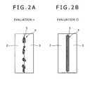
- the stability of the bead was evaluated by observation of a shape of the bead of each of the bonded joints as obtained, rating the case of the bead being discontinuous as defective (X), and the case of the bead being continuous with a substantially constant width as good ( ⁇ ) (refer to Fig. 2 ).
- the evaluation on the joint strength was made by sampling a joint-strength-evaluation test piece 30 mm in sheet width from the respective bonded joints to conduct a tensile test at velocity of 25 mm / min, thereby using shear tensile strength worked out by the following expression (1).
- joint strength ( load at a maximum load point ) / sectional area of a joint where "sectional area of a joint" is a sectional area an aluminum alloy sheet, in the thickness-wise direction thereof.
- the AC - MIG welding, or the MIG welding by DC reversed polarity, relatively low in working current, as a welding method employed in joining dissimilar materials together, among the arc welding, is selected, and the dissimilar materials are joined together by use of each of those welding, singly, or by use of combination thereof.
- the MIG welding by the DC reversed polarity capable of stabilizing an arc with ease, is effective in the case of the need for ensuring bead stability, particularly in the case of, for example, bimetallic joining of a hot-dip galvanized steel sheet.
- occurrence of blowholes in a molten metal zone, due to destabilization of an arc will pose a problem in particular. If the MIG welding by the DC reversed polarity is adopted to cope with this problem, the arc will be stabilized, rendering it easier to obtain a stable bead.
- the input heat value can be controlled, so that the AC - MIG welding has the advantage of checking generation of brittle intermetallic compounds.
- the MIG welding by DC reversed polarity there is a possibility that an input heat value is prone to increase even under the same current condition as that for the AC - MIG welding, resulting in an increase in generation of brittle intermetallic compounds. For this reason, in the case of the MIG welding by DC reversed polarity, it is necessary to execute welding by increasing a welding speed as much as possible, thereby reducing the input heat value.
- melt welding methods other than the respective MIG welding described as above such as the TIG welding method, various melt welding methods using plasma, electron beam, high-frequency wave, and so forth
- a working welding current is excessively high, and an input heat value is excessively high as compared with the respective MIG welding described as above.
- the fluoride-based mixed flux itself becomes prone to scatter during welding, thereby impairing welding workability.
- the spot welding, and so forth are unsuitable for line welding, such as fillet welding, butt welding, and so forth, required of bimetallic joining for the structural members of the automobile, as the object of the invention.
- a welding wire for a welding wire (filler metal)
- a wire with a flux incorporated therein formed by coating a mixed flux containing potassium fluoride, and aluminum fluoride, described in the present description later on, with an aluminum alloy.
- Fig. 3 shows a cross-section of the wire 1 with the flux incorporated therein, for use in the invention.
- the wire 1 with the flux incorporated therein for use in the invention, use can be made of a common wire formed by filling up the interior of a tubular envelope 7 (also called a hoop) of an aluminum material with a flux 6.
- the wire with the flux incorporated therein is also referred to as a flux cored wire (FCW).
- FCW flux cored wire
- the flux cored wire includes a seamed type having a seam (line of juncture: crevice, opening), and a seamless type without a seam, fabricated by sealing the seam by welding, and so forth.
- a seamed type having a seam line of juncture: crevice, opening
- a seamless type without a seam fabricated by sealing the seam by welding, and so forth.
- the flux cored wire having a seam for general use, is preferable.
- the aluminum alloy to be used in the envelope of the flux cored wire use can be made of 4000 series aluminum alloy including A4043, A4047, and so forth, and 5000 series aluminum alloy including A5356, A5183, and so forth.
- use may be made of aluminum alloy including 3000 series, 6000 series, and so forth.
- the flux cored wire (FCW) having the seam can be manufactured by a common manufacturing method. More specifically, the manufacturing method comprises the steps of forming an aluminum alloy sheet or band into a shape resembling the letter U, filling up a formed sheet or band in the shape resembling the letter U with a flux, forming a U-shaped sheet or band into a tubular wire, and so forth. After a formed wire tubular in shape, with the flux filled therein, is manufactured, as above, and the common manufacturing method further comprises the step of drawing the formed wire tubular in shape to a product FCW (flux cored wire) of a fine diameter in a range of 0.8 to 2.4 mm ⁇ .
- FCW flux cored wire
- the diameter of the flux cored wire finer it is preferable to render the diameter of the flux cored wire finer than that in the case of the common manufacturing method, or to use the flux cored wire finer in diameter.
- the input heat value is lowered, and a lower current condition is created upon carrying out the AC - MIG welding, and the MIG welding by the DC reversed polarity.
- the scattering of the fluoride-based mixed flux itself can be prevented, and the welding workability can be improved.
- formation of the brittle intermetallic compounds can be checked. For this reason, use is preferably made of the flux cored wire not more than 1.6 mm ⁇ in diameter.
- the diameter of the flux cored wire is more preferably not more than 1.4 mm.
- the composition of the flux used (filled up) in the flux cored wire is that of the mixed flux (referred to also as the NOKOLOCK (registered trademark) flux ⁇ of a specified composition, mixed with two-fluoride based fluxes, comprising aluminum fluoride, and potassium fluoride, in particular, among fluoride-based fluxes.
- NOKOLOCK registered trademark
- the AC - MIG welding, and the MIG welding by the DC reversed polarity are carried out under suitable conditions described hereunder by use of the flux cored wire of the composition according to the invention, this will make it possible to obtain a suitable thickness of the interfacial reaction layer (IMC: intermetallic compound), thereby improving the joint strength.
- IMC interfacial reaction layer
- a common arc welding is applied to bimetallic joining, an intermetallic compound in excess of 20 ⁇ m in thickness will occur to a weld-interface, bringing about deterioration in the joint strength.
- the interfacial reaction layer will be formed to a suitable thickness not more than 10 ⁇ m, so that the joint strength will be significantly improved.
- the respective MIG welding methods described as above are carried out under suitable conditions described hereunder by use of a solid wire made of an aluminum alloy instead of the flux cored wire of the composition according to the invention, an intermetallic compound in excess of 20 ⁇ m in thickness occurs to the weld-interface, bringing about deterioration in the joint strength.
- the flux of the composition according to the invention, or the flux cored wire of the composition according to the invention has a large effect of checking generation of the intermetallic compound although detained mechanism thereof is still unknown.
- fluoride-based mixed fluxes include, for example, cesium fluoride, zinc fluoride, and so forth, for use in the case of the conventional technology previously described as well. Even those other fluoride-based mixed fluxes each have a function of cleaning up a material surface to an extent.
- cesium fluoride, zinc fluoride, and so forth are extremely high in hygroscopicity. Accordingly, there is concern about possibility of deterioration in corrosion resistance of a weld metal zone besides a tendency of moisture absorbed causing blowholes to be prone to occur to the weld metal.
- advantageous effects of cleaning up the material surface, and enhancing the wettability of the weld metal will become less.
- the melting point of the mixed flux ⁇ NOKOLOCK (registered trademark) flux ⁇ is preferably adjusted to a melting point falling in a range of 560 to 700°C in order that the respective effects described in the foregoing can be exhibited although dependent on the welding conditions by the AC - MIG welding, and the MIG welding by DC reversed polarity, for the bimetallic joining including the hot-dip galvanized steel member.
- the melting point of the mixed flux can be appropriately adjusted by respective mixed amounts (a mixing ratio) of aluminum fluoride (AlF 3 ) powders, and potassium fluoride (KF) powders, and is adjusted according to the welding conditions by the AC - MIG welding, and the MIG welding by DC reversed polarity, for the bimetallic joining including the hot-dip galvanized steel member.
- a ratio of aluminum fluoride on the order of 60 mol % is decided as the upper limit on the basis of eutectic composition of potassium fluoride and potassium fluoride (KF: 55 mol %, AlF 3 : 45 mol %).
- a remaining ratio (the remainder) is assigned to potassium fluoride, and both the fluorides are mixed with each other, whereupon the melting point of the mixed flux is adjusted so as to fall in a melting point range of 560 to 700°C.
- the flux melts in this melting point range (temperature region) so that molten aluminum neatly enters overlapped portions of the steel member and the aluminum member, thereby exhibiting a glue-like effect, and improving a bonding strength.
- a glue-like effect Such an effect as described will be found pronounced particularly with the hot-dip galvanized steel member. If the melting point of the mixed flux is below 560°C, this effect will be less. On the other hand, if the melting point of the mixed flux exceeds 700°C, weld metal at the outset of the welding will spread less, so that influx to the overlapped portions of a joint will become insufficient.
- the loading weight of the NOKOLOCK (registered trademark) flux (the mixed flux) is set relatively small to fall in a range of 0.1 to 24 mass %, against the total mass of the flux cored wire.
- the upper limit of the filling factor of the NOKOLOCK (registered trademark) flux into the flux cored wire is set to a level lower than that for the case of the commercially available conventional flux cored wire for general use, that is, less than 24 mass %. If the filling factor of the flux is 24 mass %, or higher, the filling factor of the flux is excessively high, so that scattering of the molten flux becomes excessive, and the bead is excessively spread, thereby preventing the sound bead from being formed, as described in the foregoing.
- the lower limit of the filling factor of the NOKOLOCK (registered trademark) flux is set to 0.1 %. If the filling factor of the NOKOLOCK (registered trademark) flux is too low, the filling factor becomes the same as that of an aluminum welding wire (JIS specification: A4043 - WY, A4047 - WY, A5356 - WY, A5183 - WY, and so forth) for forming a bead for general use in the arc welding.
- an aluminum welding wire JIS specification: A4043 - WY, A4047 - WY, A5356 - WY, A5183 - WY, and so forth
- the filling factor of the NOKOLOCK (registered trademark) flux is less than 0.1 %, advantageous effects of the NOKOLOCK (registered trademark) flux, such as the effects of enhancement in the wettability, and so forth, cannot be exhibited, so that it is not possible to obtain a sound and highly reliable welded joint.
- the method for joining the dissimilar materials together has fewer constraints in application conditions, and so forth, and is excellent in general versatility while being under fewer constraints in geometrics upon joining an aluminum member with a steel member including the hot-dip galvanized steel member.
- the invention can provides a joining technology whereby continuous joining necessary at the time of the line welding is enabled, generation of the brittle intermetallic compound at the joint, occurrence of blowholes in the weld zone, and deterioration in corrosion resistance are reduced, and welding workability is rendered excellent. Accordingly, it becomes possible to provide a bonded joint of dissimilar materials (welded joint of dissimilar materials) applicable to structural members of the automobile, and so forth.
- FIG. 1 shows one mode of the application.
- an end 2a of an aluminum member 2 is overlaid on an end 3a of a hot-dip galvanized steel member (or a bare steel member) 3 to thereby form an overlapped joint for joining the respective ends 3a, 2a with each other.
- a welding torch 10 and the flux cored wire 1 according the invention are used, and the welding torch 10 is moved along a weld line 5 extending along the respective ends 3a, 2a of the steel member 3, and the aluminum member 2 (in the back-and-forth direction in the figure), thereby applying the respective MIG welding methods described as above to the full length of the weld line 5.
- a tilt angle ⁇ of the welding torch 10 is selected as appropriate.
- reference numeral 4 denotes a weld metal (bead) formed on the weld line 5.
- the method for joining the dissimilar materials together since the steel member can be directly joined with the aluminum member, the method will not be subjected to particular constraints provided that proper welding current, voltage condition, joint shape, and so forth are adopted, having advantageous effects of continuous joining being enabled, together with expansion in an applicable range, and enhancement in general versatility. Further, it is possible to obtain a sound boned state with a necessary minimum melt (diluted) weight of the steel member, in the weld metal such as the bead and so forth, as previously described, and even in the case of the hot-dip galvanized steel member, the brittle intermetallic compound is hard to be formed, so that a high bonding strength can be obtained.
- a necessary minimum melt (diluted) weight of the steel member in the weld metal such as the bead and so forth, as previously described, and even in the case of the hot-dip galvanized steel member, the brittle intermetallic compound is hard to be formed, so that a high bonding strength can be obtained.
- welding is preferably applied such that a sound boned state can be obtained with a necessary minimum melt (diluted) weight of a base metal without causing excessive melt of the steel member, as the base metal, in order to check generation of the brittle intermetallic compound otherwise generated at an interface between the aluminum member, and the steel member.
- the larger amperage of a welding current the more prone to scatter is the flux, so that the brittle intermetallic compound generated on a bond-interface will increase. For this reason, it is recommendable to execute joining on a low current condition from the viewpoint of checking such scattering of the flux, and generation of the brittle intermetallic compound.
- the welding current as recommended is not less than 20A, more preferably not less than 30A, and not more than 100A, more preferably, not more than 80A.
- a welding voltage it is recommendable to execute joining on a low voltage condition in the cases of both the AC - MIG welding, and the MIG welding by DC reversed polarity, as with the case of the welding current.
- the welding voltage recommendable is not lower than 5V, more preferably not lower than 7V, and not higher than 20V, more preferably not higher than 18V.
- a welding speed may be decided as appropriate within a range where Fe and Al in the base metal are not caused to undergo excessive melting, according to the welding current, and the welding voltage.
- the welding speed in the case of the AC - MIG welding is preferably not less than 15 cm / min, more preferably not less than 20 cm / min, and is preferably not more than 60 cm / min, more preferably not more than 50 cm / min.
- the welding speed is preferably not less than 30 cm / min, more preferably not less than 50 cm / min, and is preferably not more than 200 cm / min, more preferably not more than 150 cm / min.
- a gas for general use such as Ar, and so forth, can be used as appropriate, and a flow rate of the shield gas can be selected in a flow rate rage, for general use, for example, from 10 to 50 L / min, and there is no particular limitation thereto.
- a welding torch an arc torch
- the angle ⁇ is selected as appropriate according to the relevant welding, welding conditions of a joint, and so forth.
- construction members to be joined with each other such as automobile members, and large sized panels, made up of the hot-dip galvanized steel member, to be joined with reinforcing members made up of the aluminum alloy member, as previously described.
- bonding such as respective joints of a side member made up of a rectangular hollow section formed from the hot-dip galvanized steel sheet, and a bumper reinforcing member, or a bumper stay, made up of an aluminum alloy extruded hollow section, obtained by directly overlapping respective ends thereof, with each other, as shown in Fig. 1 , or obtained by overlapping respective flange faces provided at the respective ends thereof.
- a zinc (including alloying zinc) hot-dip galvanized steel member that has been difficult by nature for use in bimetallic joining can be used in the invention.
- a galvanized steel member including hot dip galvanizing, an arc becomes unstable by the agency of zinc vapor as evolved, thereby causing problems of generation of spatters, and occurrence of porous defects such as pits, blowholes, and so forth.
- the steel member (iron based material) itself used in the invention is a steel member such as mild steel, high tensile steel (Hi-Ten), and so forth.
- a steel member such as mild steel, high tensile steel (Hi-Ten), and so forth.
- type and shape of the steel member used in the invention and use can be made of a steel member appropriate in shape and material type, such as a steel sheet, steel section, steel pipe, and so forth, for general use as a structural member, or diverted from application for the structural member.
- use of the high tensile steel (Hi-Ten) is preferable.
- An aluminum member for use in the invention has no particular limitation to type and shape of an alloy thereof, and selection, as appropriate, is made of a rolled sheet member, shaped member such as an extrusion, forged member, cast member, and so forth, for general use according to properties required of respective structural members.
- use is preferably made of aluminum alloy of an Al-Mg base, Al-Mg-Si base, or Al-Mg-Zn base for general use as aluminum alloy capable of meeting requirements for various properties such as formability, and so forth, or aluminum alloy of 5000 series, 6000 series, 7000 series, according to JIS or AAA specification, and so forth. Selection as appropriate is made out of those aluminum alloys after tempering treatment is applied thereto according to strength required by the structural member, and formability.
- the MIG welding of the aluminum alloy sheet with the galvanized steel sheet was conducted by use of a flux cored wire with a mixed flux composed of AlF 3 and KF, the filling factor of the flux being variously changed.
- a mixing ratio of KF to AlF 3 , in the flux was kept constant for both the working examples and the comparative examples such that the melting point of the flux remained constant at 650°C, using the flux composed of a mixture of KF: 45 mol %, and AlF 3 : 55 mol %.
- use was made of the flux cored wire 1.2 mm ⁇ in diameter.
- For an aluminum envelope of the flux cored wire use was made of the A4043 type, and in the step of the drawing described previously, the flux cored wire was formed to the final diameter at 1.2 mm ⁇ as above.
- the AC - MIG welding was applied under the same condition as in the case of the working examples to respective examples where use was made of a flux cored wire obtained by substituting cesium fluoride, and zinc fluoride, used in the past, for part of KF, a flux containing 10 mol % each of cesium fluoride, and zinc fluoride, together with a mixture of KF: 45 mol % , and AlF 3 : 55 mol %.
- Those are shown as comparative examples 8, 9 in Table 5.
- the filling factor of the flux of each of the comparative examples 8, 9 was 10 mass %, the same as that for the working examples. Further, the comparative examples 8, 9 each had a melting point around 500°C.
- a test piece was sampled from respective bonded joints, and various tests were conducted on the respective test pieces, whereupon respective test results were averaged out to be used for evaluations.
- shear tensile strength a joint-strength-evaluation test piece 30 mm in sheet width was sampled from the respective joints bonded three times, and a tensile test at velocity of 25 mm / min was conducted on the respective test pieces, thereby having found an average value of the shear tensile strength for the respective examples.
- a spread width (a) of the weld metal 4, and a height (b) of the weld metal 4 were measured at appropriate intervals along the weld line, respectively, as shown in Fig. 4 corresponding to Fig. 1 , in schematic form. Thereafter, a ratio of "a" to "b", a / b, was averaged out along the weld line, and with the respective samples, the average a / b for each of 3 test pieces (as obtained from 3 welding tests) was further averaged out.
- weight of fume evolved during welding As for the welding workability, evaluation was made on weight of fume evolved during welding, and bead stability.
- the weight of the fume evolved was measured according to JIS - Z3930. More specifically, total fume evolved at the time of the welding using the respective flux cored wires was collected to thereby find the weight of the fume evolved per unit time. With the respective example, the weights of the fume evolved, obtained from the three welding tests, respectively, were averaged out. If the weight of the fume evolved, on average, was less than 300 mg / min, it was rated 0, if the same is in a range of 300 to 700 mg / min, it was rated ⁇ , and if the same is not less than 700 mg / min, it was rated X.
- the bead stability was evaluated according to the criteria based on a bead shape formed, as shown in Fig. 2 .
- the case where a bead was linearly, and neatly formed as shown in Fig. 2 (b) with all the three welding tests was rated ⁇ while the case where a bead was formed only discontinuously even during only one of the welding tests was rated X.
- Those results are shown in Tables 5 and 6, respectively.
- the invention can provide a flux cored wire for joining dissimilar materials with each other, capable of enhancing a bonding strength in melt weld-bonding of high-strength dissimilar materials with each other, that is, the high-strength steel member with the high-strength 6000 series aluminum alloy member, and excellent in welding efficiency, and a method for joining the dissimilar materials with each other.
- a bonded joint of dissimilar materials such as a galvanized steel member and an aluminum member, without any constraint on shapes of base metals to be joined together, without causing generation of a brittle intermetallic compound at the bonded joint, excellent in external appearance, and without causing occurrence of defects such as blowholes, and so forth if joining is executed by the AC - MIG welding using the flux cored wire according to the invention, wherein a flux filling factor, and a melting point are properly controlled.
- the aggregate of the dissimilar materials joined obtained as above, is superior in bonding strength, and welding efficiency, the aggregate can be quite usefully applied to various structural members of automobiles, railway vehicles, and so forth, in the transportation field, machine components, construction members such as building structures, and so forth.
- the invention will greatly contribute to expansion of application for the aggregate of the dissimilar materials, for example, a steel member and an aluminum member, joined together, high in strength.
Landscapes
- Engineering & Computer Science (AREA)
- Mechanical Engineering (AREA)
- Physics & Mathematics (AREA)
- Plasma & Fusion (AREA)
- Chemical & Material Sciences (AREA)
- Materials Engineering (AREA)
- Nonmetallic Welding Materials (AREA)
- Arc Welding In General (AREA)
Applications Claiming Priority (5)
| Application Number | Priority Date | Filing Date | Title |
|---|---|---|---|
| JP2006041135A JP4256879B2 (ja) | 2006-02-17 | 2006-02-17 | 鉄系材料とアルミニウム系材料との接合方法および接合継手 |
| JP2006107491 | 2006-04-10 | ||
| JP2006249679A JP4256886B2 (ja) | 2006-09-14 | 2006-09-14 | 異材接合用フラックスコアードワイヤおよび異材接合方法 |
| JP2006310535A JP4256892B2 (ja) | 2006-04-10 | 2006-11-16 | 異材接合方法 |
| PCT/JP2007/052041 WO2007094203A1 (ja) | 2006-02-17 | 2007-02-06 | 異材接合用フラックスコアードワイヤおよび異材接合方法 |
Publications (3)
| Publication Number | Publication Date |
|---|---|
| EP1997579A1 true EP1997579A1 (de) | 2008-12-03 |
| EP1997579A4 EP1997579A4 (de) | 2010-05-26 |
| EP1997579B1 EP1997579B1 (de) | 2013-12-25 |
Family
ID=38371389
Family Applications (1)
| Application Number | Title | Priority Date | Filing Date |
|---|---|---|---|
| EP07713870.9A Not-in-force EP1997579B1 (de) | 2006-02-17 | 2007-02-06 | Fülldraht für das verbinden von verschiedenen materialien und verfahren zum verbinden verschiedener materialien |
Country Status (4)
| Country | Link |
|---|---|
| US (2) | US9682446B2 (de) |
| EP (1) | EP1997579B1 (de) |
| KR (1) | KR101021397B1 (de) |
| WO (1) | WO2007094203A1 (de) |
Cited By (6)
| Publication number | Priority date | Publication date | Assignee | Title |
|---|---|---|---|---|
| EP2281657A1 (de) * | 2008-04-21 | 2011-02-09 | Honda Motor Co., Ltd. | Verbindungsverfahren für metallelemente und verbundene struktur daraus sowie lötfüllmaterial |
| FR2984785A1 (fr) * | 2011-12-21 | 2013-06-28 | Kobe Steel Ltd | Fil fourre permettant de souder des materiaux differents, procede de soudage au laser de materiaux differents et procede de soudage mig de materiaux differents |
| FR2996479A1 (fr) * | 2012-10-09 | 2014-04-11 | Peugeot Citroen Automobiles Sa | Procede d’assemblage de toles en materiaux differents |
| DE102011115654B4 (de) * | 2010-09-29 | 2014-09-11 | Kabushiki Kaisha Kobe Seiko Sho (Kobe Steel, Ltd.) | Draht mit Flussmittelkern zum Schweißen von verschiedenartigen Materialien, Verfahren zum Laserschweißen von verschiedenartigen Materialien und Verfahren zum MIG-Schweißen von verschiedenartigen Materialien |
| US9186754B2 (en) | 2009-07-31 | 2015-11-17 | Kobe Steel, Ltd. | Flux-cored wire for welding different materials, method for laser welding of different materials, and method for MIG welding of different materials |
| CN105479036A (zh) * | 2016-01-04 | 2016-04-13 | 威县亚泰密封件有限公司 | 一种金属颗粒增强型药芯焊丝及其制备方法 |
Families Citing this family (64)
| Publication number | Priority date | Publication date | Assignee | Title |
|---|---|---|---|---|
| JP5572046B2 (ja) * | 2010-09-13 | 2014-08-13 | 株式会社神戸製鋼所 | 異材接合方法 |
| US20120181255A1 (en) * | 2011-01-13 | 2012-07-19 | Bruck Gerald J | Flux enhanced high energy density welding |
| JP5410466B2 (ja) * | 2011-03-01 | 2014-02-05 | 株式会社神戸製鋼所 | ステンレス鋼フラックス入りワイヤ |
| KR101223906B1 (ko) * | 2011-03-04 | 2013-01-17 | 한국기계연구원 | 적외선 가열을 이용한 고강도 알루미늄합금 클래드판의 제조방법 및 이에 따라 제조되는 알루미늄합금 클래드판 |
| CN105149750B (zh) * | 2011-03-07 | 2017-05-03 | 株式会社神户制钢所 | 异种金属接合方法 |
| CA2830543C (en) * | 2011-03-23 | 2017-07-25 | Scoperta, Inc. | Fine grained ni-based alloys for resistance to stress corrosion cracking and methods for their design |
| US11504814B2 (en) | 2011-04-25 | 2022-11-22 | Holtec International | Air cooled condenser and related methods |
| WO2013109968A1 (en) * | 2012-01-18 | 2013-07-25 | Holtec International, Inc. | Finned tube assemblies for heat exchangers |
| WO2014089072A2 (en) | 2012-12-03 | 2014-06-12 | Holtec International, Inc. | Brazing compositions and uses thereof |
| CN102179640B (zh) * | 2011-04-26 | 2013-03-13 | 武汉铁锚焊接材料股份有限公司 | 一种高强度高韧性金属粉芯型药芯焊丝 |
| CN102441747B (zh) * | 2011-06-28 | 2012-12-26 | 力创(台山)电子科技有限公司 | 一种用于焊接铝及铝合金药芯焊丝的钎剂 |
| JP2013043206A (ja) * | 2011-08-24 | 2013-03-04 | Kobe Steel Ltd | フラックス組成物及びブレージングシート |
| FR2980382B1 (fr) * | 2011-09-27 | 2013-10-11 | Snecma | Procede de soudage et de rechargement de pieces metalliques en aluminium par un procede mig avec courant et fil d'apport pulses |
| US9180553B2 (en) * | 2011-09-29 | 2015-11-10 | Lincoln Global, Inc. | Electrode for GMAW hybrid laser arc welding |
| AU2012362827B2 (en) | 2011-12-30 | 2016-12-22 | Scoperta, Inc. | Coating compositions |
| US9029733B2 (en) * | 2012-04-13 | 2015-05-12 | Hobart Brothers Company | Systems and methods for tubular welding wire |
| CN102658439A (zh) * | 2012-05-15 | 2012-09-12 | 力创(台山)电子科技有限公司 | 用于焊接铝或铝合金产品的钎焊铝焊环及制备方法 |
| US8740041B2 (en) | 2012-07-03 | 2014-06-03 | Flux Brazing Schweiss-Und Lotstoffe Usa, Llc | Extruded brazing ring with integrated flux |
| US10016850B2 (en) | 2012-08-28 | 2018-07-10 | Hobart Brothers Company | Systems and methods for welding electrodes |
| US10543556B2 (en) | 2012-08-28 | 2020-01-28 | Hobart Brothers Llc | Systems and methods for welding zinc-coated workpieces |
| US9999944B2 (en) | 2012-08-28 | 2018-06-19 | Hobart Brothers Company | Systems and methods for welding electrodes |
| CA2887726A1 (en) | 2012-10-11 | 2014-04-17 | Scoperta, Inc. | Non-magnetic metal alloy compositions and applications |
| CN102935559B (zh) * | 2012-12-04 | 2015-03-04 | 郑州机械研究所 | 含有铍镁和铷盐的复合药芯锌铝焊丝的制造方法 |
| US9878399B2 (en) * | 2013-03-15 | 2018-01-30 | Jian Liu | Method and apparatus for welding dissimilar material with a high energy high power ultrafast laser |
| JP5667654B2 (ja) * | 2013-04-10 | 2015-02-12 | 本田技研工業株式会社 | アーク溶接方法及びアーク溶接装置 |
| JP5989596B2 (ja) * | 2013-04-25 | 2016-09-07 | 株式会社神戸製鋼所 | フラックス組成物及びブレージングシート |
| US10124437B2 (en) * | 2013-08-19 | 2018-11-13 | Covidien Lp | Laser welding of nickel titanium alloys |
| US10112268B2 (en) | 2013-10-09 | 2018-10-30 | Hobart Brothers Company | Systems and methods for corrosion-resistant welding electrodes |
| CN109830269B (zh) | 2013-10-10 | 2023-09-19 | 思高博塔公司 | 选择材料组合物和设计具有目标特性的材料的方法 |
| CA2931842A1 (en) | 2013-11-26 | 2015-06-04 | Scoperta, Inc. | Corrosion resistant hardfacing alloy |
| JP5847209B2 (ja) * | 2014-01-21 | 2016-01-20 | 株式会社神戸製鋼所 | 異種金属接合体及び異種金属接合体の製造方法 |
| WO2015118391A1 (en) * | 2014-02-04 | 2015-08-13 | Sares S.P.A. | Device of electric sliding contact, welding head for roller welding machines and related roller welding machine |
| EP2942143B1 (de) | 2014-05-09 | 2017-03-15 | Gestamp HardTech AB | Verfahren zum Verbinden von zwei Rohlingen sowie Rohlinge und erhaltenes Produkte |
| CN106661702B (zh) | 2014-06-09 | 2019-06-04 | 斯克皮尔塔公司 | 抗开裂硬面堆焊合金 |
| MY190226A (en) | 2014-07-24 | 2022-04-06 | Oerlikon Metco Us Inc | Hardfacing alloys resistant to hot tearing and cracking |
| WO2016014665A1 (en) | 2014-07-24 | 2016-01-28 | Scoperta, Inc. | Impact resistant hardfacing and alloys and methods for making the same |
| US10300565B2 (en) | 2014-10-17 | 2019-05-28 | Hobart Brothers Company | Systems and methods for welding mill scaled workpieces |
| JP6257508B2 (ja) * | 2014-12-12 | 2018-01-10 | 株式会社神戸製鋼所 | フラックス入りワイヤ及び溶接継手の製造方法 |
| CN107532265B (zh) | 2014-12-16 | 2020-04-21 | 思高博塔公司 | 含多种硬质相的韧性和耐磨铁合金 |
| JP6558920B2 (ja) * | 2015-01-26 | 2019-08-14 | 株式会社神戸製鋼所 | 溶接装置及び溶接方法 |
| US20160297026A1 (en) * | 2015-04-13 | 2016-10-13 | Lincoln Global, Inc. | Engine driven welder with lever for polarity and output range |
| JP6114785B2 (ja) | 2015-05-29 | 2017-04-12 | 日新製鋼株式会社 | 溶接部外観と溶接強度に優れた溶融Zn系めっき鋼板のアーク溶接方法、および溶接部材の製造方法 |
| CA2997367C (en) | 2015-09-04 | 2023-10-03 | Scoperta, Inc. | Chromium free and low-chromium wear resistant alloys |
| CN107949653B (zh) | 2015-09-08 | 2021-04-13 | 思高博塔公司 | 用于粉末制造的形成非磁性强碳化物的合金 |
| CA3003048C (en) | 2015-11-10 | 2023-01-03 | Scoperta, Inc. | Oxidation controlled twin wire arc spray materials |
| CA2943252C (en) * | 2015-12-04 | 2019-01-29 | Hobart Brothers Company | Systems and methods for welding zinc-coated workpieces |
| US11279996B2 (en) | 2016-03-22 | 2022-03-22 | Oerlikon Metco (Us) Inc. | Fully readable thermal spray coating |
| US11339817B2 (en) | 2016-08-04 | 2022-05-24 | Honda Motor Co., Ltd. | Multi-material component and methods of making thereof |
| US11318566B2 (en) | 2016-08-04 | 2022-05-03 | Honda Motor Co., Ltd. | Multi-material component and methods of making thereof |
| US10640854B2 (en) | 2016-08-04 | 2020-05-05 | Honda Motor Co., Ltd. | Multi-material component and methods of making thereof |
| KR20190078660A (ko) * | 2017-01-11 | 2019-07-04 | 아르코닉 인코포레이티드 | 접합용 알루미늄 합금 제품 제조 방법 |
| EP3587614B8 (de) | 2017-02-22 | 2021-01-20 | Nippon Steel Corporation | Laserlötverfahren und herstellungsverfahren für überlappungsverbindungselement |
| CN110312587B (zh) | 2017-02-22 | 2021-02-26 | 日铁日新制钢株式会社 | Mig钎焊方法、搭接接头构件的制造方法及搭接接头构件 |
| JP6936863B2 (ja) | 2017-03-06 | 2021-09-22 | アーコニック テクノロジーズ エルエルシーArconic Technologies Llc | 接着接合用の7xxxアルミニウム合金の調製方法、およびそれに関連する製品 |
| US20200164472A1 (en) * | 2017-08-02 | 2020-05-28 | Nippon Welding Rod Co., Ltd. | Wire for welding different types of materials and method of manufacturing the same |
| KR102529451B1 (ko) * | 2018-07-10 | 2023-05-08 | 현대자동차주식회사 | 알루미늄-스틸 브레이징을 위한 필러와이어 |
| WO2020086971A1 (en) | 2018-10-26 | 2020-04-30 | Oerlikon Metco (Us) Inc. | Corrosion and wear resistant nickel based alloys |
| EP3957428B1 (de) * | 2019-04-19 | 2024-01-10 | Panasonic Intellectual Property Management Co., Ltd. | Verbindungsstruktur und verbindungsverfahren |
| WO2020227099A1 (en) | 2019-05-03 | 2020-11-12 | Oerlikon Metco (Us) Inc. | Powder feedstock for wear resistant bulk welding configured to optimize manufacturability |
| CA3165854A1 (en) * | 2019-12-25 | 2021-07-01 | Nippon Light Metal Company, Ltd. | Joining method |
| US11511375B2 (en) | 2020-02-24 | 2022-11-29 | Honda Motor Co., Ltd. | Multi component solid solution high-entropy alloys |
| KR20230115730A (ko) * | 2022-01-27 | 2023-08-03 | 현대자동차주식회사 | 이종 소재의 아크 브레이징 접합 방법 및 자동차용 부품 |
| CN115194278B (zh) * | 2022-08-11 | 2023-10-27 | 中车青岛四方机车车辆股份有限公司 | 密封钎焊方法及钎焊系统 |
| CN116021190B (zh) * | 2023-02-23 | 2024-09-10 | 江苏东南焊材有限公司 | 一个铝基药芯焊丝 |
Citations (4)
| Publication number | Priority date | Publication date | Assignee | Title |
|---|---|---|---|---|
| JPH09155548A (ja) * | 1995-12-05 | 1997-06-17 | Showa Alum Corp | 金属材の溶接方法 |
| JPH1034377A (ja) * | 1996-07-18 | 1998-02-10 | Showa Alum Corp | アルミニウム材料と鉄系材料との接合部材の製造方法 |
| JP2003048077A (ja) * | 2001-07-31 | 2003-02-18 | Kobe Steel Ltd | AlまたはAl合金部材の接合法 |
| JP2003211270A (ja) * | 2002-01-18 | 2003-07-29 | Daihen Corp | アルミニウムと鉄鋼の接合方法 |
Family Cites Families (76)
| Publication number | Priority date | Publication date | Assignee | Title |
|---|---|---|---|---|
| US2470763A (en) * | 1946-09-13 | 1949-05-24 | Doyle Dorris Monell | Flux coated aluminum rod for gas welding |
| US3393102A (en) * | 1965-01-15 | 1968-07-16 | Lincoln Electric Co | Arc welding flux |
| US3340104A (en) * | 1965-04-29 | 1967-09-05 | Gen Dynamics Corp | Welding flux |
| JPS516096B1 (de) * | 1967-01-23 | 1976-02-25 | ||
| US3911244A (en) * | 1969-09-13 | 1975-10-07 | Ishikawajima Harima Heavy Ind | Electrode composition and welding method for arc welding steel |
| US3924091A (en) * | 1970-08-12 | 1975-12-02 | Nippon Steel Corp | Welding method and materials |
| JPS5017304B1 (de) * | 1971-03-02 | 1975-06-19 | ||
| US3935421A (en) * | 1972-05-04 | 1976-01-27 | Unicore, Inc. | Flux-cored welding wire for gas-shielded electric arc welding |
| US3951328A (en) * | 1972-08-02 | 1976-04-20 | Alcan Research And Development Limited | Joining of metal surfaces |
| DE2364893C3 (de) * | 1972-12-29 | 1979-12-06 | Nippon Steel Corp., Tokio | Seelenelektrode zum automatischen oder halbautomatischen Lichtbogenschweißen von Stahl |
| US3941588A (en) * | 1974-02-11 | 1976-03-02 | Foote Mineral Company | Compositions for alloying metal |
| US3935414A (en) * | 1974-10-11 | 1976-01-27 | Unicore, Inc. | Automatic fixed position pipe welding |
| US3971501A (en) * | 1975-04-09 | 1976-07-27 | Alcan Research And Development Limited | Method of brazing aluminum |
| US4133935A (en) * | 1977-11-17 | 1979-01-09 | The United States Of America As Represented By The Secretary Of The Navy | Coated electrodes for underwater metal working |
| DE2936364C2 (de) * | 1979-09-08 | 1982-06-03 | Messer Griesheim Gmbh, 6000 Frankfurt | Schweißpulver zum Unterpulverschweißen von Leichtmetallen wie Aluminium-Legierungen |
| JPS5944156B2 (ja) * | 1981-07-27 | 1984-10-26 | 株式会社神戸製鋼所 | 肉盛溶接用フラツクス |
| JPS58167097A (ja) * | 1982-03-29 | 1983-10-03 | Nikkei Giken:Kk | ろう付用フラツクス |
| CA1235048A (en) * | 1983-05-23 | 1988-04-12 | Yoji Awano | Method for producing aluminum alloy castings and the resulting product |
| US4619716A (en) * | 1983-10-13 | 1986-10-28 | Kabushiki Kaisha Toyota Chuo Kenkyusho | Method of brazing an aluminum material |
| JPS60118389A (ja) | 1983-12-01 | 1985-06-25 | Sumitomo Light Metal Ind Ltd | ア−ク溶接によるアルミ・チタン接合方法 |
| JPS61162295A (ja) | 1985-01-11 | 1986-07-22 | Toyota Central Res & Dev Lab Inc | ろう付け用フラツクス |
| JPS62207598A (ja) | 1986-03-06 | 1987-09-11 | Kawasaki Steel Corp | 無被包ア−ク溶接用フラツクスコア−ドワイヤ |
| US4723061A (en) * | 1986-07-31 | 1988-02-02 | The Lincoln Electric Company | Gas shielded, flux cored, welding electrode |
| US4683011A (en) * | 1986-08-28 | 1987-07-28 | The Lincoln Electric Company | High penetration, high speed, agglomerated welding flux |
| US4906307A (en) * | 1987-10-16 | 1990-03-06 | Calsonic Corporation | Flux used for brazing aluminum-based alloy |
| US5100486A (en) * | 1989-04-14 | 1992-03-31 | The United States Of America As Represented By The United States Department Of Energy | Method of coating metal surfaces to form protective metal coating thereon |
| JPH0763866B2 (ja) * | 1989-12-01 | 1995-07-12 | 株式会社豊田中央研究所 | ろう付け用フラックス |
| JPH0669633B2 (ja) * | 1989-12-08 | 1994-09-07 | 株式会社神戸製鋼所 | ガスシールドアーク溶接用フラックス入リワイヤ |
| US5124530A (en) * | 1990-03-22 | 1992-06-23 | Inco Alloys International, Inc. | Stable low fume stainless steel welding electrode |
| JPH058056A (ja) | 1991-06-28 | 1993-01-19 | Kinzoku Giken Kk | ステンレス鋼とアルミニウム又はアルミニウム合金の接合方法 |
| US5547517A (en) * | 1991-12-27 | 1996-08-20 | Showa Aluminum Corporation | Brazing agent and a brazing sheet both comprising an aluminum alloy containing a flux |
| JPH0639558A (ja) | 1992-07-23 | 1994-02-15 | Sumitomo Metal Ind Ltd | アルミニウムと鋼の抵抗溶接方法 |
| JPH0663762A (ja) | 1992-08-11 | 1994-03-08 | Nippon Steel Corp | 異種金属接合用材料 |
| JPH06198458A (ja) | 1992-10-27 | 1994-07-19 | Kinzoku Giken Kk | 異種金属の接合方法 |
| US5781846A (en) * | 1993-02-25 | 1998-07-14 | Jossick; James L. | Flux cored brazing composition |
| JPH06304780A (ja) * | 1993-04-23 | 1994-11-01 | Isuzu Motors Ltd | 溶接用アルミワイヤー |
| US5418072A (en) * | 1993-09-20 | 1995-05-23 | Alcan International Limited | Totally consumable brazing encapsulate for use in joining aluminum surfaces |
| JPH07148571A (ja) | 1993-11-26 | 1995-06-13 | Toyota Motor Corp | 鉄材とアルミニウム材とのろう付方法 |
| JPH07314176A (ja) | 1994-05-27 | 1995-12-05 | Nippon Steel Corp | ガスシールドアーク溶接用シームレスフラックス入りワイヤ |
| US5802716A (en) * | 1994-09-30 | 1998-09-08 | Toyota Jidosha Kabushiki Kaisha | Method for bonding a valve seat with a cylinder head |
| JPH08141755A (ja) | 1994-11-18 | 1996-06-04 | Showa Alum Corp | 異種金属材料の摩擦圧接方法 |
| CA2231870C (en) * | 1995-09-19 | 2005-02-22 | Alcan International Limited | Precipitation-hardened aluminum alloys for automotive structural applications |
| JPH09300097A (ja) * | 1996-05-13 | 1997-11-25 | Kobe Steel Ltd | ステンレス鋼用フラックス入りワイヤ |
| JP3212927B2 (ja) * | 1996-12-14 | 2001-09-25 | 三菱アルミニウム株式会社 | アルミニウム合金粉末ろう材および該粉末ろう材を用いたろう付方法 |
| JPH10185040A (ja) | 1996-12-26 | 1998-07-14 | Mitsubishi Heavy Ind Ltd | 異材継手 |
| JPH10314933A (ja) | 1997-05-15 | 1998-12-02 | Showa Alum Corp | アルミニウム材料と鉄材料の接合方法 |
| FR2764221B1 (fr) * | 1997-06-09 | 1999-07-16 | Soudure Autogene Francaise | Fil fourre basse teneur azote |
| US6339209B1 (en) * | 1997-12-05 | 2002-01-15 | Lincoln Global, Inc. | Electrode and flux for arc welding stainless steel |
| JP3767147B2 (ja) | 1998-01-14 | 2006-04-19 | Jfeスチール株式会社 | 異種金属板のシーム溶接方法 |
| US6203628B1 (en) * | 1998-08-20 | 2001-03-20 | Toyo Aluminium Kabushiki Kaisha | Flux compositions for brazing aluminum, their films and brazing method |
| JP2000094162A (ja) | 1998-09-24 | 2000-04-04 | Mitsubishi Heavy Ind Ltd | 異種金属の真空圧延接合方法 |
| JP2000117484A (ja) * | 1998-10-19 | 2000-04-25 | Senko Kinzoku:Kk | 継目なしリング状ブレージング材及びその製造方法 |
| AU751115B2 (en) * | 1999-04-22 | 2002-08-08 | Corus Aluminium Walzprodukte Gmbh | Composite sheet material for brazing |
| JP3398085B2 (ja) * | 1999-04-28 | 2003-04-21 | 古河電気工業株式会社 | 溶接構造用Al合金材とその溶接継手 |
| US6497770B2 (en) * | 2000-02-17 | 2002-12-24 | Toyo Aluminium Kabushiki Kaisha | Flux-containing compositions for brazing aluminum, films and brazing method thereby |
| JP2001353591A (ja) * | 2000-06-12 | 2001-12-25 | Showa Denko Kk | アルミニウム合金のレーザ溶接給線用フィラーワイヤ、アルミニウム合金の溶接方法およびアルミニウム合金製溶接部材 |
| US6933468B2 (en) * | 2000-10-10 | 2005-08-23 | Hobart Brothers Company | Aluminum metal-core weld wire and method for forming the same |
| JP2003033865A (ja) | 2001-07-23 | 2003-02-04 | Kobe Steel Ltd | アルミニウムまたはアルミニウム合金と鋼材との接合法および接合継手 |
| JP2004210023A (ja) | 2002-12-27 | 2004-07-29 | Showa Denko Kk | 車両用フレーム及び車両 |
| JP2004210013A (ja) | 2002-12-27 | 2004-07-29 | Showa Denko Kk | 車両用中空フレーム及び車両 |
| JP2004223548A (ja) | 2003-01-21 | 2004-08-12 | Daihen Corp | アルミニウムと鉄鋼の接合方法 |
| EP1462207A1 (de) * | 2003-03-29 | 2004-09-29 | Grillo-Werke AG | Verfahren zum Schutzgasschweissen oder Schutzgaslöten von Werkstücken gleicher oder verschiedener Metalle oder Metalllegierungen mit einem Zn/Al Zusatzmaterial |
| JP4398428B2 (ja) * | 2003-04-07 | 2010-01-13 | 社団法人日本航空宇宙工業会 | 耐食性に優れた高強度アルミニウム合金押出材およびその製造方法 |
| JP2004351507A (ja) | 2003-05-30 | 2004-12-16 | Kobe Steel Ltd | 鉄系材料とアルミニウム系材料とのスポット溶接接合方法および接合継手 |
| US7150797B2 (en) * | 2003-06-20 | 2006-12-19 | Nissan Motor Co., Ltd. | Filler material for use in welding of Mg-contained aluminum alloy die-cast members, welding method, and welded article |
| US7850059B2 (en) * | 2004-12-24 | 2010-12-14 | Nissan Motor Co., Ltd. | Dissimilar metal joining method |
| US7491910B2 (en) * | 2005-01-24 | 2009-02-17 | Lincoln Global, Inc. | Hardfacing electrode |
| US20060207984A1 (en) * | 2005-03-17 | 2006-09-21 | Lincoln Global, Inc. | Flux cored electrode |
| US7829820B2 (en) * | 2005-04-05 | 2010-11-09 | Lincoln Global, Inc. | Flux cored electrode with fluorine |
| US7239820B2 (en) * | 2005-05-03 | 2007-07-03 | Xerox Corporation | Tone reproduction curve systems and methods |
| JP5014833B2 (ja) * | 2007-02-27 | 2012-08-29 | 住友軽金属工業株式会社 | アルミニウム材と鋼材のmig溶接方法 |
| JP5014834B2 (ja) * | 2007-02-27 | 2012-08-29 | 住友軽金属工業株式会社 | アルミニウム材と鋼材のmig溶接方法 |
| EP2070638A1 (de) * | 2007-12-11 | 2009-06-17 | Solvay Fluor GmbH | Verfahren zum Löten von Titan- und Aluminiumteilen und dadurch gewonnene Teile |
| JP5520152B2 (ja) * | 2009-07-31 | 2014-06-11 | 株式会社神戸製鋼所 | 異材溶接用フラックス入りワイヤ並びに異材レーザ溶接方法及び異材mig溶接方法 |
| US20150336219A1 (en) * | 2011-01-13 | 2015-11-26 | Siemens Energy, Inc. | Composite materials and methods for laser manufacturing and repair of metals |
| JP5689492B2 (ja) * | 2013-03-19 | 2015-03-25 | 株式会社神戸製鋼所 | 異材接合用溶加材及び異材溶接構造体の製造方法 |
-
2007
- 2007-02-06 KR KR1020087019924A patent/KR101021397B1/ko active IP Right Grant
- 2007-02-06 WO PCT/JP2007/052041 patent/WO2007094203A1/ja active Application Filing
- 2007-02-06 US US12/279,470 patent/US9682446B2/en not_active Expired - Fee Related
- 2007-02-06 EP EP07713870.9A patent/EP1997579B1/de not_active Not-in-force
-
2017
- 2017-04-28 US US15/582,078 patent/US20170274479A1/en not_active Abandoned
Patent Citations (4)
| Publication number | Priority date | Publication date | Assignee | Title |
|---|---|---|---|---|
| JPH09155548A (ja) * | 1995-12-05 | 1997-06-17 | Showa Alum Corp | 金属材の溶接方法 |
| JPH1034377A (ja) * | 1996-07-18 | 1998-02-10 | Showa Alum Corp | アルミニウム材料と鉄系材料との接合部材の製造方法 |
| JP2003048077A (ja) * | 2001-07-31 | 2003-02-18 | Kobe Steel Ltd | AlまたはAl合金部材の接合法 |
| JP2003211270A (ja) * | 2002-01-18 | 2003-07-29 | Daihen Corp | アルミニウムと鉄鋼の接合方法 |
Non-Patent Citations (1)
| Title |
|---|
| See also references of WO2007094203A1 * |
Cited By (12)
| Publication number | Priority date | Publication date | Assignee | Title |
|---|---|---|---|---|
| EP2281657A1 (de) * | 2008-04-21 | 2011-02-09 | Honda Motor Co., Ltd. | Verbindungsverfahren für metallelemente und verbundene struktur daraus sowie lötfüllmaterial |
| EP2281657A4 (de) * | 2008-04-21 | 2011-04-27 | Honda Motor Co Ltd | Verbindungsverfahren für metallelemente und verbundene struktur daraus sowie lötfüllmaterial |
| US8492675B2 (en) | 2008-04-21 | 2013-07-23 | Honda Motor Co., Ltd. | Laser welding Al and Fe members with Zn filler |
| US9186754B2 (en) | 2009-07-31 | 2015-11-17 | Kobe Steel, Ltd. | Flux-cored wire for welding different materials, method for laser welding of different materials, and method for MIG welding of different materials |
| DE102011115654B4 (de) * | 2010-09-29 | 2014-09-11 | Kabushiki Kaisha Kobe Seiko Sho (Kobe Steel, Ltd.) | Draht mit Flussmittelkern zum Schweißen von verschiedenartigen Materialien, Verfahren zum Laserschweißen von verschiedenartigen Materialien und Verfahren zum MIG-Schweißen von verschiedenartigen Materialien |
| US8907246B2 (en) | 2010-09-29 | 2014-12-09 | Kabushiki Kaisha Kobe Seiko Sho | Flux-cored wire for welding different materials, method for laser welding of different materials and method for MIG welding of different materials |
| FR2984785A1 (fr) * | 2011-12-21 | 2013-06-28 | Kobe Steel Ltd | Fil fourre permettant de souder des materiaux differents, procede de soudage au laser de materiaux differents et procede de soudage mig de materiaux differents |
| FR2996479A1 (fr) * | 2012-10-09 | 2014-04-11 | Peugeot Citroen Automobiles Sa | Procede d’assemblage de toles en materiaux differents |
| WO2014057183A1 (fr) * | 2012-10-09 | 2014-04-17 | Peugeot Citroen Automobiles Sa | Procédé d'assemblage par soudage d'une tôle en aluminium ayant une lumière avec une tôle en acier |
| CN104703743A (zh) * | 2012-10-09 | 2015-06-10 | 标致雪铁龙集团 | 通过焊接具有孔口的铝板和钢板的组装方法 |
| CN104703743B (zh) * | 2012-10-09 | 2018-07-03 | 标致雪铁龙集团 | 通过焊接具有孔口的铝板和钢板的组装方法 |
| CN105479036A (zh) * | 2016-01-04 | 2016-04-13 | 威县亚泰密封件有限公司 | 一种金属颗粒增强型药芯焊丝及其制备方法 |
Also Published As
| Publication number | Publication date |
|---|---|
| EP1997579B1 (de) | 2013-12-25 |
| US20090017328A1 (en) | 2009-01-15 |
| KR101021397B1 (ko) | 2011-03-14 |
| US20170274479A1 (en) | 2017-09-28 |
| KR20080087034A (ko) | 2008-09-29 |
| US9682446B2 (en) | 2017-06-20 |
| WO2007094203A1 (ja) | 2007-08-23 |
| EP1997579A4 (de) | 2010-05-26 |
Similar Documents
| Publication | Publication Date | Title |
|---|---|---|
| EP1997579B1 (de) | Fülldraht für das verbinden von verschiedenen materialien und verfahren zum verbinden verschiedener materialien | |
| JP4256886B2 (ja) | 異材接合用フラックスコアードワイヤおよび異材接合方法 | |
| CN101378873B (zh) | 不同材料接合用药芯焊丝 | |
| EP2460616B1 (de) | Flussmittelkerndraht zum schweissen verschiedener materialien, verfahren zum laserschweissen verschiedener materialien und verfahren zum mig-schweissen verschiedener materialien | |
| CN104955606A (zh) | 异种材料接合用填充金属及异种材料焊接结构体的制造方法 | |
| AU2006278029A1 (en) | Method for arc or beam brazing/welding of workspieces of identical or different metals or metal alloys with additional materials of Sn base alloys; Sn base alloy wire | |
| JP5198528B2 (ja) | 異材接合用溶加材及び異材接合方法 | |
| JP2008207245A (ja) | 鋼材とアルミニウム材との異材接合体 | |
| JP4836234B2 (ja) | 異材接合方法 | |
| JP5226564B2 (ja) | 異材接合方法 | |
| JP5466632B2 (ja) | 異材接合方法 | |
| KR102061471B1 (ko) | 레이저 브레이징 방법 및 겹치기 이음 부재의 제조방법 | |
| KR102061470B1 (ko) | Mig 브레이징 방법, 겹치기 이음 부재의 제조방법, 및 겹치기 이음 부재 | |
| JP4614223B2 (ja) | 異材接合用溶加材及び異材接合方法 | |
| JP2006224147A (ja) | 異材接合用溶加材及び異材接合方法 | |
| JP3529359B2 (ja) | 耐ピット及び耐ブローホール性能が優れた亜鉛メッキ鋼板溶接用フラックス入りワイヤ | |
| JP3992592B2 (ja) | 異種金属からなる溶接継手の作製方法 | |
| JP4256892B2 (ja) | 異材接合方法 | |
| JP7048355B2 (ja) | 異材接合継手および異材接合方法 | |
| JP2006088174A (ja) | 異材接合方法 | |
| JP5600652B2 (ja) | 異種金属接合方法 | |
| JP5600653B2 (ja) | 異種金属接合方法 | |
| JP2001096392A (ja) | 薄鋼板のアーク溶接用ソリッドワイヤ及びそれを用いた溶接方法 |
Legal Events
| Date | Code | Title | Description |
|---|---|---|---|
| PUAI | Public reference made under article 153(3) epc to a published international application that has entered the european phase |
Free format text: ORIGINAL CODE: 0009012 |
|
| 17P | Request for examination filed |
Effective date: 20080724 |
|
| AK | Designated contracting states |
Kind code of ref document: A1 Designated state(s): AT BE BG CH CY CZ DE DK EE ES FI FR GB GR HU IE IS IT LI LT LU LV MC NL PL PT RO SE SI SK TR |
|
| RIC1 | Information provided on ipc code assigned before grant |
Ipc: B23K 26/20 20060101ALI20100326BHEP Ipc: B23K 26/00 20060101ALI20100326BHEP Ipc: B23K 35/368 20060101ALI20100326BHEP Ipc: B23K 9/23 20060101AFI20070919BHEP |
|
| A4 | Supplementary search report drawn up and despatched |
Effective date: 20100427 |
|
| DAX | Request for extension of the european patent (deleted) | ||
| 17Q | First examination report despatched |
Effective date: 20130502 |
|
| REG | Reference to a national code |
Ref country code: DE Ref legal event code: R079 Ref document number: 602007034427 Country of ref document: DE Free format text: PREVIOUS MAIN CLASS: B23K0009230000 Ipc: B23K0035362000 |
|
| GRAP | Despatch of communication of intention to grant a patent |
Free format text: ORIGINAL CODE: EPIDOSNIGR1 |
|
| RIC1 | Information provided on ipc code assigned before grant |
Ipc: B23K 26/00 20060101ALI20130627BHEP Ipc: B23K 26/20 20060101ALI20130627BHEP Ipc: B23K 35/362 20060101AFI20130627BHEP Ipc: B23K 35/02 20060101ALI20130627BHEP Ipc: B23K 9/173 20060101ALI20130627BHEP Ipc: B23K 9/23 20060101ALI20130627BHEP Ipc: B23K 35/40 20060101ALI20130627BHEP |
|
| INTG | Intention to grant announced |
Effective date: 20130729 |
|
| GRAS | Grant fee paid |
Free format text: ORIGINAL CODE: EPIDOSNIGR3 |
|
| GRAA | (expected) grant |
Free format text: ORIGINAL CODE: 0009210 |
|
| AK | Designated contracting states |
Kind code of ref document: B1 Designated state(s): AT BE BG CH CY CZ DE DK EE ES FI FR GB GR HU IE IS IT LI LT LU LV MC NL PL PT RO SE SI SK TR |
|
| REG | Reference to a national code |
Ref country code: GB Ref legal event code: FG4D |
|
| REG | Reference to a national code |
Ref country code: CH Ref legal event code: EP |
|
| REG | Reference to a national code |
Ref country code: AT Ref legal event code: REF Ref document number: 646325 Country of ref document: AT Kind code of ref document: T Effective date: 20140115 |
|
| REG | Reference to a national code |
Ref country code: IE Ref legal event code: FG4D |
|
| REG | Reference to a national code |
Ref country code: SE Ref legal event code: TRGR |
|
| REG | Reference to a national code |
Ref country code: DE Ref legal event code: R096 Ref document number: 602007034427 Country of ref document: DE Effective date: 20140213 |
|
| PG25 | Lapsed in a contracting state [announced via postgrant information from national office to epo] |
Ref country code: LT Free format text: LAPSE BECAUSE OF FAILURE TO SUBMIT A TRANSLATION OF THE DESCRIPTION OR TO PAY THE FEE WITHIN THE PRESCRIBED TIME-LIMIT Effective date: 20131225 Ref country code: FI Free format text: LAPSE BECAUSE OF FAILURE TO SUBMIT A TRANSLATION OF THE DESCRIPTION OR TO PAY THE FEE WITHIN THE PRESCRIBED TIME-LIMIT Effective date: 20131225 |
|
| REG | Reference to a national code |
Ref country code: NL Ref legal event code: VDEP Effective date: 20131225 |
|
| REG | Reference to a national code |
Ref country code: AT Ref legal event code: MK05 Ref document number: 646325 Country of ref document: AT Kind code of ref document: T Effective date: 20131225 |
|
| REG | Reference to a national code |
Ref country code: LT Ref legal event code: MG4D |
|
| PG25 | Lapsed in a contracting state [announced via postgrant information from national office to epo] |
Ref country code: LV Free format text: LAPSE BECAUSE OF FAILURE TO SUBMIT A TRANSLATION OF THE DESCRIPTION OR TO PAY THE FEE WITHIN THE PRESCRIBED TIME-LIMIT Effective date: 20131225 |
|
| PG25 | Lapsed in a contracting state [announced via postgrant information from national office to epo] |
Ref country code: IS Free format text: LAPSE BECAUSE OF FAILURE TO SUBMIT A TRANSLATION OF THE DESCRIPTION OR TO PAY THE FEE WITHIN THE PRESCRIBED TIME-LIMIT Effective date: 20140425 Ref country code: BE Free format text: LAPSE BECAUSE OF FAILURE TO SUBMIT A TRANSLATION OF THE DESCRIPTION OR TO PAY THE FEE WITHIN THE PRESCRIBED TIME-LIMIT Effective date: 20131225 Ref country code: EE Free format text: LAPSE BECAUSE OF FAILURE TO SUBMIT A TRANSLATION OF THE DESCRIPTION OR TO PAY THE FEE WITHIN THE PRESCRIBED TIME-LIMIT Effective date: 20131225 |
|
| PG25 | Lapsed in a contracting state [announced via postgrant information from national office to epo] |
Ref country code: NL Free format text: LAPSE BECAUSE OF FAILURE TO SUBMIT A TRANSLATION OF THE DESCRIPTION OR TO PAY THE FEE WITHIN THE PRESCRIBED TIME-LIMIT Effective date: 20131225 Ref country code: ES Free format text: LAPSE BECAUSE OF FAILURE TO SUBMIT A TRANSLATION OF THE DESCRIPTION OR TO PAY THE FEE WITHIN THE PRESCRIBED TIME-LIMIT Effective date: 20131225 Ref country code: CY Free format text: LAPSE BECAUSE OF FAILURE TO SUBMIT A TRANSLATION OF THE DESCRIPTION OR TO PAY THE FEE WITHIN THE PRESCRIBED TIME-LIMIT Effective date: 20131225 Ref country code: CZ Free format text: LAPSE BECAUSE OF FAILURE TO SUBMIT A TRANSLATION OF THE DESCRIPTION OR TO PAY THE FEE WITHIN THE PRESCRIBED TIME-LIMIT Effective date: 20131225 Ref country code: AT Free format text: LAPSE BECAUSE OF FAILURE TO SUBMIT A TRANSLATION OF THE DESCRIPTION OR TO PAY THE FEE WITHIN THE PRESCRIBED TIME-LIMIT Effective date: 20131225 Ref country code: PL Free format text: LAPSE BECAUSE OF FAILURE TO SUBMIT A TRANSLATION OF THE DESCRIPTION OR TO PAY THE FEE WITHIN THE PRESCRIBED TIME-LIMIT Effective date: 20131225 Ref country code: SK Free format text: LAPSE BECAUSE OF FAILURE TO SUBMIT A TRANSLATION OF THE DESCRIPTION OR TO PAY THE FEE WITHIN THE PRESCRIBED TIME-LIMIT Effective date: 20131225 Ref country code: RO Free format text: LAPSE BECAUSE OF FAILURE TO SUBMIT A TRANSLATION OF THE DESCRIPTION OR TO PAY THE FEE WITHIN THE PRESCRIBED TIME-LIMIT Effective date: 20131225 Ref country code: PT Free format text: LAPSE BECAUSE OF FAILURE TO SUBMIT A TRANSLATION OF THE DESCRIPTION OR TO PAY THE FEE WITHIN THE PRESCRIBED TIME-LIMIT Effective date: 20140428 |
|
| REG | Reference to a national code |
Ref country code: DE Ref legal event code: R097 Ref document number: 602007034427 Country of ref document: DE |
|
| PG25 | Lapsed in a contracting state [announced via postgrant information from national office to epo] |
Ref country code: MC Free format text: LAPSE BECAUSE OF FAILURE TO SUBMIT A TRANSLATION OF THE DESCRIPTION OR TO PAY THE FEE WITHIN THE PRESCRIBED TIME-LIMIT Effective date: 20131225 Ref country code: LU Free format text: LAPSE BECAUSE OF FAILURE TO SUBMIT A TRANSLATION OF THE DESCRIPTION OR TO PAY THE FEE WITHIN THE PRESCRIBED TIME-LIMIT Effective date: 20140206 |
|
| REG | Reference to a national code |
Ref country code: CH Ref legal event code: PL |
|
| PG25 | Lapsed in a contracting state [announced via postgrant information from national office to epo] |
Ref country code: CH Free format text: LAPSE BECAUSE OF NON-PAYMENT OF DUE FEES Effective date: 20140228 Ref country code: DK Free format text: LAPSE BECAUSE OF FAILURE TO SUBMIT A TRANSLATION OF THE DESCRIPTION OR TO PAY THE FEE WITHIN THE PRESCRIBED TIME-LIMIT Effective date: 20131225 Ref country code: LI Free format text: LAPSE BECAUSE OF NON-PAYMENT OF DUE FEES Effective date: 20140228 |
|
| PLBE | No opposition filed within time limit |
Free format text: ORIGINAL CODE: 0009261 |
|
| STAA | Information on the status of an ep patent application or granted ep patent |
Free format text: STATUS: NO OPPOSITION FILED WITHIN TIME LIMIT |
|
| 26N | No opposition filed |
Effective date: 20140926 |
|
| REG | Reference to a national code |
Ref country code: IE Ref legal event code: MM4A |
|
| REG | Reference to a national code |
Ref country code: DE Ref legal event code: R097 Ref document number: 602007034427 Country of ref document: DE Effective date: 20140926 |
|
| PG25 | Lapsed in a contracting state [announced via postgrant information from national office to epo] |
Ref country code: IE Free format text: LAPSE BECAUSE OF NON-PAYMENT OF DUE FEES Effective date: 20140206 |
|
| PG25 | Lapsed in a contracting state [announced via postgrant information from national office to epo] |
Ref country code: SI Free format text: LAPSE BECAUSE OF FAILURE TO SUBMIT A TRANSLATION OF THE DESCRIPTION OR TO PAY THE FEE WITHIN THE PRESCRIBED TIME-LIMIT Effective date: 20131225 |
|
| REG | Reference to a national code |
Ref country code: FR Ref legal event code: PLFP Year of fee payment: 10 |
|
| PG25 | Lapsed in a contracting state [announced via postgrant information from national office to epo] |
Ref country code: BG Free format text: LAPSE BECAUSE OF FAILURE TO SUBMIT A TRANSLATION OF THE DESCRIPTION OR TO PAY THE FEE WITHIN THE PRESCRIBED TIME-LIMIT Effective date: 20131225 |
|
| PG25 | Lapsed in a contracting state [announced via postgrant information from national office to epo] |
Ref country code: GR Free format text: LAPSE BECAUSE OF FAILURE TO SUBMIT A TRANSLATION OF THE DESCRIPTION OR TO PAY THE FEE WITHIN THE PRESCRIBED TIME-LIMIT Effective date: 20140326 |
|
| PG25 | Lapsed in a contracting state [announced via postgrant information from national office to epo] |
Ref country code: TR Free format text: LAPSE BECAUSE OF FAILURE TO SUBMIT A TRANSLATION OF THE DESCRIPTION OR TO PAY THE FEE WITHIN THE PRESCRIBED TIME-LIMIT Effective date: 20131225 Ref country code: HU Free format text: LAPSE BECAUSE OF FAILURE TO SUBMIT A TRANSLATION OF THE DESCRIPTION OR TO PAY THE FEE WITHIN THE PRESCRIBED TIME-LIMIT; INVALID AB INITIO Effective date: 20070206 |
|
| REG | Reference to a national code |
Ref country code: FR Ref legal event code: PLFP Year of fee payment: 11 |
|
| REG | Reference to a national code |
Ref country code: FR Ref legal event code: PLFP Year of fee payment: 12 |
|
| PGFP | Annual fee paid to national office [announced via postgrant information from national office to epo] |
Ref country code: GB Payment date: 20200129 Year of fee payment: 14 Ref country code: DE Payment date: 20200121 Year of fee payment: 14 Ref country code: SE Payment date: 20200210 Year of fee payment: 14 Ref country code: IT Payment date: 20200128 Year of fee payment: 14 |
|
| PGFP | Annual fee paid to national office [announced via postgrant information from national office to epo] |
Ref country code: FR Payment date: 20200113 Year of fee payment: 14 |
|
| REG | Reference to a national code |
Ref country code: DE Ref legal event code: R119 Ref document number: 602007034427 Country of ref document: DE |
|
| REG | Reference to a national code |
Ref country code: SE Ref legal event code: EUG |
|
| GBPC | Gb: european patent ceased through non-payment of renewal fee |
Effective date: 20210206 |
|
| PG25 | Lapsed in a contracting state [announced via postgrant information from national office to epo] |
Ref country code: SE Free format text: LAPSE BECAUSE OF NON-PAYMENT OF DUE FEES Effective date: 20210207 |
|
| PG25 | Lapsed in a contracting state [announced via postgrant information from national office to epo] |
Ref country code: FR Free format text: LAPSE BECAUSE OF NON-PAYMENT OF DUE FEES Effective date: 20210228 Ref country code: GB Free format text: LAPSE BECAUSE OF NON-PAYMENT OF DUE FEES Effective date: 20210206 Ref country code: DE Free format text: LAPSE BECAUSE OF NON-PAYMENT OF DUE FEES Effective date: 20210901 |
|
| PG25 | Lapsed in a contracting state [announced via postgrant information from national office to epo] |
Ref country code: IT Free format text: LAPSE BECAUSE OF NON-PAYMENT OF DUE FEES Effective date: 20210206 |