EP1991973B1 - Bildverarbeitungssystem und verfahren - Google Patents
Bildverarbeitungssystem und verfahren Download PDFInfo
- Publication number
- EP1991973B1 EP1991973B1 EP07713099A EP07713099A EP1991973B1 EP 1991973 B1 EP1991973 B1 EP 1991973B1 EP 07713099 A EP07713099 A EP 07713099A EP 07713099 A EP07713099 A EP 07713099A EP 1991973 B1 EP1991973 B1 EP 1991973B1
- Authority
- EP
- European Patent Office
- Prior art keywords
- vehicle
- image processing
- traffic indicator
- road
- traffic signal
- Prior art date
- Legal status (The legal status is an assumption and is not a legal conclusion. Google has not performed a legal analysis and makes no representation as to the accuracy of the status listed.)
- Ceased
Links
Images


Classifications
-
- G—PHYSICS
- G08—SIGNALLING
- G08G—TRAFFIC CONTROL SYSTEMS
- G08G1/00—Traffic control systems for road vehicles
- G08G1/09—Arrangements for giving variable traffic instructions
- G08G1/0962—Arrangements for giving variable traffic instructions having an indicator mounted inside the vehicle, e.g. giving voice messages
- G08G1/0967—Systems involving transmission of highway information, e.g. weather, speed limits
- G08G1/096766—Systems involving transmission of highway information, e.g. weather, speed limits where the system is characterised by the origin of the information transmission
- G08G1/096791—Systems involving transmission of highway information, e.g. weather, speed limits where the system is characterised by the origin of the information transmission where the origin of the information is another vehicle
-
- G—PHYSICS
- G06—COMPUTING OR CALCULATING; COUNTING
- G06V—IMAGE OR VIDEO RECOGNITION OR UNDERSTANDING
- G06V20/00—Scenes; Scene-specific elements
- G06V20/50—Context or environment of the image
- G06V20/56—Context or environment of the image exterior to a vehicle by using sensors mounted on the vehicle
- G06V20/58—Recognition of moving objects or obstacles, e.g. vehicles or pedestrians; Recognition of traffic objects, e.g. traffic signs, traffic lights or roads
- G06V20/582—Recognition of moving objects or obstacles, e.g. vehicles or pedestrians; Recognition of traffic objects, e.g. traffic signs, traffic lights or roads of traffic signs
-
- G—PHYSICS
- G06—COMPUTING OR CALCULATING; COUNTING
- G06V—IMAGE OR VIDEO RECOGNITION OR UNDERSTANDING
- G06V20/00—Scenes; Scene-specific elements
- G06V20/50—Context or environment of the image
- G06V20/56—Context or environment of the image exterior to a vehicle by using sensors mounted on the vehicle
- G06V20/58—Recognition of moving objects or obstacles, e.g. vehicles or pedestrians; Recognition of traffic objects, e.g. traffic signs, traffic lights or roads
- G06V20/584—Recognition of moving objects or obstacles, e.g. vehicles or pedestrians; Recognition of traffic objects, e.g. traffic signs, traffic lights or roads of vehicle lights or traffic lights
-
- G—PHYSICS
- G08—SIGNALLING
- G08G—TRAFFIC CONTROL SYSTEMS
- G08G1/00—Traffic control systems for road vehicles
- G08G1/09—Arrangements for giving variable traffic instructions
- G08G1/0962—Arrangements for giving variable traffic instructions having an indicator mounted inside the vehicle, e.g. giving voice messages
- G08G1/09623—Systems involving the acquisition of information from passive traffic signs by means mounted on the vehicle
-
- G—PHYSICS
- G08—SIGNALLING
- G08G—TRAFFIC CONTROL SYSTEMS
- G08G1/00—Traffic control systems for road vehicles
- G08G1/09—Arrangements for giving variable traffic instructions
- G08G1/0962—Arrangements for giving variable traffic instructions having an indicator mounted inside the vehicle, e.g. giving voice messages
- G08G1/0967—Systems involving transmission of highway information, e.g. weather, speed limits
- G08G1/096708—Systems involving transmission of highway information, e.g. weather, speed limits where the received information might be used to generate an automatic action on the vehicle control
- G08G1/096716—Systems involving transmission of highway information, e.g. weather, speed limits where the received information might be used to generate an automatic action on the vehicle control where the received information does not generate an automatic action on the vehicle control
Definitions
- the invention relates to an image processing system and method for detecting a traffic indicator ahead of a vehicle.
- a traffic indicator such as a traffic signal
- the route guidance is then performed for the driver using the detected traffic indicator.
- the regions over which the image processing is performed are limited to around diverging points, and thus it is possible to increase the speed of the image processing.
- JP-A-10-177699 describing the technology that detects a traffic signal, as a traffic indicator, which is located at or near a diverging point, there is no description regarding a method for estimating the position of a traffic signal.
- Traffic signals are often located at intersections and pedestrian crossings.
- searching of traffic signals is performed over the entire region of the image captured at a diverging point of the directed route, the load of image processing is still large.
- US 6,191,704 discloses an image processing system able to estimate a position of a traffic indicator based on the knowledge of the existence of the intersection, the distance to it and the width of the road.
- the coordinate of the traffic indicator is known with a certain degree of accuracy, the speed of image data processing increases.
- the three-dimensional position of a traffic indicator may be determined from an image or based on the position of the vehicle.
- the initial position of a traffic indicator is an important parameter. However, if the initial position is fixed at the region several meters above the road surface, the coordinate calculation diverges in some cases.
- the invention provides an image processing system and method that accurately detect a traffic indicator from an image of a view ahead of a vehicle.
- One aspect of the invention relates to an image processing system that includes: a front monitoring device that obtains an image of a view ahead of a vehicle; a vehicle position detecting device (e.g., GPS/INS device 2) that detects a position and an orientation of the vehicle, a map database that stores a road map; a traffic indicator position estimating portion (e.g., traffic signal position estimating portion 7) that estimates a position of a traffic indicator based on the shape of a intersection ahead of the vehicle that has been extracted from the map database, according to the position of the vehicle that has been detected by the vehicle position detecting device; an image processing region setting portion that sets, within an image obtained by the front monitoring device, an image processing region over which a predetermined image processing is performed, based on the position of the traffic indicator that has been estimated by the traffic indicator position estimating portion; and a traffic indicator detecting portion (e.g., traffic signal detecting portion 9) that detects the traffic indicator from the image processing region through the predetermined image processing, based on the shape of the intersection.
- Another aspect of the invention relates to an image processing method including: obtaining an image of a view ahead of a vehicle; detecting a position and an orientation of the vehicle; extracting a shape of an intersection ahead of the vehicle from a road map database that pre-stores a road map, based on the detected position of the vehicle; estimating a position of a traffic indicator; setting an image processing region over which a predetermined image processing is performed, based on the estimated position of the traffic indicator; and detecting the traffic indicator from the image processing region through the predetermined image processing, based on the shape of the intersection.
- traffic signal is described as one example of a traffic indicator in the following descriptions, any other traffic indicators, such as traffic signs, may be used alternatively.
- FIG. 1 illustrates an example of the overall configuration of an image processing system according to the first exemplary embodiment.
- the image processing system includes a GPS (Global Positioning System)/INS (Inertial Navigation System) device 2, a map database 3, a front monitoring device 4, an image processing device 5, and an output device 6.
- the image processing device 5 includes a traffic signal position estimating portion 7, an image processing region setting portion 8, and a traffic signal detecting portion 9.
- the GPS/INS device 2 receives navigation messages from GPS satellites and determines the coordinate of the vehicle based on the received messages, and the GPS/INS device 2 accurately estimates the position of the vehicle using an autonomous navigation method.
- the GPS/INS device 2 determines the position of the vehicle using electric waves that the GPS/INS device 2 receives from the GPS satellites. That is, the distance between the vehicle and each GPS satellite can be calculated by multiplying the time of propagation of electric wave transmitted from the GPS satellite with the velocity of light.
- the distances to more than three GPS satellites are first calculated, and the intersecting point of the spheres having radiuses equal to the calculated distances to the respective GPS satellites is determined as the coordinate of the vehicle. Note that, by using the navigation data from the fourth GPS satellite, the clock of the vehicle can be corrected and thus the coordinate of the vehicle can be determined more accurately.
- the GPS/INS device 2 accurately estimates the position of the vehicle using an autonomous navigation method as follows.
- a vehicle speed sensor that detects the speed of the vehicle and a gyro sensor that detects the traveling direction of the vehicle are connected to the GPS/INS device 2.
- the GPS/INS device 2 continuously accumulates the data of the trajectories of the vehicle that are defined by the detected vehicle speed and the detected traveling direction of the vehicle, and the GPS/INS device 2 estimates the position of the vehicle using an autonomous navigation method based on the accumulated trajectory data.
- the information regarding the orientation of the vehicle, which is detected by the gyro sensor is provided to the image processing device 5 and used for image data processing.
- the GPS/INS device 2 accurately determines the present position of the vehicle using a map-matching method. That is, the present position of the vehicle is determined by matching the vehicle position, based on the vehicle coordinate obtained from the navigation messages, estimated by the autonomous navigation method to the roads and vehicle position indicated on a road map extracted from the map database 3.
- the map database 3 is a database that stores road map information, and the map database 3 is provided in the form of a hard disk drive, a CD-ROM drive, a DVD-ROM drive, or the like.
- the road map information contains information regarding road networks and intersections that are defined by the latitude and longitude. More specifically, the map database 3 is a database provided in the form of data tables containing the information regarding nodes (crossing points of roads, that is, intersections) and links (roads via which nodes are connected), which correspond to the intersections and roads in the actual road networks.
- each node table contains the identification codes and coordinates of nodes, and the number and identification codes of the links extending from the nodes
- each link table includes the identification codes of links, the identification codes of the nodes as the starting and ending points of the links, and the lengths of the links.
- Unique identification codes are assigned to the nodes and links, and therefore the road networks are defined by tracking the identification codes of the nodes and links.
- the map database 3 also stores the information regarding the length and width of each road and the number of lanes of each road. Furthermore, the map database 3 stores the information regarding the road types (e.g., highways, national roads, local roads), buildings (e.g., department stores, land bridges), and traffic regulations (e.g., regulation speeds, one-way streets, no U-turns).
- road types e.g., highways, national roads, local roads
- buildings e.g., department stores, land bridges
- traffic regulations e.g., regulation speeds, one-way streets, no U-turns.
- the front monitoring device 4 is formed by a camera, radar, or the like, and detects the conditions ahead of the vehicle.
- the front monitoring device 4 is a camera including photoelectric conversion elements, such as CCDs and MOSs
- the light from the front of the vehicle is converted into electricity using the photo diodes and the accumulated electric charges are read out as voltages and then amplified.
- the amplified voltages are converted to digital signals (A/D conversion), and the digital signals are then converted into a digital image having certain brightness levels (e.g., 256 levels).
- the camera captures images at the frame rate of 30 to 60 fps, and continuously outputs the data of the captured images to the image processing device 5 while temporarily storing the data in a predetermined buffer.
- the parallax between the two cameras is determined by analyzing the data of two images captured at the same time. After the parallax is thus determined, the distance at each pixel can be determined by triangulation based on the parallax, the focal lengths of the cameras, and the distance between the cameras.
- the data of image captured by a single camera is used in view of the load of image processing.
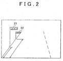
- FIG. 2 is one example of an image captured by the camera.
- the image in FIG. 2 shows traffic signals 21, 22. Since the position and orientation of the vehicle have already been determined by the GPS/INS device 2, if the position of each traffic signal 21, 22 is estimated, the region of the image in which the traffic signals 21, 22 are present can be estimated with a certain degree of accuracy.
- the shape of an object ahead of the vehicle and the distance to that object can be determined by measuring the time from when radar pulses are transmitted from the radar to when the radar pulses return to the radar.
- the radar device supplies pulse current to a laser diode and starts time count at the same time.
- the laser diode When supplied with the pulse current, the laser diode outputs laser pulses, which are proportional to the current, in the forward direction.
- the radar stops the time count. Because the counted time is proportional to the distance to the object, the distance to the object can be determined by multiplying the counted time with an appropriate coefficient.
- the radar continuously transmits laser pulses while changing the transmission direction such that a predetermined region ahead of the vehicle is scanned.
- the distance to the object can be determined at each scanning point.
- This distance information is stored in a processing unit, such as a microcomputer, and the processing unit generates image data based on the scanning directions, the distances to the object, and the orientation of the vehicle.
- the above is how the radar-based front monitoring device 4 obtains images such as shown in FIG. 2 . Note that it is difficult to distinguish different colors (such as, the signal colors of a traffic signal) in images using a radar.
- the traffic signal position estimating portion 7 of the image processing device 5 estimates the position of a traffic signal at an intersection based on the shape of the intersection. Because the present position of the vehicle is determined by the GPS/INS device 2 as described above, the map of the region around the vehicle, in particular, the map of roads in the traveling direction of the vehicle can be obtained from the map database 3, and therefore the shape of the road ahead of the vehicle can be determined. There are many traffic signals along each road, however, they are usually provided at specific positions. In the following, detailed description will be made of how the position of each traffic signal is estimated based on the presence or absence of an intersection, the shape of a road, etc.
- the image processing region setting portion 8 of the image processing device 5 sets a region of an image over which searching of traffic signals is performed, based on the positions of the traffic signals estimated by the traffic signal position estimating portion 7 and the position and orientation of the vehicle.
- FIG. 3A shows the shape of a road and the present position of the vehicle, which have been extracted from the map database 3.
- FIG. 3B shows an image captured when the position of the vehicle is detected as shown in FIG. 3A .
- the traffic signal position estimating portion 7 detects an intersection ahead of the vehicle and estimates the distance to the intersection. For example, when an intersection is detected, the traffic signal position estimating portion 7 assumes that a traffic signal is present at a corner before the intersection, and estimates the distance to the traffic signal based on the road map.
- the traffic signal is located several meters above the road surface.
- the image processing region setting portion 8 can determine the direction in which an image such as shown in FIG. 3B has been captured with respect to the intersection. That is, once the position of the traffic signal has been estimated, it is possible to identify the region of the image in which the traffic signal is likely to be present, based on the position and orientation of the vehicle. Note that the size of a search frame may be changed in accordance with the distance between the vehicle and the traffic signal.
- a search frame 51 that is a region in which a traffic signal is estimated to be present by the image processing region setting portion 8.
- the traffic signal detecting portion 9 of the image processing device 5 is only required to perform searching of the traffic signal over the region identified by the search frame 51.
- the traffic signal detecting portion 9 searches the traffic signal by processing the data of image. For example, the traffic signal detecting portion 9 searches the traffic signal by template matching. More specifically, in template marching, an image of a standard traffic signal, which is a template, is overlaid on the image and continuously displaced pixel by pixel so as to scan the entire region of the search frame 51 or the entire region of the image. During the scanning, for example, the traffic signal detecting portion 9 calculates the degree of matching between the brightness distribution of the template image and that of each scanned portion of the image, and determines the position of the temperate at which the degree of matching is highest as the position of the traffic signal. Regarding distinction of red, blue, and yellow, the position with the highest brightness among the three circles of the traffic signal is determined as being turned on.
- machine learning such as support vector machine or neutral network
- learning databases each containing a template of a traffic signal having a different size may be used.
- the leaning databases are selectively used based on the distance to the traffic signal, and therefore the accuracy of detection improves.
- the output device 6 is a liquid crystal display, an organic electroluminescent display, a head-up display, or the like, which displays road maps, traffic information, and a route to a destination.
- a speaker is connected to the output device 6.
- the speaker 6 generates a sound notifying the position of a traffic signal and a cautionary sound.
- the image processing region setting portion 8 sets a search frame. Two or more of the following methods may be used in combination provided that no conflict occurs between them. When using two or more methods that conflict each other, it is recommended that one of the methods be used in advance, and if no traffic signal is detected by that method, the next method then be used.
- FIG. 6A shows the shape of a road ahead of the vehicle, which has been extracted from the map database 3, and FIG. 6B shows an image captured when the position of the vehicle is detected as shown in FIG. 6A .
- the traffic signal position estimating portion 7 estimates a traffic signal to be located before an intersection and another traffic signal to be located behind the foregoing traffic signal by the distance substantially equal to the width of a crossing road.
- the image processing region setting portion 8 sets a search frame 55 for the traffic signal located before the intersection and a search frame 56 for the second traffic signal located after the intersection, based on the position of the vehicle, the distance to the intersection, and the orientation of the vehicle, which are obtained from the GPS/INS device 2, and based on the width of the crossing road, which is extracted from the map database 3.
- the search region can be made smaller than it is when searching of the traffic signals is performed over the entire region of the image.
- each search frame 55, 56 may be set substantially equal to the width of the road, or may be set slightly greater than the width of the road for some margin. Also, the size of the image processing region can be further reduced by making the size of the search frame 56, which is set for the traffic signal located after the intersection, smaller than the size of the search frame 55, which is set for the traffic signal located before the intersection, according to the difference in the distance from the vehicle.
- FIG. 7A shows the shape of a road ahead of the vehicle, which has been extracted from the map database 3, and FIG. 7B shows an image captured when the position of the vehicle is detected as shown in FIG. 7A .
- a "wide road” is a road having at least a certain number of lanes or having at least a certain width. In the case of an intersection of such a wide road, traffic signals are sometimes provided at the corners of the intersection so that drivers can easily find each traffic signal.
- the traffic signal position estimating portion 7 estimates a traffic signal to be located at each corner of the intersection.
- the traffic signal position estimating portion 7 estimates a traffic signal to be located at each corner of the intersection.
- the image processing region setting portion 8 sets search frames 57 to 60 for the respective corners in the image, based on the position of the vehicle, the distance to each corner, and the orientation of the vehicle, which are obtained from the GPS/INS device 2.
- each search frame may be set to be substantially half the width of the road, or to be slightly greater than the half width for some margin.
- the size of the image processing region can be further reduced by making the size of the search frames 58, 60, which are located before the intersection, smaller than the search frames 57, 59, which are located after the intersection, according to the difference in the distance from the vehicle.
- the search region can be made smaller than it is when searching of the traffic signals is performed over the entire region of the image or across the entire width of the road.
- FIG. 8A shows the shape of a road ahead of the vehicle, which has been extracted from the map database 3
- FIG. 8B shows an image captured when the position of the vehicle is detected as shown in FIG. 8A .
- the traveling direction of the vehicle and the position of a traffic signal do not match, and therefore a search frame is set in accordance with the curvature of the road.
- the position of a traffic signal for the intersection is offset frontward from the intersection by a predetermined distance so that drivers can find the traffic signal beforehand.
- the traffic signal position estimating portion 7 thus calculates the offset distance L1 (offset) and estimates the position of the traffic signal.
- the image processing region setting portion 8 sets the position of a search frame 61 based on the position of the vehicle, the angle ⁇ between the intersection and the orientation of the vehicle, and the distance to the intersection, which are obtained from the GPS/INS device 2.
- the image processing region setting portion 8 sets the position of a search frame 62 based on the offset distance L1 (offset), and based on the position of the vehicle, and the distance to the intersection, which are obtained from the GPS/INS device 2.
- each search frame 61, 62 may be set to be substantially equal to the width of the road, substantially half the width of the road, substantially equal to the width of one lane of the road, or slightly greater than each of them for some margin. Also, the size of the image processing region can be further reduced by adjusting the size of each search frame 61, 62 in accordance with the difference in the distance from the vehicle.
- the search region can be made smaller than it is when searching of the traffic signals is performed over the entire region of the image.
- FIG. 9A shows the inclination of the road, which is extracted from the map database 3
- FIG. 9B shows an image captured when the position of the vehicle is detected as shown in FIG. 9A .
- a traffic signal In the case of an intersection of an inclined road, a traffic signal is located a predetermined offset distance before the intersection so that drivers can easily find the traffic signal.
- the traffic signal position estimating portion 7 calculates the offset distance L2 based on the inclination ⁇ of the road, and the image processing region setting portion 8 sets the position of a search frame 63 based on the position of the vehicle and the distance to the intersection, which are obtained from the GPS/INS device 2.
- the width of the search frame 63 may be set to be substantially equal to the width of the road, substantially half the width of the road, substantially equal to the width of one lane of the road, or slightly greater than each of them for some margin, depending upon the width of the road.
- the search region can be made smaller than it is when searching of the traffic signal is performed over the entire region of the image.
- FIG. 10A shows the shape of a road ahead of the vehicle, which has been extracted from the map database 3, and FIG. 10B shows an image captured when the position of the vehicle is detected as shown in FIG. 10A .
- a traffic signal is sometimes located at the center of the intersection.
- the center of the intersection corresponds to the lateral center of the road or the vicinity thereof.
- the information regarding the width of the road on which the vehicle is traveling is stored in the map database 3.
- the image processing region setting portion 8 sets a search frame 64 in the image based on the position of the vehicle, the distance to the intersection, and the orientation of the vehicle, which are obtained from the GPS/INS device 2, and based on the width of each of the two roads, which are extracted from the map database 3.
- the search region can be made smaller than it is when searching of the traffic signal is performed over the entire region of the image.
- width of the search frame 64 may be set substantially equal to the width of the road, or may be set slightly greater than it for some margin.
- the image processing system 1 when the vehicle is approaching an intersection, estimates the position of each traffic signal and sets search frames in accordance with the width of the road, the shape of the road, etc.
- FIG. 11 is a flowchart indicating a control routine executed by the image processing system to detect traffic signals.
- the control routine starts in response to the ignition being turned on or to the vehicle starting moving.
- the GPS/INS device 2 obtains the position and orientation of the vehicle (S1).
- the image processing device 5 then obtains the road maps around the present position of the vehicle, especially the roads maps of the regions in the traveling direction of the vehicle (S2).
- the front monitoring device 4 obtains images at a predetermined frame rate and output the images to the image processing device 5 (S3).
- the traffic signal position estimating portion 7 estimates the position of a traffic signal based on the shape of the road extracted from the road map. That is, the traffic signal position estimating portion 7 determines whether there is an intersection (S4), and if there is an intersection (S4: YES), the traffic signal position estimating portion 7 estimates the position of the traffic signal based on the width of the road, the width of the crossing road, the curvature of the road, the inclination of the road, and so on (S5).
- the image processing region setting portion 8 sets, in the image, a search frame that covers the region in which a traffic signal is estimated to be present (S6).
- two or more search frames may be set based on the priorities assigned to the respective estimated positions.
- the traffic signal detecting portion 9 searches the traffic signal in the search frame by template matching, or the like (S7).
- the traffic signal detecting portion 9 searches the traffic signal by performing image processing to the entire image, that is, to the entire region around the intersection (S9).
- a predetermined control is performed, such as detecting the vehicle speed and notifying the driver if the detected vehicle speed is higher than a predetermined level (S10).
- FIG. 16A and 16B are images captured from the vehicle when the vehicle is traveling on a two-lane road.
- the region indicated by the frame in FIG. 16A is the search region set when image processing is performed over the entire region around the intersection, as in the conventional methods.
- Shown in FIG. 16B are search frames set based on the presumption that traffic signals are located above a road (i) and located before and after the intersection, respectively (ii) or (iii).
- FIG. 12 is a graph for comparing the time used for image processing between the case in which a conventional image processing method is used and the case in which the position of a traffic signal is estimated and a search frame is set based on the estimated position of the traffic signal.
- each of the white bars represents the time used when the entire region around the intersection is searched
- each of the black bars represents the time used when a search frame is set and searching of traffic signals is performed within the search frame.
- FIG. 12A when image processing is performed to the image shown in FIG. 16A and FIG. 16B , it takes 120 msec before detecting a traffic signal when searching of the traffic signal is performed over the entire region around the intersection, and 80 msec when the searching is performed using a search frame.
- FIG. 17A and FIG. 17B are images captured when the vehicle is traveling on a wide road. This road has three lanes.
- the region indicated by the frame in FIG. 17A is the search region set when image processing is performed over the entire region around the intersection.
- a traffic signal is estimated to be located at each corner of the intersection (iv), and search frames are set accordingly, that is, four search frames are set.
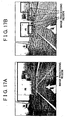
- FIG. 18A and FIG. 18B each show an image captured when the vehicle is traveling on a curve.
- the region indicated by the frame in FIG. 18A is the search region set when image processing is performed over the entire region around the intersection.
- a traffic signal is estimated to be located the offset distance L1(offset) before the intersection (v) and a search frame is set accordingly.
- FIG. 19A and FIG. 19B each show an image captured when the vehicle is traveling on an inclined road.
- the region indicated by the frame in FIG. 19A is the search region set when image processing is performed over the entire region around the intersection.
- a traffic signal is estimated to be located the offset distance L2 (offset) before the intersection (vi) and a search frame is set accordingly.
- FIG. 12D when image processing is performed to the image shown in FIG. 18A and FIG. 18B , it takes 100 msec before detecting a traffic signal when searching of the traffic signal is performed over the entire region around the intersection, and 45 msec when the searching is performed using a search frame.
- the time needed for image processing for detecting a traffic signal is reduced by estimating the position of the traffic signal and setting a search frame accordingly.
- the true coordinate of a traffic signal is calculated through predetermined calculations using, as an initial value, the position of the traffic signal which is estimated by the traffic signal position estimating portion 7 on the road map, and the calculated true coordinate of the traffic signal is recorded in a database.
- the position of a traffic signal will be referred as "the coordinate of a traffic signal" where appropriate and the coordinate of each traffic signal is defined by the latitude, longitude, and altitude.
- FIG. 13 shows one example of the configuration of the image processing system according to the second exemplary embodiment.
- the components that are the same as those in FIG. 1 will be designated by the same numerals and their description will be omitted.
- the image processing system in FIG. 13 is different from that in FIG. 1 in that the image processing system in FIG. 13 includes a traffic signal position calculating portion 11 and a spatial model database 10.
- the traffic signal position calculating portion 11 calculates the true coordinate of a traffic signal using, for example, a Kalman filter.
- the Kalman filter is a filter (algorithm) that is used to find the most appropriate estimated value, as a true value, from observed values including noises. More specifically, a Kalman filter is a state estimation type filter that applies, in calculation, the present estimated value to the previous estimated value so as to estimate a value closer to the true value.
- the true coordinate of a traffic signal is repeatedly calculated at each frame, using the values obtained from the captured images and based on the position and orientation of the vehicle.
- the traffic signal position calculating portion 11 can determine the positional relationship in three dimensions between the vehicle and the traffic signal.
- the coordinate of the detected traffic signal can be determined from the position and the orientation of the vehicle.
- the position and orientation of the vehicle include errors and therefore the calculated coordinate of the traffic signal also includes errors.
- images are continuously captured at a high rate, such as several tens of images in a second, it is considered that, as the estimation of the coordinate is thus repeated, the estimated coordinate approaches the true value.
- the coordinate that is finally recorded before the vehicle passes through the intersection is recorded, it is possible to use the recorded coordinate as an initial value when the vehicle passes through the same intersection next time, and this makes it possible to estimate a value closer to the true value.
- a spatial mode database 10 is a database that records the coordinates of traffic signals calculated by the traffic signal position calculating portion 11. That is, the spatial model database 10 records the coordinates of traffic signal that are calculated when the vehicle passes through each intersection, associating each coordinate with the corresponding intersection node and the date and time at which the vehicle passed through the intersection. Thus, from next time the vehicle passes through the same intersection, the position of the traffic signal, when setting the image processing region, can be estimated more accurately using the recorded coordinate of the traffic signal.
- FIG. 14 is a flowchart showing a control routine that the image processing system executes to detect traffic signals.
- the components that are the same as those in FIG. 11 will be designated by the same numerals.
- the GPS/INS device 2 obtains the position and orientation of the vehicle (S1).
- the image processing device 5 then obtains the road maps around the present position of the vehicle, especially the roads maps of the regions in the traveling direction of the vehicle (S2).
- the front monitoring device 4 obtains images at a predetermined frame rate and outputs the images to the image processing device 5 (S3).
- the traffic signal position estimating portion 7 estimates the position of a traffic signal based on the shape of the road that is extracted from the road map. That is, the traffic signal position estimating portion 7 determines whether there is an intersection (S4), and if there is an intersection (S4: YES), the traffic signal position estimating portion 7 estimates the position of the traffic signal based on the width of the road, the width of the crossing road, the curvature of the road, the inclination of the road, and so on (S5).
- the image processing region setting portion 8 sets, in the image, a search frame that covers the region in which a traffic signal is estimated to be located (S6). If there are two or more estimated positions of the traffic signal, two or more search frames may be set based on the priorities assigned to the respective estimated positions.
- the traffic signal detecting portion 9 detects the traffic signal from the search frame by template matching, or the like (S7).
- the traffic signal calculating portion 11 determines whether the detected traffic signal has been detected for the first time through image processing (S 18). That is, the image data of this traffic signal is regarded as having been obtained for the first time, if the first image data of the traffic signal is detected in those images that have been continuously captured by the front monitoring device 4 when the vehicle passes through an intersection for the first time.
- the traffic signal calculating portion 11 sets the coordinate of the traffic signal, which has been estimated in step S5, as the initial value for calculating the true coordinate of the traffic signal (S 19). By thus setting the initial value, the traffic signal calculating portion 11 can more easily reach the true coordinate of the traffic signal through repetition of calculations.
- the traffic signal calculating portion 11 sets the initial value to the coordinate estimated in accordance with the shape of the road (S19), and calculates the true coordinate of the traffic signal based on the position and orientation of the vehicle and the position of the traffic signal in the image (S21).
- the traffic signal calculating portion 11 repeatedly calculates the true coordinate of the traffic signal by applying, in calculation, the present position and orientation of the vehicle and the position of the traffic signal in the image to the coordinate of the traffic signal that has already been estimated (S21).
- the image processing device 5 determines whether the vehicle has passed the intersection (S10). This determination is made based on the position of the vehicle that has been obtained from the GPS/INS device 2.
- step 22 If it is determined in step 22 that the vehicle has not yet passed through the intersection (S22: NO), the control goes back to step 1 and repeats the searching of the traffic signal and the calculation of the true coordinate of the traffic signal.
- step 22 if it is determined in step 22 that the vehicle has already passed through the inter section (S22: YES), the image processing device 5 records the estimated coordinate of the traffic signal into the spatial model database (S23), after which the control routine of the flowchart in FIG. 14 ends.
- FIG. 15A, FIG. 15B, and FIG. 15C represent an example of a calculation result of the coordinate of a traffic signal according to the number of steps. More specifically, FIG. 15A represents the relation between the number of steps and the latitude, and FIG. 15B represents the relation between the number of steps and the longitude, and FIG. 15 C represents the relation between the number of steps and the altitude.
- the dotted line represents the true coordinate of the traffic signal that is obtained through an actual measurement
- line A represents the coordinate of the traffic signal that is calculated using the estimated position of the traffic signal as the initial value
- line B represents the coordinate of the traffic signal that is calculated using the position at the node of the intersection and 5m above the road surface as the initial value.
- the image processing system can prevent divergence of calculations by using an estimated position of the traffic signal as the initial value and thus accurately calculates the true coordinate of the traffic signal.
- the size of the search region of the image can be reduced presuming that the traffic signal is located at the estimated coordinate, and therefore the traffic signal can be detected promptly.
Landscapes
- Physics & Mathematics (AREA)
- General Physics & Mathematics (AREA)
- Engineering & Computer Science (AREA)
- Multimedia (AREA)
- Theoretical Computer Science (AREA)
- Life Sciences & Earth Sciences (AREA)
- Atmospheric Sciences (AREA)
- Traffic Control Systems (AREA)
- Navigation (AREA)
Claims (8)
- Bildverarbeitungssystem umfassend:eine vordere Überwachungsvorrichtung (4), die ein Bild einer Sicht vor einem Fahrzeug aufnimmt,eine Fahrzeugpositionsbestimmungsvorrichtung (2), die die Position und Orientierung des Fahrzeugs bestimmt,eine Kartendatenbank (3), die eine Straßenkarte speichert,einen Verkehrssignalanlagen-Positionsschätzteil (7), der die Position einer Verkehrssignalanlage schätzt,einen Bildverarbeitungsregioneinstellteil (8), der in dem von der vorderen Überwachungsvorrichtung (4) aufgenommenen Bild eine Bildverarbeitungsregion vorgibt, über welche eine vorgegebene Bildverarbeitung basierend auf der Position der Verkehrssignalanlage, die von dem Verkehrssignalanlagen-Positionsschätzteil (7) geschätzt worden ist, durchgeführt wird, undeinen Verkehrssignalanlagen-Erkennungsteil (9), der die Verkehrssignalanlage in der Bildverarbeitungsregion durch die vorgegebene Bildverarbeitung erkennt, wobei das Bildverarbeitungssystem dadurch gekennzeichnet ist, daß der Verkehrssignalanlagen-Positionsschätzteil (7) die Position der Verkehrssignalanlage basierend auf der Form einer Kreuzung vor dem Fahrzeug schätzt, die entsprechend der von der Fahrzeugpositionsbestimmungsvorrichtung (2) bestimmten Position des Fahrzeugs aus der Kartendatenbank (3) ausgelesen worden ist.
- Bildverarbeitungssystem nach Anspruch 1, dadurch gekennzeichnet, daß:wenn die Form der Straße eine Kreuzung anzeigt, der Verkehrssignalanlagen-Positionsschätzteil (7) schätzt, daß eine Verkehrssignalanlage oder Verkehrssignalanlagen sich befinden:a) oberhalb einer Straße, auf welcher das Fahrzeug fährt,b) jeweils vor und nach der Kreuzung, in Fahrtrichtung des Fahrzeugs gesehen,c) jeweils vor und nach der Kreuzung, in Fahrtrichtung gesehen quer entlang einer kreuzenden Straße,d) innerhalb eines vorgegebenen Abstandes von jeder Ecke der Kreuzung,e) vor der Kreuzung mit einem Abstand, der entsprechend dem Krümmungsradius einer Kurve ermittelt wird, in Fahrtrichtung des Fahrzeugs gesehen,f) vor der Kreuzung mit einem Abstand, der entsprechend einer Neigung der Straße ermittelt wird, in Fahrtrichtung des Fahrzeugs gesehen, oderg) im wesentlichen an einem seitlichen Mittelpunkt der Straße, auf welcher das Fahrzeug fährt.
- Bildverarbeitungssystem nach Anspruch 1 oder 2, dadurch gekennzeichnet, daß die Bildverarbeitungsregion basierend auf der Breite der Straße, auf welcher das Fahrzeug fährt, bestimmt wird.
- Bildverarbeitungssystem nach einem der Ansprüche 1 bis 3, dadurch gekennzeichnet, daß es ferner umfaßt:eine Ausgabevorrichtung (6), die das Bild der Sicht vor dem Fahrzeug und Textinformationen für einen Fahrer anzeigt, wobei ein Lautsprecher mit der Ausgabevorrichtung verbunden ist und der Lautsprecher eine Warnung ausgibt, wenn der Verkehrssignalanlagen-Erkennungsteil (9) die Verkehrssignalanlage erkennt.
- Bildverarbeitungssystem nach einem der Ansprüche 1 bis 4, dadurch gekennzeichnet, daß es ferner umfaßt:einen Verkehrssignalanlagen-Positionsberechnungsteil (11), der eine Koordinate der Position der Verkehrssignalanlage berechnet, wobeider Verkehrssignalanlagen-Positionsberechnungsteil (11) die Koordinate der Position der Verkehrssignalanlage unter Verwendung der Position der Verkehrssignalanlage, die von dem Verkehrssignalanlagen-Positionsschätzteil (7) basierend auf der von der Fahrzeugpositionsbestimmungsvorrichtung (2) erfaßten Position und Orientierung des Fahrzeugs und der von dem Verkehrssignalanlagen-Erkennungsteil erkannten Position der Verkehrssignalanlage in dem Bild geschätzt worden ist, als Anfangswert berechnet.
- Bildverarbeitungssystem nach Anspruch 5, dadurch gekennzeichnet, daß es ferner umfaßt:eine Raummodell-Datenbank (10), die die von dem Verkehrssignalanlagen-Positionsberechnungsteil (11) berechneten Koordinaten der Position der Verkehrssignalanlage speichert, wobei,wenn die Koordinate der Position der Verkehrssignalanlage in der Raummodell-Datenbank gespeichert ist, die gespeicherte Koordinate als Anfangswert in der Berechnung durch den Verkehrssignalanlagen-Positionsberechnungsteil (11) gesetzt wird.
- Bildverarbeitungssystem nach einem der Ansprüche 1 bis 6, dadurch gekennzeichnet, daß
die Verkehrssignalanlage eine Lichtsignalanlage umfaßt. - Verfahren zur Bildbearbeitung umfassend:Aufnehmen eines Bildes einer Sicht vor einem Fahrzeug,Bestimmen einer Position und einer Orientierung des Fahrzeugs,Auslesen einer Form einer Kreuzung vor dem Fahrzeug aus einer Straßenkartendatenbank, die eine Straßenkarte vorspeichert, basierend auf der ermittelten Position des Fahrzeugs,Schätzen der Position einer Verkehrssignalanlage,Vorgeben einer Bildverarbeitungsregion, über welche eine vorgegebene Bildverarbeitung durchgeführt wird, basierend auf der geschätzten Position der Verkehrssignalanlage, undErkennen der Verkehrssignalanlage aus der Bildverarbeitungsregion durch die vorgegebene Bildverarbeitung, dadurch gekennzeichnet, daß das Schätzen der Position der Verkehrssignalanlage auf der Form der Kreuzung basiert.
Applications Claiming Priority (2)
| Application Number | Priority Date | Filing Date | Title |
|---|---|---|---|
| JP2006060226A JP4631750B2 (ja) | 2006-03-06 | 2006-03-06 | 画像処理システム |
| PCT/IB2007/000512 WO2007102065A1 (en) | 2006-03-06 | 2007-03-02 | Image processing system and method |
Publications (2)
| Publication Number | Publication Date |
|---|---|
| EP1991973A1 EP1991973A1 (de) | 2008-11-19 |
| EP1991973B1 true EP1991973B1 (de) | 2011-05-11 |
Family
ID=38189948
Family Applications (1)
| Application Number | Title | Priority Date | Filing Date |
|---|---|---|---|
| EP07713099A Ceased EP1991973B1 (de) | 2006-03-06 | 2007-03-02 | Bildverarbeitungssystem und verfahren |
Country Status (5)
| Country | Link |
|---|---|
| US (1) | US8134480B2 (de) |
| EP (1) | EP1991973B1 (de) |
| JP (1) | JP4631750B2 (de) |
| CN (1) | CN101395645B (de) |
| WO (1) | WO2007102065A1 (de) |
Cited By (1)
| Publication number | Priority date | Publication date | Assignee | Title |
|---|---|---|---|---|
| EP3136367B1 (de) * | 2015-08-31 | 2022-12-07 | Continental Autonomous Mobility Germany GmbH | Fahrzeugkameravorrichtung sowie verfahren zur erfassung eines vorausliegenden umgebungsbereichs eines kraftfahrzeugs |
Families Citing this family (119)
| Publication number | Priority date | Publication date | Assignee | Title |
|---|---|---|---|---|
| US8892356B1 (en) * | 2003-06-19 | 2014-11-18 | Here Global B.V. | Method and system for representing traffic signals in a road network database |
| US9341485B1 (en) | 2003-06-19 | 2016-05-17 | Here Global B.V. | Method and apparatus for representing road intersections |
| KR100819047B1 (ko) * | 2006-11-27 | 2008-04-02 | 한국전자통신연구원 | 교차로 중심선 예측 장치 및 방법 |
| JP4533936B2 (ja) * | 2008-02-01 | 2010-09-01 | 日立オートモティブシステムズ株式会社 | 画像処理装置、及びこれを備えた車両検知装置 |
| JP2009187351A (ja) * | 2008-02-07 | 2009-08-20 | Fujitsu Ten Ltd | 障害物検出装置および障害物検出方法 |
| GB0802444D0 (en) * | 2008-02-09 | 2008-03-19 | Trw Ltd | Navigational device for a vehicle |
| JP5164645B2 (ja) * | 2008-04-07 | 2013-03-21 | アルパイン株式会社 | カルマンフィルタ処理における繰り返し演算制御方法及び装置 |
| JP5001911B2 (ja) * | 2008-06-30 | 2012-08-15 | アイシン・エィ・ダブリュ株式会社 | 停止義務地点学習装置及び停止義務地点学習プログラム、並びにこれを用いたナビゲーション装置 |
| US8233662B2 (en) * | 2008-07-31 | 2012-07-31 | General Electric Company | Method and system for detecting signal color from a moving video platform |
| US8229170B2 (en) * | 2008-07-31 | 2012-07-24 | General Electric Company | Method and system for detecting a signal structure from a moving video platform |
| US8559673B2 (en) * | 2010-01-22 | 2013-10-15 | Google Inc. | Traffic signal mapping and detection |
| EP2410294A1 (de) * | 2010-07-21 | 2012-01-25 | Harman Becker Automotive Systems GmbH | Verfahren und Vorrichtung zur Bereitstellung von Kosteninformation für Kreuzungen und Verfahren zur Bestimmung einer Route |
| EP2447884B1 (de) * | 2010-10-28 | 2014-12-17 | CycloMedia Technology B.V. | Verfahren zur Detektion und Wiedererkennung eines Objekts in einem Bild sowie Vorrichtung und Computerprogramm dafür |
| US8768012B2 (en) * | 2010-11-24 | 2014-07-01 | Denso Corporation | Road estimation device and method for estimating road |
| JP5747549B2 (ja) * | 2011-02-18 | 2015-07-15 | 株式会社豊田中央研究所 | 信号機検出装置及びプログラム |
| WO2012129437A2 (en) * | 2011-03-23 | 2012-09-27 | Tk Holdings Inc. | Driver assistance system |
| US20120296539A1 (en) * | 2011-03-23 | 2012-11-22 | Tk Holdings Inc. | Driver assistance system |
| US8620032B2 (en) * | 2011-05-10 | 2013-12-31 | GM Global Technology Operations LLC | System and method for traffic signal detection |
| CN102298693B (zh) * | 2011-05-18 | 2013-04-24 | 浙江大学 | 基于计算机视觉的高速公路弯道检测方法 |
| EP2528049B1 (de) * | 2011-05-23 | 2014-01-01 | Robert Bosch GmbH | Verfahren und Vorrichtung zur Erfassung von sicherheitskritischeren Objekten für ein Fahrzeug mit Hilfe von Navigationsdaten |
| CN102214409A (zh) * | 2011-06-16 | 2011-10-12 | 杭州星软科技有限公司 | 基于车辆在路线上的判断方法 |
| JP5691915B2 (ja) * | 2011-07-27 | 2015-04-01 | アイシン・エィ・ダブリュ株式会社 | 移動案内システム、移動案内装置、移動案内方法及びコンピュータプログラム |
| DE102011084993A1 (de) * | 2011-10-21 | 2013-04-25 | Robert Bosch Gmbh | Übernahme von Daten aus bilddatenbasierenden Kartendiensten in ein Assistenzsystem |
| CN103287462B (zh) * | 2012-03-01 | 2016-12-14 | 苏州华兴致远电子科技有限公司 | 机务调车信号检测方法和系统 |
| JP5480925B2 (ja) * | 2012-03-05 | 2014-04-23 | 本田技研工業株式会社 | 車両周辺監視装置 |
| CN103310648A (zh) * | 2012-03-16 | 2013-09-18 | 环达电脑(上海)有限公司 | 结合gps提示红绿灯状态信息的方法及其系统 |
| US9145140B2 (en) | 2012-03-26 | 2015-09-29 | Google Inc. | Robust method for detecting traffic signals and their associated states |
| US8761991B1 (en) | 2012-04-09 | 2014-06-24 | Google Inc. | Use of uncertainty regarding observations of traffic intersections to modify behavior of a vehicle |
| JP2013242763A (ja) * | 2012-05-22 | 2013-12-05 | Clarion Co Ltd | 対話装置、対話システム、および対話制御方法 |
| EP2667325A1 (de) * | 2012-05-22 | 2013-11-27 | Connaught Electronics Ltd. | Verfahren zur Bestimmung eines Analysebereichs in einem Kamerabild, Kamerasystem und Kraftfahrzeug mit einem Kamerasystem |
| JP5986206B2 (ja) * | 2012-07-27 | 2016-09-06 | 京セラ株式会社 | 画像処理装置、撮像装置、移動体、プログラム、および領域設定方法 |
| CN104508720B (zh) * | 2012-08-01 | 2016-09-07 | 丰田自动车株式会社 | 驾驶辅助装置 |
| CN103680176B (zh) * | 2012-09-18 | 2016-04-27 | 中国移动通信集团公司 | 基于位置信息的信号灯识别系统 |
| CN102915647A (zh) * | 2012-10-16 | 2013-02-06 | 延锋伟世通电子科技(上海)有限公司 | 一种车载交通指示牌自动识别方法和装置 |
| DE102012110219A1 (de) * | 2012-10-25 | 2014-04-30 | Continental Teves Ag & Co. Ohg | Verfahren und Vorrichtung zur Erkennung von gekennzeichneten Gefahr- und/oder Baustellen im Bereich von Fahrbahnen |
| DE102012111740A1 (de) * | 2012-12-03 | 2014-06-05 | Continental Teves Ag & Co. Ohg | Verfahren zur Unterstützung eines eine Ampel detektierenden Ampelphasenassistenten eines Fahrzeugs |
| DE102012023867A1 (de) * | 2012-12-06 | 2014-06-12 | GM Global Technology Operations LLC (n. d. Gesetzen des Staates Delaware) | Verkehrsampelerkennung |
| DE102012111933A1 (de) * | 2012-12-07 | 2014-06-12 | Conti Temic Microelectronic Gmbh | Verfahren und vorrichtung zum automatischen erkennen und interpretieren von lichtsignalanlagen |
| JP5754470B2 (ja) * | 2012-12-20 | 2015-07-29 | 株式会社デンソー | 路面形状推定装置 |
| CN103065489B (zh) * | 2012-12-28 | 2015-10-21 | 天津爱迪尔软件开发有限公司 | 一种即时导航路况系统及导航方法 |
| CN104937648A (zh) * | 2013-01-25 | 2015-09-23 | 丰田自动车株式会社 | 道路环境识别系统 |
| JP6194604B2 (ja) * | 2013-03-15 | 2017-09-13 | 株式会社リコー | 認識装置、車両及びコンピュータが実行可能なプログラム |
| CN105074794B (zh) * | 2013-04-04 | 2017-10-24 | 日产自动车株式会社 | 信号识别装置 |
| US9164511B1 (en) | 2013-04-17 | 2015-10-20 | Google Inc. | Use of detected objects for image processing |
| US9654738B1 (en) | 2013-08-07 | 2017-05-16 | Waymo Llc | Using multiple exposures to improve image processing for autonomous vehicles |
| US9558408B2 (en) * | 2013-10-15 | 2017-01-31 | Ford Global Technologies, Llc | Traffic signal prediction |
| US9495602B2 (en) | 2013-10-23 | 2016-11-15 | Toyota Motor Engineering & Manufacturing North America, Inc. | Image and map-based detection of vehicles at intersections |
| EP3742339A1 (de) | 2013-12-04 | 2020-11-25 | Mobileye Vision Technologies Ltd. | System und verfahren zur durchführung eines mehrsegment-bremsprofils für ein fahrzeug |
| CN103729863B (zh) * | 2013-12-06 | 2016-05-25 | 南京金智视讯技术有限公司 | 基于自主学习的交通信号灯全自动定位识别的方法 |
| WO2015116950A1 (en) | 2014-01-30 | 2015-08-06 | Anna Clarke | Systems and methods for lane end recognition |
| JP5962689B2 (ja) * | 2014-02-14 | 2016-08-03 | トヨタ自動車株式会社 | 自律移動体、及びその故障判定方法 |
| CN104835341B (zh) * | 2014-03-14 | 2017-12-08 | 北汽福田汽车股份有限公司 | 用于车辆中的红绿灯提醒装置及系统 |
| CN105023452B (zh) * | 2014-04-24 | 2017-09-29 | 深圳市赛格导航科技股份有限公司 | 一种多路交通信号灯信号采集的方法及装置 |
| CN103955705B (zh) * | 2014-04-29 | 2017-11-28 | 银江股份有限公司 | 基于视频分析的交通信号灯定位、识别与分类方法 |
| EP3147629B1 (de) * | 2014-05-20 | 2019-07-10 | Nissan Motor Co., Ltd | Objekterkennungsvorrichtung und objekterkennungsverfahren |
| WO2015186002A2 (en) | 2014-06-03 | 2015-12-10 | Mobileye Vision Technologies Ltd. | Systems and methods for detecting an object |
| KR102233391B1 (ko) * | 2014-06-16 | 2021-03-29 | 팅크웨어(주) | 전자 장치, 전자 장치의 제어 방법 및 컴퓨터 판독 가능한 기록 매체 |
| MX354764B (es) * | 2014-07-08 | 2018-03-21 | Nissan Motor | Dispositivo de deteccion de semaforo y metodo de deteccion de semaforo. |
| JP6331811B2 (ja) * | 2014-07-18 | 2018-05-30 | 日産自動車株式会社 | 信号機検出装置及び信号機検出方法 |
| US9707960B2 (en) | 2014-07-31 | 2017-07-18 | Waymo Llc | Traffic signal response for autonomous vehicles |
| DE102014111126A1 (de) * | 2014-08-05 | 2016-02-11 | Valeo Schalter Und Sensoren Gmbh | Verfahren zum Erzeugen einer Umgebungskarte eines Umgebungsbereichs eines Kraftfahrzeugs, Fahrerassistenzsystem sowie Kraftfahrzeug |
| JP6299517B2 (ja) * | 2014-08-08 | 2018-03-28 | 日産自動車株式会社 | 信号機認識装置及び信号機認識方法 |
| JP6365103B2 (ja) * | 2014-08-14 | 2018-08-01 | 日産自動車株式会社 | 信号機検出装置及び信号機検出方法 |
| US9305224B1 (en) * | 2014-09-29 | 2016-04-05 | Yuan Ze University | Method for instant recognition of traffic lights countdown image |
| US10380437B2 (en) * | 2014-10-14 | 2019-08-13 | Toyota Motor Europe | Systems and methods for traffic sign assistance |
| JP2016088325A (ja) * | 2014-11-06 | 2016-05-23 | 三菱重工業株式会社 | 進行方向監視装置、進行方向監視方法およびプログラム |
| JP6307767B2 (ja) * | 2014-11-06 | 2018-04-11 | 三菱重工業株式会社 | 進行方向監視装置、進行方向監視方法およびプログラム |
| CN112945251B (zh) * | 2015-02-10 | 2022-06-28 | 御眼视觉技术有限公司 | 用于确定车道分配的系统、方法及计算机可读存储介质 |
| JP6380936B2 (ja) * | 2015-03-30 | 2018-08-29 | シャープ株式会社 | 移動体及びシステム |
| JP2016206774A (ja) * | 2015-04-17 | 2016-12-08 | トヨタ自動車株式会社 | 立体物検出装置及び立体物検出方法 |
| RU2668782C1 (ru) * | 2015-06-05 | 2018-10-02 | Ниссан Мотор Ко., Лтд. | Устройство выявления светофора и способ выявления светофора |
| JP6432680B2 (ja) * | 2015-06-09 | 2018-12-12 | 日産自動車株式会社 | 信号機検出装置及び信号機検出方法 |
| KR20190097326A (ko) | 2015-07-13 | 2019-08-20 | 닛산 지도우샤 가부시키가이샤 | 신호기 인식 장치 및 신호기 인식 방법 |
| MX361911B (es) * | 2015-07-13 | 2018-12-19 | Nissan Motor | Dispositivo de reconocimiento de semaforo y metodo de reconocimiento de semaforo. |
| US9747508B2 (en) * | 2015-07-24 | 2017-08-29 | Honda Motor Co., Ltd. | Surrounding environment recognition device |
| JP6774948B2 (ja) * | 2015-07-29 | 2020-10-28 | 京セラ株式会社 | 判定装置、車両および判定方法 |
| DE102015214622A1 (de) * | 2015-07-31 | 2017-02-02 | Bayerische Motoren Werke Aktiengesellschaft | Verfahren zum Verifizieren der Erkennung von Verkehrsleitzeichen |
| CN105069842A (zh) * | 2015-08-03 | 2015-11-18 | 百度在线网络技术(北京)有限公司 | 道路三维模型的建模方法和装置 |
| TWM518383U (zh) * | 2015-08-07 | 2016-03-01 | yi-jun Shen | 智能單畫面號誌指示裝置 |
| CN105279511B (zh) * | 2015-10-20 | 2020-04-07 | 浙江宇视科技有限公司 | 基于颜色时变特征的交通信号灯重定位方法及装置 |
| JP6762090B2 (ja) * | 2015-11-11 | 2020-09-30 | 日立オートモティブシステムズ株式会社 | 物体検出装置 |
| CN105489035B (zh) * | 2015-12-29 | 2018-03-30 | 大连楼兰科技股份有限公司 | 应用在主动驾驶技术中检测交通信号灯的方法 |
| US9909894B2 (en) | 2016-01-07 | 2018-03-06 | Here Global B.V. | Componentized junction models |
| US9990548B2 (en) * | 2016-03-09 | 2018-06-05 | Uber Technologies, Inc. | Traffic signal analysis system |
| US10234294B2 (en) | 2016-04-01 | 2019-03-19 | Here Global B.V. | Road geometry matching with componentized junction models |
| CN106023623A (zh) * | 2016-07-28 | 2016-10-12 | 南京理工大学 | 基于机器视觉的车载交通信号与标志的识别及预警方法 |
| JP6712775B2 (ja) * | 2016-08-12 | 2020-06-24 | パナソニックIpマネジメント株式会社 | 路面推定装置、車両制御装置、路面推定方法、およびプログラム |
| CN107886033B (zh) * | 2016-09-30 | 2021-04-20 | 比亚迪股份有限公司 | 识别圆形交通灯的方法、装置及车辆 |
| JP6825299B2 (ja) * | 2016-10-24 | 2021-02-03 | 株式会社リコー | 情報処理装置、情報処理方法およびプログラム |
| JP6859659B2 (ja) * | 2016-10-25 | 2021-04-14 | 株式会社リコー | 情報処理装置、情報処理方法およびプログラム |
| CN107992788B (zh) * | 2016-10-27 | 2020-09-15 | 比亚迪股份有限公司 | 识别交通灯的方法、装置及车辆 |
| KR102826622B1 (ko) * | 2017-01-17 | 2025-06-27 | 팅크웨어(주) | 카메라의 촬영 영상을 이용한 운전 안내 제공 방법, 운전 안내 제공 장치, 전자 장치, 컴퓨터 프로그램 및 컴퓨터 판독 가능한 기록 매체 |
| US10139832B2 (en) * | 2017-01-26 | 2018-11-27 | Intel Corporation | Computer-assisted or autonomous driving with region-of-interest determination for traffic light analysis |
| DE102017203236A1 (de) * | 2017-02-28 | 2018-08-30 | Conti Temic Microelectronic Gmbh | Vorrichtung und Verfahren zum Detektieren einer Ampelphase für ein Kraftfahrzeug |
| CN106971553A (zh) * | 2017-04-13 | 2017-07-21 | 合肥圣博瑞科技有限公司 | 电子警察智能补光的系统 |
| US10699142B2 (en) * | 2017-04-20 | 2020-06-30 | GM Global Technology Operations LLC | Systems and methods for traffic signal light detection |
| CN106910358B (zh) * | 2017-04-21 | 2019-09-06 | 百度在线网络技术(北京)有限公司 | 用于无人车的姿态确定方法和装置 |
| JP6838483B2 (ja) * | 2017-04-28 | 2021-03-03 | いすゞ自動車株式会社 | 車両制御装置 |
| JP6505199B2 (ja) * | 2017-11-24 | 2019-04-24 | 株式会社ゼンリン | 運転支援システム、プログラム |
| US10458810B2 (en) * | 2017-12-21 | 2019-10-29 | GM Global Technology Operations LLC | Traffic light state assessment |
| JP6939615B2 (ja) | 2018-02-02 | 2021-09-22 | トヨタ自動車株式会社 | 信号機認識装置 |
| US11334753B2 (en) | 2018-04-30 | 2022-05-17 | Uatc, Llc | Traffic signal state classification for autonomous vehicles |
| CN109035832A (zh) * | 2018-09-12 | 2018-12-18 | 清华大学苏州汽车研究院(吴江) | 基于v2x通信的信号灯路口智能通行系统 |
| JP7147464B2 (ja) * | 2018-10-24 | 2022-10-05 | トヨタ自動車株式会社 | 画像選択装置及び画像選択方法 |
| CN111127923B (zh) * | 2018-10-31 | 2021-01-29 | 驭势科技(北京)有限公司 | 一种指示标识的解析设备和方法 |
| JP7205695B2 (ja) * | 2019-02-18 | 2023-01-17 | トヨタ自動車株式会社 | 運転支援システム |
| PH12019050076A1 (en) | 2019-05-06 | 2020-12-02 | Samsung Electronics Co Ltd | Enhancing device geolocation using 3d map data |
| WO2021094799A1 (ja) * | 2019-11-12 | 2021-05-20 | 日産自動車株式会社 | 信号機認識方法及び信号機認識装置 |
| EP4071712B1 (de) | 2019-11-21 | 2025-08-27 | Trigo Vision Ltd. | Artikelidentifikations- und -verfolgungssystem |
| US12036990B2 (en) * | 2019-11-22 | 2024-07-16 | Magna Electronics Inc. | Vehicular control system with controlled vehicle stopping and starting at intersection |
| US11335100B2 (en) * | 2019-12-27 | 2022-05-17 | Industrial Technology Research Institute | Traffic light recognition system and method thereof |
| TWI743637B (zh) * | 2019-12-27 | 2021-10-21 | 財團法人工業技術研究院 | 號誌辨識系統及其方法 |
| US12112550B2 (en) * | 2020-01-07 | 2024-10-08 | Motional Ad Llc | Systems and methods for traffic light detection |
| EP3859684A1 (de) * | 2020-01-30 | 2021-08-04 | Toyota Jidosha Kabushiki Kaisha | Verfahren und system zur erstellung einer an die beleuchtung anpassbaren karte einer innenszene und deren verwendung zur schätzung einer unbekannten lichteinstellung |
| CN111639656A (zh) * | 2020-05-28 | 2020-09-08 | 东软睿驰汽车技术(沈阳)有限公司 | 交通信号灯识别方法及装置 |
| US11527156B2 (en) * | 2020-08-03 | 2022-12-13 | Toyota Research Institute, Inc. | Light emitting component-wise traffic light state, signal, and transition estimator |
| CN112489466B (zh) * | 2020-11-27 | 2022-02-22 | 恒大新能源汽车投资控股集团有限公司 | 交通信号灯识别方法和装置 |
| CN112580571A (zh) * | 2020-12-25 | 2021-03-30 | 北京百度网讯科技有限公司 | 车辆行驶的控制方法、装置及电子设备 |
| JP7794591B2 (ja) * | 2021-09-22 | 2026-01-06 | 日本信号株式会社 | 信号現示を特定するシステム |
Family Cites Families (14)
| Publication number | Priority date | Publication date | Assignee | Title |
|---|---|---|---|---|
| JP3263699B2 (ja) | 1992-12-22 | 2002-03-04 | 三菱電機株式会社 | 走行環境監視装置 |
| JP3064759B2 (ja) * | 1993-09-28 | 2000-07-12 | 株式会社日立製作所 | 車両の周囲を監視する装置、車両の運転支援システムおよび運転支援装置 |
| KR100224326B1 (ko) * | 1995-12-26 | 1999-10-15 | 모리 하루오 | 차량용 네비게이션장치 |
| JP3811238B2 (ja) | 1996-12-16 | 2006-08-16 | トヨタ自動車株式会社 | 画像情報を利用した車両用音声案内装置 |
| JP3619628B2 (ja) * | 1996-12-19 | 2005-02-09 | 株式会社日立製作所 | 走行環境認識装置 |
| US6266442B1 (en) * | 1998-10-23 | 2001-07-24 | Facet Technology Corp. | Method and apparatus for identifying objects depicted in a videostream |
| US6891960B2 (en) * | 2000-08-12 | 2005-05-10 | Facet Technology | System for road sign sheeting classification |
| JP2004334808A (ja) * | 2003-05-12 | 2004-11-25 | Nissan Motor Co Ltd | 起動判断装置 |
| JP4370869B2 (ja) | 2003-09-25 | 2009-11-25 | トヨタ自動車株式会社 | 地図データ更新方法および地図データ更新装置 |
| EP1711006B1 (de) * | 2004-01-26 | 2018-12-12 | NEC Corporation | Videotyp-feststellungssystem, videoverarbeitungssystem, videoverarbeitungsverfahren und videoverarbeitungsprogramm |
| JP4475015B2 (ja) * | 2004-06-01 | 2010-06-09 | トヨタ自動車株式会社 | 車両周辺監視装置及び車両周辺監視方法 |
| JP4506299B2 (ja) * | 2004-06-17 | 2010-07-21 | トヨタ自動車株式会社 | 車両周辺監視装置 |
| JP4321821B2 (ja) * | 2005-01-28 | 2009-08-26 | アイシン・エィ・ダブリュ株式会社 | 画像認識装置及び画像認識方法 |
| CN2795984Y (zh) * | 2005-04-06 | 2006-07-12 | 丁斌 | 一种汽车用红绿灯识别装置 |
-
2006
- 2006-03-06 JP JP2006060226A patent/JP4631750B2/ja not_active Expired - Fee Related
-
2007
- 2007-03-02 WO PCT/IB2007/000512 patent/WO2007102065A1/en not_active Ceased
- 2007-03-02 CN CN2007800078273A patent/CN101395645B/zh not_active Expired - Fee Related
- 2007-03-02 EP EP07713099A patent/EP1991973B1/de not_active Ceased
- 2007-03-02 US US12/224,791 patent/US8134480B2/en active Active
Cited By (1)
| Publication number | Priority date | Publication date | Assignee | Title |
|---|---|---|---|---|
| EP3136367B1 (de) * | 2015-08-31 | 2022-12-07 | Continental Autonomous Mobility Germany GmbH | Fahrzeugkameravorrichtung sowie verfahren zur erfassung eines vorausliegenden umgebungsbereichs eines kraftfahrzeugs |
Also Published As
| Publication number | Publication date |
|---|---|
| CN101395645A (zh) | 2009-03-25 |
| CN101395645B (zh) | 2010-06-09 |
| JP4631750B2 (ja) | 2011-02-16 |
| US8134480B2 (en) | 2012-03-13 |
| JP2007241469A (ja) | 2007-09-20 |
| EP1991973A1 (de) | 2008-11-19 |
| US20090303077A1 (en) | 2009-12-10 |
| WO2007102065A1 (en) | 2007-09-13 |
Similar Documents
| Publication | Publication Date | Title |
|---|---|---|
| EP1991973B1 (de) | Bildverarbeitungssystem und verfahren | |
| EP2065835B1 (de) | Bilderkennungsvorrichtung und Bilderkennungsprogramm | |
| CN106352867B (zh) | 用于确定车辆自身位置的方法和设备 | |
| US8725412B2 (en) | Positioning device | |
| US12359921B2 (en) | Vehicle control device and host vehicle position estimation method | |
| JP5761162B2 (ja) | 車両位置推定装置 | |
| US12272244B2 (en) | Information processing device, information processing method, and program | |
| CN102792316B (zh) | 交通信号的映射和检测 | |
| US8155873B2 (en) | Vehicle-position-recognition apparatuses, methods, and programs | |
| US8346473B2 (en) | Lane determining device, lane determining method and navigation apparatus using the same | |
| JP6870475B2 (ja) | 車線情報出力方法および車線情報出力装置 | |
| CN108573611B (zh) | 一种限速标识融合方法以及限速标识融合系统 | |
| RU2661963C1 (ru) | Устройство вычисления маршрута движения | |
| CN112074885A (zh) | 车道标志定位 | |
| JP2011511281A (ja) | センサにより検出されたオブジェクトとマップマッチングする方法 | |
| WO2015173034A1 (en) | Method and system for determining a position relative to a digital map | |
| EP3813020A1 (de) | Schätzung der ausrichtung einer kamera | |
| US20230296401A1 (en) | Apparatus, method, and computer program for determining sections for map update | |
| JP2007241468A (ja) | 車線変更検出装置 | |
| JP7723348B2 (ja) | 走行レーン推定システム |
Legal Events
| Date | Code | Title | Description |
|---|---|---|---|
| PUAI | Public reference made under article 153(3) epc to a published international application that has entered the european phase |
Free format text: ORIGINAL CODE: 0009012 |
|
| 17P | Request for examination filed |
Effective date: 20080905 |
|
| AK | Designated contracting states |
Kind code of ref document: A1 Designated state(s): DE FR GB |
|
| RBV | Designated contracting states (corrected) |
Designated state(s): DE FR GB |
|
| 17Q | First examination report despatched |
Effective date: 20090623 |
|
| GRAP | Despatch of communication of intention to grant a patent |
Free format text: ORIGINAL CODE: EPIDOSNIGR1 |
|
| DAX | Request for extension of the european patent (deleted) | ||
| GRAS | Grant fee paid |
Free format text: ORIGINAL CODE: EPIDOSNIGR3 |
|
| GRAA | (expected) grant |
Free format text: ORIGINAL CODE: 0009210 |
|
| AK | Designated contracting states |
Kind code of ref document: B1 Designated state(s): DE FR GB |
|
| REG | Reference to a national code |
Ref country code: GB Ref legal event code: FG4D |
|
| REG | Reference to a national code |
Ref country code: DE Ref legal event code: R096 Ref document number: 602007014479 Country of ref document: DE Effective date: 20110622 |
|
| PLBE | No opposition filed within time limit |
Free format text: ORIGINAL CODE: 0009261 |
|
| STAA | Information on the status of an ep patent application or granted ep patent |
Free format text: STATUS: NO OPPOSITION FILED WITHIN TIME LIMIT |
|
| 26N | No opposition filed |
Effective date: 20120214 |
|
| REG | Reference to a national code |
Ref country code: DE Ref legal event code: R097 Ref document number: 602007014479 Country of ref document: DE Effective date: 20120214 |
|
| REG | Reference to a national code |
Ref country code: GB Ref legal event code: 746 Effective date: 20121219 |
|
| REG | Reference to a national code |
Ref country code: DE Ref legal event code: R084 Ref document number: 602007014479 Country of ref document: DE Effective date: 20121213 |
|
| REG | Reference to a national code |
Ref country code: FR Ref legal event code: PLFP Year of fee payment: 10 |
|
| REG | Reference to a national code |
Ref country code: FR Ref legal event code: PLFP Year of fee payment: 11 |
|
| REG | Reference to a national code |
Ref country code: FR Ref legal event code: PLFP Year of fee payment: 12 |
|
| PGFP | Annual fee paid to national office [announced via postgrant information from national office to epo] |
Ref country code: GB Payment date: 20220127 Year of fee payment: 16 Ref country code: DE Payment date: 20220203 Year of fee payment: 16 |
|
| PGFP | Annual fee paid to national office [announced via postgrant information from national office to epo] |
Ref country code: FR Payment date: 20220209 Year of fee payment: 16 |
|
| P01 | Opt-out of the competence of the unified patent court (upc) registered |
Effective date: 20230427 |
|
| REG | Reference to a national code |
Ref country code: DE Ref legal event code: R119 Ref document number: 602007014479 Country of ref document: DE |
|
| GBPC | Gb: european patent ceased through non-payment of renewal fee |
Effective date: 20230302 |
|
| PG25 | Lapsed in a contracting state [announced via postgrant information from national office to epo] |
Ref country code: GB Free format text: LAPSE BECAUSE OF NON-PAYMENT OF DUE FEES Effective date: 20230302 |
|
| PG25 | Lapsed in a contracting state [announced via postgrant information from national office to epo] |
Ref country code: GB Free format text: LAPSE BECAUSE OF NON-PAYMENT OF DUE FEES Effective date: 20230302 Ref country code: FR Free format text: LAPSE BECAUSE OF NON-PAYMENT OF DUE FEES Effective date: 20230331 Ref country code: DE Free format text: LAPSE BECAUSE OF NON-PAYMENT OF DUE FEES Effective date: 20231003 |