EP2065835B1 - Bilderkennungsvorrichtung und Bilderkennungsprogramm - Google Patents
Bilderkennungsvorrichtung und Bilderkennungsprogramm Download PDFInfo
- Publication number
- EP2065835B1 EP2065835B1 EP08170232.6A EP08170232A EP2065835B1 EP 2065835 B1 EP2065835 B1 EP 2065835B1 EP 08170232 A EP08170232 A EP 08170232A EP 2065835 B1 EP2065835 B1 EP 2065835B1
- Authority
- EP
- European Patent Office
- Prior art keywords
- lane mark
- detected
- distance
- lane
- frame
- Prior art date
- Legal status (The legal status is an assumption and is not a legal conclusion. Google has not performed a legal analysis and makes no representation as to the accuracy of the status listed.)
- Not-in-force
Links
Images


Classifications
-
- G—PHYSICS
- G06—COMPUTING OR CALCULATING; COUNTING
- G06V—IMAGE OR VIDEO RECOGNITION OR UNDERSTANDING
- G06V20/00—Scenes; Scene-specific elements
- G06V20/50—Context or environment of the image
- G06V20/56—Context or environment of the image exterior to a vehicle by using sensors mounted on the vehicle
- G06V20/588—Recognition of the road, e.g. of lane markings; Recognition of the vehicle driving pattern in relation to the road
Definitions
- the present invention relates to an image recognition apparatus and an image recognition program of acquiring image information including at least an image of a road surface in an area close to a vehicle, and determining the type of a lane mark included in the image information by performing an image recognition process on the acquired image information.
- a running lane recognition apparatus is disclosed in Japanese Unexamined Patent Application Publication No. 2005-322166 .
- this running lane recognition apparatus an image is taken and the taken image is converted into a plan-view image of a road viewed from vertically above by performing a coordinate transformation process. Thereafter, using the plan-view image, lane mark lengths are determined for those detected in two areas defined in the plan-view image, wherein the two areas are defined at locations adjacent in the same direction as the running direction of the vehicle. If the lengths detected for the lane mark are greater than a predetermined value in both areas, it is determined that the lane mark is a solid line.
- the running lane recognition apparatus determines the lane in which the vehicle is running.
- a coordinate transformation process is first performed to convert a taken image into a plan-view image of a road viewed from vertically above. Thereafter, a plurality of lane detection areas are set in one frame of plan-view image, and the integral intensity is calculated for each area. If the calculated integral intensity is substantially constant for the plurality of areas, it is determined that the lane mark of interest is of a solid line.
- the running lane recognition apparatus determines a lane in which a vehicle of a user is running.
- US 2006/239509 A1 discloses a road line recognition apparatus, including: an imaging section imaging a progress path of a own vehicle including a road to output a couple of images; an image processing section calculating a distance in a real space in a set region of at least an image on one side based on the imaged couple of images; and a detection section detecting a road line; wherein the detection section includes: a road line candidate point detection and conversion processing unit detecting a pixel on a road surface as a road line candidate point based on luminance and the distance with regard to the image on one side, and performing Hough conversion of the road line candidate point; a road line straight line detection processing unit detecting one straight line proper to the road line on each of a right side and a left side of the own vehicle based on at least a position or a behavior of the own vehicle between straight lines obtained by the Hough conversion; and a road line detection processing unit detecting the road line of a shape of a straight line or a curved line by recording a road line position
- a central processing part segments an area in which no existence of an obstacle on a road can be previously assumed from a road image obtained from an imaging apparatus and prepares a partial image.
- the central processing part extracts a partial section line from the prepared partial image, discriminates the features of section lines drawn on both the sides of the traveling lane of the vehicle on the basis of the extracted section line and discriminates the sort of the traveling lane of the vehicle on the basis of the discriminated features of the section lines.
- the discrimination of the sort of the traveling lane is performed on coordinate converted image data which is prepared by converting UV coordinate values (image coordinates) into XY coordinate values which are coordinate values in the XY coordinate system (parallel to the road surface).
- an object of the present invention is to provide an image recognition apparatus and an image recognition program capable of accurately recognizing the type of a lane mark without needing complicated processing.
- the present invention provides an image recognition apparatus as set out in independent claim 1.
- the acquired image information is subjected to the very simple image recognition process to detect a leading end and a trailing end of a lane mark included in the detection area defined in each frame, and no complicated process such as a coordinate transformation process is necessary. This leads to a reduction in processing load imposed on the image recognition apparatus.
- the distance from one of a leading end and a trailing end of a lane mark to the other one is detected on the basis of the speed of the vehicle and the number of frames between a frame in which one of the leading end and the trailing end of the lane mark is detected and a frame in which the other one of the leading end and the trailing end of the lane mark is detected, and the lane mark type is determined on the basis of the detected distance.
- the distance the vehicle travels per frame of image information which varies depending on the vehicle speed, is first determined by using a table or by a calculation. Thereafter, the distance the vehicle travels per frame is multiplied by the number of frames between a frame in which one of a leading end and a trailing end of a lane mark is detected and a frame in which the other one of the leading end and the trailing end of the lane mark is detected.
- the resultant product indicates the distance from one of the leading end and the trailing end of the lane mark to the other one, and thus the detected distance can be easily obtained.
- a leading end and a trailing end of a lane mark are detected in an area close to the location common for the plurality of frames of image information. This leads to a reduction in frame-to-frame variation in positional relationship between the vehicle and the leading end or the trailing end of the lane mark. Thus, it is possible to increase the accuracy of the detected distance indicating the distance from one of the leading end and the trailing end of the lane mark to the other one.
- an image recognition apparatus as set out in dependent claim 2.
- the detected distance indicating the distance from one of a leading end and a trailing end to the other one of a lane mark corresponds to the length of a segment or a space of a broken-line lane mark.
- an image recognition apparatus as set out in dependent claim 3.
- segment length is used to describe the length of one segment
- segment space length is used to describe the length of the space between two adjacent segments.
- the detected distance indicating the distance from one of a leading end and a trailing end of a broken-line lane mark corresponds to the segment length or the segment space length of the broken-line lane mark, and thus it is possible to correctly determine a particular type of broken-line lane mark from a plurality of broken-line lane marks.
- an image recognition apparatus as set out in dependent claim 4.
- an image recognition apparatus as set out in dependent claim 5.
- leading ends and/or trailing ends can be detected a plurality of times at regular intervals. This phenomenon can be advantageously used to correctly determine the broken-line lane mark type.
- an image recognition apparatus as set out in dependent claw 6.
- the solid-line detection threshold value so as to be greater than the greatest segment length of all actually existing broken-line lane marks, it becomes possible to determine whether a lane mark of interest is of the solid line type by checking whether the detected distance from a leading end to a trailing end of the lane mark is greater than the solid-line detection threshold value. That is, it becomes possible to correctly distinguish solid-line lane marks extending continuously with no break from broken-line lane marks or other road markings.
- an image recognition apparatus as set out in dependent claim 7.
- the lane mark type can be determined by determining in which one of the ranges of lane mark types the distance detected by the distance detection unit falls. This makes it possible to accurately determine the lane mark type by a simple process.
- the detected distance indicating the distance from one of a leading end and a trailing end to the other one of the lane mark corresponds to the length of a segment or a space of the broken-line lane mark.
- the determination rule may as an example define the detected distance range for each of a plurality of types of broken-line lane marks that are different in one or both of segment length and segment space.
- the determination rule may as an example define a plurality of detected distance ranges for each lane mark type.
- a plurality of ranges of the detected detection for each lane mark type are defined so as to adapt to differences in segment length and/or space length of the same lane mark types depending on the road type and/or the region.
- the determination rule may as an example define a lower limit of the range of the detected distance as measured from a leading end of a lane mark, for a solid-line lane mark type.
- the lower limit of the range of the detected distance from a leading end of a lane mark is set to be greater than the greatest segment length of all actually existing broken-line lane marks, and thus it is possible to correctly distinguish solid-line lane marks extending continuously with no break from broken-line lane marks or other road markings.
- the present invention also provides a navigation apparatus as set out in claim 9.
- the lane in which the vehicle is running is detected on the basis of the type of the lane mark located close to the vehicle, and various kinds of guidance information can be provided depending on the detected type of the lane
- the present invention also provides a running lane determination apparatus as set out in claim 10.
- the present invention also provides an image recognition program as set out in independent claim 11.
- the acquired image information is subjected to the very simple image recognition process to detect a leading end and a trailing end of a lane mark included in the detection area defined in each frame, and no complicated process such as a coordinate transformation process is necessary.
- the distance from one of a leading end and a trailing end of a lane mark to the other one is detected on the basis of the speed of the vehicle and the number of frames between a frame in which one of the leading end and the trailing end of the lane mark is detected and a frame in which the other one of the leading end and the trailing end of the lane mark is detected, and the lane mark type is determined on the basis of the detected distance.
- FIG. 1 is a block diagram illustrating a configuration of the navigation apparatus 1 according to the present embodiment of the invention.
- the navigation apparatus 1 is capable of operating as the image recognition apparatus 2 configured to acquire image information G of a plurality of frames of images of a road surface Ro (see Fig. 3 ) in an area close to the vehicle C, detect leading and trailing ends of a lane mark, detect the distance from one of the leading and trailing ends of the lane mark to the other end, and determine the lane mark type on the basis of the detected distance.
- the navigation apparatus 1 also has a capability of functioning as a running lane determination apparatus 3 configured to determine a lane in which a vehicle C is running, on the basis of the lane mark type determined by the image recognition apparatus 2.
- the navigation apparatus 1 also has ordinary navigation functions. That is, the navigation apparatus 1 is capable of acquiring vehicle position information P indicating the current position and the running direction of the vehicle C, acquiring map information M from the map database 26, and providing various services on the basis of the acquired information.
- the services include displaying the vehicle position on the map, searching for a route from a starting point to a destination, providing guidance associated with the route to the destination, etc.
- the navigation apparatus 1 includes various functional units such as an image information acquisition unit 12, a vehicle position information acquisition unit 16, a navigation processing unit 17, an image recognition unit 31, a distance detection unit 32, a lane mark type determination unit 33, and a running lane determination unit 36.
- These functional units are implemented by hardware or software (a program) or by a combination of hardware and software using a central processing unit (CPU) or the like.
- the CPU may be disposed for each functional unit, or a single CPU may be shared by a plurality of functional units.
- the functional units described above are adapted to transmit/receive information among them.
- the map database 26 may be implemented using hardware such as a combination of a storage medium capable of storing information and a drive unit configured to drive the storage medium.
- the map database 26 may be implemented using, for example, a hard disk drive, a DVD drive including a DVD-ROM disk, a CD drive including a CD-ROM disk, or the like.
- a hard disk drive for example, a hard disk drive, a DVD drive including a DVD-ROM disk, a CD drive including a CD-ROM disk, or the like.
- the units of the navigation apparatus 1 according to the present embodiment are described in further detail below.
- the map database 26 functions as a map information storage unit in which map information M including map information associated with a plurality of regions is stored.
- Fig. 2 is a diagram illustrating an example of the map information M stored in the map database 26.
- the map information M includes road information Ra representing a road network on the basis of a connection relationship among a large number of nodes, n, corresponding to intersections and links k corresponding to roads between adjacent intersections.
- Each node n has information indicating a location (coordinates) on a map by latitude and longitude.
- Each two adjacent links k are connected to each other via a node n.
- Each link k has attribute information indicating a road type, a link length, a road width, and a shape interpolation point by which to represent a link shape.
- the road type information is information indicating a road type such as an expressway, a national road, a prefectural road, a general road, a narrow street, or a slip road. Note that in Fig. 2 , the road information Ra is shown only for one block but the road information Ra of other blocks is not shown.
- the road information Ra is used in various processes such as a map matching process, a process of searching for a route from a starting point to a destination, a process of providing guidance to the destination, etc.
- the map information M also includes graphics information including various kinds of information used in displaying a map, and intersection information including detailed information associated with intersections, in addition to the road information Ra described above.
- the graphics information includes background information used to display road shapes, buildings, rivers, etc., and text information used to display city/town names, road names, etc.
- the image information acquisition unit 12 serves to acquire image information G of an image of the surroundings of the vehicle sensed by an image sensing apparatus 11.
- the image sensing apparatus 11 is an in-vehicle camera having an image sensor, and is installed in the vehicle C so as to face outward such that an image including at least a road surface in the surroundings of the vehicle C is sensed by the in-vehicle camera.
- a rear-view camera is used as the image sensing apparatus 11 and is configured to sense an image of a road surface Ro in an area behind the vehicle C looked down from the vehicle C.
- the image sensing apparatus 11 senses images at predetermined regular time intervals.
- the image information acquisition unit 12 acquires, via a frame memory or the like (not shown), image information G of a plurality of frames Gf ( Figs. 5 to 7 ) of images sensed at the predetermined regular time intervals by the image sensing apparatus 11.
- the time intervals at which the frames Gf of the image information G are sensed may be set to, for example, 10 to 50 milliseconds.
- the time intervals at which the frames Gf of the image information G are sensed are set to 33.33 milliseconds such that 30 frames of image information G are sensed every second.
- Figs. 5 to 7 illustrate specific examples of a plurality of frames Gf of image information G acquired by the image information acquisition unit 12. In these examples shown in Figs.
- frames Gf are captured in order from top to down in the figures with time, and thus a sequence of frames Gf1,..,Gf2,...Gf3 is acquired. Note that there is one or more frames between frames Gf1 and Gf2 and between frames Gf2 and Gf3 although such frames are not shown in the figures. To the right of each of the frames Gf1, Gf2, and Gf3 in each figure, a frame number is shown which is identification information identifying the frame.
- the image information G acquired by the image information acquisition unit 12 is supplied to the image recognition unit 31 described in detail below.
- Vehicle position information acquisition unit
- the vehicle position information acquisition unit 16 serves to acquire vehicle position information P indicating the current position of the vehicle C.
- the vehicle position information acquisition unit 16 is connected to a GPS receiver 13, a direction sensor 14, and a distance sensor 15.
- the GPS receiver 13 is a device configured to receive GPS signals from GPS (Global Positioning System) satellites. The GPS signals are generally received once every second and supplied to the vehicle position information acquisition unit 16.
- the vehicle position information acquisition unit 16 analyzes the GPS signals received by the GPS receiver 13 to acquire the current position (latitude and longitude) of the vehicle C, the running direction, and the running speed.
- the direction sensor 14 is a sensor adapted to detect the running direction of the vehicle C or a change in the running direction.
- the direction sensor 14 may be implemented, for example, using a gyroscope sensor, a geomagnetic sensor, an optical rotating sensor or a rotary potentiometer disposed on a rotating part of a steering wheel, an angle sensor disposed on a wheel, etc.
- the direction sensor 14 outputs information indicating the result of the detection to the vehicle position information acquisition unit 16.
- the distance sensor 15 is a sensor adapted to detect the vehicle speed v ( Fig. 4 ) of the vehicle C or the travel distance.
- the distance sensor 15 may be implemented, for example, using a vehicle speed pulse sensor configured to output a pulse signal each time a drive shaft or a wheel of the vehicle or a combination of a yaw/G sensor adapted to detect the acceleration of the vehicle C and a circuit adapted to calculate the integral of the detected acceleration.
- the distance sensor 15 outputs information indicating the detected vehicle speed v and the travel distance to the vehicle position information acquisition unit 16.
- the vehicle position information acquisition unit 16 On the basis of the information output from the GPS receiver 13, the direction sensor 14, and the distance sensor 15, the vehicle position information acquisition unit 16 performs a calculation to determine the vehicle position. The calculation may be performed using a known method.
- the vehicle position information acquisition unit 16 also acquires map information M associated with an area around the vehicle from the map database 26 and performs map matching on the basis of the acquired map information M so that the current position of the vehicle C is on a road displayed on the map information M and the running direction of the vehicle C is in a direction along the road.
- the vehicle position information acquisition unit 16 acquires the vehicle position information P including the information indicating the current position of the vehicle C expressed in latitude and longitude and also including information indicating the running direction of the vehicle C.
- the vehicle position information acquisition unit 16 acquires the vehicle speed information S indicating the current vehicle speed v of the vehicle C on the basis of the information output from the distance sensor 15.
- the navigation processing unit 17 operates according to an application program 18 to provide navigation functions such as searching for a route from a starting point to a destination, guidance of a route to a destination, searching for a destination, etc.
- the application program 18 causes the navigation processing unit 17 to execute various navigation functions according to the vehicle position information P, the map information M, and information indicating a lane mark type determined by the lane mark type determination unit 33 as described in detail below. More specifically, for example, the navigation processing unit 17 acquires the map information M of an area around the vehicle C from the map database 26 on the basis of the vehicle position information P, and displays an image of a map on a display screen of a display/input unit 19.
- the navigation processing unit 17 displays a vehicle position mark on the image of the map thereby to indicate the current position and the running direction of the vehicle C.
- the navigation processing unit 17 also searches for a route from a specified starting point to a destination on the basis of the map information M stored in the map database 26.
- the navigation processing unit 17 provides route guidance to a driver using one or both of the display/input unit 19 and the audio output unit 20. More specifically, for example, the navigation processing unit 17 outputs proper guidance information such as a message suggesting that the running lane or the running direction should be changed, in accordance with the running lane determined by the running lane determination unit 36 as will be described in further detail below.
- the navigation processing unit 17 may display information indicating the location of the recognized lane marks and the types thereof on the display/input unit 19 during a lane keep assist operation performed to keep the running route of the vehicle C in the lane.
- the display/input unit 19 used herein is an apparatus including a display such as a liquid crystal display and an input device such as a touch panel and/or a set of operation switches implemented in an integrated form.
- the audio output unit 20 is implemented using a speaker.
- a combination of the navigation processing unit 17, the display/input unit 19, and the audio output unit 20 functions as a guidance information output unit 21 for outputting guidance information.
- the image recognition apparatus 2 determines the type of a lane mark L included in image information G of a plurality of frames of sensed images of a road surface Ro in an area close to the vehicle C and recognizes the lane mark L.
- Types of lane marks L subjected to the recognition performed by the image recognition apparatus 2 include white or yellow lines indicating boundaries between adjacent lanes on roads, side ends of outermost lanes of those in which vehicles are allowed to drive, etc.
- Lane marks actually painted on roads are of various forms, such as solid lines, broken lines whose segments are spaced from each other by particular distances, double solid lines, etc.
- Fig. 4 is a diagram illustrating an example of a road having lane marks L. In this specific example, Fig.
- lane marks L there are three types of lane marks L, i.e., a normal-broken-line lane mark L1, a wide-broken-line lane mark L2, and a solid-line lane mark L3.
- the normal-broken-line lane mark L1 is a lane mark L in the form of a normal broken line disposed to indicate a boundary between adjacent lanes.
- the wide-broken-line lane mark L2 is a lane mark L in the form of a broken line disposed to indicate to a boundary between a main expressway road and a road joining it at a junction or a branch point.
- the wide-broken-line lane mark L2 has segments with a greater length and a shorter space than those of the normal-broken-line lane mark L1.
- the solid-line lane mark L3 is a lane mark in the form of a solid line disposed at a side end of an outermost lane or a road on which vehicles are allowed to run.
- the image recognition apparatus 2 may be configured to determine other types of lane mark types in addition to the three types described above. However, in the present embodiment, for simplicity of explanation, it is assumed by way of example that the image recognition apparatus 2 is configured to determine the above-described three types of lane marks. In the following explanation, the term "lane mark" L will be used to generically describe all three types of lane marks.
- Figs. 5 to 7 illustrate examples of image information G acquired by the image information acquisition unit 12. More specifically, Fig. 5 illustrates an example of image information G acquired by a vehicle C1 shown in Fig. 4 in a state in which normal-broken-line lane marks L1 are disposed on both sides of the vehicle C1.
- image information G is acquired by a vehicle C2 shown in Fig. 4 in a state in which a wide-broken-line lane mark L2 is disposed to the left (on the right side of the image information G) of the vehicle C2 and a normal-broken-line lane mark L1 is disposed to the right (on the left is of the image information G) of the vehicle C2.
- Fig. 5 illustrates an example of image information G acquired by a vehicle C1 shown in Fig. 4 in a state in which normal-broken-line lane marks L1 are disposed on both sides of the vehicle C1.
- image information G is acquired by a vehicle C2 shown in Fig. 4 in a state in which
- image information G is acquired by a vehicle C3 shown in Fig. 4 in a state in which a solid-line lane mark L3 is disposed to the left (on the right side of the image information G) of the vehicle C3 and a normal-broken-line lane mark L1 is disposed to the right (on the left is of the image information G) of the vehicle C3.
- the image information acquisition unit 12 acquires image information G including a plurality of frames Gf, captured at predetermined regular time intervals, of images of a road surface Ro viewed obliquely downward from the back of the vehicle C. Note that only some frames of the plurality of frames Gf are shown in the figures.
- the vehicle C acquired by the image information acquisition unit 12 is supplied to the image recognition unit 31 and is subjected to the image recognition process.
- the image recognition unit 31 is configured to perform the image recognition process on the image information G acquired by the image information acquisition unit 12. More specifically, the image recognition process performed by the image recognition unit 31 includes a process of detecting a leading end Pb and a trailing end Pe of a lane mark L in a detection area A (see Figs. 5 to 7 ) defined in each frame Gf of the image information G. As shown in Fig. 4 , the leading end Pb and the trailing end Pe of the lane mark L are ends in longitudinal direction of a segment of the lane mark L. Note that the leading end Pb is an end farther from the back of the vehicle C while the trailing end Pe is an end closer to the back of the vehicle C.
- a segment of a lane mark L refers to one of segments of the lane mark L.
- each lane mark includes a plurality of segments spaced from each other by a predetermined distance and extending along a line.
- a segment is a continuous long line.
- the detection area A is an area defined in each frame Gf such that the location of the area is fixed for all frames Gf (Gf1 to Gf3) of the image information G.
- the detection area A is defined in each frame Gf such that the detection area A is at the fixed location and has a fixed size regardless of the vehicle speed v of the vehicle C. More specifically, the detection area A is defined at a lower location in each frame Gf such that the detection area A has the same width in the horizontal direction as the width of the frame Gf, and the detection area A has a height in the vertical direction smaller than the height of the frame Gf.
- the location of the detection area A is preferably set in a lower half of the frame Gf or more preferably in a one-third area at the bottom of the frame Gf. Because the detection area A is defined at the lower location in each frame Gf in the above described manner, only a part of an image included the detection area A is subjected to the recognition process, and thus a high resolution can be achieved in the distance of a leading end Pb and a trailing end Pe of a segment of a lane mark L from the vehicle C.
- the vertical height of the detection area A is set to be too large, a greater processing load is required to perform the image recognition process. Besides, a great error occurs in the distance from the vehicle C to a leading end Pb or a trailing end Pe of a lane mark L due to uncertainty of the position of the leading end Pb or the trailing end Pe in the detection area A. Therefore, it is desirable that the vertical height of the detection area A be set to be as small as possible within a range that allows the detection of a leading end Pb and a trailing end Po of a segment of a lane mark L.
- the vertical height of the detection area A is set properly depending on the number of frames Gf sensed per unit time, the vertical location of the detection area A in the frame Gf, and the assumed maximum velocity of the vehicle C such that no portion of a road surface Ro occurs which are not included between two detection areas A of adjacent frames Gf even for the highest vehicle speed v (see Fig. 4 ) of the vehicle C.
- the horizontal width of the detection area A is set to be equal to the horizontal width of the frame Gf. This leads to an increase in probability that leading ends Pb and trailing ends Pe of segments of a lane mark L are detected regardless of the location of the vehicle C with respect to a lane of a road, compared with a case in which the horizontal width of the detection area A is set to be part of the horizontal width of the frame Gf. If the detection area A is set in the above-described manner, it is possible to perform the image recognition process to detect two lane marks L when the vehicle C is running between the two lane marks L.
- the image recognition unit 31 performs the image recognition process to detect the leading end Pb and the trailing end Pe of each segment of a lane mark L from the information of an image in the detection area A defined in each frame Gf of the image information G. More specifically, the image recognition unit 31 performs a binarization process or an edge extraction process on the detection area A of each acquired frame Gf, and extracts contour information of road markings (including lane marks L) in the detection area A. Next, the image recognition unit 31 determines whether the extracted contour information has a feature corresponding to a leading end Pb or a trailing end Pe of a lane mark L.
- the feature of a leading end Pb or a trailing end Pe of a lane mark L is, for example, an inverted U shape with a width corresponding to the width of the lane mark L.
- the image recognition unit 31 may use other methods to detect leading ends Pb and trailing ends Pe of lane marks L. For example, a change in luminance in a particular area of an image in the detection area A is detected, and a leading end Pb or a trailing end Pe of a lane mark L may be detected on the basis of the detected change in luminance.
- the image recognition unit 31 determines that the detection area A includes the leading end Pb of the lane mark L. In this case, the image recognition unit 31 outputs, to the distance detection unit 32, leading end detection information indicating that the leading end Pb of the lane mark L has been detected in the detection area A of the current frame Gf. In addition to the information indicating the detection of the leading end Pb, the leading end detection information also includes identification information identifying the frame Gf in which the leading end Pb of the lane mark L has been detected. In the present embodiment, by way of example, a frame number is used as the identification information.
- the image recognition unit 31 determines that the detection area A includes the trailing end Pe of the lane mark L. In this case, the image recognition unit 31 outputs, to the distance detection unit 32, trailing end detection information indicating that the trailing end Pe of the lane mark L has been detected in the detection area A of the current frame Gf. In addition to the information indicating the detection of the trailing end Pe, the trailing end detection information also includes identification information identifying the frame Gf in which the trailing end Pe of the lane mark L has been detected. Also in this case, in the present embodiment, the frame number of the frame Gf is used as the identification information.
- the image recognition unit 31 outputs leading end detection information or trailing end detection information only for the first one of the frames Gf in which the leading end Pb or the trailing end Pe is detected.
- the image recognition unit 31 detects the leading end Pb of the lane mark L (more specifically, the normal-broken-line lane mark L1 in this example) in the detection area A in the frame Gf1, while the image recognition unit 31 detects the trailing end Pe of the lane mark L in the detection area A in the frame Gf3.
- the image recognition unit 31 outputs leading end detection information including frame number "100xx" of the frame Gf1.
- the image recognition unit 31 outputs trailing end detection information including a frame number "100zz" of the frame Gf3.
- the image recognition unit 31 detects the leading end Pb of the lane mark L (more specifically, the wide-broken-line lane mark L2 in this example) in the detection area A in the frame Gf1, while the image recognition unit 31 detects the trailing end Pe of the lane mark L in the detection area A in the frame Gf3.
- the image recognition unit 31 outputs leading end detection information including frame number "200xx" of the frame Gf1.
- the image recognition unit 31 outputs trailing end detection information including a frame number "200zz" of the frame Gf3.
- the image recognition unit 31 detects the leading end Pb of the lane mark L (more specifically, the solid-line lane mark L3 in this example) in the detection area A in the frame Gf1. However, no trailing end Pe is detected in the detection area A in the frame Gf3 and in frames following the frame Gf3. In this case, although the image recognition unit 31 outputs leading end detection information including frame number "300xx" of the frame Gf1, trailing end detection information is not output even after the completion of the image recognition process on the frame Gf3.
- the distance detection unit 32 is configured to detect the distance from one of the leading end Pb and the trailing end Pe of a lane mark L to the other, and output the detected distance as a detected distance d. More specifically, in the present embodiment, the distance detection unit 32 detects the distance d on the basis of the vehicle speed v of the vehicle D and the number of frames N between the frame Gf of the image information G in which the leading end Pb of the lane mark L was detected and the frame Gf of the image information G in which the trailing end Pe of the lane mark L was detected. That is, in the present embodiment, the distance detection unit 32 detects the distance d from the leading end Pb to the trailing end Pe of the lane mark L, i.e., the length of the segment of the lane mark L.
- the distance detection unit 32 calculates a travel-per-frame distance U indicating a distance the vehicle C travels per frame of the image information G, and further calculates the product of the travel-per-frame distance U and the number of frames N. The resultant product is employed as the detected distance d.
- the vehicle speed v of the vehicle C is obtained from the vehicle speed information S acquired by the vehicle position information acquisition unit 16.
- the travel-per-frame distance U is calculated as 0.5 m.
- the number of frames N between the frame Gf in which the leading end Pb of the lane mark L was detected and the frame Gf in which trailing end Pe was detected can be determined from the frame numbers included as identification information of the respective frames Gf in the leading end detection information and the trailing end detection information. For example, in a case where serial numbers are assigned as frame numbers to the respective frames Gf, the number of frames N is obtained by subtracting the frame number described in the leading end detection information from the frame number described in the trailing end detection information. In the example shown in Fig.
- the image recognition unit 31 outputs leading end detection information including frame number "100xx” of the frame Gf1, and, thereafter, the image recognition unit 31 outputs trailing end detection information including a frame number "100zz" of the frame Gf3. Therefore, the number of frames N can be obtained by subtracting the frame number "100xx" from the frame number "100zz".
- the distance detection unit 32 calculates the detected distance d as 8 m.
- the detected distance d calculated by the distance detection unit 32 is substantially equal to the distance between the leading end Pb and the trailing end Pe of the lane mark L as shown in Fig. 4 , and thus the detected distance d is substantially equal to the length of each segment of the lane mark L.
- the trailing end detection information is not output from the image recognition unit 31 even after the passage of a predetermined number of frames.
- the detected distance d may be calculated assuming that the trailing end Pe was detected in the frame after the predetermined number of frames following the frame in which the leading end Pb was detected, so that the lane mark type is determined as "solid line” by the lane mark type determination unit 33 in a process performed later.
- the predetermined number of frames is set to be large enough so that that any solid line is correctly detected as a "solid line”. This makes it possible to more quickly determine the lane mark type when image information G including a solid-line lane mark L3 is given.
- the lane mark type determination unit 33 determines the lane mark type in accordance with a predetermined determination rule R.
- the determination rule R defines a range of detected distance d for each of the lane mark types.
- the range will be referred to simply as a "distance range”.
- Fig. 8 shows an example of the determination rule table 34 according to the present embodiment. As shown in Fig. 8 , as for the broken-line lane mark types (the normal-broken-line lane mark and the wide-broken-line lane mark in the present embodiment), the determination rule R defines upper and lower limits of the distance ranges.
- the determination rule R defines the lower limit of the distance range. Furthermore, the determination rule R also defines the distance range for each of a plurality of broken-line lane mark types that are different in segment length and/or segment space. That is, in the present embodiment, the determination rule R defines the distance range for each of the normal-broken-line lane mark and the wide-broken-line lane mark which are two types of broken-line lane marks L (L1 and L2). Furthermore, the determination rule R defines a plurality of distance ranges for each of lane mark types. That is, in the present embodiment, a plurality of patterns are defined as distance range for each of three lane mark types. More specifically, a pattern (A), a pattern (B), and a pattern (C) are defined for each of the three lane mark types.
- the determination rule R defined in the determination rule table 34 is described in further detail below. As shown in Fig. 8 , in the determination rule table 34, the distance ranges are defined as the determination rule R for the respective three lane mark types, i.e., the "wide-broken-line lane mark", "normal-broken-line lane mark", and the "solid-line lane mark”.
- the determination rule R defines the distance range as from “a1 to a2" (the lower limit and the upper) for the “wide-broken-line lane mark", as from “a3 to a4" (the lower limit and the upper limit) for the "normal-broken-line lane mark”, and as equal to or greater than "a5" (the lower limit) for the "solid-line lane mark”.
- the distance ranges of the respective lane mark types are referred to by the lane mark type determination unit 33 to determine the lane mark type by determining which range the distance d detected by the distance detection unit 32 falls within.
- the distance ranges of the respective lane mark types are defined such that there is no overlap among the lane mark types.
- the upper and lower limits of the respective distance ranges are defined such that a1 ⁇ a2 ⁇ a3 ⁇ a4 ⁇ a5.
- the distance range of each lane mark type is determined as follows. For example, for the pattern (A), the distance range of each lane mark type is determined depending on the segment lengths of lane marks L of the respective types (L1, L2, and L3) used for a particular road type or used in a particular region to which the pattern (A) is applied, such that the length of the segment of the lane mark of each type falls within the distance range of the lane mark type but the segment length of any other type does not fall in this distance range.
- the lower limit "a5" of the distance range for the lane mark type "solid-line” is determined such that the lower limit "a5" is sufficiently greater than the segment length of the normal-broken-line lane mark L1 used in the road types or in the regions to which the pattern (A) is applied.
- the lower limit "a5" of the distance range for the lane mark type "solid-line” is used as a solid-line detection threshold value on the basis of which the lane mark type determination unit 33 evaluates the detected distance d of a lane mark of interest to determine whether the type of the lane mark of interest is a "solid line", as will be described in further detail below.
- the upper and lower limits of the distance ranges are determined in a similar manner also for the pattern (B) and the pattern (C).
- the distance range of each lane mark type is defined separately for the patterns (A), (B), and (C) taking into account the fact that the segment length and/or the space between segments of the normal-broken-line lane mark L1 and the wide-broken-line lane mark L2 vary depending on road types and/or regions, so that correct range values can be used depending on the road types and/or the regions.
- the segment length and the space between segments of the normal-broken-line lane mark L1 are generally greater for expressways than for general roads such as national roads.
- the segment length and/or the segment space of the normal-broken-line lane mark L1 and/or the wide-broken-line lane mark L2 can vary depending on the regions such as administrative districts that manage the roads.
- the upper and lower values of the distance ranges are switched to properly adapt to the differences in the segment length and/or the segment space depending on the road types and/or the regions thereby to increase the accuracy of the determination of the lane mark type, i.e., the upper and lower values of the distance ranges are selected by selecting one of the three patterns (A), (B), and (C) each defining the upper and lower values of the distance ranges of each lane mark type.
- the distance range (the lower and upper limits thereof) is defined as “a1 to a2" for the pattern (A), "b1 to b2" for the pattern (B), and “c1 to c2" for the pattern (C).
- One of the patterns (A), (B), and (C) each defining the distance range is selected by the lane mark type determination unit 33 (described below) depending on the road type and/or the regions where the vehicle C is currently running whereby the lane mark type determination unit 33 correctly determines the lane mark type. Therefore, the patterns (A), (B), and (C) of the distance range are not used at the same time, and thus there may or may not be an overlap among these patterns.
- the distance range of each of the patterns (A), (B), and (C) is determined depending on the road type and/or the region to which the pattern is applied such that the segment length of, for example, the wide-broken-line lane mark L2 falls within the corresponding defined range.
- the distance range is defined in a similar manner also for the normal-broken-line lane mark L1 and the solid-line lane mark L3.
- the lower limits "a5", "b5", and "c5" of the distance range for the lane mark type "solid line” are determined such that they are sufficiently greater than the segment length of the normal-broken-line lane mark L1 for the road types and/or the regions to which the patterns (A), (B), and (C) are applied.
- the lane mark type determination unit 33 is configured to determine the lane mark type of a lane mark L of interest on the basis of the distance d detected by the distance detection unit 32. More specifically, the lane mark type determination unit 33 determines whether the detected distance d is within the range whose upper and lower limits are defined in the determination rule R. If so, the lane mark type determination unit 33 determines that the lane mark of interest is of the broken line type ("normal broken line” or "wide broken line” in the present embodiment). On the other hand, if the lane mark type determination unit 33 determines that the detected distance d is greater than the solid-line detection threshold value ("a5", "b5", or "c5" in the present embodiment, as shown in Fig.
- the lane mark type determination unit 33 determines the lane mark of interest is of the solid line type. Furthermore, on the basis of the detected distance d, the lane mark type determination unit 33 selects one of the plurality of broken line types of lane marks having different segment lengths and/or segment spaces. More specifically, in the present embodiment, the lane mark type determination unit 33 selects one lane mark type depending on the detected distance d from the plurality of broken line types of lane marks (L1 and L2) including the "normal broken line” and "wide broken line”. Furthermore, the lane mark type determination unit 33 switches the distance ranges used in the determination of the lane mark type, depending on the road type and/or the region where the vehicle C is currently running. More specifically, in the present embodiment, the lane mark type determination unit 33 determines the lane mark type according to the determination rule R defined in the determination rule table 34.
- the lane mark type determination unit 33 first determines the type of the road on which the vehicle C is currently running and the region in which the road is located, on the basis of the vehicle position information P acquired by the vehicle position information acquisition unit 16 and the map information M stored in the map database 26.
- the lane mark type determination unit 33 selects one of the plurality of patterns (patterns (A), (B), and (C) in the present embodiment) according to the pattern application table 35 defining the determination rule R to be applied to the road type and the region where the vehicle C is currently running.
- the pattern application table 35 is a table defining the determination rule R to be applied depending on a combination of a road type and a region.
- Fig. 9 shows an example of the pattern application table 35 according to the present embodiment of the invention.
- the pattern application table 35 defines which pattern ((A), (B), and (C)) of the determination rule R should be applied to each combination of a road type and a region, wherein the road types are classified into “expressway” and "general road", and the regions are classified by prefectures.
- the lane mark type determination unit 33 determines that the road on which the vehicle C is running is a "expressway” and the region in which the road is located is "Hokkaido"
- the lane mark type determination unit 33 selects the pattern (A) of the determination rule R. That is, the lane mark type determination unit 33 switches the set of the distance ranges used in the determination of the lane mark type, depending on the type of the road on which the vehicle C is running and/or the region where the road is located.
- the lane mark type determination unit 33 determines the lane mark type by determining in which distance range defined by the determination rule R the distance d detected by the distance detection unit 32 falls. More specifically, if it is determined that the distance d detected by the distance detection unit 32 is in particular one of the distance ranges corresponding to the lane mark types defined by the determination rule R, it is determined that the lane mark L of interest is of the lane mark type corresponding to the detected one of the distance ranges.
- the image detected by the image recognition unit 31 is not of a lane mark L but of other road marking or feature. More specifically, for example, when the pattern (A) of the determination rule R is selected, if the lane mark type determination unit 33 determines that the distance d detected by the distance detection unit 32 is in the range from "a1" to "a2" corresponding to the lane mark type "wide broken line", then the lane mark type determination unit 33 determines that the lane mark type is "wide broken line".
- the lane mark type determination unit 33 determines that the image whose leading end Pb or trailing end Pe was detected by the image recognition unit 31 is not of a lane mark L but of other road marking or feature.
- the lane mark type determination unit 33 correctly determines the type of the lane mark L whose leading end Pb and trailing end Pe are detected by the image recognition unit 31.
- the information indicating the lane mark type determined by the lane mark type determination unit 33 is supplied to the running lane determination unit 36 and the navigation processing unit 17 and is used in the determination of the lane in which the vehicle is running or in the supplying of guidance information.
- the running lane determination unit 36 is configured to determine the lane in which the vehicle C is currently running (hereinafter, such a lane will be referred to simply as a running lane), on the basis of the information indicating the lane mark type determined by the lane mark type determination unit 33.
- the determination of lane mark type is performed only for a lane mark L located on one side of the vehicle C.
- the image recognition unit 31 performs the image recognition process on both lane marks L located on both sides of the vehicle C, and the distance detection unit 32 detects the distance d for each of the lane marks L located on both sides of the vehicle C.
- the lane mark type determination unit 33 determines the lane mark type for each of the lane marks L on both sides of the vehicle C.
- the running lane determination unit 36 determines the running lane on the basis of the lane mark types determined in the above-described manner for the lane marks L on the respective sides of the vehicle C.
- the running lane determination unit 36 determines the running lane on the basis of a combination of lane mark types of two lane marks L on respective two sides of the vehicle C determined by the lane mark type determination unit 33. That is, for example, in a case where it has already been determined on the basis of the vehicle position information P and the map information M that a road in which the vehicle C is running has three lanes, if the lane mark type determination unit 33 detects a solid-line lane mark L3 to the left of the vehicle C and a normal-broken-line lane mark L1 to the right of the vehicle C, then, as with the case of the vehicle C3 shown in Fig. 4 , it is determined that the vehicle C is running in a leftmost lane of the three lanes.
- the running lane determination unit 36 determines that the running lane is the leftmost lane of the three lanes.
- the running lane determination unit 36 determines that the running lane is a middle lane of the three lanes (as with the vehicle C1 shown in Fig. 4 ).
- the running lane determination unit 36 determines that the running lane is a rightmost lane of the three lanes. Also in a case where lane mark type determination unit 33 detects a wide-broken-line lane mark L2 on a left side and a normal-broken-line lane mark L1 on a right side, the running lane determination unit 36 determines that the running lane is a leftmost lane of the three lanes (as with the vehicle C2 shown in Fig. 4 ). Information indicating the running lane determined by the running lane determination unit 36 is supplied to navigation processing unit 17 and is used in supplying of various kinds of guidance information.
- FIG. 10 is a flow chart illustrating the image recognition process according to the present embodiment.
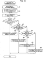
- Fig. 11 is a flow chart illustrating details of a lane mark type determination process in step #11 of Fig. 10 .
- the process described below is performed by the functional units described above that may be implemented by hardware or software or a combination of hardware and software.
- a processing unit (a computer) disposed in the navigation apparatus 1 executes the image recognition program implementing the functional units.
- image recognition process is described below with reference to the flow charts.
- the navigation apparatus 1 first acquires one frame of image information G sensed by the image sensing apparatus 11 via the image information acquisition unit 12 (step #01).
- the image information G includes at least an image of a road surface Ro (see Fig. 4 ) in an area close to the vehicle C.
- the image recognition unit 31 performs the image recognition process to detect a leading end Pb of a lane mark L included in the detection area A ( Figs. 5 to 7 ) defined in each frame Gf of image information G (step #02).
- step #03 If no leading end Pb of a lane mark L is detected in the image recognition process in the detection area A in the present frame Gf (that is, if the answer to step #03 is No), the processing flow returns to step #01 to acquire a next frame of image information G and again perform the image recognition process to detect a leading end Pb of a lane mark L (step #02).
- the image recognition unit 31 In a case where a leading end Pb of a lane mark L is detected in the image recognition process in the detection area A in the present frame Gf (that is, if the answer to step #03 is Yes), the image recognition unit 31 outputs leading end detection information to the distance detection unit 32 (step #04).
- the image information acquisition unit 12 acquires a next frame of image information G (step #05).
- the image recognition unit 31 performs the image recognition process to detect a trailing end Pe of the lane mark L included in the detection area A ( Figs. 5 to 7 ) defined in each frame Gf of image information G (step #06). If no trailing end Pe of the lane mark L is detected in the image recognition process in the detection area A in the present frame Gf (that is, if the answer to step #07 is No), the processing flow returns to step #05 to acquire a next frame of image information G and again perform the image recognition process to detect trailing end Pe of the lane mark L (step #06).
- the image recognition unit 31 In a case where a trailing end Pe of the lane mark L is detected in the image recognition process in the detection area A in the present frame Gf (that is, if the answer to step #07 is Yes), the image recognition unit 31 outputs trailing end detection information to the distance detection unit 32 (step #08).
- the navigation apparatus 1 acquires the vehicle speed information S indicating the current vehicle speed v of the vehicle C via the vehicle position information acquisition unit 16 (step #09). Furthermore, the distance detection unit 32 detects the distance d from the leading end Pb to the trailing end Pe of a segment of the lane mark L (step #10). More specifically, in this step, as described above, the distance detection unit 32 detects the distance d on the basis of the vehicle speed v of the vehicle D and the number of frames N between the frame Gf of the image information G in which the leading end Pb of the lane mark L was detected and the frame Gf of the image information G in which the trailing end Pe of the lane mark L was detected.
- the distance detection unit 32 calculates a travel-per-frame distance U indicating a distance the vehicle C travels per frame of the image information G, and further calculates the product of the travel-per-frame distance U and the number of frames N. The resultant product is employed as the detected distance d. Thereafter, the lane mark type determination unit 33 performs the lane mark type determination process to determine the lane mark type of the lane mark L on the basis of the distance d detected by the distance detection unit 32. Thus, the image recognition process is completed. The details of the lane mark type determination process are described below with reference to the flow chart shown in Fig. 11 .
- the lane mark type determination process is performed by the lane mark type determination unit 33 as follows.
- vehicle position information P is first acquired via the vehicle position information acquisition unit 16 (step #21).
- a determination is made as to a road type of a road on which the vehicle C is running and a region in which the road is located (step #22).
- a pattern of the determination rule R is selected (step #23).
- the lane mark type determination unit 33 selects a pattern of the determination rule R from the three patterns (A) to (C) according to the pattern application table 35.
- step #10 a determination is made as to whether the distance d detected in step #10 is within the distance range corresponding to the lane mark type "wide broken line" defined by the determination rule R selected in step #23 (step #24). If the detected distance d is within the distance range corresponding to the lane mark type "wide broken line” defined by the determination rule R (that is, if the answer to step #24 is Yes), the lane mark type determination unit 33 determines that the type of the lane mark L whose leading end Pb and trailing end Pe were detected by the image recognition unit 31 is "wide broken line” (step #25).
- step #24 a determination is made as to whether the distance d detected in step #10 is within the distance range corresponding to the lane mark type "normal broken line” defined by the determination rule R selected in step #23 (step #26). If the detected distance d is within the distance range corresponding to the lane mark type "normal broken line” defined by the determination rule R (that is, if the answer to step #26 is Yes), the lane mark type determination unit 33 determines that the type of the lane mark L whose leading end Pb and trailing end Pe were detected by the image recognition unit 31 is "normal broken line” (step #27).
- step #10 If the detected distance d is not within the distance range corresponding to the lane mark type "normal broken line” defined by the determination rule R (that is, if the answer to step #26 is No), a determination is made as to whether the distance d detected in step #10 is within the distance range corresponding to the lane mark type "solid line” defined by the determination rule R selected in step #23 (step #28).
- the lane mark type determination unit 33 determines that the type of the lane mark L whose leading end Pb and trailing end Pe (virtual trailing end Pe) were detected by the image recognition unit 31 is "solid line” (step #29).
- the lane mark type determination unit 33 determines that the image whose leading end Pb and trailing end Pe were detected by the image recognition unit 31 is not of a lane mark L but of other road marking or feature (step #30). Thus, the lane mark type determination process is completed.
- the distance detection unit 32 detects the distance d from a leading end Pb to a trailing end Pe of a lane mark L, i.e., the length of a segment of the lane mark L.
- the distance detection unit 32 detects the distance d from a trailing end Pe to a leading end Pb of a lane mark L, i.e., the length of a space between two adjacent segments of the lane mark L.
- the determination rule R defined in the determination rule table 34 and the configuration lane mark type determination unit 33 are different from those according to the first embodiment described above.
- the image recognition apparatus 2 is configured to detect the distance d of a space between adjacent segments of a lane mark L and determine the lane mark type on the basis of the detected distance d.
- the image recognition apparatus 2 according to the present embodiment is advantageous in particular when it is used to detect a lane mark type of a broken-line lane mark L whose space varies depending on the lane mark type.
- the recognition is performed for two types of broken-line lane marks L, i.e., the normal-broken-line lane mark L1 and the wide-broken-line lane mark L2, as with the first embodiment described above.
- the image recognition apparatus 2 according to the present embodiment is similar to that according to the first embodiment, and the image recognition apparatus 2 is disposed in the navigation apparatus 1.
- the explanation will be focused on the difference from the first embodiment.
- the distance detection unit 32 detects the distance from a trailing end Pe to a leading end Pb of a lane mark L. More specifically, the distance detection unit 32 detects the distance d on the basis of the vehicle speed v of the vehicle D and the number of frames N between the frame Gf of the image information G in which the trailing end Pe of the lane mark L is detected and the frame Gf of the image information G in which the leading end Pb of the lane mark L is detected.
- the distance detection unit 32 calculates a travel-per-frame distance U indicating a distance the vehicle C travels per frame of the image information G, and further calculates the product of the travel-per-frame distance U and the number of frames N. The resultant product is employed as the detected distance d.
- the calculation of the travel-per-frame distance U and the number of frames N may be performed in a similar manner to the first embodiment described above.
- the detected distance d calculated by the distance detection unit 32 is substantially equal to the distance from the trailing end Pe to the leading end Pb of the lane mark L as shown in Fig. 4 , and thus the detected distance d is substantially equal to the length of each space between two adjacent segments of the lane mark L.
- the determination rule R described in the determination rule table 34 defines the lower and upper limits of the distance ranges corresponding to the respective lane mark types ("normal broken line” and "wide broken line” in the present embodiment) depending on the segment space of each of the lane mark types. More specifically, the distance range of each lane mark type is determined as follows.
- the distance range of each lane mark type is determined depending on the length of the space between segments of lane marks L of the respective lane mark types, i.e., the normal-broken-line lane mark L1 and the wide-broken-line lane mark L2 used for a particular road type or used in a particular region to which the pattern (A) is applied, such that the length of the segment space of the lane mark of each type falls within the distance range of the lane mark type but the length of the space of any other type does not fall in this distance range.
- the determination rule R is similar to that according to the first embodiment described above in that a plurality of distance ranges are defined for each lane mark type, and more specifically, a plurality of patterns of (three patterns (A), (B), and (C)) of distance ranges are defined for each of the two lane mark types, i.e., "normal broken line” and "wide broken line".
- the lane mark type determination unit 33 determines the type of lane mark L on the basis of the detected distance d indicating the space length detected by the distance detection unit 32 for the lane mark L in accordance with the determination rule R. More specifically, the lane mark type determination unit 33 selects one lane mark type depending on the detected distance d from the plurality of broken line types of lane marks (L1 and L2) including the "normal broken line” and "wide broken line”. More specifically, if the lane mark type determination unit 33 determines that the distance d detected by the distance detection unit 32 is in the range corresponding to the lane mark type "wide broken line", then the lane mark type determination unit 33 determines that the lane mark type is "wide broken line".
- the lane mark type determination unit 33 switches the distance ranges used in the determination of the lane mark type, depending on the road type and/or the region where the vehicle C is currently running.
- the lane mark type determination unit 33 correctly determines the type of the lane mark L whose leading end Pb and trailing end Pe are detected by the image recognition unit 31. Also in the present embodiment, as in the first embodiment described above, the information indicating the lane mark type determined by the lane mark type determination unit 33 is supplied to the running lane determination unit 36 and the navigation processing unit 17 and is used in the determination of the lane in which the vehicle is running or in the supplying of guidance information.
- the distance detection unit 32 detects the distance d from a leading end Pb to a trailing end Pe of a lane mark L, i.e., the length of a segment of the lane mark L.
- the distance detection unit 32 detects the distance d from a trailing end Pe to a leading end Pb of a lane mark L, i.e., the length of a space between two adjacent segments of the lane mark L.
- the present invention is not limited to these embodiments.
- the distance detection unit 32 may detect the distance, as a first distance, from a leading end Pb to a trailing end Pe of a lane mark L, i.e., the length of the segment of the lane mark L and may further detect the distance, as a second distance, from a trailing end Pe to a leading end Pb of the lane mark L, i.e., the length of a space between two adjacent segments of the lane mark L whereby the lane mark type determination unit 33 may determine the lane mark type on the basis of the first and second distances.
- the determination rule R defines a distance range in terms of the first detected distance and a distance range in terms of the second detected distance for each lane mark type. The determination of the lane mark type based on the combination of first and second detected distance may be performed for broken-line lane marks L, while the determination of the lane mark type based on only the first detected distance may be performed for solid-line lane marks L.
- the distance from one of the leading end Pb and the trailing end Pe of a lane mark L to the other is detected as the detected distance d only once, and the lane mark type determination unit 33 determines the lane mark type on the basis of the detected distance d.
- leading end Pb and/or trailing ends Pe are detected periodically a plurality of times.
- the lane mark type determination unit 33 determines that the type of the lane mark is a broken line ("normal broken line” or "wide broken line").
- the height of the detection area A in each frame Gf of image information G is set to a fixed value.
- the present invention is not limited to these embodiments. That is, for example, the vertical height of the detection area A may be varied depending on the speed of the vehicle C. More specifically, the vertical height of the detection area A may be set to be as small as possible depending on the speed of the vehicle C, within a range that allows any portion of a road surface Ro to be captured between detection areas A of two adjacent frames Gf. This allows a reduction in the processing load required to perform the image recognition process. Furthermore, it is possible to reduce the error in the distance from the vehicle C to a leading end Pb or a trailing end Pe of a lane mark L due to uncertainty of the position of the leading end Pb or the trailing end Pe in the detection area A.
- the horizontal width of the detection area A in each frame Gf of image information G is set to be equal to the horizontal width of the frame Gf.
- the present invention is not limited to these embodiments. That is, the horizontal width of the detection area A may be set so as to be a part of the horizontal width of the frame Gf. In this case, preferably, the detection area A may be set such that two lane marks L on respective two sides of the vehicle C are detected in the partial area when the vehicle C runs in the middle of a lane. This allows a further reduction in processing load associated with the image recognition process compared with the case where the horizontal width of the detection area A is set to be equal to the horizontal width of the frame Gf.
- the distance detection unit 32 detects the number of frames N between a frame Gf including a leading end Pb detected for a lane mark L and a frame Gf including a subsequent trailing end Pe detected for the same lane mark L on the basis of the frame numbers of the respective frames Gf described in corresponding leading end detection information and trailing end detection information.
- the method of detecting the number of frames N is not limited to that disclosed above in the embodiments.
- the distance detection unit 32 may start counting the number of frames of image information G acquired by the image information acquisition unit 12, and the distance detection unit 32 may stop the counting of the number frames when a trailing end Pe of the lane mark L is detected by the image recognition unit 31.
- the count obtained in this way indicates the number of frames N between the frame Gf including the leading end Pb detected for the lane mark L and the frame Gf including the subsequent trailing end Pe detected for the same lane mark L.
- the lane mark type determination unit 33 changes the detected distance range defined for each lane mark type as the criterion to determine the lane mark type by determining whether the detected distance is within the defined range.
- the present invention is not limited to these embodiments.
- the lane mark type determination unit 33 may change the detected distance range defined for each lane mark type as the criterion to determine the lane mark type, depending on one of the type of the road on which the vehicle is running and the region where the road is located.
- the pattern application table 35 may define the determination rule R in terms of patterns ((A), (B), and (C)) to be applied to a plurality of respective road types, or the pattern application table 35 may define the determination rule R in terms of patterns ((A), (B), and (C)) to be applied to a plurality of respective regions.
- the same distance ranges defined in the determination rule R may be used regardless of the road type or the region.
- the number of patterns may be 2 or 4 or greater.
- the image recognition apparatus 2 in the navigation apparatus 1 also functions as the running lane determination apparatus.
- the present invention is not limited to these embodiments.
- the present invention may also be applied to various kinds of other apparatuses that use information obtained as a result of the process of acquiring image information including at least an image of a road surface in an area close to a vehicle, and determining the type of a lane mark included in the image information by performing the image recognition process on the acquired image information.
- the image recognition apparatus 2 according to the present invention may be applied to a vehicle drive control apparatus such as a lane keep assist apparatus.
- an image information acquisition unit acquires image information of a plurality of frames of images sensed at regular intervals, each image including a road surface of an area close to a vehicle.
- An image recognition unit performs an image recognition process to detect a leading end and a trailing end of a lane mark included in a detection area defined in each frame of the image information.
- a distance detection unit detects the distance from one of the ends of the lane mark to the other on the basis of the speed of the vehicle and the number of frames between a frame in which one of the ends of the lane mark is detected and a frame in which the other end of the lane mark is detected.
- a lane mark type determination unit determines the lane mark type of the lane mark on the basis of the detected distance.
Landscapes
- Engineering & Computer Science (AREA)
- Physics & Mathematics (AREA)
- General Physics & Mathematics (AREA)
- Multimedia (AREA)
- Theoretical Computer Science (AREA)
- Traffic Control Systems (AREA)
- Image Processing (AREA)
- Navigation (AREA)
- Image Analysis (AREA)
Claims (11)
- Bilderkennungsvorrichtung, miteiner Bildinformationserlangungseinheit (12), die dazu eingerichtet ist, um eine Vielzahl von Frames von Bildinformationen (G), die bei vorbestimmten regelmäßigen Zeitintervallen aufgenommen sind, zu erlangen, wobei jedes Frame zumindest eine Straßenoberfläche (Ro) eines Bereichs in der Umgebung eines Fahrzeugs (C) umfasst,einer Bilderkennungseinheit (31), die dazu eingerichtet ist, um einen Bilderkennungsprozess durchzuführen in einem Erfassungsbereich, der in jedem der erlangten Frames der Bildinformationen definiert ist, um eines aus einem Vorderende (Pb) und einem Hinterende (Pe) einer Spurmarkierung (L) zu erfassen, die in dem Erfassungsbereich eines erlangten Frames der Bildinformationen enthalten ist, und um das andere aus dem Vorderende (Pb) und dem Hinterende (Pe) der Spurmarkierung (L) zu erfassen, die in dem Erfassungsbereich eines nachfolgend erlangten Frames der Bildinformationen enthalten ist,einer Abstandserfassungseinheit (32), die dazu eingerichtet ist, um den Abstand (d) entweder von dem Vorderende der Spurmarkierung zu dem Hinterende der Spurmarkierung, das als erstes nach einer Erfassung des Vorderendes erfasst ist, als einen erfassten Abstand zu erfassen basierend auf der Geschwindigkeit des Fahrzeugs (v) und der Anzahl von Frames (N) zwischen dem Frame, in dem das Vorderende der Spurmarkierung erfasst ist, und dem Frame, in dem das Hinterende der Spurmarkierung, das als erstes nach einer Erfassung des Vorderendes erfasst ist, oder von dem Hinterende der Spurmarkierung zu dem Vorderende der Spurmarkierung, das als erstes nach einer Erfassung des Hinterendes erfasst ist, als einen erfassten Abstand basierend auf der Geschwindigkeit des Fahrzeugs (v) und der Anzahl von Frames (N) zwischen dem Frame, in dem das Hinterende der Spurmarkierung erfasst ist, und dem Frame, in dem das Vorderende der Spurmarkierung, das als erstes nach einer Erfassung des Hinterendes erfasst ist, erfasst ist, undeiner Spurmarkierungstypbestimmungseinheit (33), die dazu eingerichtet ist, um einen Spurmarkierungstyp der Spurmarkierung basierend auf dem erfassten Abstand zu bestimmen,wobei die Abstandserfassungseinheit (32) den erfassten Abstand durch Berechnen des Abstands, den das Fahrzeug für jedes Frame der Bildinformation sich fortbewegt basierend auf der Geschwindigkeit des Fahrzeugs, durch Multiplizieren des Fahrzeugfortbewegungsabstands pro Frame mit der Anzahl von Frames (N), und durch Einsetzen des resultierenden Werts als den erfassten Abstand erzeugt, undwobei der Erfassungsbereich in jedem Frame derart definiert ist, dass ein Ort des Erfassungsbereichs in jedem Frame fest ist und eine Breite des Erfassungsbereichs in der horizontalen Richtung gleich einer Breite des Frames in der horizontalen Richtung ist, und eine vertikale Höhe des Erfassungsbereichs derart eingestellt ist, dass jeder Abschnitt der Straßenoberfläche (Ro) des Bereichs in der Umgebung des Fahrzeugs (C) in zumindest einem Erfassungsbereich auftritt.
- Bilderkennungsvorrichtung nach Anspruch 1, wobei die Spurmarkierungstypbestimmungseinheit (33) den Spurmarkierungstyp als eine unterbrochene Linie bestimmt, wenn der erfasste Abstand sich in einer Spanne von einer vorbestimmten Untergrenze zu einer vorbestimmten Obergrenze befindet.
- Bilderkennungsvorrichtung nach Anspruch 2, wobei die Spurmarkierungstypbestimmungseinheit (33) basierend auf dem erfassten Abstand einen aus einer Vielzahl von Typen von Spurmarkierungen einer unterbrochenen Linie auswählt, die in einem oder beiden aus einer Segmentlänge und einem Segmentzwischenraum verschieden sind, und den Ausgewählten als den Spurmarkierungstyp einsetzt.
- Bilderkennungsvorrichtung nach Anspruch 2 oder 3, wobei abhängig von einem oder beiden aus einem Typ einer Straße, auf der das Fahrzeug fährt, und einer Region, in der sich die Straße befindet, die Spurmarkierungstypbestimmungseinheit (33) die Erfassungsabstandspanne, die für jeden Spurmarkierungstyp definiert ist, ändert, wobei die Spanne ein Kriterium ist, das verwendet ist, um den Spurmarkierungstyp zu bestimmen durch Bestimmung, ob der erfasste Abstand innerhalb der definierten Spanne ist.
- Bilderkennungsvorrichtung nach einem der Ansprüche 2 bis 4, wobei die Spurmarkierungstypbestimmungseinheit (33) den Spurmarkierungstyp nur dann als eine unterbrochene Linie bestimmt, wenn Vorderenden und/oder Hinterenden der Spurmarkierung für eine Vielzahl von Malen mit regelmäßigen Intervallen durch die Bilderkennungseinheit (31) erfasst sind.
- Bilderkennungsvorrichtung nach einem der Ansprüche 1 bis 5, wobei die Spurmarkierungstypbestimmungseinheit (33) den Spurmarkierungstyp als eine durchgezogene Linie bestimmt, wenn der erfasste Abstand der Spurmarkierung von deren Vorderende gleich wie oder größer als ein vorbestimmter Durchgezogene-Linie-Erfassungsschwellenwert ist.
- Bilderkennungsvorrichtung nach einem der Ansprüche 1 bis 6, wobei die Spurmarkierungstypbestimmungseinheit (33) den Spurmarkierungstyp gemäß einer Bestimmungsregel (R) bestimmt, die den erfassten Abstand für jeden Spurmarkierungstyp als eine Bedingung definiert, die für den Spurmarkierungstyp eingehalten werden sollte.
- Bilderkennungsvorrichtung nach Anspruch 7, wobei die Bestimmungsregel (R) eine Vielzahl von Erfassungsabstandsspannen für jeden Spurmarkierungstyp definiert.
- Navigationsvorrichtung, miteiner Bilderkennungsvorrichtung nach einem der Ansprüche 1 bis 8,einer Kartendatenbank (26), bei der Karteninformationen (M) gespeichert sind,einem Anwendungsprogramm (18), das unter Verwendung der Karteninformationen und mit einem durch die Bilderkennungsvorrichtung bestimmten Spurmarkierungstyp verknüpften Informationen betreibbar ist, undeiner Führungsinformationsausgabeeinheit, die dazu eingerichtet ist, um gemäß dem Anwendungsprogramm derart im Betrieb zu sein, um Führungsinformationen auszugeben.
- Fahrspurbestimmungsvorrichtung, miteiner Bilderkennungsvorrichtung nach einem der Ansprüche 1 bis 8, undeiner Fahrspurbestimmungseinheit (36), die dazu eingerichtet ist, um eine Spur zu bestimmen, in der ein Fahrzeug (C) fährt, basierend auf mit einem durch die Bilderkennungsvorrichtung bestimmten Spurmarkierungstyp verknüpften Informationen.
- Bilderkennungsprogramm, das durch einen Computer ausführbar ist, um einen Prozess durchzuführen, miteiner Bildinformationserlangungseinheit (12), die dazu eingerichtet ist, um eine Vielzahl von Frames von Bildinformationen (G), die bei vorbestimmten regelmäßigen Zeitintervallen aufgenommen sind, zu erlangen, wobei jedes Frame zumindest eine Straßenoberfläche (Ro) eines Bereichs in der Umgebung eines Fahrzeugs (C) umfasst,einer Bilderkennungseinheit (31), die dazu eingerichtet ist, um einen Bilderkennungsprozess durchzuführen in einem Erfassungsbereich, der in jedem der erlangten Frames der Bildinformationen definiert ist, um eines aus einem Vorderende (Pb) und einem Hinterende (Pe) einer Spurmarkierung (L) zu erfassen, die in dem Erfassungsbereich eines erlangten Frames der Bildinformationen enthalten ist, und um das andere aus dem Vorderende (Pb) und dem Hinterende (Pe) der Spurmarkierung (L) zu erfassen, die in dem Erfassungsbereich eines nachfolgend erlangten Frames der Bildinformationen enthalten ist,einer Abstandserfassungseinheit (32), die dazu eingerichtet ist, um den Abstand (d) entweder von dem Vorderende der Spurmarkierung zu dem Hinterende der Spurmarkierung, das als erstes nach einer Erfassung des Vorderendes erfasst ist, als einen erfassten Abstand zu erfassen basierend auf der Geschwindigkeit des Fahrzeugs (v) und der Anzahl von Frames (N) zwischen dem Frame, in dem das Vorderende der Spurmarkierung erfasst ist, und dem Frame, in dem das Hinterende der Spurmarkierung, das als erstes nach einer Erfassung des Vorderendes erfasst ist, oder von dem Hinterende der Spurmarkierung zu dem Vorderende der Spurmarkierung, das als erstes nach einer Erfassung des Hinterendes erfasst ist, als einen erfassten Abstand basierend auf der Geschwindigkeit des Fahrzeugs (v) und der Anzahl von Frames (N) zwischen dem Frame, in dem das Hinterende der Spurmarkierung erfasst ist, und dem Frame, in dem das Vorderende der Spurmarkierung, das als erstes nach einer Erfassung des Hinterendes erfasst ist, erfasst ist, undeiner Spurmarkierungstypbestimmungseinheit (33), die dazu eingerichtet ist, um einen Spurmarkierungstyp der Spurmarkierung basierend auf dem erfassten Abstand zu bestimmen,wobei die Abstandserfassungseinheit (32) den erfassten Abstand durch Berechnen des Abstands, den das Fahrzeug für jedes Frame der Bildinformation sich fortbewegt basierend auf der Geschwindigkeit des Fahrzeugs, durch Multiplizieren des Fahrzeugfortbewegungsabstands pro Frame mit der Anzahl von Frames (N), und durch Einsetzen des resultierenden Werts als den erfassten Abstand erzeugt, undwobei der Erfassungsbereich in jedem Frame derart definiert ist, dass ein Ort des Erfassungsbereichs in jedem Frame fest ist und eine Breite des Erfassungsbereichs in der horizontalen Richtung gleich einer Breite des Frames in der horizontalen Richtung ist, und eine vertikale Höhe des Erfassungsbereichs derart eingestellt ist, dass jeder Abschnitt der Straßenoberfläche (Ro) des Bereichs in der Umgebung des Fahrzeugs (C) in zumindest einem Erfassungsbereich auftritt.
Applications Claiming Priority (1)
| Application Number | Priority Date | Filing Date | Title |
|---|---|---|---|
| JP2007308922A JP4950858B2 (ja) | 2007-11-29 | 2007-11-29 | 画像認識装置及び画像認識プログラム |
Publications (3)
| Publication Number | Publication Date |
|---|---|
| EP2065835A2 EP2065835A2 (de) | 2009-06-03 |
| EP2065835A3 EP2065835A3 (de) | 2012-07-18 |
| EP2065835B1 true EP2065835B1 (de) | 2018-05-09 |
Family
ID=40401200
Family Applications (1)
| Application Number | Title | Priority Date | Filing Date |
|---|---|---|---|
| EP08170232.6A Not-in-force EP2065835B1 (de) | 2007-11-29 | 2008-11-28 | Bilderkennungsvorrichtung und Bilderkennungsprogramm |
Country Status (4)
| Country | Link |
|---|---|
| US (1) | US7948397B2 (de) |
| EP (1) | EP2065835B1 (de) |
| JP (1) | JP4950858B2 (de) |
| CN (1) | CN101447019B (de) |
Families Citing this family (48)
| Publication number | Priority date | Publication date | Assignee | Title |
|---|---|---|---|---|
| US8929660B2 (en) * | 2009-05-04 | 2015-01-06 | Tomtom North America, Inc. | Apparatus and method for lane marking analysis |
| WO2010140578A1 (ja) * | 2009-06-02 | 2010-12-09 | 日本電気株式会社 | 画像処理装置、画像処理方法、及び画像処理用プログラム |
| KR101228017B1 (ko) * | 2009-12-09 | 2013-02-01 | 한국전자통신연구원 | 위치 정보 기반 영상 인식 장치 및 방법 |
| JP5482167B2 (ja) * | 2009-12-10 | 2014-04-23 | アイシン・エィ・ダブリュ株式会社 | 車両用走行案内装置、車両用走行案内方法及びコンピュータプログラム |
| CN102201167B (zh) * | 2010-04-07 | 2013-03-06 | 宫宁生 | 基于视频的汽车车道自动识别方法 |
| JP5276637B2 (ja) * | 2010-09-08 | 2013-08-28 | 富士重工業株式会社 | 車線推定装置 |
| WO2012034596A1 (en) * | 2010-09-16 | 2012-03-22 | Tomtom Polska Sp.Z.O.O. | Improvements in or relating to automatic detection of the number of lanes into which a road is divided |
| CN102184535B (zh) * | 2011-04-14 | 2013-08-14 | 西北工业大学 | 一种车辆所在车道边界检测方法 |
| CN103764448B (zh) * | 2011-09-05 | 2016-03-02 | 三菱电机株式会社 | 图像处理装置及图像处理方法 |
| JP5792678B2 (ja) * | 2012-06-01 | 2015-10-14 | 株式会社日本自動車部品総合研究所 | 車線境界線検出装置およびプログラム |
| CN104603841B (zh) * | 2012-08-30 | 2017-10-24 | 本田技研工业株式会社 | 行车线标识识别装置 |
| US8971573B2 (en) * | 2012-09-12 | 2015-03-03 | Xerox Corporation | Video-tracking for video-based speed enforcement |
| DE102014210411A1 (de) * | 2013-09-06 | 2015-03-12 | Robert Bosch Gmbh | Verfahren und Steuer- und Erfassungseinrichtung zum Plausibilisieren einer Falschfahrt eines Kraftfahrzeugs |
| KR101509995B1 (ko) * | 2013-12-03 | 2015-04-07 | 현대자동차주식회사 | Jc 진출입 판단 장치 및 그 방법 |
| EP2918974B1 (de) * | 2014-03-11 | 2019-01-16 | Volvo Car Corporation | Verfahren und System zur Bestimmung der Position eines Fahrzeugs |
| JP2015179368A (ja) * | 2014-03-19 | 2015-10-08 | 株式会社日本自動車部品総合研究所 | 走行区画線認識装置及び走行区画線認識プログラム |
| JP6141788B2 (ja) * | 2014-04-14 | 2017-06-07 | 本田技研工業株式会社 | レーンマーク認識装置 |
| CN106537892B (zh) * | 2014-05-29 | 2021-01-05 | 株式会社尼康 | 摄像装置及车辆 |
| EP3154835A1 (de) * | 2014-06-10 | 2017-04-19 | Mobileye Vision Technologies Ltd. | Hierarchische verfeinerung in fahrbahnmarkierungsnavigation |
| JP6536340B2 (ja) * | 2014-12-01 | 2019-07-03 | 株式会社デンソー | 画像処理装置 |
| JP6344275B2 (ja) * | 2015-03-18 | 2018-06-20 | トヨタ自動車株式会社 | 車両制御装置 |
| CN107850456B (zh) * | 2015-07-27 | 2020-12-01 | 日产自动车株式会社 | 路径引导装置以及路径引导方法 |
| FR3047932B1 (fr) * | 2016-02-19 | 2018-03-16 | Peugeot Citroen Automobiles Sa | Dispositif et procede d'estimation du niveau d'attention d'un conducteur d'un vehicule |
| EP3483022B1 (de) * | 2016-07-05 | 2020-11-04 | Nissan Motor Co., Ltd. | Fahrwegsteuerungsverfahren und fahrwegsteuerungsvorrichtung |
| CN107643086B (zh) * | 2016-07-22 | 2021-04-13 | 北京四维图新科技股份有限公司 | 一种车辆定位方法、装置及系统 |
| JP6835499B2 (ja) * | 2016-07-29 | 2021-02-24 | 株式会社ゼンリン | 制御システム及び制御システムに用いられる地図データのデータ構造 |
| JP6586930B2 (ja) * | 2016-08-04 | 2019-10-09 | トヨタ自動車株式会社 | 車両走行制御装置 |
| MX394154B (es) * | 2016-09-27 | 2025-03-24 | Nissan Motor | Metodo de estimacion de la posicion propia y dispositivo de estimacion de la posicion propia. |
| JP6674365B2 (ja) * | 2016-10-21 | 2020-04-01 | 株式会社Soken | 区画線認識装置 |
| CN106696961B (zh) * | 2016-12-09 | 2018-11-20 | 重庆长安汽车股份有限公司 | 高速公路自动驾驶上下匝道控制系统及方法 |
| JP6817804B2 (ja) * | 2016-12-16 | 2021-01-20 | クラリオン株式会社 | 区画線認識装置 |
| CN110167813B (zh) * | 2017-01-10 | 2022-05-03 | 三菱电机株式会社 | 行驶路径识别装置及行驶路径识别方法 |
| CN106934360A (zh) * | 2017-03-06 | 2017-07-07 | 广州英卓电子科技有限公司 | 一种基于高速图像识别的车辆精确位移测量方法 |
| KR20190012370A (ko) * | 2017-07-27 | 2019-02-11 | 삼성에스디에스 주식회사 | 차선 변경 지원 방법 및 장치 |
| JP7013727B2 (ja) * | 2017-08-25 | 2022-02-01 | 株式会社デンソー | 車両制御装置 |
| JP6710190B2 (ja) * | 2017-09-29 | 2020-06-17 | クラリオン株式会社 | 区画線認識装置 |
| CN108256470A (zh) * | 2018-01-16 | 2018-07-06 | 鹰驾科技(深圳)有限公司 | 一种车道偏移判断方法及汽车 |
| JP6731680B2 (ja) * | 2018-08-23 | 2020-07-29 | 荏原環境プラント株式会社 | 情報処理装置、情報処理プログラム、および情報処理方法 |
| CN109166353B (zh) * | 2018-09-12 | 2021-08-20 | 安徽中科美络信息技术有限公司 | 一种车辆行驶前方复杂路口导向车道检测方法及系统 |
| CN111241894B (zh) * | 2018-11-28 | 2023-06-27 | 海信集团有限公司 | 一种检测车道线的方法及车载设备 |
| US11010617B2 (en) * | 2018-12-12 | 2021-05-18 | Here Global B.V. | Methods and systems for determining roadwork zone extension based on lane marking data |
| CN111750878B (zh) * | 2019-03-28 | 2022-06-24 | 北京魔门塔科技有限公司 | 一种车辆位姿的修正方法和装置 |
| JP7255345B2 (ja) * | 2019-05-13 | 2023-04-11 | スズキ株式会社 | 走行車線認識装置、走行車線認識方法およびプログラム |
| CN116295513B (zh) * | 2019-08-22 | 2025-12-23 | 魔门塔(苏州)科技有限公司 | 一种电子导航地图质量检测方法及装置 |
| CN113157827B (zh) * | 2020-01-22 | 2023-10-10 | 阿里巴巴集团控股有限公司 | 车道类型的生成方法、装置、数据处理设备及存储介质 |
| JP7330911B2 (ja) * | 2020-02-05 | 2023-08-22 | マツダ株式会社 | 車両用制御装置 |
| CN112712708A (zh) * | 2020-12-28 | 2021-04-27 | 上海眼控科技股份有限公司 | 信息检测方法、装置、设备及存储介质 |
| FR3134779A1 (fr) * | 2022-04-25 | 2023-10-27 | Psa Automobiles Sa | Procédé et dispositif de contrôle d’un système d’aide à la conduite de véhicule en fonction d’un type de ligne de marquage au sol déterminé à partir de données caméra et de données dynamiques du véhicule |
Citations (1)
| Publication number | Priority date | Publication date | Assignee | Title |
|---|---|---|---|---|
| JP2005004442A (ja) * | 2003-06-11 | 2005-01-06 | Matsushita Electric Ind Co Ltd | 走行車線判別装置 |
Family Cites Families (7)
| Publication number | Priority date | Publication date | Assignee | Title |
|---|---|---|---|---|
| JP3304687B2 (ja) * | 1995-05-24 | 2002-07-22 | 日産自動車株式会社 | 車両用走行車線認識装置及び障害物検出装置・道路逸脱報知装置 |
| US6978037B1 (en) * | 2000-11-01 | 2005-12-20 | Daimlerchrysler Ag | Process for recognition of lane markers using image data |
| JP3945494B2 (ja) * | 2004-05-11 | 2007-07-18 | トヨタ自動車株式会社 | 走行レーン認識装置 |
| JP3722485B1 (ja) * | 2004-05-19 | 2005-11-30 | 本田技研工業株式会社 | 車両用走行区分線認識装置 |
| DE102005014114A1 (de) * | 2005-03-21 | 2006-10-05 | Valeo Schalter Und Sensoren Gmbh | Spurerkennungssystem und Verfahren |
| JP4659631B2 (ja) * | 2005-04-26 | 2011-03-30 | 富士重工業株式会社 | 車線認識装置 |
| JP4755501B2 (ja) | 2006-01-30 | 2011-08-24 | クラリオン株式会社 | 車線検出装置および車線逸脱警報装置 |
-
2007
- 2007-11-29 JP JP2007308922A patent/JP4950858B2/ja not_active Expired - Fee Related
-
2008
- 2008-11-12 CN CN200810175427.XA patent/CN101447019B/zh not_active Expired - Fee Related
- 2008-11-28 US US12/292,887 patent/US7948397B2/en not_active Expired - Fee Related
- 2008-11-28 EP EP08170232.6A patent/EP2065835B1/de not_active Not-in-force
Patent Citations (1)
| Publication number | Priority date | Publication date | Assignee | Title |
|---|---|---|---|---|
| JP2005004442A (ja) * | 2003-06-11 | 2005-01-06 | Matsushita Electric Ind Co Ltd | 走行車線判別装置 |
Also Published As
| Publication number | Publication date |
|---|---|
| US7948397B2 (en) | 2011-05-24 |
| JP2009134429A (ja) | 2009-06-18 |
| CN101447019B (zh) | 2014-04-23 |
| EP2065835A3 (de) | 2012-07-18 |
| CN101447019A (zh) | 2009-06-03 |
| JP4950858B2 (ja) | 2012-06-13 |
| US20090174577A1 (en) | 2009-07-09 |
| EP2065835A2 (de) | 2009-06-03 |
Similar Documents
| Publication | Publication Date | Title |
|---|---|---|
| EP2065835B1 (de) | Bilderkennungsvorrichtung und Bilderkennungsprogramm | |
| US8346473B2 (en) | Lane determining device, lane determining method and navigation apparatus using the same | |
| EP1991973B1 (de) | Bildverarbeitungssystem und verfahren | |
| EP2113746B1 (de) | Vorrichtung zum Sammeln von Merkmalsinformationen und Programm zum Sammeln von Merkmalsinformationen und Vorrichtung zur Erkennung einer Fahrzeugposition und Navigationsvorrichtung | |
| CN101246010B (zh) | 车道判定装置以及车道判定方法 | |
| US8155873B2 (en) | Vehicle-position-recognition apparatuses, methods, and programs | |
| EP2065679B1 (de) | Navigationsvorrichtung, Navigationsverfahren und Navigationsprogramm | |
| US8175800B2 (en) | Route guidance system and route guidance method | |
| EP2009400A2 (de) | Vorrichtung zur Fahrzeugpositionserkennung, Navigationsvorrichtung, Verfahren zur Fahrzeugpositionserkennung | |
| JP2006208223A (ja) | 車両位置認識装置及び車両位置認識方法 | |
| JPH09152348A (ja) | カーナビゲーション装置 | |
| JP2018040693A (ja) | 運転支援装置、運転支援方法 | |
| JP4953012B2 (ja) | 画像認識装置と画像認識装置のためのプログラム、及びこれを用いたナビゲーション装置とナビゲーション装置のためのプログラム | |
| JP5141969B2 (ja) | 画像認識装置及び画像認識プログラム、並びにそれを用いた地点情報収集装置及びナビゲーション装置 | |
| JP4775658B2 (ja) | 地物認識装置・自車位置認識装置・ナビゲーション装置・地物認識方法 | |
| JP5071737B2 (ja) | レーン判定装置及びレーン判定プログラム、並びにそれを用いたナビゲーション装置 | |
| JP2009058430A (ja) | ナビゲーション装置及びナビゲーションプログラム | |
| JP2007241470A (ja) | 車両用地図データ更新装置 | |
| JP4943246B2 (ja) | レーン判定装置及びレーン判定プログラム、並びにそれを用いたナビゲーション装置 | |
| JP2012208877A (ja) | 車両情報取得装置、車両情報取得方法及びプログラム |
Legal Events
| Date | Code | Title | Description |
|---|---|---|---|
| PUAI | Public reference made under article 153(3) epc to a published international application that has entered the european phase |
Free format text: ORIGINAL CODE: 0009012 |
|
| AK | Designated contracting states |
Kind code of ref document: A2 Designated state(s): AT BE BG CH CY CZ DE DK EE ES FI FR GB GR HR HU IE IS IT LI LT LU LV MC MT NL NO PL PT RO SE SI SK TR |
|
| AX | Request for extension of the european patent |
Extension state: AL BA MK RS |
|
| PUAL | Search report despatched |
Free format text: ORIGINAL CODE: 0009013 |
|
| RIC1 | Information provided on ipc code assigned before grant |
Ipc: G06K 9/00 20060101AFI20120515BHEP |
|
| AK | Designated contracting states |
Kind code of ref document: A3 Designated state(s): AT BE BG CH CY CZ DE DK EE ES FI FR GB GR HR HU IE IS IT LI LT LU LV MC MT NL NO PL PT RO SE SI SK TR |
|
| AX | Request for extension of the european patent |
Extension state: AL BA MK RS |
|
| 17P | Request for examination filed |
Effective date: 20130110 |
|
| AKX | Designation fees paid |
Designated state(s): AT BE BG CH CY CZ DE DK EE ES FI FR GB GR HR HU IE IS IT LI LT LU LV MC MT NL NO PL PT RO SE SI SK TR |
|
| 17Q | First examination report despatched |
Effective date: 20131128 |
|
| GRAP | Despatch of communication of intention to grant a patent |
Free format text: ORIGINAL CODE: EPIDOSNIGR1 |
|
| INTG | Intention to grant announced |
Effective date: 20171115 |
|
| GRAS | Grant fee paid |
Free format text: ORIGINAL CODE: EPIDOSNIGR3 |
|
| GRAA | (expected) grant |
Free format text: ORIGINAL CODE: 0009210 |
|
| AK | Designated contracting states |
Kind code of ref document: B1 Designated state(s): AT BE BG CH CY CZ DE DK EE ES FI FR GB GR HR HU IE IS IT LI LT LU LV MC MT NL NO PL PT RO SE SI SK TR |
|
| REG | Reference to a national code |
Ref country code: GB Ref legal event code: FG4D |
|
| REG | Reference to a national code |
Ref country code: CH Ref legal event code: EP Ref country code: AT Ref legal event code: REF Ref document number: 998214 Country of ref document: AT Kind code of ref document: T Effective date: 20180515 |
|
| REG | Reference to a national code |
Ref country code: DE Ref legal event code: R096 Ref document number: 602008055166 Country of ref document: DE Ref country code: IE Ref legal event code: FG4D |
|
| REG | Reference to a national code |
Ref country code: NL Ref legal event code: MP Effective date: 20180509 |
|
| REG | Reference to a national code |
Ref country code: LT Ref legal event code: MG4D |
|
| REG | Reference to a national code |
Ref country code: FR Ref legal event code: PLFP Year of fee payment: 11 |
|
| PG25 | Lapsed in a contracting state [announced via postgrant information from national office to epo] |
Ref country code: FI Free format text: LAPSE BECAUSE OF FAILURE TO SUBMIT A TRANSLATION OF THE DESCRIPTION OR TO PAY THE FEE WITHIN THE PRESCRIBED TIME-LIMIT Effective date: 20180509 Ref country code: LT Free format text: LAPSE BECAUSE OF FAILURE TO SUBMIT A TRANSLATION OF THE DESCRIPTION OR TO PAY THE FEE WITHIN THE PRESCRIBED TIME-LIMIT Effective date: 20180509 Ref country code: BG Free format text: LAPSE BECAUSE OF FAILURE TO SUBMIT A TRANSLATION OF THE DESCRIPTION OR TO PAY THE FEE WITHIN THE PRESCRIBED TIME-LIMIT Effective date: 20180809 Ref country code: SE Free format text: LAPSE BECAUSE OF FAILURE TO SUBMIT A TRANSLATION OF THE DESCRIPTION OR TO PAY THE FEE WITHIN THE PRESCRIBED TIME-LIMIT Effective date: 20180509 Ref country code: NO Free format text: LAPSE BECAUSE OF FAILURE TO SUBMIT A TRANSLATION OF THE DESCRIPTION OR TO PAY THE FEE WITHIN THE PRESCRIBED TIME-LIMIT Effective date: 20180809 Ref country code: ES Free format text: LAPSE BECAUSE OF FAILURE TO SUBMIT A TRANSLATION OF THE DESCRIPTION OR TO PAY THE FEE WITHIN THE PRESCRIBED TIME-LIMIT Effective date: 20180509 |
|
| PG25 | Lapsed in a contracting state [announced via postgrant information from national office to epo] |
Ref country code: GR Free format text: LAPSE BECAUSE OF FAILURE TO SUBMIT A TRANSLATION OF THE DESCRIPTION OR TO PAY THE FEE WITHIN THE PRESCRIBED TIME-LIMIT Effective date: 20180810 Ref country code: NL Free format text: LAPSE BECAUSE OF FAILURE TO SUBMIT A TRANSLATION OF THE DESCRIPTION OR TO PAY THE FEE WITHIN THE PRESCRIBED TIME-LIMIT Effective date: 20180509 Ref country code: HR Free format text: LAPSE BECAUSE OF FAILURE TO SUBMIT A TRANSLATION OF THE DESCRIPTION OR TO PAY THE FEE WITHIN THE PRESCRIBED TIME-LIMIT Effective date: 20180509 Ref country code: LV Free format text: LAPSE BECAUSE OF FAILURE TO SUBMIT A TRANSLATION OF THE DESCRIPTION OR TO PAY THE FEE WITHIN THE PRESCRIBED TIME-LIMIT Effective date: 20180509 |
|
| REG | Reference to a national code |
Ref country code: AT Ref legal event code: MK05 Ref document number: 998214 Country of ref document: AT Kind code of ref document: T Effective date: 20180509 |
|
| PG25 | Lapsed in a contracting state [announced via postgrant information from national office to epo] |
Ref country code: AT Free format text: LAPSE BECAUSE OF FAILURE TO SUBMIT A TRANSLATION OF THE DESCRIPTION OR TO PAY THE FEE WITHIN THE PRESCRIBED TIME-LIMIT Effective date: 20180509 Ref country code: DK Free format text: LAPSE BECAUSE OF FAILURE TO SUBMIT A TRANSLATION OF THE DESCRIPTION OR TO PAY THE FEE WITHIN THE PRESCRIBED TIME-LIMIT Effective date: 20180509 Ref country code: EE Free format text: LAPSE BECAUSE OF FAILURE TO SUBMIT A TRANSLATION OF THE DESCRIPTION OR TO PAY THE FEE WITHIN THE PRESCRIBED TIME-LIMIT Effective date: 20180509 Ref country code: CZ Free format text: LAPSE BECAUSE OF FAILURE TO SUBMIT A TRANSLATION OF THE DESCRIPTION OR TO PAY THE FEE WITHIN THE PRESCRIBED TIME-LIMIT Effective date: 20180509 Ref country code: SK Free format text: LAPSE BECAUSE OF FAILURE TO SUBMIT A TRANSLATION OF THE DESCRIPTION OR TO PAY THE FEE WITHIN THE PRESCRIBED TIME-LIMIT Effective date: 20180509 Ref country code: RO Free format text: LAPSE BECAUSE OF FAILURE TO SUBMIT A TRANSLATION OF THE DESCRIPTION OR TO PAY THE FEE WITHIN THE PRESCRIBED TIME-LIMIT Effective date: 20180509 Ref country code: PL Free format text: LAPSE BECAUSE OF FAILURE TO SUBMIT A TRANSLATION OF THE DESCRIPTION OR TO PAY THE FEE WITHIN THE PRESCRIBED TIME-LIMIT Effective date: 20180509 |
|
| REG | Reference to a national code |
Ref country code: DE Ref legal event code: R097 Ref document number: 602008055166 Country of ref document: DE |
|
| PG25 | Lapsed in a contracting state [announced via postgrant information from national office to epo] |
Ref country code: IT Free format text: LAPSE BECAUSE OF FAILURE TO SUBMIT A TRANSLATION OF THE DESCRIPTION OR TO PAY THE FEE WITHIN THE PRESCRIBED TIME-LIMIT Effective date: 20180509 |
|
| PLBE | No opposition filed within time limit |
Free format text: ORIGINAL CODE: 0009261 |
|
| STAA | Information on the status of an ep patent application or granted ep patent |
Free format text: STATUS: NO OPPOSITION FILED WITHIN TIME LIMIT |
|
| 26N | No opposition filed |
Effective date: 20190212 |
|
| PG25 | Lapsed in a contracting state [announced via postgrant information from national office to epo] |
Ref country code: SI Free format text: LAPSE BECAUSE OF FAILURE TO SUBMIT A TRANSLATION OF THE DESCRIPTION OR TO PAY THE FEE WITHIN THE PRESCRIBED TIME-LIMIT Effective date: 20180509 |
|
| REG | Reference to a national code |
Ref country code: CH Ref legal event code: PL |
|
| PG25 | Lapsed in a contracting state [announced via postgrant information from national office to epo] |
Ref country code: LU Free format text: LAPSE BECAUSE OF NON-PAYMENT OF DUE FEES Effective date: 20181128 Ref country code: MC Free format text: LAPSE BECAUSE OF FAILURE TO SUBMIT A TRANSLATION OF THE DESCRIPTION OR TO PAY THE FEE WITHIN THE PRESCRIBED TIME-LIMIT Effective date: 20180509 |
|
| REG | Reference to a national code |
Ref country code: BE Ref legal event code: MM Effective date: 20181130 |
|
| REG | Reference to a national code |
Ref country code: IE Ref legal event code: MM4A |
|
| PG25 | Lapsed in a contracting state [announced via postgrant information from national office to epo] |
Ref country code: LI Free format text: LAPSE BECAUSE OF NON-PAYMENT OF DUE FEES Effective date: 20181130 Ref country code: CH Free format text: LAPSE BECAUSE OF NON-PAYMENT OF DUE FEES Effective date: 20181130 |
|
| PG25 | Lapsed in a contracting state [announced via postgrant information from national office to epo] |
Ref country code: IE Free format text: LAPSE BECAUSE OF NON-PAYMENT OF DUE FEES Effective date: 20181128 |
|
| PG25 | Lapsed in a contracting state [announced via postgrant information from national office to epo] |
Ref country code: BE Free format text: LAPSE BECAUSE OF NON-PAYMENT OF DUE FEES Effective date: 20181130 |
|
| PG25 | Lapsed in a contracting state [announced via postgrant information from national office to epo] |
Ref country code: MT Free format text: LAPSE BECAUSE OF NON-PAYMENT OF DUE FEES Effective date: 20181128 |
|
| PGFP | Annual fee paid to national office [announced via postgrant information from national office to epo] |
Ref country code: DE Payment date: 20191112 Year of fee payment: 12 |
|
| PGFP | Annual fee paid to national office [announced via postgrant information from national office to epo] |
Ref country code: FR Payment date: 20191014 Year of fee payment: 12 |
|
| PG25 | Lapsed in a contracting state [announced via postgrant information from national office to epo] |
Ref country code: TR Free format text: LAPSE BECAUSE OF FAILURE TO SUBMIT A TRANSLATION OF THE DESCRIPTION OR TO PAY THE FEE WITHIN THE PRESCRIBED TIME-LIMIT Effective date: 20180509 |
|
| PGFP | Annual fee paid to national office [announced via postgrant information from national office to epo] |
Ref country code: GB Payment date: 20191129 Year of fee payment: 12 |
|
| PG25 | Lapsed in a contracting state [announced via postgrant information from national office to epo] |
Ref country code: PT Free format text: LAPSE BECAUSE OF FAILURE TO SUBMIT A TRANSLATION OF THE DESCRIPTION OR TO PAY THE FEE WITHIN THE PRESCRIBED TIME-LIMIT Effective date: 20180509 |
|
| PG25 | Lapsed in a contracting state [announced via postgrant information from national office to epo] |
Ref country code: CY Free format text: LAPSE BECAUSE OF FAILURE TO SUBMIT A TRANSLATION OF THE DESCRIPTION OR TO PAY THE FEE WITHIN THE PRESCRIBED TIME-LIMIT Effective date: 20180509 Ref country code: HU Free format text: LAPSE BECAUSE OF FAILURE TO SUBMIT A TRANSLATION OF THE DESCRIPTION OR TO PAY THE FEE WITHIN THE PRESCRIBED TIME-LIMIT; INVALID AB INITIO Effective date: 20081128 |
|
| PG25 | Lapsed in a contracting state [announced via postgrant information from national office to epo] |
Ref country code: IS Free format text: LAPSE BECAUSE OF FAILURE TO SUBMIT A TRANSLATION OF THE DESCRIPTION OR TO PAY THE FEE WITHIN THE PRESCRIBED TIME-LIMIT Effective date: 20180909 |
|
| REG | Reference to a national code |
Ref country code: DE Ref legal event code: R119 Ref document number: 602008055166 Country of ref document: DE |
|
| GBPC | Gb: european patent ceased through non-payment of renewal fee |
Effective date: 20201128 |
|
| PG25 | Lapsed in a contracting state [announced via postgrant information from national office to epo] |
Ref country code: FR Free format text: LAPSE BECAUSE OF NON-PAYMENT OF DUE FEES Effective date: 20201130 |
|
| PG25 | Lapsed in a contracting state [announced via postgrant information from national office to epo] |
Ref country code: DE Free format text: LAPSE BECAUSE OF NON-PAYMENT OF DUE FEES Effective date: 20210601 Ref country code: GB Free format text: LAPSE BECAUSE OF NON-PAYMENT OF DUE FEES Effective date: 20201128 |