EP1991899B9 - Mikroskopiesystem mit einem schwenkbaren spiegelpaar zur kompensation eines objektversatzes - Google Patents
Mikroskopiesystem mit einem schwenkbaren spiegelpaar zur kompensation eines objektversatzes Download PDFInfo
- Publication number
- EP1991899B9 EP1991899B9 EP07723118.1A EP07723118A EP1991899B9 EP 1991899 B9 EP1991899 B9 EP 1991899B9 EP 07723118 A EP07723118 A EP 07723118A EP 1991899 B9 EP1991899 B9 EP 1991899B9
- Authority
- EP
- European Patent Office
- Prior art keywords
- imaging
- mirror face
- offset
- object plane
- microscopy system
- Prior art date
- Legal status (The legal status is an assumption and is not a legal conclusion. Google has not performed a legal analysis and makes no representation as to the accuracy of the status listed.)
- Active
Links
- 238000000386 microscopy Methods 0.000 title claims description 82
- 238000003384 imaging method Methods 0.000 claims description 309
- 230000003287 optical effect Effects 0.000 claims description 103
- 238000005286 illumination Methods 0.000 claims description 48
- 238000006073 displacement reaction Methods 0.000 claims description 33
- 238000000034 method Methods 0.000 claims description 8
- 230000004424 eye movement Effects 0.000 claims description 3
- 230000004886 head movement Effects 0.000 claims description 3
- 238000012545 processing Methods 0.000 claims description 3
- 230000001419 dependent effect Effects 0.000 claims 11
- 239000003550 marker Substances 0.000 description 13
- 230000004044 response Effects 0.000 description 8
- 230000008859 change Effects 0.000 description 4
- 238000010276 construction Methods 0.000 description 4
- 230000000694 effects Effects 0.000 description 4
- 230000000737 periodic effect Effects 0.000 description 4
- 239000013598 vector Substances 0.000 description 4
- 230000001133 acceleration Effects 0.000 description 3
- 230000008901 benefit Effects 0.000 description 3
- 238000010586 diagram Methods 0.000 description 3
- 230000005855 radiation Effects 0.000 description 3
- 230000006641 stabilisation Effects 0.000 description 3
- 238000011105 stabilization Methods 0.000 description 3
- 230000000007 visual effect Effects 0.000 description 3
- 230000000712 assembly Effects 0.000 description 2
- 238000000429 assembly Methods 0.000 description 2
- 238000003331 infrared imaging Methods 0.000 description 2
- 238000013507 mapping Methods 0.000 description 2
- 230000029058 respiratory gaseous exchange Effects 0.000 description 2
- 206010028980 Neoplasm Diseases 0.000 description 1
- 230000003044 adaptive effect Effects 0.000 description 1
- 230000005540 biological transmission Effects 0.000 description 1
- 201000011510 cancer Diseases 0.000 description 1
- 238000006243 chemical reaction Methods 0.000 description 1
- 238000012937 correction Methods 0.000 description 1
- 230000008878 coupling Effects 0.000 description 1
- 238000010168 coupling process Methods 0.000 description 1
- 238000005859 coupling reaction Methods 0.000 description 1
- 238000011161 development Methods 0.000 description 1
- 230000018109 developmental process Effects 0.000 description 1
- 238000005516 engineering process Methods 0.000 description 1
- 238000005259 measurement Methods 0.000 description 1
- 230000007246 mechanism Effects 0.000 description 1
- 210000000056 organ Anatomy 0.000 description 1
- 210000001747 pupil Anatomy 0.000 description 1
- 238000000926 separation method Methods 0.000 description 1
- 239000007787 solid Substances 0.000 description 1
- 238000002560 therapeutic procedure Methods 0.000 description 1
- 238000013519 translation Methods 0.000 description 1
Images


Classifications
-
- G—PHYSICS
- G02—OPTICS
- G02B—OPTICAL ELEMENTS, SYSTEMS OR APPARATUS
- G02B26/00—Optical devices or arrangements for the control of light using movable or deformable optical elements
- G02B26/08—Optical devices or arrangements for the control of light using movable or deformable optical elements for controlling the direction of light
- G02B26/0816—Optical devices or arrangements for the control of light using movable or deformable optical elements for controlling the direction of light by means of one or more reflecting elements
-
- A—HUMAN NECESSITIES
- A61—MEDICAL OR VETERINARY SCIENCE; HYGIENE
- A61B—DIAGNOSIS; SURGERY; IDENTIFICATION
- A61B90/00—Instruments, implements or accessories specially adapted for surgery or diagnosis and not covered by any of the groups A61B1/00 - A61B50/00, e.g. for luxation treatment or for protecting wound edges
- A61B90/36—Image-producing devices or illumination devices not otherwise provided for
-
- G—PHYSICS
- G02—OPTICS
- G02B—OPTICAL ELEMENTS, SYSTEMS OR APPARATUS
- G02B21/00—Microscopes
- G02B21/0004—Microscopes specially adapted for specific applications
- G02B21/0012—Surgical microscopes
-
- G—PHYSICS
- G02—OPTICS
- G02B—OPTICAL ELEMENTS, SYSTEMS OR APPARATUS
- G02B21/00—Microscopes
- G02B21/18—Arrangements with more than one light path, e.g. for comparing two specimens
- G02B21/20—Binocular arrangements
- G02B21/22—Stereoscopic arrangements
-
- A—HUMAN NECESSITIES
- A61—MEDICAL OR VETERINARY SCIENCE; HYGIENE
- A61B—DIAGNOSIS; SURGERY; IDENTIFICATION
- A61B90/00—Instruments, implements or accessories specially adapted for surgery or diagnosis and not covered by any of the groups A61B1/00 - A61B50/00, e.g. for luxation treatment or for protecting wound edges
- A61B90/20—Surgical microscopes characterised by non-optical aspects
-
- G—PHYSICS
- G02—OPTICS
- G02B—OPTICAL ELEMENTS, SYSTEMS OR APPARATUS
- G02B27/00—Optical systems or apparatus not provided for by any of the groups G02B1/00 - G02B26/00, G02B30/00
- G02B27/64—Imaging systems using optical elements for stabilisation of the lateral and angular position of the image
- G02B27/642—Optical derotators, i.e. systems for compensating for image rotation, e.g. using rotating prisms, mirrors
Definitions
- the present invention relates to a microscopy system for imaging an object that can be arranged in an object plane of the microscopy system.
- a vibration-proof microscope is out of the DE 101 33 671 A1 known.
- the microscope comprises an optical microscope system which generates an object image in a field of predetermined format, a first sensor for measuring the inclination of the entire microscope system, a second sensor for measuring the movement of the entire microscope system, a deflection device for deflecting object light passing through the microscope system into any one Direction and at any angle, and a control unit for adjusting the deflection and the deflection angle of the object light with the deflection device depending on the measurements of the first sensor and the second sensor, so that the image remains stationary despite a tilt or movement of the microscope system.
- the microscopy system comprises at least one imaging system which provides at least one imaging beam path for imaging a finite (i.e., non-punctiform) imaging field of the object plane and a displacement device configured to translate the imaging field of the imaging system in the object plane.
- microscopy systems are used, for example, in medical technology as surgical microscopes to observe an object arranged in an object plane.
- the surgical microscope is usually carried by a stand attached to a ceiling or standing on the ground tripod.
- the tripod serves as a shifter to allow positioning of the surgical microscope over a viewed object.
- the tripod usually allows a translational displacement of the imaging system with up to three degrees of freedom (forward / backward, left / right, up / down) and usually a rotational movement of the surgical microscope with at least one degree of freedom (pivoting relative to the horizontal).
- tripods are relatively expensive, since they have on the one hand in the locked state a great stability and freedom from vibration and at the same time must be easily operable.
- the tripod must be made sufficiently solid, and the surgical microscope worn by him must be balanced by springs or counterweights in any possible position of the surgical microscope.
- positioning must be possible with high accuracy since an imaging field (area of the object plane imaged by an imaging system of the surgical microscope) of the Surgical microscope is very small especially at high magnification.
- this displacement device has the disadvantage that it is technically complex and, due to its own weight, makes a comparatively more elaborate and more stable tripod necessary. Furthermore, an acceleration of the inertial mass of the surgical microscope is still required for a displacement of the surgical microscope. The inert mass of the Surgical microscope prevents for a quick shift. On the other hand there is a risk that vibrations are generated and transmitted to the tripod with a rapid positive or negative acceleration of the inertial mass of the surgical microscope. In addition, direct visual observation after a surgical microscope shift requires that the user at least slightly adjust his working position.
- the document WO 2006/081031 A2 discloses an optical adaptive scanning microscope ASOM.
- at least one objective lens is arranged between the object and a pivotable mirror, with different regions of the object plane being scanned in succession as a result of the pivoting of the mirror.
- the overall picture is obtained from a plurality of such samples.
- the document GB 2 149 045 A teaches placing a laser beam at a desired position within an imaging field by means of a two-axis pivoting mirror and displacing the laser beam within the imaging field. A shift of the image field itself is not revealed.
- the document relates in particular to the mechanism for a manual pivoting of the mirror.
- the imaging system provides at least one imaging beam path for imaging an imaging field of the object plane.
- imaging field is understood to mean the finite (ie non-point-shaped) region of the object plane which can be imaged at a point in time by the at least one imaging beam path of the imaging system.
- the imaging field is often referred to in the art as an object field.
- the offset device is designed to be the imaging field of the Relocate imaging system in the object plane translational.
- the controller is designed to determine a desired offset of the imaging field in the object plane and to control the displacement device accordingly.
- the offset device has a first mirror surface arranged along the at least one imaging beam path for deflecting the at least one imaging beam path, which first mirror surface can be pivoted as a function of the offset determined by the control.
- a desired offset of the imaging field of the object plane relative to the object plane determined by the control is achieved by pivoting a first mirror surface deflecting the at least one imaging beam path of the imaging system.
- mirror surface in this document generally refers to the reflection surface of an optical deflection element.
- the mirror surface for example, be free or pivotable about one or more predetermined different pivot axes.
- the pivot axes can optionally be outside or inside the mirror surface.
- the mirror surface and the pivot axes can be located either in the same or in different planes.
- two mutually orthogonal pivot axes are provided, which intersect in a region of the mirror surface on which an optical axis of an incident on the mirror surface imaging beam path impinges on the mirror surface. This area can be in the middle of the mirror surface.
- the swivel axes are imaginary axes. This means that the mirror surface is rotated around these imaginary axes, and does not mean that a shaft, such as a rod or rod, must be installed.
- the offset of the imaging field can also be effected by rotating the mirror surface about an axis of rotation which is substantially parallel to an optical axis of at least one of the optical system (in particular optical lenses) of the imaging system Imaging system is aligned on the mirror surface incident imaging beam path.
- a rotation axis which is aligned substantially parallel to the optical axis, that the respectively spanned by the rotation axis or the optical axis and a common normal planes at an angle less than 20 °, preferably less than 5 ° and more preferably less than 2 ° cut.
- the axis of rotation and the optical axis can also coincide.
- the mirror surface can also be rotated about a rotation axis which encloses a non-zero angle with a normal to the mirror surface.
- a rotation of the mirror surface simultaneously causes a pivoting of the mirror surface relative to the optical axis of the at least one imaging beam path incident on the mirror surface by the imaging system, which results in the offset of the imaging field in the object plane.
- a pivoting of a mirror surface is possible with high accuracy. Since only the inertial mass of a deflection element providing the mirror surface (such as, but not limited to, an optical mirror or prism) and any existing drive and / or transmission, but not the inert mass of the entire imaging system has to be accelerated, even small, fast and in particular periodic displacements of the image field in a particularly simple and reliable manner possible. Due to the small inertial mass to be accelerated, the offset device works almost vibration-free even with strong accelerations.
- the offset device may further comprise a second mirror surface arranged along the at least one imaging beam path for deflecting the at least one imaging beam path, which second mirror surface is pivotable as a function of the offset determined by the control. Then, the first mirror surface may be pivotable about a first pivot axis and the second mirror surface about a second pivot axis, which second pivot axis is different from the first pivot axis.
- the displacement of the imaging field can also be effected jointly by pivoting two or even more mirror surfaces, which deflect the at least one imaging beam path in succession. This can bring advantages, since a pivoting of a mirror surface about a single given axis is often easier and with greater accuracy possible, as a free pivoting of a mirror surface.
- the first pivot axis with an initial deflection plane which is spanned by an incident on the first mirror surface and incident from the first mirror surface optical axis of the at least one imaging beam path, include an angle of substantially 90 °.
- the optical axis of optical elements (in particular optical lenses) of the imaging system is fixed.
- the second pivot axis with an second deflection plane which is spanned by the incident on the second mirror surface and incident from the second mirror surface optical axis of the at least one imaging beam path, an angle of substantially 90 ° and at the same time be arranged substantially parallel to the first deflection plane.
- substantially 90 ° in this application means a deviation of 90 ° by at most 5 ° and preferably at most 2 ° and particularly preferably at most 1 °.
- a pivot axis which is essentially parallel to a deflection plane is understood to mean that the pivot axis is parallel to the deflection plane or that the pivot axis intersects the deflection plane and thereby forms an angle of less than 5 ° and preferably less than 2 with the deflection plane ° includes. Further, the pivot axis and the deflection plane may alternatively coincide.
- the first and second pivot axes respectively extend in a region in which the optical axis incident on the respective first and second mirror surfaces impinges on the respective mirror surface. This area can lie in the middle of the respectively associated first and second mirror surface.
- This relationship of the first and second pivot axis relative to the at least one imaging beam path or relative to each other has the advantage that a pivoting of the first and second mirror surface about the pivot axes in addition to the displacement of the imaging field relative to the object plane no or only a negligible rotation of the imaging system causes generated imaging of the imaging field. Further, such a translation of the imaging field in the object plane in two directions, which also form an angle of substantially 90 ° with each other, allows.
- the microscopy system may further comprise a compensation device, which causes a rotation of the imaging field generated by the imaging system.
- the controller controls the compensation device as a function of a pivoting of the first and / or second mirror surface such that a possibly caused by a pivoting of the mirror surfaces Rotation of the image system provided by the mapping of the imaging field is canceled by a caused by the compensation device rotation of the image again.
- the imaging system can have at least one camera arranged in the at least one imaging beam path for generating image data
- the compensation device can be connected to the at least one camera.
- the compensation device can then effect a rotation of the image data generated by the at least one camera by electronic image processing in order to compensate in a particularly simple manner for a rotation of the image of the imaging field provided by the imaging system as a result of a pivoting of the mirror surfaces.
- the compensation device may have at least one prism arrangement arranged in the at least one imaging beam path and adjustable by the control.
- the prism arrangement is preferably designed to effect an image rotation about the optical axis of the imaging system defined optical axis as a rotation axis in a rotation of the prism.
- the offset device has at least one pair of first and second mirror surfaces arranged along the at least one imaging beam path for deflecting the at least one imaging beam path.
- the at least one pair of imaging beam paths is successively reflected at the first and the second mirror surface.
- first mirror surface is pivotable about a first pivot axis, which first pivot axis with a first deflection plane, which is spanned by an incident on the first mirror surface and incident from the first mirror surface optical axis of the at least one imaging beam path, an angle of substantially 90 °.
- the optical axis is defined by optical elements (in particular optical lenses) of the imaging system.
- the second mirror surface is pivotable about a second pivot axis, which second pivot axis with an second deflection plane, which is spanned by the incident on the second mirror surface and incident from the second mirror surface optical axis of the at least one imaging beam path, forms an angle of substantially 90 ° ,
- the second pivot axis is arranged substantially parallel to the first deflection plane. In this case, the second pivot axis can also lie in the first deflection plane.
- first and / or second mirror surface By pivoting the first and / or second mirror surface about the first and / or second pivot axis, a translational displacement of the imaging field in the object plane in two directions, which together form an angle of substantially 90 °, can be effected.
- the said orientation of the first and second pivot axes relative to the at least one imaging beam path results in pivoting of the mirror surfaces causing no or only negligible rotation of the image of the imaging field generated by the imaging system.
- the microscopy system may further include a controller configured to determine a desired offset of the imaging field in the object plane and to pivot the first and second mirror surfaces about the respective first and second pivot axes, respectively, in response to the determined offset ,
- the imaging system can have at least one camera arranged in the at least one imaging beam path for generating image data
- the controller can be connected to the at least one camera and be further configured to automatically detect the position of a marker in the image data and the first and / or second drive automatically depending on the detected position of the marker to control.
- the marker may be, for example, a separate element arranged in the object plane (eg a characteristically formed sticker) or else a characteristic element of the object itself (such as a surgical element depicted in the image data) Instrument or a particular body part of a patient such as a tooth or organ).
- the controller is designed to automatically control the first and / or second drive in such a way that the position of the marker in the image data remains substantially constant.
- Image stabilization is particularly desirable when a viewed object (for example, as a result of respiration of a patient) has periodic positional changes.
- tracking the movement of an object it is possible, for example, to follow the movement of a surgical instrument and to always keep the surgical instrument in the center of the imaging field.
- the controller may also include a user interface such as a keyboard, a foot pedal, a joystick, a voice control, etc., and the desired offset of the imaging field in the Determine the object level as a function of a control command received via the user interface.
- a user interface such as a keyboard, a foot pedal, a joystick, a voice control, etc.
- an absolute offset eg in the form of target coordinates
- a relative offset eg in the form of an offset vector emanating from the current center of the image
- a time span eg, holding a joystick in a desired direction until a desired offset is reached
- the user interface can be further configured to receive control commands from a user in the form of speech and / or eye movement and / or foot movement and / or head movement and / or hand movement of the user (in digital or analog form) to issue the control.
- the imaging system may include a plurality of optical lenses. According to one embodiment, at least one optical lens of the imaging system is then arranged between the first and the second mirror surface.
- the imaging system for deflecting the at least one imaging beam path may further comprise a third mirror surface and a fourth mirror surface. Then, the at least one imaging beam path can be successively reflected on the first mirror surface, the second mirror surface, the third mirror surface and the fourth mirror surface.
- first mirror surface and the fourth mirror surface relative to each other include an angle of between 60 ° and 120 ° and preferably between 80 ° and 100 °
- second mirror surface and the third mirror surface relative to each other an angle of between 60 ° and 120 ° and preferably between 80 ° and 100 °
- third mirror surface and the fourth mirror surface may include an angle of substantially 60 ° relative to each other. The reason is that at this angle arranged mirror surfaces act as a total Porro system of the second kind. Consequently, side deflections of the image caused by the deflections of the at least one imaging beam path at the mirror surfaces cancel each other out. Further, image rotation caused by the deflections of the imaging beam paths as a whole is small or absent.
- the at least one imaging beam path is guided such that optical axes of the at least one imaging beam path extend in at least a first and second plane which are substantially parallel to each other and extend in at least a third plane which is substantially perpendicular to the first and second planes.
- the condition of "substantially parallel” and “substantially perpendicular” should be considered fulfilled if the third plane, the two first and second planes each at an angle of between 60 ° and 120 ° and preferably between 80 ° and 100 ° and more preferably between 85 ° and 95 ° and in particular 90 °.
- the first plane is formed by optical axes of imaging beams of the at least one imaging beam path incident on and off the first mirror surface, the second plane by optical axes of the imaging beams of the at least one imaging beam path entering and leaving the fourth mirror surface, and the third plane spanned by optical axes of the second (or third) mirror surface incident and falling imaging beam of at least one imaging beam path.
- the at least one imaging beam path between the second mirror surface and the third mirror surface can be free from optical lenses.
- the at least one imaging beam path can also be deflected at more or less than four mirror surfaces, wherein the mirror surfaces can mutually enclose any desired angles.
- a then occurring page interchanging, distortion or rotation of the image can then be corrected optically or digitally by a corresponding correction device.
- the microscopy system further comprises a second drive, which optionally pivots the second mirror surface about the second pivot axis. Additionally or alternatively, the microscopy system may further comprise a first drive, which optionally pivots the first mirror surface about the first pivot axis. Then, the controller is preferably designed to control the first and / or second drive.
- an optically active surface is understood as meaning a surface having a radius of curvature of at most 10 4 mm and preferably at most 5 * 10 3 mm and particularly preferably at most 10 3 mm.
- plane filters or cover plates which can be used in the microscopy system according to the invention, are not considered as an optically effective surface here.
- the imaging beam path between the first mirror surface and the object plane is free of optically active elements.
- optically active elements are understood to be elements of which, by adding or removing them, a working distance of the Microscopy system is changed by more than 0.5% and in particular more than 1% and more particularly more than 2% and more particularly more than 5%. Filters or covers are not seen in this context as optically active elements.
- the microscopy system can be embodied as a stereo microscopy system, in which the imaging system provides at least one pair of imaging beam paths, which include a stereo angle in the object plane. Then, the imaging system may comprise a first subsystem comprising a plurality of lenses arranged along a common optical axis and interspersed in common by both imaging beam paths of the at least one pair of imaging beam paths.
- first and / or second mirror surface may be arranged along the optical axis of the first subsystem between optical lenses of the first subsystem. Due to the use of comparatively large common optical lenses for all imaging beam paths, this arrangement of the mirror surfaces in the first subsystem makes it easier to ensure that the imaging beam paths are threaded through the optical lenses even after the mirror surfaces have been pivoted.
- At least two lenses of the first subsystem along the optical axis can be displaced relative to each other, for example, to set a working distance and / or magnification for all imaging beam paths of the microscope system together.
- the imaging system can alternatively or additionally comprise a second subsystem whose optical elements comprise a plurality of lenses which are each penetrated by only one imaging beam path of the at least one pair of imaging beam paths.
- at least two lenses of the second subsystem along a common imaging beam path relative to each other be displaced.
- the microscopy system may further comprise an illumination system with an illumination beam path for illuminating the object plane, wherein the first and / or second mirror surface is arranged along the illumination beam path and wherein the illumination beam path is deflected at least by the first and / or second mirror surface.
- the illumination beam path is also deflected by the first and / or second mirror surface, the illumination beam path is automatically tracked upon pivoting of the mirror surface (s) for displacing the imaging field of the imaging system in the object plane.
- the illumination beam path is coupled in a suitable manner (for example by means of a semitransparent mirror) into the at least one imaging beam path.
- the microscopy system can further comprise an illumination system with an illumination beam path for illuminating the object plane, wherein at least one illumination mirror is arranged along the illumination beam path, which is pivotable in dependence on the displacement determined by the control. This ensures that the illumination beam path is automatically tracked when the imaging field of the imaging system is offset by corresponding pivoting of the at least one mirror surface by corresponding pivoting of the illumination mirror.
- the microscope system may further comprise a tripod, which carries the imaging system and at least one adjusting device for translational displacement of the imaging system as a whole.
- the tripod for example, three or more translational and have two or more rotational degrees of freedom to allow the most flexible positioning possible.
- a microscopy system having the above-described characteristics can be preferably used as a surgical microscope.
- FIGS Figures 1A . 1B . 1C and 1D explained in more detail.
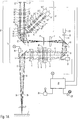
- Figure 1A 1 schematically shows an optical path through an arrangement of essential elements of an imaging system 26 of a microscopy system according to the first embodiment of the present invention, which is deployed in a plane.
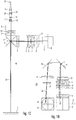
- the show FIGS. 1B, 1C and 1D schematically different views of essential elements of the imaging system of the microscopy system according to the preferred embodiment.
- Additional elements of the microscopy system are shown schematically in the form of block diagrams.
- the microscopy system according to the first preferred embodiment comprises an imaging optical system 26 which provides two pairs of imaging beam paths 2a, 2b and 2c, 2d.
- the imaging beam paths 2a and 2b and the imaging beam paths 2c and 2d respectively meet in pairs in the object plane 1.
- Main beams of the imaging beam paths 2a, 2b and 2c, 2d in each case enclose a stereo angle ⁇ in pairs.
- the microscopy system forms a stereomicroscope.
- the stereo angle ⁇ included in the object plane 1 by the first pair of imaging beam paths 2a, 2b may be different from the stereo angle (not shown in the figures) included in the object plane 1 by the second pair of imaging beam paths 2c, 2d.
- 2a, 2b and 2c, 2d paired stereo angles can also be the same size.
- the stereo angle ⁇ is between 4 ° and 6 °.
- the present invention is not limited to the above-mentioned angular range. Rather, it is sufficient if the stereo angle is not equal to zero degrees.
- the imaging beam paths 2a, 2b, 2c and 2d are designed to image an imaging field F in pairs in the object plane 1.
- the imaging field F indicates the finite (ie non-punctiform) region of an object to be examined (not shown) arranged in the object plane 1, which is imaged by the pairs of imaging beam paths 2a, 2b and 2c, 2d at a point in time (ie simultaneously).
- the size of the imaging field F depends on the size of the optical elements of the imaging system 26 and the magnification provided by the imaging system 26. In the example shown, the imaging field F has a diameter of between 10 mm and 100 mm. However, the present invention is not limited to a particular size of the imaging field F. It is only essential that the pairs of imaging beam paths 2a, 2b and 2c, 2d are designed to image a surface and not just a point in the object plane 1.
- the imaging system 26 is formed by a first optical subsystem T1 and a second optical subsystem T2, which subsystems T1 and T2 each have a plurality of optical elements.
- the first subsystem T1 has along a common optical axis K a first optical deflection element with a first optical mirror surface 3, a first, second, third, fourth and fifth optical lens 4, 5, 6, 7 and 8, a second optical deflection element with a second optical mirror surface 9, a third optical deflecting element having a third optical mirror surface 10, a sixth optical lens 11, a fourth optical deflecting element having a fourth optical mirror surface 12, a seventh and eighth optical lens 13 and 14 and prism parts 15 ', 15 "of a beam splitter assembly 15.
- the lenses 4, 5, 6, 7, 8, 11, 13 and 14 of the first subsystem T1 are penetrated jointly by the four imaging beam paths 2a, 2b, 2c and 2d. Furthermore, an afocal interface AF is arranged between the third and fourth optical lenses 6, 7, in which the imaging beam paths 2a, 2b, 2c and 2d are respectively imaged to infinity.
- the provision of the afocal interface AF allows for a modular construction of the imaging system 26. However, it is emphasized that the afocal interface AF is not required to implement the invention.
- the imaging beam paths 2a, 2b, 2c and 2d are successively reflected on the first mirror surface 3, the second mirror surface 9, the third mirror surface 10 and the fourth mirror surface 12 and deflected.
- FIG. 1D includes normal vectors of the plane defined by the first mirror surface 3 and the fourth mirror surface 12 planes relative to each other a variable angle of between 70 ° and 110 °.
- normal vectors of the planes subtended by the second mirror surface 9 and the third mirror surface 10, respectively, relative to each other include a variable angle of between 70 ° and 110 °.
- the present invention is not limited to such an angular range.
- Normal vectors of the planes spanned by the third mirror surface 10 and the fourth mirror surface 12 include a constant angle of substantially 60 ° relative to each other.
- the term "essentially 60 °" means a deviation of 60 ° by at most 5 ° and preferably at most 2 ° and particularly preferably at most 1 °.
- This arrangement of the first to fourth mirror surfaces 3, 9, 10 and 12 acts optically in total like a Porro system of the second kind. That is, the first to fourth mirror surfaces 3, 9, 10 and 12 cause both image reversal and pupil interchange. Next is through this arrangement of the mirror surfaces 3, 9, 10 and 12 achieves a particularly compact construction of the imaging system 26.
- the first to fifth lenses 4, 5, 6, 7 and 8 are arranged between the first deflecting element with the first mirror surface 3 and the second deflecting element with the second mirror surface 9.
- the sixth lens 11 is arranged between the third deflection element with the third mirror surface 10 and the fourth deflection element with the fourth mirror surface 12.
- the seventh and eighth lenses 13 and 14 are arranged between the fourth deflecting element with the fourth mirror surface 12 and the beam splitter assembly 15.
- the beam path between the second deflecting element with the second mirror surface 9 and the third deflecting element with the third mirror surface 10 is free of optical lenses.
- the first mirror surface 3 is arranged between the object plane 1 and the first lens 4 and thus between the object plane 1 and the first optically effective surface of the imaging system 26 along the imaging beam paths 2a, 2b, 2c and 2d.
- an optically active surface is understood as meaning a surface having a radius of curvature of at most 10 4 mm and preferably at most 5 * 10 3 mm and particularly preferably at most 10 3 mm.
- plane filters or cover plates should not be considered here as optically effective surface.
- the present invention is not limited to such an arrangement of the first mirror surface.
- the first effective surface of the imaging system may also be located between the first mirror surface and the object plane (not shown).
- the first deflecting element having the first mirror surface 3 is pivotable about a first pivot axis A.
- the first deflecting element is connected to a first drive 36.
- the first drive 36 is a stepper motor whose motor axis directly forms the first pivot axis A, which carries the first deflecting element having the first mirror surface 9.
- FIG. 1D leads a pivoting of the first mirror surface 3 by means of the first drive 37 about the first pivot axis A to a translational displacement of the imaging field F of the imaging system 26 in the object plane 1 in the X direction.
- FIG. 1D the first pivot axis A in a region in which the optical axis K meets the first mirror surface 3. This is in FIG. 1D in the middle of the first mirror surface 3.
- the second deflecting element having the second mirror surface 9 is pivotable about a second pivot axis B, which second pivot axis B is different from the first pivot axis A.
- the second deflecting element is connected to a second drive 37, which is formed in the embodiment shown by a stepping motor, the motor axis carries the second deflecting element and the second pivot axis B determines.
- FIG. 1D a pivoting of the second mirror surface 9 by means of the second drive 38 to a translational displacement of the imaging field F of the imaging system 26 in the object plane 1 in the Y direction.
- FIG. 1D the second pivot axis B in a region in which the optical axis K meets the second mirror surface 9. This is in FIG. 1D in the middle of the second mirror surface 9.
- the first pivot axis A with a first deflection plane, which is spanned by the incident on the first mirror surface 3 and the first mirror surface 3 failing optical axis K of the imaging beam paths 2a, 2b, 2c, 2d closes an angle of substantially 90 °.
- the optical axis K is determined by the lenses 4 to 8, 11, 13, 14 of the first subsystem T1. It is obvious that the optical axis K in the first embodiment does not run along a single straight line but is bent by the mirror surfaces 3, 9, 10, 12.
- Next also includes the second pivot axis B with a second deflection plane, which is spanned by the incident on the second mirror surface 9 and incident from the second mirror surface 9 optical axis K of the imaging beam paths 2a, 2b, 2c, 2d, an angle of substantially 90 ° one.
- the optical axis K can also main rays of the imaging beam paths 2a to 2d are used as a reference.
- the main beams of the imaging beam paths 2a, 2b, 2c and 2d must lie in a common plane for this purpose.
- the second pivot axis B is arranged substantially parallel to the first deflection plane.
- the second pivot axis B is parallel to the first deflection plane, or that the second pivot axis B intersects the first deflection plane and encloses an angle of less than 5 ° and preferably less than 2 ° with the first deflection plane, or that the second pivot axis B and the first deflection plane coincide.
- the second pivot axis B lies in the first deflection plane.
- first and second deflecting elements and the first and second drives 36,37 so form a displacing means to drive the imaging field F of the imaging system 26 by driving the first and second drives 36,37 together and pivoting the first and second mirror surfaces 3,9 the object plane 1 to translate in any direction.
- the displacement by the optics of the imaging system 26 are limited since the imaging beam paths 2a, 2b, 2c, 2d may not be displaced outside the optical lenses 4, 5, 6, 7, 8 of the imaging system 26 penetrated by them.
- the first and second drives 36, 37 are each connected to a controller 28.
- the controller 28 is connected to user interfaces in the form of a joystick 29 and a microphone 29 '.
- control commands from a user for example in the form of speech and / or eye movement and / or foot movement and / or a Receive head movement and / or a hand movement of the user and output (preferably in digital form or in analog form) to the controller.
- the control commands can specify, for example, an absolute offset, and / or a relative offset and / or only one direction of an offset in conjunction with a time span.
- control device 28 determines a desired offset of the image field F in the object plane 1 and controls the first and second drives 36, 37 accordingly.
- the controller 28 can fall back on a table in which, depending on a respective total magnification of the microscopy system required for a desired offset angular positions of the first and second Mirror surface 3, 9 are stored.
- the controller may also use a corresponding conversion formula or directly control the first and second drives 36, 37 in response to a received command from a user.
- the optical lenses 4-8 of the first subsystem T1 are arranged along the common optical axis K.
- the first lens 4 relative to the second lens 5 and the third lens 6 relative to the fourth lens 7 along the optical axis K displaced to a distance of the object plane 1 of the imaging system 26 of the microscopy system and thus a working distance and / or a Magnification of the image of an object that can be arranged in the object plane 1.
- the second subsystem T2 of the imaging system 26 also has a multiplicity of optical elements 16 '- 22', 16 "- 22", 16 “'- 22"' and 16 “" - 22 "” in which the imaging beam paths 2a, 2b However, 2c and 2d, unlike the first subsystem T1, are each separately routed. This means that the optical lenses 16 '- 21', 16 "- 21", 16 '"- 21"' and 16 "" - 21 "” are interspersed in each case by an imaging beam path 2 a, 2 b, 2 c or 2 d.
- Each imaging beam path 2a and 2b of the second subsystem T2 has a stereoscopic view of the tube optics with the eyepieces 22 ', 22 "shown only schematically, for direct visual observation by a user.
- Each imaging beam path 2c and 2d of the second subsystem T2 has a camera adapter 22 "'and 22" "for a digital camera 31'” and 31 “” for generating image data.
- a stereo camera may also be used, and the cameras 31"' and 31 “” are connected to the controller 28, respectively.
- the controller 28 receives the image data respectively generated by the cameras 31 "', 31" "and automatically detects in the image data the position of a marker (not shown).
- the marker may, for example, also be a characteristic element of the object itself automatically identified in the image data, such as a surgical element (or instrument) imaged in the image data act specific body part of a patient.
- the control via the joystick 29 and / or the microphone 29 ' is switchable to an operating state in which the controller does not directly select a desired offset from a command received via the joystick 29 and / or the microphone 29', but indirectly based on in the Image data detected position of the marker determined.
- the controller 28 controls the first and second drives 36, 37 in response to the detected position of the marker.
- the controller 28 controls the first and second drives 36, 37 so that the detected position of the marker in the image data remains substantially constant.
- the controller pivots the first and second mirror surfaces 3, 9 by means of the first and second drives 36, 37 such that a marker detected, for example, in the center of the image data, even after a displacement of the marker relative to the object plane in the middle of the Image data remains.
- the term "substantially constant” should be understood to mean that the relative position of the marker in the image data does not change by more than 30% of a diameter of the imaging field F and preferably by not more than 10% of the diameter of the imaging field F.
- a physical beam splitter 15 is provided, which has a partially transparent mirror surface, which is penetrated by a first pair of imaging beam paths 2a and 2b and at which a second pair of imaging beam paths 2c and 2d reflected is.
- the microscopy system provides a secondary beam path 24, which passes through the third mirror surface 10 of the third deflection element in a central region.
- This central region may preferably lie between beam cross-sectional areas of the imaging beam paths 2a, 2b, 2c and 2d.
- the third mirror surface 10 at least partially a transparency for radiation of the secondary beam path 24, which is greater than a transparency for radiation of the imaging beam paths 2a, 2b, 2c, 2d.
- the coupling of the secondary beam path 24 can alternatively be done in a different way.
- the secondary beam path 24 is formed by an illumination optical unit 30 of an illumination system, wherein the illumination system further comprises a radiation source 23.
- This illumination system is not part of the imaging system 26.
- an infrared observation system (not shown) with infrared imaging optics and an infrared camera may be provided, the infrared imaging optics providing the secondary beam path 24.
- a laser may also be provided with a beam guidance system (not shown) which provides the secondary beam path 24.
- a beam guidance system (not shown) which provides the secondary beam path 24.
- the first, second, third and fourth deflecting elements are each an optical mirror.
- the deflecting elements may, for example, also be prisms, each having at least one mirror surface.
- the first, second, third and fourth deflecting elements can each optionally have a plurality of mirror surfaces for deflecting the imaging beam paths 2a, 2b, 2c and 2d. In addition, more or fewer than two pairs of imaging beam paths may be provided.
- the first, second, third and fourth mirror surfaces are arranged so that the common optical axis K of the first subsystem T1 is folded by the mirror surfaces so as to be in at least first and second planes to each other are substantially parallel, as well as in at least a third plane, which is substantially perpendicular to the two first and second planes, is located.
- the conditions of "substantially parallel” and “substantially perpendicular” should be considered fulfilled if the third plane, the two first and second planes each at an angle of between 60 ° and 120 ° and preferably between 80 ° and 100 ° and more preferably between 85 ° and 95 ° and in particular 90 °.
- the first plane through the incident on the first mirror surface 3 and optic axis K, the second plane through the incident on the fourth mirror surface 12 and optic axis K, and the third plane through which the second ( or third) mirror surface 9 (or 10) on and falling optical axis K spanned.
- the microscopy system according to the first preferred embodiment is particularly well suited for use as a surgical microscope.
- the reason is that by pivoting the first and second mirror surfaces 3, 9 in a particularly simple, fast, reliable and vibration-free manner, it is possible for a user to displace the imaging field F in the object plane 1.
- the controller 28 may effect automatic image stabilization and image tracking by exposing the first and second mirror surfaces 3, 9 automatically in response to the position of the marker detected in image data.
- FIGS. 1B to 1D For the sake of clarity, only one imaging beam path 2a was shown in each case. For the same reason, the imaging beam paths 2c and 2d are in Figure 1A not fully shown.
- FIGS. 1B, 1C and 1D omitted a representation of the illumination system and the optical axis K of the first subsystem T1.
- FIG. 1D schematically shows a perspective view in order (in contrast to the in Figure 1A deployed in a plane) to clarify the actual spatial arrangement of essential elements of the imaging system 26 of the microscopy system according to the first preferred embodiment.
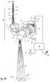
- FIG. 2 A second embodiment of a microscopy system according to the present invention is described. It shows FIG. 2 schematically a beam path through an unfolded in a plane arrangement of essential elements of an imaging system of the microscopy system. Additional elements of the microscopy system are shown schematically in the form of block diagrams. Since the structure of the microscopy system according to the second embodiment is similar in many parts to the structure of the micro copy system according to the first embodiment described in detail, only the differences between the first and second embodiments will be explained.
- a rotation of the created by the imaging system 26 image of the object plane 1 of the microscope system can be arranged object and thus the image field F is caused when the first and second axes of rotation A, B of the first and second mirror surface 3, 9 not each with a respective deflection plane, of the incident on the respective mirror surface 3, 9 and from the respective mirror surface 3, 9 failing optical axis K and / or main rays of the imaging beam paths 2a to 2d of first subsystem T1 is clamped, enclose an angle of substantially 90 °.
- the microscope system according to the second embodiment additionally comprises a compensation device, which causes an (additional) rotation of the image of the imaging field F produced by the imaging system 26.
- the adjustable prism arrangements 27' and 27" are connected to the controller 28 and each have at least one and preferably each have at least two mirror surfaces, which are rotatable relative to each other for optical rotation of the image provided by the imaging system 26.
- the present invention is not limited to such a construction of the optical compensation device.
- the controller 28 controls the adjustable prism assemblies 27 'and 27 "in response to control of the first and second drives 36, 37 such that rotation caused by pivoting of the first and second mirror surfaces 3, 9 is provided by the imaging system 26 Illustration of the object by one of the adjustable prism assemblies 27 ', 27 "caused opposing rotation of the image is canceled.
- the microscope system for compensating a rotation of the image of the object provided by the imaging system in the imaging beam paths 2c and 2d has a further compensation device in the form of an external graphics processor 27 *.
- the graphics processor 27 * is connected to the cameras 31 "'and 31""and to the controller 28.
- the controller 28 controls the graphics processor 27 * in response to a control of the first and second drives 36, 37 such that one by pivoting the first and second mirror surface 3, 9 rotation of the image provided by the imaging system 26 of the object is canceled by one of the graphics processor 27 * caused by electronic image processing rotation of the image with additional adjustment of the stereo base.
- the controller 28 takes into account both the degree of pivoting of the respective mirror surface 3, 9 and the orientation of the respective pivot axis A, B relative to the respectively deflected imaging beam path 2a, 2b, 2c and 2d or the optical axis K of the first subsystem T1.
- the compensation for example, by preferably controlled mechanical rotation of the camera pair 31 "', 31""done.
- the illumination beam path 24 'of the microscopy system according to the second embodiment is not deflected by the pivotable first and second mirror surfaces 3, 9.
- the microscopy system has an additional illumination mirror 38.
- the illumination mirror 38 deflects the illumination beam path 24 'and, in the embodiment shown, is pivotable about two mutually orthogonal axes by means of a third drive 39 in the form of a stepping motor, both in a plane spanned by the illumination mirror 38.
- the two axes of the illumination mirror 38 preferably intersect in a region in which the illumination beam path 24 'meets the illumination mirror 38.
- the third drive 39 is connected to the controller 28.
- the controller 28 controls the third drive 39 as a function of a control of the first and second drives 36, 37 so that the illumination mirror 38 is pivoted in a pivoting of the first and second mirror surfaces 3, 9 for the purpose of shifting the imaging field F in the object plane 1 in that the illumination beam path 24 'follows the displacement of the imaging field F.
- the illumination beam path 24 ' can alternatively be any secondary beam path for observing and / or influencing an object that can be arranged in the object plane 1.
- FIG. 3 shows an embodiment of a microscope system, which is not the subject of the claims. It shows FIG. 3 schematically a beam path through essential elements of the microscopy system, with additional elements of the microscopy system are shown schematically in the form of block diagrams.
- the microscopy system has an imaging system 26 * to image an object (not shown) disposed in an object plane 1.
- the imaging system 26 * (as in the first and second embodiments described above) consists of a first subsystem T1 * with a plurality of optical lenses 4 *, 5 * and 6 * in which imaging beam paths 2a *, 2b * are guided together, and a second subsystem T2 * with multiple optical lenses 16 '* - 20' *, 22 '*, 16' '* - 20 "*, 22" *, in which the imaging beam paths 2a *, 2b * are performed separately together.
- lenses of the first and second subsystems T1 *, T2 * can be displaced relative to one another in order to adapt a working distance or to change the magnification of the image. A more detailed description of these elements will be omitted.
- imaging beam paths 2a *, 2b * are provided which enclose a stereo angle ⁇ in the object plane and are supplied via eyepieces 22 '*, 22 "* to eyes 37' *, 37" * of a user.
- a separate mirror surface 3 * which is not part of the imaging system 26 *, is arranged between the imaging system 26 * and the object plane 1 *. The area between the mirror surface 3 * and the object plane 1 * is thus free of optically effective surfaces and / or elements.
- the mirror surface 3 * is connected to a drive 36 *, which is designed to pivot the mirror surface 3 * selectively about a pivot point P in an arbitrary direction.
- the pivot point P lies on an optical axis K of the first subsystem T1 * defined by the optical lenses 4 *, 5 * and 6 *.
- FIG. 3 is the pivot point P in the middle of the mirror surface 3 *.
- the second subsystem T2 * of in FIG. 3 shown imaging system 26 * for each imaging beam path 2a *, 2b * a compensation device 27 '*, 27 "* in the form of an adjustable prism arrangement.
- the controller 28 drives the drive 36 * to turn on (in FIG. 3 not shown) imaging field of the imaging system 26 * in the object plane 1 to move in any direction.
- the controller 28 automatically controls the drives of the compensation devices 27 '*, 27 "* so that the compensation devices 27' *, 27" * automatically compensate for an image rotation caused by a pivoting of the mirror surface 3 *.
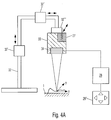
- FIG. 4A Fig. 12 schematically shows a side view of the structure of the microscopy system according to the second embodiment of the present invention.
- the microscopy system may further comprise a tripod 32 carrying a surgical microscope 33.
- the surgical microscope 33 comprises the imaging system 26, the compensation device 27 and the offset device 34 with each in the structure described in the second embodiment.
- About drives 32 ', 32 ", 32'” allows the tripod 32 a translational and rotational displacement of the surgical microscope 33 relative to the object plane.
- the controller 28 in FIG. 4A To input a desired offset of the imaging field relative to the object plane, the controller 28 in FIG. 4A a keyboard 29 '' on.
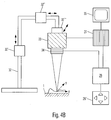
- FIG. 4B Fig. 12 is a schematic side view showing a structure of a microscopy system according to a fourth embodiment of the present invention.
- FIG. 4B shown fourth embodiment of the in FIG. 4A in particular in that the compensation device 27 and the offset device 34 are not included in the surgical microscope 33 but are separate modules that can be connected to the surgical microscope 33.
- the compensation device 27 is formed by a graphics processor which outputs a picture received by the operation microscope 33 and rotated in response to the control 28 and corrected for its stereo base via a monitor 35.
- the present invention is not limited thereto. Rather, any desired number of pivotable mirror surfaces can be provided in order to displace the imaging field of the imaging system in the object plane.
- the gift of the mirror surfaces for example, optionally be done by the respective mirror surface is pivoted by more than one pivot axis, or in that the respective mirror surface is rotated about an axis of rotation which includes a normal to the mirror surface non-zero angle. This axis of rotation can coincide with an incident on the respective mirror surface optical axis. Through such a rotation of Mirror surface is at the same time causes a pivoting of the mirror surface relative to the optical axis incident on the mirror surface, resulting in a displacement of the imaging field in the object plane.
- the present invention provides a microscopy system which, by pivoting at least one mirror surface, permits displacement of an imaging field of an imaging system of a microscopy system in an object plane in a particularly simple, reliable and vibration-free manner.
- a microscopy system which, by pivoting at least one mirror surface, permits displacement of an imaging field of an imaging system of a microscopy system in an object plane in a particularly simple, reliable and vibration-free manner.
- it is possible in a particularly convenient way by means of the microscopy system according to the invention to compensate for movements (and in particular also periodic movements) of a viewed object by corresponding displacement of the imaging field and thus to maintain a viewed object in the imaging field.
- the reason is that only one mirror surface must be pivoted and thus can be dispensed with a displacement of the entire imaging system of the microscopy system.
- the displacement may be controlled by a controller which determines a desired offset automatically or based on a user input.
- a rotation of the image of an object created by the imaging system which is possibly caused by a pivoting of the at least one mirror surface, can be corrected automatically by means of a compensation device.
- the controller controls the compensation device as a function of a measure and a direction of pivoting of the at least one mirror surface.
- Such a microscopy system is particularly suitable for use as a surgical microscope.
Landscapes
- Physics & Mathematics (AREA)
- Health & Medical Sciences (AREA)
- Optics & Photonics (AREA)
- General Physics & Mathematics (AREA)
- Surgery (AREA)
- Chemical & Material Sciences (AREA)
- Life Sciences & Earth Sciences (AREA)
- Analytical Chemistry (AREA)
- General Health & Medical Sciences (AREA)
- Medical Informatics (AREA)
- Molecular Biology (AREA)
- Animal Behavior & Ethology (AREA)
- Heart & Thoracic Surgery (AREA)
- Public Health (AREA)
- Veterinary Medicine (AREA)
- Engineering & Computer Science (AREA)
- Biomedical Technology (AREA)
- Pathology (AREA)
- Oral & Maxillofacial Surgery (AREA)
- Nuclear Medicine, Radiotherapy & Molecular Imaging (AREA)
- Microscoopes, Condenser (AREA)
Applications Claiming Priority (2)
| Application Number | Priority Date | Filing Date | Title |
|---|---|---|---|
| DE102006010767A DE102006010767B4 (de) | 2006-03-08 | 2006-03-08 | Mikroskopiesystem |
| PCT/EP2007/002025 WO2007101695A1 (de) | 2006-03-08 | 2007-03-08 | Mikroskopiesystem mit einem schwenkbaren spiegelpaar zur kompensation eines objektversatzes |
Publications (3)
| Publication Number | Publication Date |
|---|---|
| EP1991899A1 EP1991899A1 (de) | 2008-11-19 |
| EP1991899B1 EP1991899B1 (de) | 2016-05-11 |
| EP1991899B9 true EP1991899B9 (de) | 2016-10-05 |
Family
ID=38007153
Family Applications (1)
| Application Number | Title | Priority Date | Filing Date |
|---|---|---|---|
| EP07723118.1A Active EP1991899B9 (de) | 2006-03-08 | 2007-03-08 | Mikroskopiesystem mit einem schwenkbaren spiegelpaar zur kompensation eines objektversatzes |
Country Status (5)
| Country | Link |
|---|---|
| US (1) | US20090059363A1 (ja) |
| EP (1) | EP1991899B9 (ja) |
| JP (1) | JP5327670B2 (ja) |
| DE (1) | DE102006010767B4 (ja) |
| WO (1) | WO2007101695A1 (ja) |
Families Citing this family (18)
| Publication number | Priority date | Publication date | Assignee | Title |
|---|---|---|---|---|
| JP3997890B2 (ja) | 2001-11-13 | 2007-10-24 | 松下電器産業株式会社 | 送信方法及び送信装置 |
| DE102006009452B4 (de) * | 2005-10-20 | 2010-07-01 | Carl Zeiss Surgical Gmbh | Stereomikroskop |
| JP5023934B2 (ja) * | 2007-09-28 | 2012-09-12 | 株式会社ニコン | 顕微鏡 |
| DE102009019575A1 (de) | 2009-04-28 | 2010-11-11 | Carl Zeiss Surgical Gmbh | Stereoskopisches optisches Beobachtungsgerät und stereoskopisches optisches Beobachtungssystem |
| DE102009021087B4 (de) | 2009-05-13 | 2015-03-05 | Carl Zeiss Meditec Ag | Stereo-Mikroskopiesystem und optischer Aufbau zur Verwendung in einem solchen Stereo-Mikroskopiesystem |
| DE102009046449B3 (de) * | 2009-11-06 | 2011-05-12 | Leica Instruments (Singapore) Pte. Ltd. | Stereomikroskop |
| JP2012042669A (ja) * | 2010-08-18 | 2012-03-01 | Sony Corp | 顕微鏡制御装置及び光学的歪み補正方法 |
| GB2497092A (en) | 2011-11-29 | 2013-06-05 | John Sharpe Ward | Stereoscopic microscope with two separate adjustment means in the path of left and right sub-beams |
| DE102012006749B4 (de) | 2012-04-03 | 2020-06-18 | Carl Zeiss Meditec Ag | Stereomikroskop |
| GB201220422D0 (en) | 2012-11-13 | 2012-12-26 | Cairn Res Ltd | Optical imaging device |
| KR101371384B1 (ko) * | 2013-01-10 | 2014-03-07 | 경북대학교 산학협력단 | 트랙킹 시스템 및 이를 이용한 트랙킹 방법 |
| DE102014102425B4 (de) | 2014-02-25 | 2018-06-28 | Carl Zeiss Meditec Ag | Mikroskopsystem und Mikroskopieverfahren unter Verwendung digitaler Marker |
| DE102015216572A1 (de) | 2015-08-31 | 2016-05-12 | Carl Zeiss Meditec Ag | Vorrichtung zur Umlenkung eines optischen Strahlengangs sowie Medizinische Visualisierungseinrichtung mit einer solchen Vorrichtung |
| DE102016113978B4 (de) * | 2016-07-28 | 2021-09-02 | Lilas Gmbh | Vorrichtung zum Ablenken einer Laserstrahlung oder zum Ablenken von Licht |
| EP3285107B2 (en) | 2016-08-16 | 2024-02-28 | Leica Instruments (Singapore) Pte. Ltd. | Surgical microscope with gesture control and method for a gesture control of a surgical microscope |
| EP3531184B1 (en) * | 2018-02-23 | 2022-06-29 | Leica Instruments (Singapore) Pte. Ltd. | Surgical microscope with movable beam deflector, method for operating the same and retrofit-kit |
| TWI738407B (zh) * | 2019-11-07 | 2021-09-01 | 宏達國際電子股份有限公司 | 頭戴式顯示裝置 |
| DE102023123537B3 (de) | 2023-08-31 | 2024-09-12 | Carl Zeiss Meditec Ag | Optisches Beobachtungssystem sowie Verfahren zum Aufnehmen von Fluoreszenzbildern |
Family Cites Families (40)
| Publication number | Priority date | Publication date | Assignee | Title |
|---|---|---|---|---|
| US4601550A (en) * | 1983-08-08 | 1986-07-22 | Tokyo Kogaku Kikai Kabushiki Kaisha | Stereo-microscope with a common objective lens system |
| DE3336519A1 (de) | 1983-10-07 | 1985-04-25 | Fa. Carl Zeiss, 7920 Heidenheim | Monipulator an operationsmikroskopen |
| DE3833876A1 (de) * | 1988-10-05 | 1990-04-12 | Zeiss Carl Fa | Zwei optisch-mechanisch gekoppelte operationsmikroskope mit koaxialer beleuchtung |
| US5253106A (en) * | 1992-03-20 | 1993-10-12 | Amarel Precision Instruments, Inc. | Oblique viewing system for microscopes |
| US5612816A (en) * | 1992-04-28 | 1997-03-18 | Carl-Zeiss-Stiftung | Endoscopic attachment for a stereoscopic viewing system |
| US5225923A (en) * | 1992-07-09 | 1993-07-06 | General Scanning, Inc. | Scanning microscope employing improved scanning mechanism |
| JP3454851B2 (ja) * | 1992-10-27 | 2003-10-06 | オリンパス光学工業株式会社 | 実体顕微鏡 |
| DE4336715C2 (de) * | 1992-10-27 | 1999-07-08 | Olympus Optical Co | Stereomikroskop |
| US5701196A (en) * | 1993-11-05 | 1997-12-23 | Olympus Optical Co., Ltd | Stereomicroscope |
| CH689903A5 (de) * | 1994-12-23 | 2000-01-14 | Zeiss Carl Fa | Zoom-System für mindestens zwei stereoskopische Beobachtungs- oder Dokumentationsstrahlengänge. |
| DE59600739D1 (de) * | 1995-02-03 | 1998-12-03 | Leica Mikroskopie Sys Ag | Stereomikroskop |
| JPH10260359A (ja) * | 1997-03-19 | 1998-09-29 | Olympus Optical Co Ltd | 像回転装置 |
| JP2001356272A (ja) * | 2000-06-12 | 2001-12-26 | Olympus Optical Co Ltd | 画像取得方法及び走査型光学顕微鏡 |
| US6433929B1 (en) * | 2000-06-12 | 2002-08-13 | Olympus Optical Co., Ltd. | Scanning optical microscope and method of acquiring image |
| US6628457B2 (en) * | 2000-07-11 | 2003-09-30 | Asahi Kogaku Kogyo Kabushiki Kaisha | Antivibration microscope |
| JP3857888B2 (ja) * | 2000-07-11 | 2006-12-13 | ペンタックス株式会社 | ビデオ式顕微鏡への防振機構の組込みの決定方法 |
| DE10140402B4 (de) * | 2000-09-26 | 2012-08-30 | Carl Zeiss Meditec Ag | Bildumkehrsystem, Ophthalmoskopie-Vorsatzmodul und Operationsmikroskop |
| JP2004510198A (ja) * | 2000-09-26 | 2004-04-02 | カール−ツアイス−スチフツング | 像反転系、検眼鏡補助モジュール、手術用顕微鏡 |
| EP1333305B8 (de) * | 2002-02-04 | 2007-08-01 | Carl Zeiss Surgical GmbH | Stereo-Untersuchungssysteme und Stereo-Bilderzeugungsvorrichtung sowie Verfahren zum Betrieb einer solchen |
| DE10221796A1 (de) * | 2002-05-15 | 2004-01-29 | Carl Zeiss | Operationsmikroskop und Bildaufnahmeeinrichtung für Operationsmikroskop |
| DE10330581B4 (de) * | 2002-08-23 | 2015-02-19 | Carl Zeiss Meditec Ag | Verstellvorrichtung |
| JP4197915B2 (ja) * | 2002-09-19 | 2008-12-17 | オリンパス株式会社 | 実体顕微鏡用撮影装置 |
| DE10255961B3 (de) * | 2002-11-29 | 2004-04-08 | Leica Microsystems (Schweiz) Ag | Stereomikroskop |
| DE10255965A1 (de) * | 2002-11-29 | 2004-06-09 | Leica Microsystems (Schweiz) Ag | Stereomikroskop |
| DE10255967A1 (de) * | 2002-11-29 | 2004-06-09 | Leica Microsystems (Schweiz) Ag | Vorrichtung zur Ausspiegelung eines stereoskopischen Beobachtungsstrahlengangs |
| DE10255960A1 (de) * | 2002-11-29 | 2004-06-24 | Leica Microsystems (Schweiz) Ag | Stereomikroskop |
| DE10255964A1 (de) * | 2002-11-29 | 2004-07-01 | Siemens Ag | Photovoltaisches Bauelement und Herstellungsverfahren dazu |
| US7159831B2 (en) * | 2003-02-21 | 2007-01-09 | Carl-Zeiss-Stiftung | Adjusting device |
| DE10312471B4 (de) * | 2003-03-20 | 2006-04-13 | Leica Microsystems (Schweiz) Ag | Mikroskop, insbesondere Stereomikroskop |
| DE10312681B4 (de) * | 2003-03-21 | 2005-09-15 | Carl Zeiss | Mikroskopiesystem |
| DE10332603B4 (de) * | 2003-07-17 | 2006-04-06 | Leica Microsystems (Schweiz) Ag | Stereomikroskop |
| DE10355527A1 (de) * | 2003-11-21 | 2005-06-09 | Carl Zeiss Jena Gmbh | Mikroskopkamera |
| JP5093979B2 (ja) * | 2003-12-10 | 2012-12-12 | カール ツァイス メディテック アーゲー | 観察装置用対物レンズ、顕微鏡ならびに対物レンズの調節方法 |
| JP2005301065A (ja) * | 2004-04-14 | 2005-10-27 | Olympus Corp | 観察装置 |
| DE602005007403D1 (de) * | 2004-03-25 | 2008-07-24 | Olympus Corp | Scannendes konfokales Mikroskop |
| JP4576876B2 (ja) * | 2004-05-10 | 2010-11-10 | 株式会社ニコン | 顕微鏡システム |
| JP4752208B2 (ja) * | 2004-07-23 | 2011-08-17 | 株式会社ニコン | 光学顕微鏡システムおよびこれを用いた試料動画像生成方法 |
| CN100585449C (zh) * | 2005-01-27 | 2010-01-27 | 伦斯勒理工学院 | 可适应性扫描光学显微镜 |
| DE102006012388A1 (de) * | 2005-10-20 | 2007-04-26 | Carl Zeiss Surgical Gmbh | Mikroskopiesystem |
| DE102006009452B4 (de) * | 2005-10-20 | 2010-07-01 | Carl Zeiss Surgical Gmbh | Stereomikroskop |
-
2006
- 2006-03-08 DE DE102006010767A patent/DE102006010767B4/de active Active
-
2007
- 2007-03-08 EP EP07723118.1A patent/EP1991899B9/de active Active
- 2007-03-08 JP JP2008557670A patent/JP5327670B2/ja not_active Expired - Fee Related
- 2007-03-08 WO PCT/EP2007/002025 patent/WO2007101695A1/de active Application Filing
-
2008
- 2008-09-05 US US12/205,742 patent/US20090059363A1/en not_active Abandoned
Also Published As
| Publication number | Publication date |
|---|---|
| JP2009529145A (ja) | 2009-08-13 |
| WO2007101695A1 (de) | 2007-09-13 |
| DE102006010767B4 (de) | 2008-04-17 |
| US20090059363A1 (en) | 2009-03-05 |
| JP5327670B2 (ja) | 2013-10-30 |
| EP1991899B1 (de) | 2016-05-11 |
| EP1991899A1 (de) | 2008-11-19 |
| DE102006010767A1 (de) | 2007-09-13 |
Similar Documents
| Publication | Publication Date | Title |
|---|---|---|
| EP1991899B9 (de) | Mikroskopiesystem mit einem schwenkbaren spiegelpaar zur kompensation eines objektversatzes | |
| DE10027166B4 (de) | Stereoskopmikroskop | |
| DE10133671B4 (de) | Mikroskopeinrichtung | |
| DE102011010262B4 (de) | Optisches Beobachtungsgerät mit wenigstens zwei jeweils einen Teilstrahlengang aufweisenden optischen Übertragungskanälen | |
| DE102005021569A1 (de) | Optisches Mikroskopsystem, Mikroskop, und System zum Erzeugen virtueller Abbilder | |
| CH696044A5 (de) | Mikroskop, insbesondere Operationsmikroskop. | |
| DE3127990C2 (de) | Optisches Beobachtungsgerät | |
| DE102007021981A1 (de) | Optisches Gerät mit Vibrationskompensation | |
| DE102013208306A1 (de) | Stereoskopisches Mikroskop | |
| EP1460466B1 (de) | Mikroskop, insbesondere Stereomikroskop | |
| EP2802932B9 (de) | Optisches system zur abbildung eines objekts | |
| DE102011054087A1 (de) | Optische Bildversatzvorrichtung, optische Bildstabilisierungsvorrichtung und optisches Beobachtungsgerät | |
| DE102010003640A1 (de) | Video-Stereomikroskop | |
| DE602005000964T2 (de) | Rasterlichtmikroskop | |
| DE10130119A1 (de) | Videomikroskop | |
| EP1731944A1 (de) | Fernglas | |
| DE102012206230A1 (de) | Optisches System zur Abbildung eines Objekts | |
| EP1731945A1 (de) | Fernglas mit Mitteln zum Ausglich von Verwacklungen | |
| EP1498762A1 (de) | Mikroskop | |
| DE69426246T2 (de) | Optische Vorrichtung mit einer Funktion zur Verhinderung von Bildzittern | |
| EP3908874B1 (de) | Optisches system zur abbildung eines objekts sowie verfahren zum betrieb des optischen systems | |
| DE102005040471A1 (de) | Mikroskop | |
| DE102007051405B4 (de) | Lichtmikroskop | |
| DE102019134329B4 (de) | Aufhängung für digitales Operationsmikroskop mit Positionskorrektur, optisches Gerät und Verfahren zu dessen Betrieb | |
| DE102017109202A1 (de) | Optische Beobachtungsgerätevorrichtung, optisches Beobachtungsgerätesystem und Verfahren zum Ausbalancieren eines optischen Beobachtungsgerätesystems |
Legal Events
| Date | Code | Title | Description |
|---|---|---|---|
| PUAI | Public reference made under article 153(3) epc to a published international application that has entered the european phase |
Free format text: ORIGINAL CODE: 0009012 |
|
| 17P | Request for examination filed |
Effective date: 20080901 |
|
| AK | Designated contracting states |
Kind code of ref document: A1 Designated state(s): DE ES FR GB IT |
|
| 17Q | First examination report despatched |
Effective date: 20090203 |
|
| DAX | Request for extension of the european patent (deleted) | ||
| RBV | Designated contracting states (corrected) |
Designated state(s): DE ES FR GB IT |
|
| RAP1 | Party data changed (applicant data changed or rights of an application transferred) |
Owner name: CARL ZEISS MEDITEC AG |
|
| GRAP | Despatch of communication of intention to grant a patent |
Free format text: ORIGINAL CODE: EPIDOSNIGR1 |
|
| INTG | Intention to grant announced |
Effective date: 20150817 |
|
| REG | Reference to a national code |
Ref country code: DE Ref legal event code: R079 Ref document number: 502007014808 Country of ref document: DE Free format text: PREVIOUS MAIN CLASS: G02B0021000000 Ipc: G02B0021220000 |
|
| GRAS | Grant fee paid |
Free format text: ORIGINAL CODE: EPIDOSNIGR3 |
|
| RIC1 | Information provided on ipc code assigned before grant |
Ipc: G02B 21/22 20060101AFI20160112BHEP Ipc: G02B 27/64 20060101ALI20160112BHEP Ipc: G02B 26/08 20060101ALI20160112BHEP Ipc: G02B 21/00 20060101ALI20160112BHEP |
|
| INTG | Intention to grant announced |
Effective date: 20160203 |
|
| GRAA | (expected) grant |
Free format text: ORIGINAL CODE: 0009210 |
|
| AK | Designated contracting states |
Kind code of ref document: B1 Designated state(s): DE ES FR GB IT |
|
| REG | Reference to a national code |
Ref country code: GB Ref legal event code: FG4D Free format text: NOT ENGLISH |
|
| REG | Reference to a national code |
Ref country code: DE Ref legal event code: R096 Ref document number: 502007014808 Country of ref document: DE |
|
| GRAT | Correction requested after decision to grant or after decision to maintain patent in amended form |
Free format text: ORIGINAL CODE: EPIDOSNCDEC |
|
| PG25 | Lapsed in a contracting state [announced via postgrant information from national office to epo] |
Ref country code: ES Free format text: LAPSE BECAUSE OF FAILURE TO SUBMIT A TRANSLATION OF THE DESCRIPTION OR TO PAY THE FEE WITHIN THE PRESCRIBED TIME-LIMIT Effective date: 20160511 |
|
| PG25 | Lapsed in a contracting state [announced via postgrant information from national office to epo] |
Ref country code: IT Free format text: LAPSE BECAUSE OF FAILURE TO SUBMIT A TRANSLATION OF THE DESCRIPTION OR TO PAY THE FEE WITHIN THE PRESCRIBED TIME-LIMIT Effective date: 20160511 |
|
| REG | Reference to a national code |
Ref country code: DE Ref legal event code: R097 Ref document number: 502007014808 Country of ref document: DE |
|
| PLBE | No opposition filed within time limit |
Free format text: ORIGINAL CODE: 0009261 |
|
| STAA | Information on the status of an ep patent application or granted ep patent |
Free format text: STATUS: NO OPPOSITION FILED WITHIN TIME LIMIT |
|
| REG | Reference to a national code |
Ref country code: FR Ref legal event code: PLFP Year of fee payment: 11 |
|
| 26N | No opposition filed |
Effective date: 20170214 |
|
| REG | Reference to a national code |
Ref country code: FR Ref legal event code: PLFP Year of fee payment: 12 |
|
| P01 | Opt-out of the competence of the unified patent court (upc) registered |
Effective date: 20230530 |
|
| PGFP | Annual fee paid to national office [announced via postgrant information from national office to epo] |
Ref country code: DE Payment date: 20240320 Year of fee payment: 18 Ref country code: GB Payment date: 20240320 Year of fee payment: 18 |
|
| PGFP | Annual fee paid to national office [announced via postgrant information from national office to epo] |
Ref country code: FR Payment date: 20240322 Year of fee payment: 18 |