EP1991899B9 - Microscopy system with a pivoting mirror pair for compensating an object offset - Google Patents
Microscopy system with a pivoting mirror pair for compensating an object offset Download PDFInfo
- Publication number
- EP1991899B9 EP1991899B9 EP07723118.1A EP07723118A EP1991899B9 EP 1991899 B9 EP1991899 B9 EP 1991899B9 EP 07723118 A EP07723118 A EP 07723118A EP 1991899 B9 EP1991899 B9 EP 1991899B9
- Authority
- EP
- European Patent Office
- Prior art keywords
- imaging
- mirror face
- offset
- object plane
- microscopy system
- Prior art date
- Legal status (The legal status is an assumption and is not a legal conclusion. Google has not performed a legal analysis and makes no representation as to the accuracy of the status listed.)
- Active
Links
Images


Classifications
-
- G—PHYSICS
- G02—OPTICS
- G02B—OPTICAL ELEMENTS, SYSTEMS OR APPARATUS
- G02B26/00—Optical devices or arrangements for the control of light using movable or deformable optical elements
- G02B26/08—Optical devices or arrangements for the control of light using movable or deformable optical elements for controlling the direction of light
- G02B26/0816—Optical devices or arrangements for the control of light using movable or deformable optical elements for controlling the direction of light by means of one or more reflecting elements
-
- A—HUMAN NECESSITIES
- A61—MEDICAL OR VETERINARY SCIENCE; HYGIENE
- A61B—DIAGNOSIS; SURGERY; IDENTIFICATION
- A61B90/00—Instruments, implements or accessories specially adapted for surgery or diagnosis and not covered by any of the groups A61B1/00 - A61B50/00, e.g. for luxation treatment or for protecting wound edges
- A61B90/36—Image-producing devices or illumination devices not otherwise provided for
-
- G—PHYSICS
- G02—OPTICS
- G02B—OPTICAL ELEMENTS, SYSTEMS OR APPARATUS
- G02B21/00—Microscopes
- G02B21/0004—Microscopes specially adapted for specific applications
- G02B21/0012—Surgical microscopes
-
- G—PHYSICS
- G02—OPTICS
- G02B—OPTICAL ELEMENTS, SYSTEMS OR APPARATUS
- G02B21/00—Microscopes
- G02B21/18—Arrangements with more than one light path, e.g. for comparing two specimens
- G02B21/20—Binocular arrangements
- G02B21/22—Stereoscopic arrangements
-
- A—HUMAN NECESSITIES
- A61—MEDICAL OR VETERINARY SCIENCE; HYGIENE
- A61B—DIAGNOSIS; SURGERY; IDENTIFICATION
- A61B90/00—Instruments, implements or accessories specially adapted for surgery or diagnosis and not covered by any of the groups A61B1/00 - A61B50/00, e.g. for luxation treatment or for protecting wound edges
- A61B90/20—Surgical microscopes characterised by non-optical aspects
-
- G—PHYSICS
- G02—OPTICS
- G02B—OPTICAL ELEMENTS, SYSTEMS OR APPARATUS
- G02B27/00—Optical systems or apparatus not provided for by any of the groups G02B1/00 - G02B26/00, G02B30/00
- G02B27/64—Imaging systems using optical elements for stabilisation of the lateral and angular position of the image
- G02B27/642—Optical derotators, i.e. systems for compensating for image rotation, e.g. using rotating prisms, mirrors
Definitions
- the present invention relates to a microscopy system for imaging an object that can be arranged in an object plane of the microscopy system.
- a vibration-proof microscope is out of the DE 101 33 671 A1 known.
- the microscope comprises an optical microscope system which generates an object image in a field of predetermined format, a first sensor for measuring the inclination of the entire microscope system, a second sensor for measuring the movement of the entire microscope system, a deflection device for deflecting object light passing through the microscope system into any one Direction and at any angle, and a control unit for adjusting the deflection and the deflection angle of the object light with the deflection device depending on the measurements of the first sensor and the second sensor, so that the image remains stationary despite a tilt or movement of the microscope system.
- the microscopy system comprises at least one imaging system which provides at least one imaging beam path for imaging a finite (i.e., non-punctiform) imaging field of the object plane and a displacement device configured to translate the imaging field of the imaging system in the object plane.
- microscopy systems are used, for example, in medical technology as surgical microscopes to observe an object arranged in an object plane.
- the surgical microscope is usually carried by a stand attached to a ceiling or standing on the ground tripod.
- the tripod serves as a shifter to allow positioning of the surgical microscope over a viewed object.
- the tripod usually allows a translational displacement of the imaging system with up to three degrees of freedom (forward / backward, left / right, up / down) and usually a rotational movement of the surgical microscope with at least one degree of freedom (pivoting relative to the horizontal).
- tripods are relatively expensive, since they have on the one hand in the locked state a great stability and freedom from vibration and at the same time must be easily operable.
- the tripod must be made sufficiently solid, and the surgical microscope worn by him must be balanced by springs or counterweights in any possible position of the surgical microscope.
- positioning must be possible with high accuracy since an imaging field (area of the object plane imaged by an imaging system of the surgical microscope) of the Surgical microscope is very small especially at high magnification.
- this displacement device has the disadvantage that it is technically complex and, due to its own weight, makes a comparatively more elaborate and more stable tripod necessary. Furthermore, an acceleration of the inertial mass of the surgical microscope is still required for a displacement of the surgical microscope. The inert mass of the Surgical microscope prevents for a quick shift. On the other hand there is a risk that vibrations are generated and transmitted to the tripod with a rapid positive or negative acceleration of the inertial mass of the surgical microscope. In addition, direct visual observation after a surgical microscope shift requires that the user at least slightly adjust his working position.
- the document WO 2006/081031 A2 discloses an optical adaptive scanning microscope ASOM.
- at least one objective lens is arranged between the object and a pivotable mirror, with different regions of the object plane being scanned in succession as a result of the pivoting of the mirror.
- the overall picture is obtained from a plurality of such samples.
- the document GB 2 149 045 A teaches placing a laser beam at a desired position within an imaging field by means of a two-axis pivoting mirror and displacing the laser beam within the imaging field. A shift of the image field itself is not revealed.
- the document relates in particular to the mechanism for a manual pivoting of the mirror.
- the imaging system provides at least one imaging beam path for imaging an imaging field of the object plane.
- imaging field is understood to mean the finite (ie non-point-shaped) region of the object plane which can be imaged at a point in time by the at least one imaging beam path of the imaging system.
- the imaging field is often referred to in the art as an object field.
- the offset device is designed to be the imaging field of the Relocate imaging system in the object plane translational.
- the controller is designed to determine a desired offset of the imaging field in the object plane and to control the displacement device accordingly.
- the offset device has a first mirror surface arranged along the at least one imaging beam path for deflecting the at least one imaging beam path, which first mirror surface can be pivoted as a function of the offset determined by the control.
- a desired offset of the imaging field of the object plane relative to the object plane determined by the control is achieved by pivoting a first mirror surface deflecting the at least one imaging beam path of the imaging system.
- mirror surface in this document generally refers to the reflection surface of an optical deflection element.
- the mirror surface for example, be free or pivotable about one or more predetermined different pivot axes.
- the pivot axes can optionally be outside or inside the mirror surface.
- the mirror surface and the pivot axes can be located either in the same or in different planes.
- two mutually orthogonal pivot axes are provided, which intersect in a region of the mirror surface on which an optical axis of an incident on the mirror surface imaging beam path impinges on the mirror surface. This area can be in the middle of the mirror surface.
- the swivel axes are imaginary axes. This means that the mirror surface is rotated around these imaginary axes, and does not mean that a shaft, such as a rod or rod, must be installed.
- the offset of the imaging field can also be effected by rotating the mirror surface about an axis of rotation which is substantially parallel to an optical axis of at least one of the optical system (in particular optical lenses) of the imaging system Imaging system is aligned on the mirror surface incident imaging beam path.
- a rotation axis which is aligned substantially parallel to the optical axis, that the respectively spanned by the rotation axis or the optical axis and a common normal planes at an angle less than 20 °, preferably less than 5 ° and more preferably less than 2 ° cut.
- the axis of rotation and the optical axis can also coincide.
- the mirror surface can also be rotated about a rotation axis which encloses a non-zero angle with a normal to the mirror surface.
- a rotation of the mirror surface simultaneously causes a pivoting of the mirror surface relative to the optical axis of the at least one imaging beam path incident on the mirror surface by the imaging system, which results in the offset of the imaging field in the object plane.
- a pivoting of a mirror surface is possible with high accuracy. Since only the inertial mass of a deflection element providing the mirror surface (such as, but not limited to, an optical mirror or prism) and any existing drive and / or transmission, but not the inert mass of the entire imaging system has to be accelerated, even small, fast and in particular periodic displacements of the image field in a particularly simple and reliable manner possible. Due to the small inertial mass to be accelerated, the offset device works almost vibration-free even with strong accelerations.
- the offset device may further comprise a second mirror surface arranged along the at least one imaging beam path for deflecting the at least one imaging beam path, which second mirror surface is pivotable as a function of the offset determined by the control. Then, the first mirror surface may be pivotable about a first pivot axis and the second mirror surface about a second pivot axis, which second pivot axis is different from the first pivot axis.
- the displacement of the imaging field can also be effected jointly by pivoting two or even more mirror surfaces, which deflect the at least one imaging beam path in succession. This can bring advantages, since a pivoting of a mirror surface about a single given axis is often easier and with greater accuracy possible, as a free pivoting of a mirror surface.
- the first pivot axis with an initial deflection plane which is spanned by an incident on the first mirror surface and incident from the first mirror surface optical axis of the at least one imaging beam path, include an angle of substantially 90 °.
- the optical axis of optical elements (in particular optical lenses) of the imaging system is fixed.
- the second pivot axis with an second deflection plane which is spanned by the incident on the second mirror surface and incident from the second mirror surface optical axis of the at least one imaging beam path, an angle of substantially 90 ° and at the same time be arranged substantially parallel to the first deflection plane.
- substantially 90 ° in this application means a deviation of 90 ° by at most 5 ° and preferably at most 2 ° and particularly preferably at most 1 °.
- a pivot axis which is essentially parallel to a deflection plane is understood to mean that the pivot axis is parallel to the deflection plane or that the pivot axis intersects the deflection plane and thereby forms an angle of less than 5 ° and preferably less than 2 with the deflection plane ° includes. Further, the pivot axis and the deflection plane may alternatively coincide.
- the first and second pivot axes respectively extend in a region in which the optical axis incident on the respective first and second mirror surfaces impinges on the respective mirror surface. This area can lie in the middle of the respectively associated first and second mirror surface.
- This relationship of the first and second pivot axis relative to the at least one imaging beam path or relative to each other has the advantage that a pivoting of the first and second mirror surface about the pivot axes in addition to the displacement of the imaging field relative to the object plane no or only a negligible rotation of the imaging system causes generated imaging of the imaging field. Further, such a translation of the imaging field in the object plane in two directions, which also form an angle of substantially 90 ° with each other, allows.
- the microscopy system may further comprise a compensation device, which causes a rotation of the imaging field generated by the imaging system.
- the controller controls the compensation device as a function of a pivoting of the first and / or second mirror surface such that a possibly caused by a pivoting of the mirror surfaces Rotation of the image system provided by the mapping of the imaging field is canceled by a caused by the compensation device rotation of the image again.
- the imaging system can have at least one camera arranged in the at least one imaging beam path for generating image data
- the compensation device can be connected to the at least one camera.
- the compensation device can then effect a rotation of the image data generated by the at least one camera by electronic image processing in order to compensate in a particularly simple manner for a rotation of the image of the imaging field provided by the imaging system as a result of a pivoting of the mirror surfaces.
- the compensation device may have at least one prism arrangement arranged in the at least one imaging beam path and adjustable by the control.
- the prism arrangement is preferably designed to effect an image rotation about the optical axis of the imaging system defined optical axis as a rotation axis in a rotation of the prism.
- the offset device has at least one pair of first and second mirror surfaces arranged along the at least one imaging beam path for deflecting the at least one imaging beam path.
- the at least one pair of imaging beam paths is successively reflected at the first and the second mirror surface.
- first mirror surface is pivotable about a first pivot axis, which first pivot axis with a first deflection plane, which is spanned by an incident on the first mirror surface and incident from the first mirror surface optical axis of the at least one imaging beam path, an angle of substantially 90 °.
- the optical axis is defined by optical elements (in particular optical lenses) of the imaging system.
- the second mirror surface is pivotable about a second pivot axis, which second pivot axis with an second deflection plane, which is spanned by the incident on the second mirror surface and incident from the second mirror surface optical axis of the at least one imaging beam path, forms an angle of substantially 90 ° ,
- the second pivot axis is arranged substantially parallel to the first deflection plane. In this case, the second pivot axis can also lie in the first deflection plane.
- first and / or second mirror surface By pivoting the first and / or second mirror surface about the first and / or second pivot axis, a translational displacement of the imaging field in the object plane in two directions, which together form an angle of substantially 90 °, can be effected.
- the said orientation of the first and second pivot axes relative to the at least one imaging beam path results in pivoting of the mirror surfaces causing no or only negligible rotation of the image of the imaging field generated by the imaging system.
- the microscopy system may further include a controller configured to determine a desired offset of the imaging field in the object plane and to pivot the first and second mirror surfaces about the respective first and second pivot axes, respectively, in response to the determined offset ,
- the imaging system can have at least one camera arranged in the at least one imaging beam path for generating image data
- the controller can be connected to the at least one camera and be further configured to automatically detect the position of a marker in the image data and the first and / or second drive automatically depending on the detected position of the marker to control.
- the marker may be, for example, a separate element arranged in the object plane (eg a characteristically formed sticker) or else a characteristic element of the object itself (such as a surgical element depicted in the image data) Instrument or a particular body part of a patient such as a tooth or organ).
- the controller is designed to automatically control the first and / or second drive in such a way that the position of the marker in the image data remains substantially constant.
- Image stabilization is particularly desirable when a viewed object (for example, as a result of respiration of a patient) has periodic positional changes.
- tracking the movement of an object it is possible, for example, to follow the movement of a surgical instrument and to always keep the surgical instrument in the center of the imaging field.
- the controller may also include a user interface such as a keyboard, a foot pedal, a joystick, a voice control, etc., and the desired offset of the imaging field in the Determine the object level as a function of a control command received via the user interface.
- a user interface such as a keyboard, a foot pedal, a joystick, a voice control, etc.
- an absolute offset eg in the form of target coordinates
- a relative offset eg in the form of an offset vector emanating from the current center of the image
- a time span eg, holding a joystick in a desired direction until a desired offset is reached
- the user interface can be further configured to receive control commands from a user in the form of speech and / or eye movement and / or foot movement and / or head movement and / or hand movement of the user (in digital or analog form) to issue the control.
- the imaging system may include a plurality of optical lenses. According to one embodiment, at least one optical lens of the imaging system is then arranged between the first and the second mirror surface.
- the imaging system for deflecting the at least one imaging beam path may further comprise a third mirror surface and a fourth mirror surface. Then, the at least one imaging beam path can be successively reflected on the first mirror surface, the second mirror surface, the third mirror surface and the fourth mirror surface.
- first mirror surface and the fourth mirror surface relative to each other include an angle of between 60 ° and 120 ° and preferably between 80 ° and 100 °
- second mirror surface and the third mirror surface relative to each other an angle of between 60 ° and 120 ° and preferably between 80 ° and 100 °
- third mirror surface and the fourth mirror surface may include an angle of substantially 60 ° relative to each other. The reason is that at this angle arranged mirror surfaces act as a total Porro system of the second kind. Consequently, side deflections of the image caused by the deflections of the at least one imaging beam path at the mirror surfaces cancel each other out. Further, image rotation caused by the deflections of the imaging beam paths as a whole is small or absent.
- the at least one imaging beam path is guided such that optical axes of the at least one imaging beam path extend in at least a first and second plane which are substantially parallel to each other and extend in at least a third plane which is substantially perpendicular to the first and second planes.
- the condition of "substantially parallel” and “substantially perpendicular” should be considered fulfilled if the third plane, the two first and second planes each at an angle of between 60 ° and 120 ° and preferably between 80 ° and 100 ° and more preferably between 85 ° and 95 ° and in particular 90 °.
- the first plane is formed by optical axes of imaging beams of the at least one imaging beam path incident on and off the first mirror surface, the second plane by optical axes of the imaging beams of the at least one imaging beam path entering and leaving the fourth mirror surface, and the third plane spanned by optical axes of the second (or third) mirror surface incident and falling imaging beam of at least one imaging beam path.
- the at least one imaging beam path between the second mirror surface and the third mirror surface can be free from optical lenses.
- the at least one imaging beam path can also be deflected at more or less than four mirror surfaces, wherein the mirror surfaces can mutually enclose any desired angles.
- a then occurring page interchanging, distortion or rotation of the image can then be corrected optically or digitally by a corresponding correction device.
- the microscopy system further comprises a second drive, which optionally pivots the second mirror surface about the second pivot axis. Additionally or alternatively, the microscopy system may further comprise a first drive, which optionally pivots the first mirror surface about the first pivot axis. Then, the controller is preferably designed to control the first and / or second drive.
- an optically active surface is understood as meaning a surface having a radius of curvature of at most 10 4 mm and preferably at most 5 * 10 3 mm and particularly preferably at most 10 3 mm.
- plane filters or cover plates which can be used in the microscopy system according to the invention, are not considered as an optically effective surface here.
- the imaging beam path between the first mirror surface and the object plane is free of optically active elements.
- optically active elements are understood to be elements of which, by adding or removing them, a working distance of the Microscopy system is changed by more than 0.5% and in particular more than 1% and more particularly more than 2% and more particularly more than 5%. Filters or covers are not seen in this context as optically active elements.
- the microscopy system can be embodied as a stereo microscopy system, in which the imaging system provides at least one pair of imaging beam paths, which include a stereo angle in the object plane. Then, the imaging system may comprise a first subsystem comprising a plurality of lenses arranged along a common optical axis and interspersed in common by both imaging beam paths of the at least one pair of imaging beam paths.
- first and / or second mirror surface may be arranged along the optical axis of the first subsystem between optical lenses of the first subsystem. Due to the use of comparatively large common optical lenses for all imaging beam paths, this arrangement of the mirror surfaces in the first subsystem makes it easier to ensure that the imaging beam paths are threaded through the optical lenses even after the mirror surfaces have been pivoted.
- At least two lenses of the first subsystem along the optical axis can be displaced relative to each other, for example, to set a working distance and / or magnification for all imaging beam paths of the microscope system together.
- the imaging system can alternatively or additionally comprise a second subsystem whose optical elements comprise a plurality of lenses which are each penetrated by only one imaging beam path of the at least one pair of imaging beam paths.
- at least two lenses of the second subsystem along a common imaging beam path relative to each other be displaced.
- the microscopy system may further comprise an illumination system with an illumination beam path for illuminating the object plane, wherein the first and / or second mirror surface is arranged along the illumination beam path and wherein the illumination beam path is deflected at least by the first and / or second mirror surface.
- the illumination beam path is also deflected by the first and / or second mirror surface, the illumination beam path is automatically tracked upon pivoting of the mirror surface (s) for displacing the imaging field of the imaging system in the object plane.
- the illumination beam path is coupled in a suitable manner (for example by means of a semitransparent mirror) into the at least one imaging beam path.
- the microscopy system can further comprise an illumination system with an illumination beam path for illuminating the object plane, wherein at least one illumination mirror is arranged along the illumination beam path, which is pivotable in dependence on the displacement determined by the control. This ensures that the illumination beam path is automatically tracked when the imaging field of the imaging system is offset by corresponding pivoting of the at least one mirror surface by corresponding pivoting of the illumination mirror.
- the microscope system may further comprise a tripod, which carries the imaging system and at least one adjusting device for translational displacement of the imaging system as a whole.
- the tripod for example, three or more translational and have two or more rotational degrees of freedom to allow the most flexible positioning possible.
- a microscopy system having the above-described characteristics can be preferably used as a surgical microscope.
- FIGS Figures 1A . 1B . 1C and 1D explained in more detail.
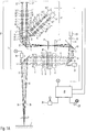
- Figure 1A 1 schematically shows an optical path through an arrangement of essential elements of an imaging system 26 of a microscopy system according to the first embodiment of the present invention, which is deployed in a plane.
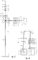
- the show FIGS. 1B, 1C and 1D schematically different views of essential elements of the imaging system of the microscopy system according to the preferred embodiment.
- Additional elements of the microscopy system are shown schematically in the form of block diagrams.
- the microscopy system according to the first preferred embodiment comprises an imaging optical system 26 which provides two pairs of imaging beam paths 2a, 2b and 2c, 2d.
- the imaging beam paths 2a and 2b and the imaging beam paths 2c and 2d respectively meet in pairs in the object plane 1.
- Main beams of the imaging beam paths 2a, 2b and 2c, 2d in each case enclose a stereo angle ⁇ in pairs.
- the microscopy system forms a stereomicroscope.
- the stereo angle ⁇ included in the object plane 1 by the first pair of imaging beam paths 2a, 2b may be different from the stereo angle (not shown in the figures) included in the object plane 1 by the second pair of imaging beam paths 2c, 2d.
- 2a, 2b and 2c, 2d paired stereo angles can also be the same size.
- the stereo angle ⁇ is between 4 ° and 6 °.
- the present invention is not limited to the above-mentioned angular range. Rather, it is sufficient if the stereo angle is not equal to zero degrees.
- the imaging beam paths 2a, 2b, 2c and 2d are designed to image an imaging field F in pairs in the object plane 1.
- the imaging field F indicates the finite (ie non-punctiform) region of an object to be examined (not shown) arranged in the object plane 1, which is imaged by the pairs of imaging beam paths 2a, 2b and 2c, 2d at a point in time (ie simultaneously).
- the size of the imaging field F depends on the size of the optical elements of the imaging system 26 and the magnification provided by the imaging system 26. In the example shown, the imaging field F has a diameter of between 10 mm and 100 mm. However, the present invention is not limited to a particular size of the imaging field F. It is only essential that the pairs of imaging beam paths 2a, 2b and 2c, 2d are designed to image a surface and not just a point in the object plane 1.
- the imaging system 26 is formed by a first optical subsystem T1 and a second optical subsystem T2, which subsystems T1 and T2 each have a plurality of optical elements.
- the first subsystem T1 has along a common optical axis K a first optical deflection element with a first optical mirror surface 3, a first, second, third, fourth and fifth optical lens 4, 5, 6, 7 and 8, a second optical deflection element with a second optical mirror surface 9, a third optical deflecting element having a third optical mirror surface 10, a sixth optical lens 11, a fourth optical deflecting element having a fourth optical mirror surface 12, a seventh and eighth optical lens 13 and 14 and prism parts 15 ', 15 "of a beam splitter assembly 15.
- the lenses 4, 5, 6, 7, 8, 11, 13 and 14 of the first subsystem T1 are penetrated jointly by the four imaging beam paths 2a, 2b, 2c and 2d. Furthermore, an afocal interface AF is arranged between the third and fourth optical lenses 6, 7, in which the imaging beam paths 2a, 2b, 2c and 2d are respectively imaged to infinity.
- the provision of the afocal interface AF allows for a modular construction of the imaging system 26. However, it is emphasized that the afocal interface AF is not required to implement the invention.
- the imaging beam paths 2a, 2b, 2c and 2d are successively reflected on the first mirror surface 3, the second mirror surface 9, the third mirror surface 10 and the fourth mirror surface 12 and deflected.
- FIG. 1D includes normal vectors of the plane defined by the first mirror surface 3 and the fourth mirror surface 12 planes relative to each other a variable angle of between 70 ° and 110 °.
- normal vectors of the planes subtended by the second mirror surface 9 and the third mirror surface 10, respectively, relative to each other include a variable angle of between 70 ° and 110 °.
- the present invention is not limited to such an angular range.
- Normal vectors of the planes spanned by the third mirror surface 10 and the fourth mirror surface 12 include a constant angle of substantially 60 ° relative to each other.
- the term "essentially 60 °" means a deviation of 60 ° by at most 5 ° and preferably at most 2 ° and particularly preferably at most 1 °.
- This arrangement of the first to fourth mirror surfaces 3, 9, 10 and 12 acts optically in total like a Porro system of the second kind. That is, the first to fourth mirror surfaces 3, 9, 10 and 12 cause both image reversal and pupil interchange. Next is through this arrangement of the mirror surfaces 3, 9, 10 and 12 achieves a particularly compact construction of the imaging system 26.
- the first to fifth lenses 4, 5, 6, 7 and 8 are arranged between the first deflecting element with the first mirror surface 3 and the second deflecting element with the second mirror surface 9.
- the sixth lens 11 is arranged between the third deflection element with the third mirror surface 10 and the fourth deflection element with the fourth mirror surface 12.
- the seventh and eighth lenses 13 and 14 are arranged between the fourth deflecting element with the fourth mirror surface 12 and the beam splitter assembly 15.
- the beam path between the second deflecting element with the second mirror surface 9 and the third deflecting element with the third mirror surface 10 is free of optical lenses.
- the first mirror surface 3 is arranged between the object plane 1 and the first lens 4 and thus between the object plane 1 and the first optically effective surface of the imaging system 26 along the imaging beam paths 2a, 2b, 2c and 2d.
- an optically active surface is understood as meaning a surface having a radius of curvature of at most 10 4 mm and preferably at most 5 * 10 3 mm and particularly preferably at most 10 3 mm.
- plane filters or cover plates should not be considered here as optically effective surface.
- the present invention is not limited to such an arrangement of the first mirror surface.
- the first effective surface of the imaging system may also be located between the first mirror surface and the object plane (not shown).
- the first deflecting element having the first mirror surface 3 is pivotable about a first pivot axis A.
- the first deflecting element is connected to a first drive 36.
- the first drive 36 is a stepper motor whose motor axis directly forms the first pivot axis A, which carries the first deflecting element having the first mirror surface 9.
- FIG. 1D leads a pivoting of the first mirror surface 3 by means of the first drive 37 about the first pivot axis A to a translational displacement of the imaging field F of the imaging system 26 in the object plane 1 in the X direction.
- FIG. 1D the first pivot axis A in a region in which the optical axis K meets the first mirror surface 3. This is in FIG. 1D in the middle of the first mirror surface 3.
- the second deflecting element having the second mirror surface 9 is pivotable about a second pivot axis B, which second pivot axis B is different from the first pivot axis A.
- the second deflecting element is connected to a second drive 37, which is formed in the embodiment shown by a stepping motor, the motor axis carries the second deflecting element and the second pivot axis B determines.
- FIG. 1D a pivoting of the second mirror surface 9 by means of the second drive 38 to a translational displacement of the imaging field F of the imaging system 26 in the object plane 1 in the Y direction.
- FIG. 1D the second pivot axis B in a region in which the optical axis K meets the second mirror surface 9. This is in FIG. 1D in the middle of the second mirror surface 9.
- the first pivot axis A with a first deflection plane, which is spanned by the incident on the first mirror surface 3 and the first mirror surface 3 failing optical axis K of the imaging beam paths 2a, 2b, 2c, 2d closes an angle of substantially 90 °.
- the optical axis K is determined by the lenses 4 to 8, 11, 13, 14 of the first subsystem T1. It is obvious that the optical axis K in the first embodiment does not run along a single straight line but is bent by the mirror surfaces 3, 9, 10, 12.
- Next also includes the second pivot axis B with a second deflection plane, which is spanned by the incident on the second mirror surface 9 and incident from the second mirror surface 9 optical axis K of the imaging beam paths 2a, 2b, 2c, 2d, an angle of substantially 90 ° one.
- the optical axis K can also main rays of the imaging beam paths 2a to 2d are used as a reference.
- the main beams of the imaging beam paths 2a, 2b, 2c and 2d must lie in a common plane for this purpose.
- the second pivot axis B is arranged substantially parallel to the first deflection plane.
- the second pivot axis B is parallel to the first deflection plane, or that the second pivot axis B intersects the first deflection plane and encloses an angle of less than 5 ° and preferably less than 2 ° with the first deflection plane, or that the second pivot axis B and the first deflection plane coincide.
- the second pivot axis B lies in the first deflection plane.
- first and second deflecting elements and the first and second drives 36,37 so form a displacing means to drive the imaging field F of the imaging system 26 by driving the first and second drives 36,37 together and pivoting the first and second mirror surfaces 3,9 the object plane 1 to translate in any direction.
- the displacement by the optics of the imaging system 26 are limited since the imaging beam paths 2a, 2b, 2c, 2d may not be displaced outside the optical lenses 4, 5, 6, 7, 8 of the imaging system 26 penetrated by them.
- the first and second drives 36, 37 are each connected to a controller 28.
- the controller 28 is connected to user interfaces in the form of a joystick 29 and a microphone 29 '.
- control commands from a user for example in the form of speech and / or eye movement and / or foot movement and / or a Receive head movement and / or a hand movement of the user and output (preferably in digital form or in analog form) to the controller.
- the control commands can specify, for example, an absolute offset, and / or a relative offset and / or only one direction of an offset in conjunction with a time span.
- control device 28 determines a desired offset of the image field F in the object plane 1 and controls the first and second drives 36, 37 accordingly.
- the controller 28 can fall back on a table in which, depending on a respective total magnification of the microscopy system required for a desired offset angular positions of the first and second Mirror surface 3, 9 are stored.
- the controller may also use a corresponding conversion formula or directly control the first and second drives 36, 37 in response to a received command from a user.
- the optical lenses 4-8 of the first subsystem T1 are arranged along the common optical axis K.
- the first lens 4 relative to the second lens 5 and the third lens 6 relative to the fourth lens 7 along the optical axis K displaced to a distance of the object plane 1 of the imaging system 26 of the microscopy system and thus a working distance and / or a Magnification of the image of an object that can be arranged in the object plane 1.
- the second subsystem T2 of the imaging system 26 also has a multiplicity of optical elements 16 '- 22', 16 "- 22", 16 “'- 22"' and 16 “" - 22 "” in which the imaging beam paths 2a, 2b However, 2c and 2d, unlike the first subsystem T1, are each separately routed. This means that the optical lenses 16 '- 21', 16 "- 21", 16 '"- 21"' and 16 "" - 21 "” are interspersed in each case by an imaging beam path 2 a, 2 b, 2 c or 2 d.
- Each imaging beam path 2a and 2b of the second subsystem T2 has a stereoscopic view of the tube optics with the eyepieces 22 ', 22 "shown only schematically, for direct visual observation by a user.
- Each imaging beam path 2c and 2d of the second subsystem T2 has a camera adapter 22 "'and 22" "for a digital camera 31'” and 31 “” for generating image data.
- a stereo camera may also be used, and the cameras 31"' and 31 “” are connected to the controller 28, respectively.
- the controller 28 receives the image data respectively generated by the cameras 31 "', 31" "and automatically detects in the image data the position of a marker (not shown).
- the marker may, for example, also be a characteristic element of the object itself automatically identified in the image data, such as a surgical element (or instrument) imaged in the image data act specific body part of a patient.
- the control via the joystick 29 and / or the microphone 29 ' is switchable to an operating state in which the controller does not directly select a desired offset from a command received via the joystick 29 and / or the microphone 29', but indirectly based on in the Image data detected position of the marker determined.
- the controller 28 controls the first and second drives 36, 37 in response to the detected position of the marker.
- the controller 28 controls the first and second drives 36, 37 so that the detected position of the marker in the image data remains substantially constant.
- the controller pivots the first and second mirror surfaces 3, 9 by means of the first and second drives 36, 37 such that a marker detected, for example, in the center of the image data, even after a displacement of the marker relative to the object plane in the middle of the Image data remains.
- the term "substantially constant” should be understood to mean that the relative position of the marker in the image data does not change by more than 30% of a diameter of the imaging field F and preferably by not more than 10% of the diameter of the imaging field F.
- a physical beam splitter 15 is provided, which has a partially transparent mirror surface, which is penetrated by a first pair of imaging beam paths 2a and 2b and at which a second pair of imaging beam paths 2c and 2d reflected is.
- the microscopy system provides a secondary beam path 24, which passes through the third mirror surface 10 of the third deflection element in a central region.
- This central region may preferably lie between beam cross-sectional areas of the imaging beam paths 2a, 2b, 2c and 2d.
- the third mirror surface 10 at least partially a transparency for radiation of the secondary beam path 24, which is greater than a transparency for radiation of the imaging beam paths 2a, 2b, 2c, 2d.
- the coupling of the secondary beam path 24 can alternatively be done in a different way.
- the secondary beam path 24 is formed by an illumination optical unit 30 of an illumination system, wherein the illumination system further comprises a radiation source 23.
- This illumination system is not part of the imaging system 26.
- an infrared observation system (not shown) with infrared imaging optics and an infrared camera may be provided, the infrared imaging optics providing the secondary beam path 24.
- a laser may also be provided with a beam guidance system (not shown) which provides the secondary beam path 24.
- a beam guidance system (not shown) which provides the secondary beam path 24.
- the first, second, third and fourth deflecting elements are each an optical mirror.
- the deflecting elements may, for example, also be prisms, each having at least one mirror surface.
- the first, second, third and fourth deflecting elements can each optionally have a plurality of mirror surfaces for deflecting the imaging beam paths 2a, 2b, 2c and 2d. In addition, more or fewer than two pairs of imaging beam paths may be provided.
- the first, second, third and fourth mirror surfaces are arranged so that the common optical axis K of the first subsystem T1 is folded by the mirror surfaces so as to be in at least first and second planes to each other are substantially parallel, as well as in at least a third plane, which is substantially perpendicular to the two first and second planes, is located.
- the conditions of "substantially parallel” and “substantially perpendicular” should be considered fulfilled if the third plane, the two first and second planes each at an angle of between 60 ° and 120 ° and preferably between 80 ° and 100 ° and more preferably between 85 ° and 95 ° and in particular 90 °.
- the first plane through the incident on the first mirror surface 3 and optic axis K, the second plane through the incident on the fourth mirror surface 12 and optic axis K, and the third plane through which the second ( or third) mirror surface 9 (or 10) on and falling optical axis K spanned.
- the microscopy system according to the first preferred embodiment is particularly well suited for use as a surgical microscope.
- the reason is that by pivoting the first and second mirror surfaces 3, 9 in a particularly simple, fast, reliable and vibration-free manner, it is possible for a user to displace the imaging field F in the object plane 1.
- the controller 28 may effect automatic image stabilization and image tracking by exposing the first and second mirror surfaces 3, 9 automatically in response to the position of the marker detected in image data.
- FIGS. 1B to 1D For the sake of clarity, only one imaging beam path 2a was shown in each case. For the same reason, the imaging beam paths 2c and 2d are in Figure 1A not fully shown.
- FIGS. 1B, 1C and 1D omitted a representation of the illumination system and the optical axis K of the first subsystem T1.
- FIG. 1D schematically shows a perspective view in order (in contrast to the in Figure 1A deployed in a plane) to clarify the actual spatial arrangement of essential elements of the imaging system 26 of the microscopy system according to the first preferred embodiment.
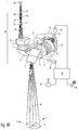
- FIG. 2 A second embodiment of a microscopy system according to the present invention is described. It shows FIG. 2 schematically a beam path through an unfolded in a plane arrangement of essential elements of an imaging system of the microscopy system. Additional elements of the microscopy system are shown schematically in the form of block diagrams. Since the structure of the microscopy system according to the second embodiment is similar in many parts to the structure of the micro copy system according to the first embodiment described in detail, only the differences between the first and second embodiments will be explained.
- a rotation of the created by the imaging system 26 image of the object plane 1 of the microscope system can be arranged object and thus the image field F is caused when the first and second axes of rotation A, B of the first and second mirror surface 3, 9 not each with a respective deflection plane, of the incident on the respective mirror surface 3, 9 and from the respective mirror surface 3, 9 failing optical axis K and / or main rays of the imaging beam paths 2a to 2d of first subsystem T1 is clamped, enclose an angle of substantially 90 °.
- the microscope system according to the second embodiment additionally comprises a compensation device, which causes an (additional) rotation of the image of the imaging field F produced by the imaging system 26.
- the adjustable prism arrangements 27' and 27" are connected to the controller 28 and each have at least one and preferably each have at least two mirror surfaces, which are rotatable relative to each other for optical rotation of the image provided by the imaging system 26.
- the present invention is not limited to such a construction of the optical compensation device.
- the controller 28 controls the adjustable prism assemblies 27 'and 27 "in response to control of the first and second drives 36, 37 such that rotation caused by pivoting of the first and second mirror surfaces 3, 9 is provided by the imaging system 26 Illustration of the object by one of the adjustable prism assemblies 27 ', 27 "caused opposing rotation of the image is canceled.
- the microscope system for compensating a rotation of the image of the object provided by the imaging system in the imaging beam paths 2c and 2d has a further compensation device in the form of an external graphics processor 27 *.
- the graphics processor 27 * is connected to the cameras 31 "'and 31""and to the controller 28.
- the controller 28 controls the graphics processor 27 * in response to a control of the first and second drives 36, 37 such that one by pivoting the first and second mirror surface 3, 9 rotation of the image provided by the imaging system 26 of the object is canceled by one of the graphics processor 27 * caused by electronic image processing rotation of the image with additional adjustment of the stereo base.
- the controller 28 takes into account both the degree of pivoting of the respective mirror surface 3, 9 and the orientation of the respective pivot axis A, B relative to the respectively deflected imaging beam path 2a, 2b, 2c and 2d or the optical axis K of the first subsystem T1.
- the compensation for example, by preferably controlled mechanical rotation of the camera pair 31 "', 31""done.
- the illumination beam path 24 'of the microscopy system according to the second embodiment is not deflected by the pivotable first and second mirror surfaces 3, 9.
- the microscopy system has an additional illumination mirror 38.
- the illumination mirror 38 deflects the illumination beam path 24 'and, in the embodiment shown, is pivotable about two mutually orthogonal axes by means of a third drive 39 in the form of a stepping motor, both in a plane spanned by the illumination mirror 38.
- the two axes of the illumination mirror 38 preferably intersect in a region in which the illumination beam path 24 'meets the illumination mirror 38.
- the third drive 39 is connected to the controller 28.
- the controller 28 controls the third drive 39 as a function of a control of the first and second drives 36, 37 so that the illumination mirror 38 is pivoted in a pivoting of the first and second mirror surfaces 3, 9 for the purpose of shifting the imaging field F in the object plane 1 in that the illumination beam path 24 'follows the displacement of the imaging field F.
- the illumination beam path 24 ' can alternatively be any secondary beam path for observing and / or influencing an object that can be arranged in the object plane 1.
- FIG. 3 shows an embodiment of a microscope system, which is not the subject of the claims. It shows FIG. 3 schematically a beam path through essential elements of the microscopy system, with additional elements of the microscopy system are shown schematically in the form of block diagrams.
- the microscopy system has an imaging system 26 * to image an object (not shown) disposed in an object plane 1.
- the imaging system 26 * (as in the first and second embodiments described above) consists of a first subsystem T1 * with a plurality of optical lenses 4 *, 5 * and 6 * in which imaging beam paths 2a *, 2b * are guided together, and a second subsystem T2 * with multiple optical lenses 16 '* - 20' *, 22 '*, 16' '* - 20 "*, 22" *, in which the imaging beam paths 2a *, 2b * are performed separately together.
- lenses of the first and second subsystems T1 *, T2 * can be displaced relative to one another in order to adapt a working distance or to change the magnification of the image. A more detailed description of these elements will be omitted.
- imaging beam paths 2a *, 2b * are provided which enclose a stereo angle ⁇ in the object plane and are supplied via eyepieces 22 '*, 22 "* to eyes 37' *, 37" * of a user.
- a separate mirror surface 3 * which is not part of the imaging system 26 *, is arranged between the imaging system 26 * and the object plane 1 *. The area between the mirror surface 3 * and the object plane 1 * is thus free of optically effective surfaces and / or elements.
- the mirror surface 3 * is connected to a drive 36 *, which is designed to pivot the mirror surface 3 * selectively about a pivot point P in an arbitrary direction.
- the pivot point P lies on an optical axis K of the first subsystem T1 * defined by the optical lenses 4 *, 5 * and 6 *.
- FIG. 3 is the pivot point P in the middle of the mirror surface 3 *.
- the second subsystem T2 * of in FIG. 3 shown imaging system 26 * for each imaging beam path 2a *, 2b * a compensation device 27 '*, 27 "* in the form of an adjustable prism arrangement.
- the controller 28 drives the drive 36 * to turn on (in FIG. 3 not shown) imaging field of the imaging system 26 * in the object plane 1 to move in any direction.
- the controller 28 automatically controls the drives of the compensation devices 27 '*, 27 "* so that the compensation devices 27' *, 27" * automatically compensate for an image rotation caused by a pivoting of the mirror surface 3 *.
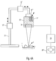
- FIG. 4A Fig. 12 schematically shows a side view of the structure of the microscopy system according to the second embodiment of the present invention.
- the microscopy system may further comprise a tripod 32 carrying a surgical microscope 33.
- the surgical microscope 33 comprises the imaging system 26, the compensation device 27 and the offset device 34 with each in the structure described in the second embodiment.
- About drives 32 ', 32 ", 32'” allows the tripod 32 a translational and rotational displacement of the surgical microscope 33 relative to the object plane.
- the controller 28 in FIG. 4A To input a desired offset of the imaging field relative to the object plane, the controller 28 in FIG. 4A a keyboard 29 '' on.
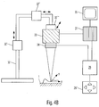
- FIG. 4B Fig. 12 is a schematic side view showing a structure of a microscopy system according to a fourth embodiment of the present invention.
- FIG. 4B shown fourth embodiment of the in FIG. 4A in particular in that the compensation device 27 and the offset device 34 are not included in the surgical microscope 33 but are separate modules that can be connected to the surgical microscope 33.
- the compensation device 27 is formed by a graphics processor which outputs a picture received by the operation microscope 33 and rotated in response to the control 28 and corrected for its stereo base via a monitor 35.
- the present invention is not limited thereto. Rather, any desired number of pivotable mirror surfaces can be provided in order to displace the imaging field of the imaging system in the object plane.
- the gift of the mirror surfaces for example, optionally be done by the respective mirror surface is pivoted by more than one pivot axis, or in that the respective mirror surface is rotated about an axis of rotation which includes a normal to the mirror surface non-zero angle. This axis of rotation can coincide with an incident on the respective mirror surface optical axis. Through such a rotation of Mirror surface is at the same time causes a pivoting of the mirror surface relative to the optical axis incident on the mirror surface, resulting in a displacement of the imaging field in the object plane.
- the present invention provides a microscopy system which, by pivoting at least one mirror surface, permits displacement of an imaging field of an imaging system of a microscopy system in an object plane in a particularly simple, reliable and vibration-free manner.
- a microscopy system which, by pivoting at least one mirror surface, permits displacement of an imaging field of an imaging system of a microscopy system in an object plane in a particularly simple, reliable and vibration-free manner.
- it is possible in a particularly convenient way by means of the microscopy system according to the invention to compensate for movements (and in particular also periodic movements) of a viewed object by corresponding displacement of the imaging field and thus to maintain a viewed object in the imaging field.
- the reason is that only one mirror surface must be pivoted and thus can be dispensed with a displacement of the entire imaging system of the microscopy system.
- the displacement may be controlled by a controller which determines a desired offset automatically or based on a user input.
- a rotation of the image of an object created by the imaging system which is possibly caused by a pivoting of the at least one mirror surface, can be corrected automatically by means of a compensation device.
- the controller controls the compensation device as a function of a measure and a direction of pivoting of the at least one mirror surface.
- Such a microscopy system is particularly suitable for use as a surgical microscope.
Description
Die vorliegende Erfindung betrifft ein Mikroskopiesystem zur Abbildung eines in einer Objektebene des Mikroskopiesystems anordenbaren Objekts.The present invention relates to a microscopy system for imaging an object that can be arranged in an object plane of the microscopy system.
Ein vibrationsfestes Mikroskop ist aus der
Das Mikroskopiesystem umfasst wenigstens ein Abbildungssystem, welches wenigstens einen Abbildungsstrahlengang zur Abbildung eines endlichen (d.h. nicht punktförmigen) Abbildungsfeldes der Objektebene bereitstellt, sowie eine Versatzeinrichtung, welche ausgebildet ist, das Abbildungsfeld des Abbildungssystems in der Objektebene translatorisch zu verlagern.The microscopy system comprises at least one imaging system which provides at least one imaging beam path for imaging a finite (i.e., non-punctiform) imaging field of the object plane and a displacement device configured to translate the imaging field of the imaging system in the object plane.
Derartige Mikroskopiesysteme finden beispielsweise in der Medizintechnik als Operationsmikroskope Verwendung, um ein in einer Objektebene angeordnetes Objekt zu beobachten.Such microscopy systems are used, for example, in medical technology as surgical microscopes to observe an object arranged in an object plane.
Dabei wird das Operationsmikroskop üblicherweise von einem an einer Decke befestigten oder auf dem Boden stehenden Stativ getragen. Das Stativ dient als Versatzeinrichtung, um eine Positionierung des Operationsmikroskops über einem betrachteten Objekt zu erlauben. Hierfür erlaubt das Stativ üblicherweise eine translatorische Verlagerung des Abbildungssystems mit bis zu drei Freiheitsgraden (vor/zurück, links/rechts, oben/unten) sowie zumeist eine rotatorische Bewegung des Operationsmikroskops mit wenigstens einem Freiheitsgrad (Schwenkung gegenüber der Waagrechten).The surgical microscope is usually carried by a stand attached to a ceiling or standing on the ground tripod. The tripod serves as a shifter to allow positioning of the surgical microscope over a viewed object. For this, the tripod usually allows a translational displacement of the imaging system with up to three degrees of freedom (forward / backward, left / right, up / down) and usually a rotational movement of the surgical microscope with at least one degree of freedom (pivoting relative to the horizontal).
Derartige Stative sind relativ teuer, da sie einerseits in eingerastetem Zustand eine große Stabilität und Schwingungsfreiheit aufweisen und gleichzeitig leicht betätigbar sein müssen. Hierfür muss das Stativ ausreichend massiv ausgeführt sein, und das von ihm getragene Operationsmikroskop muss durch Federn oder Gegengewichte in möglichst jeder möglichen Stellung des Operationsmikroskops ausbalanciert sein. Weiter muss eine Positionierung mit hoher Genauigkeit möglich sein, da ein Abbildungsfeld (durch ein Abbildungssystem des Operationsmikroskops abgebildeter Bereich der Objektebene) des Operationsmikroskops insbesondere bei hoher Vergrößerung sehr klein ist.Such tripods are relatively expensive, since they have on the one hand in the locked state a great stability and freedom from vibration and at the same time must be easily operable. For this purpose, the tripod must be made sufficiently solid, and the surgical microscope worn by him must be balanced by springs or counterweights in any possible position of the surgical microscope. Furthermore, positioning must be possible with high accuracy since an imaging field (area of the object plane imaged by an imaging system of the surgical microscope) of the Surgical microscope is very small especially at high magnification.
Der vorstehend beschriebene Aufbau eines Mikroskopiesystems bestehend aus einem Operationsmikroskop und einem dieses tragenden Stativ aus dem Stand der Technik weist die folgenden Nachteile auf:The above-described construction of a microscopy system consisting of a surgical microscope and a prior art tripod carrying the same has the following disadvantages:
Aufgrund der großen Masse des Operationsmikroskops und des Stativs ist es in Folge der zu beschleunigenden bzw. abzubremsenden trägen Massen auch bei optimal ausbalanciertem Stativ nur schwer möglich, kleinen Bewegungen eines betrachteten Objektes durch Verlagerung des Operationsmikroskops zu folgen oder Feineinstellungen in der Positionierung des Operationsmikroskops vorzunehmen.Due to the large mass of the surgical microscope and the tripod, it is difficult to follow small movements of a subject by displacing the surgical microscope or make fine adjustments in the positioning of the surgical microscope as a result of the inertia to be accelerated or braked even with optimally balanced tripod.
Weiter ist die Betätigung eines herkömmlichen Stativs auch bei einer optimalen Ausbalancierung körperlich anstrengend, wenn viele kleine Positionierungen vorgenommen werden müssen. Hierzu trägt die Tatsache bei, dass es eine neue Positionierung des Operationsmikroskops in der Regel erforderlich macht, dass der Benutzer direkt oder mittelbar über eine Steuerung mit seinen Händen tätig wird und somit seine Arbeit unterbrechen muss.Further, the operation of a conventional tripod is physically strenuous even with an optimal balance when many small positions must be made. This is helped by the fact that a new positioning of the surgical microscope usually requires the user to act directly or indirectly via a control with his hands and thus to interrupt his work.
Zur Lösung dieser Probleme ist aus der
Diese Verlagerungseinrichtung weist allerdings den Nachteil auf, dass sie technisch aufwendig ist und aufgrund ihres Eigengewichts ein vergleichsweise aufwendigeres und stabileres Stativ notwendig macht. Weiter ist für eine Verlagerung des Operationsmikroskops immer noch eine Beschleunigung der trägen Masse des Operationsmikroskops erforderlich. Die träge Masse des Operationsmikroskops verhindert zum einen eine schnelle Verlagerung. Zum anderen besteht bei einer schnellen positiven oder negativen Beschleunigung der trägen Masse des Operationsmikroskops die Gefahr, dass Schwingungen erzeugt und auf das Stativ übertragen werden. Zudem ist es bei direkter visueller Beobachtung nach einer Verlagerung des Operationsmikroskops erforderlich, dass der Benutzer seine Arbeitsposition zumindest geringfügig anpasst.However, this displacement device has the disadvantage that it is technically complex and, due to its own weight, makes a comparatively more elaborate and more stable tripod necessary. Furthermore, an acceleration of the inertial mass of the surgical microscope is still required for a displacement of the surgical microscope. The inert mass of the Surgical microscope prevents for a quick shift. On the other hand there is a risk that vibrations are generated and transmitted to the tripod with a rapid positive or negative acceleration of the inertial mass of the surgical microscope. In addition, direct visual observation after a surgical microscope shift requires that the user at least slightly adjust his working position.
Aufgrund der vorstehend beschriebenen Nachteile des Standes der Technik ist es derzeit praktisch nicht möglich, kleine, schnelle und insbesondere periodische Verlagerungen des Operationsmikroskops durchzuführen, um auf beispielsweise durch die Atmung eines Patienten hervorgerufene Verlagerungen eines betrachteten Objektes in der Objektebene zu reagieren.Due to the disadvantages of the prior art described above, it is currently practically not possible to perform small, fast and in particular periodic displacements of the surgical microscope in order to respond to, for example, caused by the respiration of a patient displacements of a viewed object in the object plane.
Das Dokument
Das Dokument
Das Dokument
Ausgehend hiervon ist es eine Aufgabe der vorliegenden Erfindung, ein Mikroskopiesystem bereitzustellen, welches eine Verlagerung eines Abbildungsfeldes der Objektebene auf besonders einfache, schnelle, zuverlässige und vibrationsfreie Weise ermöglicht. Weiter ist es eine Aufgabe der vorliegenden Erfindung, ein Verfahren bereitzustellen, welches eine Verlagerung des Abbildungsfeldes der Objektebene eines Stereo-Mikroskopiesystem auf besonders einfache, schnelle, zuverlässige und vibrationsfreie Weise ermöglicht.Based on this, it is an object of the present invention to provide a microscopy system which allows a displacement of an imaging field of the object plane in a particularly simple, fast, reliable and vibration-free manner. Further, it is an object of the present invention to provide a method which allows a displacement of the imaging field of the object plane of a stereo microscope system in a particularly simple, fast, reliable and vibration-free manner.
Die vorstehende Aufgabe wird durch ein Mikroskopiesystem mit der Kombination der Merkmale der unabhängigen Ansprüche 1 und 5 gelöst. Vorteilhafte Weiterbildungen finden sich in den Unteransprüchen.The above object is achieved by a microscopy system with the combination of the features of
Gemäß einer ersten bevorzugten Ausführungsform umfasst ein Mikroskopiesystem zur Abbildung eines in einer Objektebene des Mikroskopiesystems anordenbaren Objekts ein Abbildungssystem, eine Versatzeinrichtung und eine Steuerung. Das Abbildungssystem stellt wenigstens einen Abbildungsstrahlengang zur Abbildung eines Abbildungsfeldes der Objektebene bereit. Dabei wird unter Abbildungsfeld der endliche (d.h. nicht punktförmige) Bereich der Objektebene verstanden, der zu einem Zeitpunkt von dem wenigstens einen Abbildungsstrahlengang des Abbildungssystems abgebildet werden kann. Das Abbildungsfeld wird im Stand der Technik häufig auch als Objektfeld bezeichnet. Die Versatzeinrichtung ist ausgebildet, das Abbildungsfeld des Abbildungssystems in der Objektebene translatorisch zu verlagern. Die Steuerung ist ausgebildet, einen gewünschten Versatz des Abbildungsfelds in der Objektebene zu ermitteln und die Versatzeinrichtung entsprechend zu steuern. Dabei weist die Versatzeinrichtung eine entlang des wenigstens einen Abbildungsstrahlengangs angeordnete erste Spiegelfläche zur Ablenkung des wenigstens einen Abbildungsstrahlengangs auf, welche erste Spiegelfläche in Abhängigkeit von dem durch die Steuerung ermittelten Versatz verschwenkbar ist.According to a first preferred embodiment, a microscope system for imaging an object that can be arranged in an object plane of the microscope system comprises an imaging system, a displacement device and a controller. The imaging system provides at least one imaging beam path for imaging an imaging field of the object plane. In this case, the term "imaging field" is understood to mean the finite (ie non-point-shaped) region of the object plane which can be imaged at a point in time by the at least one imaging beam path of the imaging system. The imaging field is often referred to in the art as an object field. The offset device is designed to be the imaging field of the Relocate imaging system in the object plane translational. The controller is designed to determine a desired offset of the imaging field in the object plane and to control the displacement device accordingly. In this case, the offset device has a first mirror surface arranged along the at least one imaging beam path for deflecting the at least one imaging beam path, which first mirror surface can be pivoted as a function of the offset determined by the control.
Somit erfolgt in der ersten Ausführungsform ein gewünschter, durch die Steuerung ermittelter Versatz des Abbildungsfeldes der Objektebene relativ zu der Objektebene durch Verschwenken einer den wenigstens einen Abbildungsstrahlengang des Abbildungssystem ablenkenden ersten Spiegelfläche. Dabei bezeichnet der Begriff "Spiegelfläche" in diesem Dokument allgemein die Reflexionsoberfläche eines optischen Umlenkelements.Thus, in the first embodiment, a desired offset of the imaging field of the object plane relative to the object plane determined by the control is achieved by pivoting a first mirror surface deflecting the at least one imaging beam path of the imaging system. The term "mirror surface" in this document generally refers to the reflection surface of an optical deflection element.
Dabei kann die Spiegelfläche beispielsweise frei oder um eine oder mehrere vorgegebene unterschiedliche Schwenkachsen verschwenkbar sein. Die Schwenkachsen können wahlweise außerhalb oder innerhalb der Spiegelfläche liegen. Auch können die Spiegelfläche und die Schwenkachsen wahlweise in der gleichen oder in unterschiedlichen Ebenen liegen. Gemäß einer Ausführungsform sind zwei zueinander orthogonale Schwenkachsen vorgesehen, die sich in einem Bereich der Spiegelfläche schneiden, an dem eine optische Achse eines auf die Spiegelfläche einfallenden Abbildungsstrahlengangs auf die Spiegelfläche trifft. Dieser Bereich kann in der Mitte der Spiegelfläche liegen. Die Schwenkachsen sind gedachte Achsen. Das bedeutet, dass die Spiegelfläche um diese gedachten Achsen herum gedreht wird, und bedeutet nicht, dass eine Welle, wie zum Beispiel ein Stab oder eine Stange, eingebaut sein muss.In this case, the mirror surface, for example, be free or pivotable about one or more predetermined different pivot axes. The pivot axes can optionally be outside or inside the mirror surface. Also, the mirror surface and the pivot axes can be located either in the same or in different planes. According to one embodiment, two mutually orthogonal pivot axes are provided, which intersect in a region of the mirror surface on which an optical axis of an incident on the mirror surface imaging beam path impinges on the mirror surface. This area can be in the middle of the mirror surface. The swivel axes are imaginary axes. This means that the mirror surface is rotated around these imaginary axes, and does not mean that a shaft, such as a rod or rod, must be installed.
Alternativ kann der Versatz des Abbildungsfeldes auch dadurch bewirkt werden, dass die Spiegelfläche um eine Drehachse rotiert wird, die im wesentlichen parallel zu einer von optischen Elementen (insbesondere optischen Linsen) des Abbildungssystems festgelegten optischen Achse des wenigstens einen von dem Abbildungssystem auf die Spiegelfläche einfallenden Abbildungsstrahlenganges ausgerichtet ist. Im Rahmen dieser Anmeldung wird unter einer Drehachse, die im wesentlichen parallel zu der optischen Achse ausgerichtet ist, verstanden, dass sich die jeweils von der Drehachse bzw. der optischen Achse und einer gemeinsamen Normalen aufgespannten Ebenen unter einem Winkel kleiner 20°, vorzugsweise kleiner 5° und besonders bevorzugt kleiner 2° schneiden. Dabei können die Drehachse und die optische Achse auch zusammenfallen. Anders gesagt kann die Spiegelfläche auch um eine Drehachse rotiert werden, die mit einer Normalen zur Spiegelfläche einen von Null verschiedenen Winkel einschließt. Durch eine derartige Rotation der Spiegelfläche wird gleichzeitig ein Verschwenken der Spiegelfläche relativ zu der optischen Achse des wenigstens einen von dem Abbildungssystem auf die Spiegelfläche einfallenden Abbildungsstrahlenganges bewirkt, was den Versatz des Abbildungsfeldes in der Objektebene zur Folge hat.Alternatively, the offset of the imaging field can also be effected by rotating the mirror surface about an axis of rotation which is substantially parallel to an optical axis of at least one of the optical system (in particular optical lenses) of the imaging system Imaging system is aligned on the mirror surface incident imaging beam path. In the context of this application is understood by a rotation axis, which is aligned substantially parallel to the optical axis, that the respectively spanned by the rotation axis or the optical axis and a common normal planes at an angle less than 20 °, preferably less than 5 ° and more preferably less than 2 ° cut. The axis of rotation and the optical axis can also coincide. In other words, the mirror surface can also be rotated about a rotation axis which encloses a non-zero angle with a normal to the mirror surface. Such a rotation of the mirror surface simultaneously causes a pivoting of the mirror surface relative to the optical axis of the at least one imaging beam path incident on the mirror surface by the imaging system, which results in the offset of the imaging field in the object plane.
Ein Verschwenken einer Spiegelfläche ist mit hoher Genauigkeit möglich. Da lediglich die träge Masse eines die Spiegelfläche bereitstellenden Umlenkelements (wie beispielsweise aber nicht abschließend eines optischen Spiegels oder Prismas) sowie eines ggf. vorhandenen Antriebs und/oder Getriebes, nicht jedoch die träge Masse des ganzen Abbildungssystems beschleunigt werden muss, sind auch kleine, schnelle und insbesondere periodische Verlagerungen des Abbildungsfeldes auf besonders einfache und zuverlässige Weise möglich. Dabei arbeitet die Versatzeinrichtung aufgrund der kleinen zu beschleunigenden trägen Masse auch bei starken Beschleunigungen nahezu vibrationsfrei.A pivoting of a mirror surface is possible with high accuracy. Since only the inertial mass of a deflection element providing the mirror surface (such as, but not limited to, an optical mirror or prism) and any existing drive and / or transmission, but not the inert mass of the entire imaging system has to be accelerated, even small, fast and in particular periodic displacements of the image field in a particularly simple and reliable manner possible. Due to the small inertial mass to be accelerated, the offset device works almost vibration-free even with strong accelerations.
Da für den gewünschten Versatz des Abbildungsfeldes lediglich die Spiegelfläche verschwenkt wird, das Abbildungssystem jedoch ortsfest bleibt, kann eine Arbeitsposition eines Benutzers nach dem Versatz des Abbildungsfeldes auch bei direkter visueller Beobachtung unverändert beibehalten werden.Since only the mirror surface is pivoted for the desired offset of the imaging field, but the imaging system remains stationary, a working position of a user after the offset of the imaging field can be maintained unchanged even with direct visual observation.
Bei einem Versatz, der beispielsweise weniger als ein Viertel und bevorzugt weniger als ein Achtel eines Arbeitsabstandes des Abbildungssystems von der Objektebene beträgt, erfolgt zudem weiterhin eine nahezu senkrechte Abbildung der Objektebene mittels des Abbildungssystems. Dabei wird jedoch betont, dass auch eine nicht senkrechte Betrachtung der Objektebene durch das Abbildungssystem in den meisten Fällen nicht schädlich ist und sogar gewünscht sein kann.For example, at an offset that is less than a quarter and preferably less than one eighth of a working distance of the Furthermore, a nearly vertical imaging of the object plane by means of the imaging system continues to take place. However, it is emphasized that even a non-perpendicular viewing of the object plane by the imaging system in most cases is not harmful and may even be desired.
Gemäß einer Ausführungsform kann die Versatzeinrichtung weiter eine entlang des wenigstens einen Abbildungsstrahlengangs angeordnete zweite Spiegelfläche zur Ablenkung des wenigstens einen Abbildungsstrahlengangs aufweisen, welche zweite Spiegelfläche in Abhängigkeit von dem durch die Steuerung ermittelten Versatz verschwenkbar ist. Dann kann die erste Spiegelfläche um eine erste Schwenkachse und die zweite Spiegelfläche um eine zweite Schwenkachse schwenkbar sein, welche zweite Schwenkachse von der ersten Schwenkachse verschieden ist.According to one embodiment, the offset device may further comprise a second mirror surface arranged along the at least one imaging beam path for deflecting the at least one imaging beam path, which second mirror surface is pivotable as a function of the offset determined by the control. Then, the first mirror surface may be pivotable about a first pivot axis and the second mirror surface about a second pivot axis, which second pivot axis is different from the first pivot axis.
Somit kann die Verlagerung des Abbildungsfeldes auch durch Verschwenken von zwei oder auch mehr Spiegelflächen, welche den wenigstens einen Abbildungsstrahlengang nacheinander ablenken, gemeinsam bewirkt werden. Dies kann Vorteile bringen, da ein Verschwenken einer Spiegelfläche um eine einzige vorgegebene Achse häufig einfacher und mit größerer Genauigkeit möglich ist, als eine freie Verschwenkung einer Spiegelfläche.Thus, the displacement of the imaging field can also be effected jointly by pivoting two or even more mirror surfaces, which deflect the at least one imaging beam path in succession. This can bring advantages, since a pivoting of a mirror surface about a single given axis is often easier and with greater accuracy possible, as a free pivoting of a mirror surface.
Dabei kann die erste Schwenkachse mit einer ersten Ablenkungsebene, die von einer auf die erste Spiegelfläche einfallenden und von der ersten Spiegelfläche ausfallenden optischen Achse des wenigstens einen Abbildungsstrahlengangs aufgespannt ist, einen Winkel von im wesentlichen 90° einschließen. Dabei ist die optische Achse von optischen Elementen (insbesondere optischen Linsen) des Abbildungssystems festgelegt. Weiter kann die zweite Schwenkachse mit einer zweiten Ablenkungsebene, die von der auf die zweite Spiegelfläche einfallenden und von der zweiten Spiegelfläche ausfallenden optischen Achse des wenigstens einen Abbildungsstrahlengangs aufgespannt ist, einen Winkel von im wesentlichen 90° einschließen und gleichzeitig zu der ersten Ablenkungsebene im wesentlichen parallel angeordnet sein.In this case, the first pivot axis with an initial deflection plane, which is spanned by an incident on the first mirror surface and incident from the first mirror surface optical axis of the at least one imaging beam path, include an angle of substantially 90 °. In this case, the optical axis of optical elements (in particular optical lenses) of the imaging system is fixed. Further, the second pivot axis with an second deflection plane, which is spanned by the incident on the second mirror surface and incident from the second mirror surface optical axis of the at least one imaging beam path, an angle of substantially 90 ° and at the same time be arranged substantially parallel to the first deflection plane.
Dabei wird in dieser Anmeldung unter "im wesentlichen 90°" eine Abweichung von 90° um höchstens 5° und bevorzugt höchstens 2° und besonders bevorzugt höchstens 1° verstanden. Weiter wird in dieser Anmeldung unter einer Schwenkachse, die zu einer Ablenkungsebene im wesentlichen parallel ist, verstanden, dass die Schwenkachse zu der Ablenkungsebene parallel ist oder dass die Schwenkachse die Ablenkungsebene schneidet und dabei mit der Ablenkungsebene einen Winkel von kleiner 5° und bevorzugt kleiner 2° einschließt. Weiter können die Schwenkachse und die Ablenkungsebene alternativ auch zusammenfallen.In this application, "substantially 90 °" in this application means a deviation of 90 ° by at most 5 ° and preferably at most 2 ° and particularly preferably at most 1 °. Furthermore, in this application, a pivot axis which is essentially parallel to a deflection plane is understood to mean that the pivot axis is parallel to the deflection plane or that the pivot axis intersects the deflection plane and thereby forms an angle of less than 5 ° and preferably less than 2 with the deflection plane ° includes. Further, the pivot axis and the deflection plane may alternatively coincide.
Gemäß einer Ausführungsform verlaufen die erste und zweite Schwenkachse jeweils in einem Bereich, in dem die auf die jeweilige erste und zweite Spiegelfläche einfallende optische Achse auf die jeweilige Spiegelfläche trifft. Dieser Bereich kann in der Mitte der jeweils zugehörigen ersten und zweiten Spiegelfläche liegen.According to one embodiment, the first and second pivot axes respectively extend in a region in which the optical axis incident on the respective first and second mirror surfaces impinges on the respective mirror surface. This area can lie in the middle of the respectively associated first and second mirror surface.
Diese Beziehung der ersten und zweiten Schwenkachse relativ zu dem wenigstens einen Abbildungsstrahlengang bzw. relativ zueinander weist den Vorteil auf, dass ein Verschwenken der ersten und zweiten Spiegelfläche um die Schwenkachsen neben der Verlagerung des Abbildungsfeldes relativ zur Objektebene keine bzw. nur eine vernachlässigbare Rotation der durch das Abbildungssystem erzeugten Abbildung des Abbildungsfelds hervorruft. Weiter wird so eine Translation des Abbildungsfeldes in der Objektebene in zwei Richtungen, die miteinander ebenfalls einen Winkel von im wesentlichen 90° einschließen, ermöglicht.This relationship of the first and second pivot axis relative to the at least one imaging beam path or relative to each other has the advantage that a pivoting of the first and second mirror surface about the pivot axes in addition to the displacement of the imaging field relative to the object plane no or only a negligible rotation of the imaging system causes generated imaging of the imaging field. Further, such a translation of the imaging field in the object plane in two directions, which also form an angle of substantially 90 ° with each other, allows.
Alternativ oder zusätzlich kann das Mikroskopiesystem weiter eine Kompensationseinrichtung umfassen, welche eine Rotation der durch das Abbildungssystem erzeugten Abbildung des Abbildungsfelds bewirkt. Dabei steuert die Steuerung die Kompensationseinrichtung in Abhängigkeit von einer Verschwenkung der ersten und/oder zweiten Spiegelfläche so, dass eine durch eine Verschwenkung der Spiegelflächen ggf. hervorgerufene Rotation der durch das Abbildungssystem bereitgestellten Abbildung des Abbildungsfelds durch eine von der Kompensationseinrichtung bewirkte Rotation der Abbildung wieder aufgehoben wird.Alternatively or additionally, the microscopy system may further comprise a compensation device, which causes a rotation of the imaging field generated by the imaging system. In this case, the controller controls the compensation device as a function of a pivoting of the first and / or second mirror surface such that a possibly caused by a pivoting of the mirror surfaces Rotation of the image system provided by the mapping of the imaging field is canceled by a caused by the compensation device rotation of the image again.
Dabei kann das Abbildungssystem wenigstens eine in dem wenigstens einen Abbildungsstrahlengang angeordnete Kamera zur Erzeugung von Bilddaten aufweisen und die Kompensationseinrichtung mit der wenigstens einen Kamera verbunden sein. Dann kann die Kompensationseinrichtung eine Rotation der von der wenigstens einen Kamera erzeugten Bilddaten durch elektronische Bildverarbeitung bewirken, um eine durch eine Verschwenkung der Spiegelflächen ggf. hervorgerufene Rotation der durch das Abbildungssystem bereitgestellten Abbildung des Abbildungsfelds auf besonders einfache Weise zu kompensieren.In this case, the imaging system can have at least one camera arranged in the at least one imaging beam path for generating image data, and the compensation device can be connected to the at least one camera. The compensation device can then effect a rotation of the image data generated by the at least one camera by electronic image processing in order to compensate in a particularly simple manner for a rotation of the image of the imaging field provided by the imaging system as a result of a pivoting of the mirror surfaces.
Alternativ oder zusätzlich kann die Kompensationseinrichtung wenigstens eine in dem wenigstens einen Abbildungsstrahlengang angeordnete und durch die Steuerung einstellbare Prisma-Anordnung aufweisen. Dabei ist die Prisma-Anordnung bevorzugt ausgebildet, bei einer Verdrehung des Prismas eine Bilddrehung um die von optischen Elementen des Abbildungssystems festgelegte optische Achse als Drehachse zu bewirken.Alternatively or additionally, the compensation device may have at least one prism arrangement arranged in the at least one imaging beam path and adjustable by the control. In this case, the prism arrangement is preferably designed to effect an image rotation about the optical axis of the imaging system defined optical axis as a rotation axis in a rotation of the prism.
Gemäß einer zweiten bevorzugten Ausführungsform, die mit der vorangegangenen ersten bevorzugten Ausführungsform auch kombiniert werden kann, umfasst ein Mikroskopiesystem zur Abbildung eines in einer Objektebene des Mikroskopiesystems anordenbaren Objekts ein Abbildungssystem, welches wenigstens einen Abbildungsstrahlengang zur Abbildung eines Abbildungsfeldes der Objektebene bereitstellt, sowie eine Versatzeinrichtung, welche ausgebildet ist, das Abbildungsfeld des Abbildungssystems in der Objektebene translatorisch zu verlagern. Dabei weist die Versatzeinrichtung wenigstens ein Paar von entlang des wenigstens einen Abbildungsstrahlengangs angeordneten ersten und zweiten Spiegelflächen zur Ablenkung des wenigstens einen Abbildungsstrahlengangs auf. Dabei ist das wenigstens eine Paar von Abbildungsstrahlengängen nacheinander an der ersten und der zweiten Spiegelfläche reflektiert. Weiter ist die erste Spiegelfläche um eine erste Schwenkachse verschwenkbar, welche erste Schwenkachse mit einer ersten Ablenkungsebene, die von einer auf die erste Spiegelfläche einfallenden und von der ersten Spiegelfläche ausfallenden optischen Achse des wenigstens einen Abbildungsstrahlengangs aufgespannt ist, einen Winkel von im wesentlichen 90° einschließt. Dabei ist die optische Achse durch optische Elemente (insbesondere optische Linsen) des Abbildungssystems festgelegt. Zudem ist die zweite Spiegelfläche um eine zweite Schwenkachse verschwenkbar, welche zweite Schwenkachse mit einer zweiten Ablenkungsebene, die von der auf die zweite Spiegelfläche einfallenden und von der zweiten Spiegelfläche ausfallenden optischen Achse des wenigstens einen Abbildungsstrahlengangs aufgespannt ist, einen Winkel von im wesentlichen 90° einschließt. Zudem ist die zweite Schwenkachse zu der ersten Ablenkungsebene im wesentlichen parallel angeordnet. Dabei kann die zweite Schwenkachse auch in der ersten Ablenkungsebene liegen.According to a second preferred embodiment, which can also be combined with the preceding first preferred embodiment, a microscopy system for imaging an object that can be arranged in an object plane of the microscopy system comprises an imaging system which provides at least one imaging beam path for imaging an imaging field of the object plane, and a displacement device, which is designed to translate the imaging field of the imaging system in the object plane. In this case, the offset device has at least one pair of first and second mirror surfaces arranged along the at least one imaging beam path for deflecting the at least one imaging beam path. In this case, the at least one pair of imaging beam paths is successively reflected at the first and the second mirror surface. Further the first mirror surface is pivotable about a first pivot axis, which first pivot axis with a first deflection plane, which is spanned by an incident on the first mirror surface and incident from the first mirror surface optical axis of the at least one imaging beam path, an angle of substantially 90 °. In this case, the optical axis is defined by optical elements (in particular optical lenses) of the imaging system. In addition, the second mirror surface is pivotable about a second pivot axis, which second pivot axis with an second deflection plane, which is spanned by the incident on the second mirror surface and incident from the second mirror surface optical axis of the at least one imaging beam path, forms an angle of substantially 90 ° , In addition, the second pivot axis is arranged substantially parallel to the first deflection plane. In this case, the second pivot axis can also lie in the first deflection plane.
Durch Verschwenken der ersten und/oder zweiten Spiegelfläche um die erste und/oder zweite Schwenkachse kann so eine translatorische Verlagerung des Abbildungsfeldes in der Objektebene in zwei Richtungen, welche miteinander einen Winkel von im wesentlichen 90° einschließen, bewirkt werden. Dabei führt die genannte Orientierung der ersten und zweiten Schwenkachse relativ zu dem wenigstens einen Abbildungsstrahlengang dazu, dass ein Verschwenken der Spiegelflächen keine bzw. nur eine vernachlässigbare Rotation der durch das Abbildungssystem erzeugten Abbildung des Abbildungsfelds hervorruft.By pivoting the first and / or second mirror surface about the first and / or second pivot axis, a translational displacement of the imaging field in the object plane in two directions, which together form an angle of substantially 90 °, can be effected. The said orientation of the first and second pivot axes relative to the at least one imaging beam path results in pivoting of the mirror surfaces causing no or only negligible rotation of the image of the imaging field generated by the imaging system.
Wie bei der ersten bevorzugten Ausführungsform kann das Mikroskopiesystem weiter eine Steuerung aufweisen, welche ausgebildet ist, einen gewünschten Versatz des Abbildungsfelds in der Objektebene zu ermitteln und die erste und zweite Spiegelfläche in Abhängigkeit von dem ermittelten Versatz um die jeweilige erste bzw. zweite Schwenkachse zu verschwenken.As with the first preferred embodiment, the microscopy system may further include a controller configured to determine a desired offset of the imaging field in the object plane and to pivot the first and second mirror surfaces about the respective first and second pivot axes, respectively, in response to the determined offset ,
Allgemein kann das Abbildungssystem wenigstens eine in dem wenigstens einen Abbildungsstrahlengang angeordnete Kamera zur Erzeugung von Bilddaten aufweisen und die Steuerung mit der wenigstens einen Kamera verbunden und weiter ausgebildet sein, in den Bilddaten automatisch die Position eines Markers zu detektieren und den ersten und/oder zweiten Antrieb automatisch in Abhängigkeit von der detektierten Position des Markers zu steuern.In general, the imaging system can have at least one camera arranged in the at least one imaging beam path for generating image data, and the controller can be connected to the at least one camera and be further configured to automatically detect the position of a marker in the image data and the first and / or second drive automatically depending on the detected position of the marker to control.
Dabei kann es sich bei dem Marker beispielsweise um ein separates, in der Objektebene eigens angeordnetes Element (z.B. ein charakteristisch ausgebildeter Aufkleber) oder aber auch um ein in den Bilddaten automatisch identifiziertes charakteristisches Element des Objektes selber (wie z.B. ein in den Bilddaten abgebildetes chirurgisches Element / Instrument oder ein bestimmtes Körperteil eines Patienten wie z.B. ein Zahn oder ein Organ) handeln.In this case, the marker may be, for example, a separate element arranged in the object plane (eg a characteristically formed sticker) or else a characteristic element of the object itself (such as a surgical element depicted in the image data) Instrument or a particular body part of a patient such as a tooth or organ).
Dabei kann es wünschenswert sein, wenn die Steuerung ausgebildet ist, den ersten und/oder zweiten Antrieb automatisch so zu steuern, dass die Position des Markers in den Bilddaten im wesentlichen konstant bleibt.In this case, it may be desirable if the controller is designed to automatically control the first and / or second drive in such a way that the position of the marker in the image data remains substantially constant.
Hierdurch ist beispielsweise eine (auch automatische) Bildstabilisierung oder ein (auch automatisches) Nachverfolgen der Bewegung eines betrachteten Objektes möglich. Die Bildstabilisierung ist insbesondere dann wünschenswert, wenn ein betrachtetes Objekt (beispielsweise in Folge von Atmung eines Patienten) periodische Lageveränderungen aufweist. Bei der Nachverfolgung der Bewegung eines Objektes ist es beispielsweise möglich, der Bewegung eines chirurgischen Instrumentes zu folgen und das chirurgische Instrument immer in der Mitte des Abbildungsfeldes zu halten.In this way, for example, an (even automatic) image stabilization or a (also automatic) tracking of the movement of a viewed object is possible. Image stabilization is particularly desirable when a viewed object (for example, as a result of respiration of a patient) has periodic positional changes. When tracking the movement of an object, it is possible, for example, to follow the movement of a surgical instrument and to always keep the surgical instrument in the center of the imaging field.
Weiter oder alternativ kann die Steuerung auch eine Benutzerschnittstelle wie beispielsweise eine Tastatur, ein Fußpedal, einen Joystick, eine Sprachsteuerung etc. aufweisen, und den gewünschten Versatz des Abbildungsfelds in der Objektebene in Abhängigkeit von einem über die Benutzerschnittstelle empfangenen Steuerbefehl ermitteln.Further or alternatively, the controller may also include a user interface such as a keyboard, a foot pedal, a joystick, a voice control, etc., and the desired offset of the imaging field in the Determine the object level as a function of a control command received via the user interface.
Dabei kann durch einen Benutzer über die Benutzerschnittstelle beispielsweise ein absoluter Versatz (z.B. in Form von Zielkoordinaten), ein relativer Versatz (z.B. in Form eines von der aktuellen Mitte der Abbildung ausgehenden Versatzvektors) und/oder lediglich eine Richtung eines Versatzes in Verbindung mit einer Zeitspanne (z.B. Halten eines Joysticks in eine gewünschte Richtung bis ein gewünschter Versatz erreicht ist) eingegeben werden.In this case, for example, an absolute offset (eg in the form of target coordinates), a relative offset (eg in the form of an offset vector emanating from the current center of the image) by a user via the user interface and / or only one direction of an offset in conjunction with a time span (eg, holding a joystick in a desired direction until a desired offset is reached).
Dabei kann die Benutzerschnittstelle weiter ausgebildet sein, um Steuerbefehle von einem Benutzer in Form von Sprache und/oder einer Augenbewegung und/oder einer Fußbewegung und/oder einer Kopfbewegung und/oder einer Handbewegung des Benutzers zu empfangen und (in digitaler oder analoger Form) an die Steuerung auszugeben.In this case, the user interface can be further configured to receive control commands from a user in the form of speech and / or eye movement and / or foot movement and / or head movement and / or hand movement of the user (in digital or analog form) to issue the control.
Allgemein kann das Abbildungssystem eine Mehrzahl von optischen Linsen umfassen. Gemäß einer Ausführungsform ist dann zwischen der ersten und der zweiten Spiegelfläche wenigstens eine optische Linse des Abbildungssystems angeordnet.Generally, the imaging system may include a plurality of optical lenses. According to one embodiment, at least one optical lens of the imaging system is then arranged between the first and the second mirror surface.
Um durch mehrfache Faltung des wenigstens einen Abbildungsstrahlenganges einen möglichst kompakten Aufbau des Mikroskopiesystems zu erzielen, kann das Abbildungssystem zur Ablenkung des wenigstens einen Abbildungsstrahlengangs weiter eine dritte Spiegelfläche und eine vierte Spiegelfläche aufweisen. Dann kann der wenigstens eine Abbildungsstrahlengang nacheinander an der ersten Spiegelfläche, der zweiten Spiegelfläche, der dritten Spiegelfläche und der vierten Spiegelfläche reflektiert sein.In order to achieve as compact a structure of the microscope system as possible by folding the at least one imaging beam path multiple times, the imaging system for deflecting the at least one imaging beam path may further comprise a third mirror surface and a fourth mirror surface. Then, the at least one imaging beam path can be successively reflected on the first mirror surface, the second mirror surface, the third mirror surface and the fourth mirror surface.
Dabei kann es vorteilhaft sein, wenn die erste Spiegelfläche und die vierte Spiegelfläche relativ zueinander einen Winkel von zwischen 60° und 120° und bevorzugt zwischen 80° und 100° einschließen, sowie die zweite Spiegelfläche und die dritte Spiegelfläche relativ zueinander einen Winkel von zwischen 60° und 120° und bevorzugt zwischen 80° und 100° einschließen. Weiter können die dritte Spiegelfläche und die vierte Spiegelfläche relativ zueinander einen Winkel von im wesentlichen 60° einschließen. Der Grund ist, dass unter diesem Winkel angeordnete Spiegelflächen insgesamt wie ein Porro-System zweiter Art wirken. Folglich heben sich durch die Ablenkungen des wenigstens einen Abbildungsstrahlenganges an den Spiegelflächen hervorgerufene Seitenvertauschungen der Abbildung gegenseitig auf. Weiter ist eine durch die Ablenkungen der Abbildungsstrahlengänge insgesamt hervorgerufene Bildrotation gering bzw. nicht vorhanden.It may be advantageous if the first mirror surface and the fourth mirror surface relative to each other include an angle of between 60 ° and 120 ° and preferably between 80 ° and 100 °, and the second mirror surface and the third mirror surface relative to each other an angle of between 60 ° and 120 ° and preferably between 80 ° and 100 °. Further, the third mirror surface and the fourth mirror surface may include an angle of substantially 60 ° relative to each other. The reason is that at this angle arranged mirror surfaces act as a total Porro system of the second kind. Consequently, side deflections of the image caused by the deflections of the at least one imaging beam path at the mirror surfaces cancel each other out. Further, image rotation caused by the deflections of the imaging beam paths as a whole is small or absent.
Gemäß einer Ausführungsform wird bei einer derartigen Anordnung der ersten bis vierten Spiegelfläche der wenigstens eine Abbildungsstrahlengang so geführt, dass optische Achsen des wenigstens einen Abbildungsstrahlengangs in wenigstens einer ersten und zweiten Ebene verlaufen, die zueinander im wesentlichen parallel sind, sowie in wenigstens einer dritten Ebene verlaufen, welche zu den beiden ersten und zweiten Ebenen im wesentlichen senkrecht ist. Dabei soll die Bedingung von "im wesentlichen parallel" und "im wesentlichen senkrecht" als erfüllt angesehen werden, wenn die dritte Ebene die beiden ersten und zweiten Ebenen jeweils unter einem Winkel von zwischen 60° und 120° und bevorzugt zwischen 80° und 100° und besonders bevorzugt zwischen 85° und 95° und insbesondere 90° schneidet. Im vorliegenden Fall wird die erste Ebene durch optische Achsen von auf die erste Spiegelfläche ein- und ausfallenden Abbildungsstrahlenbündel des wenigstens einen Abbildungsstrahlenganges, die zweite Ebene durch optische Achsen der auf die vierte Spiegelfläche ein- und ausfallenden Abbildungsstrahlenbündel des wenigstens einen Abbildungsstrahlenganges, und die dritte Ebene durch optischen Achsen der auf die zweite (oder dritte) Spiegelfläche ein- und ausfallenden Abbildungsstrahlenbündel des wenigstens einen Abbildungsstrahlenganges aufgespannt.According to one embodiment, in such an arrangement of the first to fourth mirror surface, the at least one imaging beam path is guided such that optical axes of the at least one imaging beam path extend in at least a first and second plane which are substantially parallel to each other and extend in at least a third plane which is substantially perpendicular to the first and second planes. In this case, the condition of "substantially parallel" and "substantially perpendicular" should be considered fulfilled if the third plane, the two first and second planes each at an angle of between 60 ° and 120 ° and preferably between 80 ° and 100 ° and more preferably between 85 ° and 95 ° and in particular 90 °. In the present case, the first plane is formed by optical axes of imaging beams of the at least one imaging beam path incident on and off the first mirror surface, the second plane by optical axes of the imaging beams of the at least one imaging beam path entering and leaving the fourth mirror surface, and the third plane spanned by optical axes of the second (or third) mirror surface incident and falling imaging beam of at least one imaging beam path.
Dabei kann der wenigstens eine Abbildungsstrahlengang zwischen der zweiten Spiegelfläche und der dritten Spiegelfläche frei von optischen Linsen sein.In this case, the at least one imaging beam path between the second mirror surface and the third mirror surface can be free from optical lenses.
Gemäß einer Ausführungsform kann der wenigstens eine Abbildungsstrahlengang auch an mehr oder weniger als vier Spiegelflächen abgelenkt sein, wobei die Spiegelflächen wechselseitig beliebige Winkel einschließen können. Eine dann auftretende Seitenvertauschung, Verzerrung oder Rotation der Abbildung kann dann durch eine entsprechende Korrektureinrichtung wahlweise optisch oder digital korrigiert werden.According to one embodiment, the at least one imaging beam path can also be deflected at more or less than four mirror surfaces, wherein the mirror surfaces can mutually enclose any desired angles. A then occurring page interchanging, distortion or rotation of the image can then be corrected optically or digitally by a corresponding correction device.
Gemäß einer Ausführungsform weist das Mikroskopiesystem weiter einen zweiten Antrieb auf, welcher die zweite Spiegelfläche wahlweise um die zweite Schwenkachse verschwenkt. Zusätzlich oder alternativ kann das Mikroskopiesystem weiter einen ersten Antrieb aufweisen, welcher die erste Spiegelfläche wahlweise um die erste Schwenkachse verschwenkt. Dann ist die Steuerung bevorzugt ausgebildet, den ersten und/oder zweiten Antrieb zu steuern.According to one embodiment, the microscopy system further comprises a second drive, which optionally pivots the second mirror surface about the second pivot axis. Additionally or alternatively, the microscopy system may further comprise a first drive, which optionally pivots the first mirror surface about the first pivot axis. Then, the controller is preferably designed to control the first and / or second drive.
Es kann Vorteile bringen, wenn die erste Spiegelfläche zwischen der Objektebene und einer entlang des wenigstens einen Abbildungsstrahlengangs ersten optisch wirksamen Oberfläche des Abbildungssystems angeordnet ist. Der Grund ist, dass der abgelenkte Abbildungsstrahlengang dann z.B. keine optischen Linsen mehr durchlaufen muss, was bei einer großen Verkippung der ersten Spiegelfläche ggf. große optische Linsen erforderlich machen kann. Dabei wird unter einer optisch wirksamen Oberfläche eine Oberfläche mit einem Krümmungsradius von höchstens 104 mm und bevorzugt höchstens 5*103 mm und besonders bevorzugt höchstens 103 mm verstanden. Somit sollen z.B. plane Filter oder Abdeckscheiben, die in den erfindungsgemäßen Mikroskopiesystem Verwendung finden können, hier nicht als optisch wirksame Oberfläche gelten.It can bring advantages if the first mirror surface is arranged between the object plane and a first optically active surface of the imaging system along the at least one imaging beam path. The reason is that the deflected imaging beam path then no longer has to go through optical lenses, for example, which may necessitate large optical lenses if there is a large tilt of the first mirror surface. In this case, an optically active surface is understood as meaning a surface having a radius of curvature of at most 10 4 mm and preferably at most 5 * 10 3 mm and particularly preferably at most 10 3 mm. Thus, for example, plane filters or cover plates, which can be used in the microscopy system according to the invention, are not considered as an optically effective surface here.
Gemäß einer Ausführungsform ist der Abbildungsstrahlengang zwischen der ersten Spiegelfläche und der Objektebene frei von optisch wirksamen Elementen. Dabei werden unter optisch wirksamen Elementen derartige Elemente verstanden, durch deren Hinzufügen oder Entfernen ein Arbeitsabstand des Mikroskopiesystems um mehr als 0,5% und insbesondere mehr als 1% und weiter insbesondere um mehr als 2% und weiter insbesondere um mehr als 5% verändert wird. Filter oder Abdeckscheiben werden in diesem Zusammenhang nicht als optisch wirksame Elemente gesehen.According to one embodiment, the imaging beam path between the first mirror surface and the object plane is free of optically active elements. Here, optically active elements are understood to be elements of which, by adding or removing them, a working distance of the Microscopy system is changed by more than 0.5% and in particular more than 1% and more particularly more than 2% and more particularly more than 5%. Filters or covers are not seen in this context as optically active elements.
Allgemein kann das Mikroskopiesystem als Stereo-Mikroskopiesystem ausgebildet sein, bei dem das Abbildungssystem wenigstens ein Paar von Abbildungsstrahlengängen bereitstellt, die in der Objektebene einen Stereowinkel einschließen. Dann kann das Abbildungssystem ein erstes Teilsystem aufweisen, das eine Mehrzahl von Linsen umfasst, welche entlang einer gemeinsamen optischen Achse angeordnet und von beiden Abbildungsstrahlengängen des wenigstens einen Paars von Abbildungsstrahlengängen gemeinsam durchsetzt sind.In general, the microscopy system can be embodied as a stereo microscopy system, in which the imaging system provides at least one pair of imaging beam paths, which include a stereo angle in the object plane. Then, the imaging system may comprise a first subsystem comprising a plurality of lenses arranged along a common optical axis and interspersed in common by both imaging beam paths of the at least one pair of imaging beam paths.
Weiter kann die erste und/oder zweite Spiegelfläche entlang der optischen Achse des ersten Teilsystems zwischen optischen Linsen des ersten Teilsystems angeordnet sein. Diese Anordnung der Spiegelflächen im ersten Teilsystem erleichtert es aufgrund der Verwendung von vergleichsweise großen gemeinsamen optischen Linsen für alle Abbildungsstrahlengänge, sicherzustellen, dass die Abbildungsstrahlengänge auch nach einem Verschwenken der Spiegelflächen noch durch die optischen Linsen hindurchgefädelt werden.Furthermore, the first and / or second mirror surface may be arranged along the optical axis of the first subsystem between optical lenses of the first subsystem. Due to the use of comparatively large common optical lenses for all imaging beam paths, this arrangement of the mirror surfaces in the first subsystem makes it easier to ensure that the imaging beam paths are threaded through the optical lenses even after the mirror surfaces have been pivoted.
Dabei können wenigstens zwei Linsen des ersten Teilsystems entlang der optischen Achse relativ zueinander verlagerbar sein, um beispielsweise einen Arbeitsabstand und/oder eine Vergrößerung für alle Abbildungsstrahlengänge des Mikroskopiesystems gemeinsam einzustellen.In this case, at least two lenses of the first subsystem along the optical axis can be displaced relative to each other, for example, to set a working distance and / or magnification for all imaging beam paths of the microscope system together.
Allgemein kann das Abbildungssystem alternativ oder zusätzlich ein zweites Teilsystem aufweisen, dessen optischen Elemente eine Mehrzahl von Linsen umfassen, welche jeweils von lediglich einem Abbildungsstrahlengang des wenigstens einen Paars von Abbildungsstrahlengängen durchsetzt sind. Dabei können wenigstens zwei Linsen des zweiten Teilsystems entlang eines gemeinsamen Abbildungsstrahlengangs relativ zueinander verlagerbar sein.In general, the imaging system can alternatively or additionally comprise a second subsystem whose optical elements comprise a plurality of lenses which are each penetrated by only one imaging beam path of the at least one pair of imaging beam paths. In this case, at least two lenses of the second subsystem along a common imaging beam path relative to each other be displaced.
Gemäß einer Ausführungsform kann das Mikroskopiesystem weiter ein Beleuchtungssystem mit einem Beleuchtungsstrahlengang zur Beleuchtung der Objektebene umfassen, wobei die erste und/oder zweite Spiegelfläche entlang des Beleuchtungsstrahlengangs angeordnet ist und wobei der Beleuchtungsstrahlengang wenigstens durch die erste und/oder zweite Spiegelfläche abgelenkt ist.According to one embodiment, the microscopy system may further comprise an illumination system with an illumination beam path for illuminating the object plane, wherein the first and / or second mirror surface is arranged along the illumination beam path and wherein the illumination beam path is deflected at least by the first and / or second mirror surface.
Indem auch der Beleuchtungsstrahlengang von der ersten und/oder zweiten Spiegelfläche abgelenkt ist, wird der Beleuchtungsstrahlengang bei einem Verschwenken der Spiegelfläche(n) zum Verlagern des Abbildungsfeldes des Abbildungssystems in der Objektebene automatisch nachgeführt. Hierfür ist der Beleuchtungsstrahlengang in geeigneter Weise (beispielsweise mittels eines halbdurchlässigen Spiegels) in den wenigstens einen Abbildungsstrahlengang eingekoppelt.Since the illumination beam path is also deflected by the first and / or second mirror surface, the illumination beam path is automatically tracked upon pivoting of the mirror surface (s) for displacing the imaging field of the imaging system in the object plane. For this purpose, the illumination beam path is coupled in a suitable manner (for example by means of a semitransparent mirror) into the at least one imaging beam path.
Alternativ kann das Mikroskopiesystem weiter ein Beleuchtungssystem mit einem Beleuchtungsstrahlengang zur Beleuchtung der Objektebene umfassen, wobei entlang des Beleuchtungsstrahlengangs wenigstens ein Beleuchtungsspiegel angeordnet ist, welcher in Abhängigkeit von dem durch die Steuerung ermittelten Versatz verschwenkbar ist. Hierdurch ist sichergestellt, dass der Beleuchtungsstrahlengang bei einem Versatz des Abbildungsfeldes des Abbildungssystems durch entsprechendes Verschwenken der wenigstens einen Spiegelfläche durch entsprechendes Verschwenken des Beleuchtungsspiegels automatisch nachgeführt wird.Alternatively, the microscopy system can further comprise an illumination system with an illumination beam path for illuminating the object plane, wherein at least one illumination mirror is arranged along the illumination beam path, which is pivotable in dependence on the displacement determined by the control. This ensures that the illumination beam path is automatically tracked when the imaging field of the imaging system is offset by corresponding pivoting of the at least one mirror surface by corresponding pivoting of the illumination mirror.
Um neben der schnellen und genauen Positionierung des Abbildungsfeldes mittels der vorstehend beschriebenen Versatzeinrichtung auch eine grobe Positionierung des Abbildungsfeldes zu ermöglichen, kann das Mikroskopiesystem weiter ein Stativ umfassen, welches das Abbildungssystem trägt und wenigstens eine Verstellvorrichtung zur translatorischen Verlagerung des Abbildungssystems insgesamt aufweist. Dabei kann das Stativ beispielsweise drei oder mehr translatorische und zwei oder mehr rotatorische Freiheitsgrade aufweisen, um eine möglichst flexible Positionierung zu erlauben.In addition to the rapid and accurate positioning of the imaging field by means of the above-described offset device to allow a rough positioning of the imaging field, the microscope system may further comprise a tripod, which carries the imaging system and at least one adjusting device for translational displacement of the imaging system as a whole. In this case, the tripod, for example, three or more translational and have two or more rotational degrees of freedom to allow the most flexible positioning possible.
Ein Mikroskopiesystem mit den vorstehen beschriebenen Eigenschaften kann bevorzugt als Operationsmikroskop verwendet werden.A microscopy system having the above-described characteristics can be preferably used as a surgical microscope.
Im Folgenden werden bevorzugte Ausführungsformen der vorliegenden Erfindung unter Bezugnahme auf die beigefügten Zeichnungen beschrieben. In den Zeichnungen werden soweit möglich gleiche oder ähnliche Bezugszeichen verwendet, um auf gleiche oder ähnliche Elemente zu verweisen. Dabei zeigt
- Figur 1A
- schematisch einen Strahlengang durch eine in eine Ebene entfaltete Anordnung wesentlicher Elemente eines Abbildungssystems eines Mikroskopiesystems gemäß einer bevorzugten ersten Ausführungsform der vorliegenden Erfindung;
- Figur 1B
- schematisch eine Aufsicht von oben auf wesentliche Elemente des Abbildungssystems aus
Figur 1A ; - Figur 1C
- schematisch eine Seitenansicht der wesentlichen Elemente des Abbildungssystems aus
Figur 1A ; - Figur 1D
- schematisch eine perspektivische Ansicht einer räumlichen Anordnung der wesentlichen Elemente des Abbildungssystems aus
Figur 1A ; - Figur 2
- schematisch einen Strahlengang durch eine in eine Ebene entfaltete Anordnung wesentlicher Elemente eines Abbildungssystems eines Mikroskopiesystems gemäß einer zweiten Ausführungsform der vorliegenden Erfindung;
Figur 3- schematisch einen Strahlengang durch eine Anordnung wesentlicher Elemente eines Abbildungssystems eines Mikroskopiesystems gemäß einer dritten Ausführungsform der vorliegenden Erfindung;
- Figur 4A
- schematisch eine Seitenansicht eines Mikroskopiesystems gemäß der zweiten Ausführungsform der vorliegenden Erfindung; und
- Figur 4B
- schematisch eine Seitenansicht eines Mikroskopiesystems gemäß einer vierten Ausführungsform der vorliegenden Erfindung.
- Figure 1A
- 1 schematically shows a beam path through an arrangement of essential elements of an imaging system of a microscopy system unfolded in a plane according to a preferred first embodiment of the present invention;
- FIG. 1B
- schematically a top view of essential elements of the imaging system
Figure 1A ; - Figure 1C
- schematically a side view of the essential elements of the imaging system
Figure 1A ; - FIG. 1D
- schematically a perspective view of a spatial arrangement of the essential elements of the imaging system
Figure 1A ; - FIG. 2
- 1 schematically shows a beam path through an arrangement of essential elements of an imaging system of a microscopy system unfolded in a plane according to a second embodiment of the present invention;
- FIG. 3
- schematically a beam path through an array of essential elements of an imaging system of a microscopy system according to a third embodiment of the present invention;
- FIG. 4A
- schematically a side view of a microscopy system according to the second embodiment of the present invention; and
- FIG. 4B
- schematically a side view of a microscopy system according to a fourth embodiment of the present invention.
Im Folgenden wird eine erste bevorzugte Ausführungsform der vorliegenden Erfindung unter Bezugnahme auf die
Das Mikroskopiesystem gemäß der ersten bevorzugten Ausführungsform umfaßt ein optisches Abbildungssystem 26, welches zwei Paare von Abbildungsstrahlengängen 2a, 2b sowie 2c, 2d bereitstellt.The microscopy system according to the first preferred embodiment comprises an imaging
Die Abbildungsstrahlengänge 2a und 2b sowie die Abbildungsstrahlengänge 2c und 2d treffen sich jeweils paarweise in der Objektebene 1. Hauptstrahlen der Abbildungsstrahlengänge 2a, 2b und 2c, 2d schließen dabei jeweils paarweise einen Stereowinkel α ein. Somit bildet das Mikroskopiesystem ein Stereomikroskop. Dabei kann der in der Objektebene 1 von dem ersten Paar von Abbildungsstrahlengängen 2a, 2b eingeschlossene Stereowinkel α von dem (in den Figuren nicht gezeigten) Stereowinkel, der in der Objektebene 1 von dem zweiten Paar von Abbildungsstrahlengängen 2c, 2d eingeschlossen wird, verschieden sein. Die in der Objektebene 1 von den Abbildungsstrahlengängen 2a, 2b sowie 2c, 2d paarweise eingeschlossenen Stereowinkel können jedoch auch gleich groß sein. In
Wie in
Das Abbildungssystem 26 wird von einem ersten optischen Teilsystem T1 und einem zweiten optischen Teilsystem T2 gebildet, welche Teilsysteme T1 und T2 jeweils eine Mehrzahl optischer Elemente aufweisen.The
Das erste Teilsystem T1 weist entlang einer gemeinsamen optischen Achse K ein erstes optisches Umlenkelement mit einer ersten optischen Spiegelfläche 3, eine erste, zweite, dritte, vierte und fünfte optische Linse 4, 5, 6, 7 und 8, ein zweites optisches Umlenkelement mit einer zweiten optischen Spiegelfläche 9, ein drittes optisches Umlenkelement mit einer dritten optischen Spiegelfläche 10, eine sechste optische Linse 11, ein viertes optisches Umlenkelement mit einer vierten optischen Spiegelfläche 12, eine siebte und achte optische Linse 13 und 14 sowie Prismenteile 15', 15" einer Strahlteileranordnung 15 auf.The first subsystem T1 has along a common optical axis K a first optical deflection element with a first
Dabei werden die Linsen 4, 5, 6, 7, 8, 11, 13 und 14 des ersten Teilsystems T1 von den vier Abbildungsstrahlengängen 2a, 2b, 2c und 2d gemeinsam durchsetzt. Weiter ist zwischen der dritten und vierten optischen Linse 6, 7 eine afokale Schnittstelle AF angeordnet, in dem die Abbildungsstrahlengänge 2a, 2b, 2c und 2d jeweils nach Unendlich abgebildet werden. Das Vorsehen der afokalen Schnittstelle AF ermöglicht einen modularen Aufbau des Abbildungssystems 26. Es wird jedoch betont, dass die afokale Schnittstelle AF zur Verwirklichung der Erfindung nicht erforderlich ist.The
Die Abbildungsstrahlengänge 2a, 2b, 2c und 2d werden nacheinander an der ersten Spiegelfläche 3, der zweiten Spiegelfläche 9, der dritten Spiegelfläche 10 und der vierten Spiegelfläche 12 reflektiert und so abgelenkt. Wie besonders gut aus
Diese Anordnung der ersten bis vierten Spiegelfläche 3, 9, 10 und 12 wirkt optisch insgesamt wie ein Porro-System zweiter Art. Das heißt, dass die erste bis vierte Spiegelfläche 3, 9, 10 und 12 sowohl eine Bildumkehr als auch eine Pupillenvertauschung bewirken. Weiter wird durch diese Anordnung der Spiegelflächen 3, 9, 10 und 12 ein besonders kompakter Aufbau des Abbildungssystems 26 erzielt.This arrangement of the first to fourth mirror surfaces 3, 9, 10 and 12 acts optically in total like a Porro system of the second kind. That is, the first to fourth mirror surfaces 3, 9, 10 and 12 cause both image reversal and pupil interchange. Next is through this arrangement of the mirror surfaces 3, 9, 10 and 12 achieves a particularly compact construction of the
Die erste bis fünfte Linse 4, 5, 6, 7 und 8 sind zwischen dem ersten Umlenkelement mit der ersten Spiegelfläche 3 und dem zweiten Umlenkelement mit der zweiten Spiegelfläche 9 angeordnet. Die sechste Linse 11 ist zwischen dem dritten Umlenkelement mit der dritten Spiegelfläche 10 und dem vierten Umlenkelement mit der vierten Spiegelfläche 12 angeordnet. Die siebte und achte Linse 13 und 14 sind zwischen dem vierten Umlenkelement mit der vierten Spiegelfläche 12 und der Strahlteileranordnung 15 angeordnet.The first to
Somit ist der Strahlengang zwischen dem zweiten Umlenkelement mit der zweiten Spiegelfläche 9 und dem dritten Umlenkelement mit der dritten Spiegelfläche 10 frei von optischen Linsen. Weiter ist die erste Spiegelfläche 3 zwischen der Objektebene 1 und der ersten Linse 4 und damit zwischen der Objektebene 1 und der ersten optisch wirksamen Oberfläche des Abbildungssystems 26 entlang der Abbildungsstrahlengänge 2a, 2b, 2c und 2d angeordnet. Dabei wird unter einer optisch wirksamen Oberfläche eine Oberfläche mit einem Krümmungsradius von höchstens 104 mm und bevorzugt höchstens 5*103 mm und besonders bevorzugt höchstens 103 mm verstanden. Somit sollen z.B. plane Filter oder Abdeckscheiben hier nicht als optisch wirksame Oberfläche gelten. Dabei ist die vorliegende Erfindung jedoch nicht auf eine derartige Anordnung der ersten Spiegelfläche beschränkt. Somit kann alternativ die erste wirksame Oberfläche des Abbildungssystems auch zwischen der ersten Spiegelfläche und der Objektebene angeordnet sein (nicht gezeigt).Thus, the beam path between the second deflecting element with the
Das die erste Spiegelfläche 3 aufweisende erste Umlenkelement ist um eine erste Schwenkachse A verschwenkbar. Hierfür ist das erste Umlenkelement mit einem ersten Antrieb 36 verbunden. In der gezeigten bevorzugten Ausführungsform ist der erste Antrieb 36 ein Schrittmotor, dessen Motorachse direkt die erste Schwenkachse A bildet, welche das die erste Spiegelfläche 9 aufweisende erste Umlenkelement trägt. Wie am besten aus
Auf ähnliche Weise ist das die zweite Spiegelfläche 9 aufweisende zweite Umlenkelement um eine zweite Schwenkachse B verschwenkbar, welche zweite Schwenkachse B von der ersten Schwenkachse A verschieden ist. Hierfür ist das zweite Umlenkelement mit einem zweiten Antrieb 37 verbunden, der in der gezeigten Ausführungsform durch einen Schrittmotor gebildet wird, dessen Motorachse das zweite Umlenkelement trägt und die zweite Schwenkachse B festlegt. Wie aus
In der ersten bevorzugten Ausführungsform schließt die erste Schwenkachse A mit einer ersten Ablenkungsebene, die von der auf die erste Spiegelfläche 3 einfallenden und von der ersten Spiegelfläche 3 ausfallenden optischen Achse K der Abbildungsstrahlengänge 2a, 2b, 2c, 2d aufgespannt ist, einen Winkel von im wesentlichen 90° ein. Dabei wird die optische Achse K durch die Linsen 4 bis 8, 11, 13, 14 des ersten Teilsystems T1 festgelegt. Es ist offensichtlich, dass die optische Achse K in der ersten Ausführungsform nicht entlang einer einzigen Geraden verläuft, sondern durch die Spiegelflächen 3, 9, 10, 12 abgeknickt ist. Weiter schließt auch die zweite Schwenkachse B mit einer zweiten Ablenkungsebene, die von der auf die zweite Spiegelfläche 9 einfallenden und von der zweiten Spiegelfläche 9 ausfallenden optischen Achse K der Abbildungsstrahlengänge 2a, 2b, 2c, 2d aufgespannt ist, einen Winkel von im wesentlichen 90° ein. Anstelle der optischen Achse K können hier auch Hauptstrahlen der Abbildungsstrahlengänge 2a bis 2d als Bezug verwendet werden. Ersichtlich müssen die Hauptstrahlen der Abbildungsstrahlengänge 2a, 2b, 2c und 2d hierzu in einer gemeinsamen Ebene liegen. Zudem ist die zweite Schwenkachse B zu der ersten Ablenkungsebene im wesentlichen parallel angeordnet. Dies bedeutet, dass die zweite Schwenkachse B zu der ersten Ablenkungsebene parallel ist, oder dass die zweite Schwenkachse B die erste Ablenkungsebene schneidet und dabei mit der ersten Ablenkungsebene einen Winkel von kleiner 5° und bevorzugt kleiner 2° einschließt, oder dass die zweite Schwenkachse B und die erste Ablenkungsebene zusammenfallen. In der gezeigten ersten Ausführungsform liegt die zweite Schwenkachse B in der ersten Ablenkungsebene.In the first preferred embodiment, the first pivot axis A with a first deflection plane, which is spanned by the incident on the
Gemeinsam bilden das erste und zweite Umlenkelement und der erste und zweite Antrieb 36, 37 so eine Versatzeinrichtung, um das Abbildungsfeld F des Abbildungssystems 26 durch kombiniertes Antreiben des ersten und zweiten Antriebs 36, 37 und entsprechendes Verschwenken der ersten und zweiten Spiegelfläche 3, 9 in der Objektebene 1 translatorisch in eine beliebige Richtung zu verlagern. Dabei sind der Verlagerung durch die Optik des Abbildungssystems 26 Grenzen gesetzt, da die Abbildungsstrahlengänge 2a, 2b, 2c, 2d nicht nach außerhalb der von ihnen durchsetzten optischen Linsen 4, 5, 6, 7, 8 des Abbildungssystems 26 verlagert werden dürfen.Together, the first and second deflecting elements and the first and
Der erste und zweite Antrieb 36, 37 ist jeweils mit einer Steuerung 28 verbunden. Der besseren Übersicht wegen ist die Verbindungsleitung zwischen dem ersten Antrieb 36 und der Steuerung 28 in
Alternativ können jedoch auch beliebige andere Benutzerschnittstellen verwendet werden, die Steuerbefehle von einem Benutzer beispielsweise in Form von Sprache und/oder einer Augenbewegung und/oder einer Fußbewegung und/oder einer Kopfbewegung und/oder einer Handbewegung des Benutzers empfangen und (bevorzugt in digitaler Form oder in analoger Form) an die Steuerung ausgeben. Dabei können die Steuerbefehle beispielsweise einen absoluten Versatz, und/oder einen relativen Versatz und/oder lediglich eine Richtung eines Versatzes in Verbindung mit einer Zeitspanne angeben.Alternatively, however, any other user interface may be used, the control commands from a user, for example in the form of speech and / or eye movement and / or foot movement and / or a Receive head movement and / or a hand movement of the user and output (preferably in digital form or in analog form) to the controller. In this case, the control commands can specify, for example, an absolute offset, and / or a relative offset and / or only one direction of an offset in conjunction with a time span.
In Abhängigkeit von einem über den Joystick 29 oder das Mikrophon 29' empfangenen Befehl eines Benutzers ermittelt die Steuereinrichtung 28 einen gewünschten Versatz des Abbildungsfeldes F in der Objektebene 1 und steuert die ersten und zweiten Antriebe 36, 37 entsprechend.Depending on a user's command received via the
Zur Ermittlung einer für einen gewünschten Versatz des Abbildungsfeldes F erforderlichen Winkelstellung der ersten und zweiten Spiegelfläche 3, 9 kann die Steuereinrichtung 28 auf eine Tabelle zurückgreifen, in welcher in Abhängigkeit von einer jeweiligen Gesamtvergrößerung des Mikroskopiesystems die für einen gewünschten Versatz erforderlichen Winkelstellungen der ersten und zweiten Spiegelfläche 3, 9 gespeichert sind. Alternativ oder zusätzlich kann sich die Steuerung auch einer entsprechenden Umrechnungs-Formel bedienen oder die ersten und zweiten Antriebe 36, 37 direkt in Abhängigkeit von einem empfangenen Befehl eines Benutzers steuern.To determine a required for a desired offset of the image field F angle position of the first and
Wie bereits betont, sind die optischen Linsen 4-8 des ersten Teilsystems T1 entlang der gemeinsamen optischen Achse K angeordnet. Dabei ist die erste Linse 4 relativ zu der zweiten Linse 5 sowie die dritte Linse 6 relativ zu der vierten Linse 7 entlang der optischen Achse K verlagerbar, um einen Abstand der Objektebene 1 von dem Abbildungssystem 26 des Mikroskopiesystems und damit einen Arbeitsabstand und/oder eine Vergrößerung der Abbildung eines in der Objektebene 1 anordenbaren Objektes zu ändern. Gleichzeitig ist durch geeignete Wahl der Systemdaten dieser optischen Linsen 4, 5, 6 und 7 sichergestellt, daß die Abbildungsstrahlengänge 2a und 2b sowie 2c und 2d auch nach einer Verlagerung der Linsen 4, 5, 6, 7 in der Objektebene paarweise den von Null verschiedenen Stereowinkel α einschließen.As already emphasized, the optical lenses 4-8 of the first subsystem T1 are arranged along the common optical axis K. In this case, the
Auch das zweite Teilsystem T2 des Abbildungssystems 26 weist eine Vielzahl von optischen Elementen 16' - 22', 16" - 22", 16"' - 22"' und 16"" - 22"" auf, in denen die Abbildungsstrahlengänge 2a, 2b, 2c und 2d jedoch anders als im ersten Teilsystem T1 jeweils getrennt geführt werden. Dies bedeutet, daß die optischen Linsen 16' - 21', 16" - 21", 16'" - 21"' und 16"" - 21"" jeweils von je einem Abbildungsstrahlengang 2a, 2b, 2c oder 2d durchsetzt sind.The second subsystem T2 of the
Jeder Abbildungsstrahlengang 2a und 2b des zweiten Teilsystems T2 weist eine nur schematisch gezeigten stereoskopischen Einblick aus der Tubusoptik mit den Okularen 22', 22" für eine direkte visuelle Beobachtung durch einen Benutzer auf.Each
Jeder Abbildungsstrahlengang 2c und 2d des zweiten Teilsystems T2 weist einen Kameraadapter 22"' und 22"" für eine Digitalkamera 31'" und 31"" zur Erzeugung von Bilddaten auf. Anstelle getrennter Kameras 31"' und 31"" kann auch eine Stereokamera verwendet werden. Die Kameras 31"' und 31"" sind jeweils mit der Steuerung 28 verbunden.Each
Die Steuerung 28 empfängt die von den Kameras 31"', 31"" jeweils erzeugten Bilddaten und detektiert in den Bilddaten automatisch die Position eines Markers (nicht gezeigt). Bei diesem Marker kann es sich beispielsweise je nach Anwendungsfall / betrachtetem Objekt um ein separates, in der Objektebene eigens angeordnetes Element wie beispielsweise einen charakteristisch ausgebildeten Aufkleber handeln. Alternativ kann es sich bei dem Marker beispielsweise auch um ein in den Bilddaten automatisch identifiziertes charakteristisches Element des Objektes selber wie z.B. ein in den Bilddaten abgebildetes chirurgisches Element (oder Instrument) oder ein bestimmtes Körperteil eines Patienten handeln.The
In der gezeigten Ausführungsform ist die Steuerung über den Joystick 29 und/oder das Mikrophon 29' in einen Betriebszustand schaltbar, in dem die Steuerung einen gewünschten Versatz nicht direkt anhand eines über den Joystick 29 und/oder das Mikrophon 29' empfangenen Befehls, sondern indirekt anhand der in den Bilddaten detektierten Position des Markers ermittelt. In der Folge steuert die Steuerung 28 die ersten und zweiten Antriebe 36, 37 in Abhängigkeit von der detektierten Position des Markers. In dieser bevorzugten Ausführungsform steuert die Steuerung 28 die ersten und zweiten Antriebe 36, 37 so, dass die detektierte Position des Markers in den Bilddaten im wesentlichen konstant bleibt. Dies bedeutet, dass die Steuerung die erste und zweite Spiegelfläche 3, 9 mittels der ersten und zweiten Antriebe 36, 37 so verschwenkt, dass ein beispielsweise in der Mitte der Bilddaten detektierter Marker auch nach einer Verlagerung des Markers relativ zu der Objektebene in der Mitte der Bilddaten verbleibt. Dabei soll unter "im wesentlichen konstant" verstanden werden, dass sich die relative Position des Markers in den Bilddaten um nicht mehr als 30% eines Durchmessers des Abbildungsfeldes F und bevorzugt um nicht mehr als 10% des Durchmessers des Abbildungsfeldes F verändert.In the embodiment shown, the control via the
Weiter sind jeweils drei Abstände zwischen vier Linsen 16' - 19', 16" - 19", 16'" - 19'" und 16"" - 19"", die in einem jeweiligen Abbildungsstrahlengang 2a, 2b, 2c und 2d entlang einer gemeinsamen optischen Achse (nicht gezeigt) angeordnet sind, relativ zueinander verlagerbar, um eine Änderung einer Vergrößerung der von dem zweiten Teilsystem T2 in den jeweiligen Abbildungsstrahlengängen 2a, 2b, 2c und 2d jeweils bewirkten Abbildung zu bewirken.Further, three spaces each between four lenses 16 '- 19', 16 "- 19", 16 '"- 19'" and 16 "" - 19 "", in a respective
Zur paarweisen Trennung der Abbildungsstrahlengänge 2a, 2b, 2c und 2d ist ein physikalischer Strahlteiler 15 vorgesehen, der eine teilweise transparente Spiegelfläche aufweist, welche von einem ersten Paar von Abbildungsstrahlengängen 2a und 2b durchsetzt ist und an welcher ein zweites Paar von Abbildungsstrahlengängen 2c und 2d reflektiert ist.For pairwise separation of the
Weiter stellt das Mikroskopiesystem gemäß der ersten bevorzugten Ausführungsform einen Sekundärstrahlengang 24 bereit, welcher die dritte Spiegelfläche 10 des dritten Umlenkelements in einem zentralen Bereich durchsetzt. Dieser zentrale Bereich kann vorzugsweise zwischen Strahlquerschnittsflächen der Abbildungsstrahlengänge 2a, 2b, 2c und 2d liegen. Hierfür weist die dritte Spiegelfläche 10 zumindest bereichsweise eine Transparenz für Strahlung des Sekundärstrahlengangs 24 auf, die größer ist als eine Transparenz für Strahlung der Abbildungsstrahlengänge 2a, 2b, 2c, 2d. Die Einkopplung des Sekundärstrahlenganges 24 kann alternativ jedoch auch auf eine andere Weise erfolgen.Furthermore, the microscopy system according to the first preferred embodiment provides a
In
Alternativ kann zusätzlich oder anstelle des die Beleuchtungsoptik 30 und die Strahlungsquelle 23 umfassenden Beleuchtungssystems auch ein Infrarot-Beobachtungssystem (nicht gezeigt) mit einer Infrarot-Abbildungsoptik und einer Infrarot-Kamera vorgesehen sein, wobei die Infrarot-Abbildungsoptik den Sekundärstrahlengang 24 bereitstellt.Alternatively, in addition to or instead of the
Weiter kann zusätzlich oder anstelle des Beleuchtungssystems auch ein Laser (nicht gezeigt) mit einem Strahlführungssystem (nicht gezeigt), welches den Sekundärstrahlengang 24 bereitstellt, vorgesehen sein. Ein derartiger Laser ermöglicht eine Therapie beispielsweise zur Krebsbehandlung.Furthermore, in addition to or instead of the illumination system, a laser (not shown) may also be provided with a beam guidance system (not shown) which provides the
Da der Sekundärstrahlengang 24 nacheinander von der zweiten Spiegelfläche 9 und der ersten Spiegelfläche 3 reflektiert und so abgelenkt wird, wird der Sekundärstrahlengang bei einer Verschwenkung der zweiten Spiegelfläche 9 und der ersten Spiegelfläche 3 zwecks translatorischer Verschiebung des Abbildungsfeldes F in der Objektebene 1 automatisch nachgeführt. Das in
In der vorstehend beschriebenen ersten bevorzugten Ausführungsform ist das erste, zweite, dritte und vierte Umlenkelement jeweils ein optischer Spiegel. Alternativ können die Umlenkelemente jedoch beispielsweise auch Prismen mit jeweils wenigstens einer Spiegelfläche sein. Weiter können das erste, zweite, dritte und vierte Umlenkelement wahlweise jeweils mehrere Spiegelflächen zur Ablenkung der Abbildungsstrahlengänge 2a, 2b, 2c und 2d aufweisen. Zudem können mehr oder weniger als zwei Paar von Abbildungsstrahlengängen vorgesehen sein.In the above-described first preferred embodiment, the first, second, third and fourth deflecting elements are each an optical mirror. Alternatively, however, the deflecting elements may, for example, also be prisms, each having at least one mirror surface. Furthermore, the first, second, third and fourth deflecting elements can each optionally have a plurality of mirror surfaces for deflecting the
Weiter sind in der vorstehend beschriebenen ersten bevorzugten Ausführungsform die erste, zweite, dritte und vierte Spiegelfläche so angeordnet, dass die gemeinsame optische Achse K des ersten Teilsystems T1 durch die Spiegelflächen so gefaltet wird, dass sie in wenigstens einer ersten und zweiten Ebene, die zueinander im wesentlichen parallel sind, sowie in wenigstens einer dritten Ebene, welche zu den beiden ersten und zweiten Ebenen im wesentlichen senkrecht ist, liegt. Dabei sollen die Bedingungen von "im wesentlichen parallel" und "im wesentlichen senkrecht" als erfüllt angesehen werden, wenn die dritte Ebene die beiden ersten und zweiten Ebenen jeweils unter einem Winkel von zwischen 60° und 120° und bevorzugt zwischen 80° und 100° und besonders bevorzugt zwischen 85° und 95° und insbesondere 90° schneidet. Im vorliegenden Fall wird die erste Ebene durch die auf die erste Spiegelfläche 3 ein- und ausfallende optische Achse K, die zweite Ebene durch die auf die vierte Spiegelfläche 12 ein- und ausfallende optische Achse K, und die dritte Ebene durch die auf die zweite (oder dritte) Spiegelfläche 9 (oder 10) ein- und ausfallende optische Achse K aufgespannt.Further, in the above-described first preferred embodiment, the first, second, third and fourth mirror surfaces are arranged so that the common optical axis K of the first subsystem T1 is folded by the mirror surfaces so as to be in at least first and second planes to each other are substantially parallel, as well as in at least a third plane, which is substantially perpendicular to the two first and second planes, is located. In this case, the conditions of "substantially parallel" and "substantially perpendicular" should be considered fulfilled if the third plane, the two first and second planes each at an angle of between 60 ° and 120 ° and preferably between 80 ° and 100 ° and more preferably between 85 ° and 95 ° and in particular 90 °. In the present case, the first plane through the incident on the
Das Mikroskopiesystem gemäß der ersten bevorzugten Ausführungsform eignet sich besonders gut zur Verwendung als Operationsmikroskop. Der Grund ist, dass es einem Benutzer durch Verschwenken der ersten und zweiten Spiegelfläche 3, 9 mittels der Steuerung 28 auf besonders einfache, schnelle, zuverlässige und vibrationsfreie Weise möglich ist, das Abbildungsfeld F in der Objektebene 1 zu verlagern. Weiter kann die Steuerung 28 eine automatische Bildstabilisierung und Bildnachführung bewirken, indem sie die ersten und zweiten Spiegelflächen 3, 9 automatisch in Abhängigkeit von der in Bilddaten detektierten Position des Markers steuert.The microscopy system according to the first preferred embodiment is particularly well suited for use as a surgical microscope. The reason is that by pivoting the first and second mirror surfaces 3, 9 in a particularly simple, fast, reliable and vibration-free manner, it is possible for a user to displace the imaging field F in the
In den
Im Folgenden wird unter Bezugnahme auf
Durch das wahlweise Verschwenken der ersten und zweiten Spiegelfläche 3, 9 wird eine Rotation der durch das Abbildungssystem 26 erstellten Abbildung des in der Objektebene 1 des Mikroskopiesystems anordenbaren Objekts und damit des Abbildungsfeldes F hervorgerufen, wenn die erste und zweite Drehachse A, B der ersten und zweiten Spiegelfläche 3, 9 nicht jeweils mit einer jeweiligen Ablenkungsebene, die von der auf die jeweilige Spiegelfläche 3, 9 einfallenden und von der jeweiligen Spiegelfläche 3, 9 ausfallenden optischen Achse K und/oder Hauptstrahlen der Abbildungsstrahlengänge 2a bis 2d des ersten Teilsystems T1 aufgespannt ist, einen Winkel von im wesentlichen 90° einschließen.By the optional pivoting of the first and
Um eine beliebige Anordnung der Drehachsen der verschwenkbaren Spiegelflächen 3, 9 zu ermöglichen, weist das Mikroskopiesystem gemäß der zweiten Ausführungsform zusätzlich eine Kompensationseinrichtung auf, welche eine (zusätzliche) Rotation der durch das Abbildungssystem 26 erzeugten Abbildung des Abbildungsfeldes F bewirkt.In order to allow any arrangement of the axes of rotation of the pivotable mirror surfaces 3, 9, the microscope system according to the second embodiment additionally comprises a compensation device, which causes an (additional) rotation of the image of the imaging field F produced by the
Hierfür sind in dem ersten und zweiten Abbildungsstrahlengang 2a, 2b jeweils Kompensationseinrichtungen in Form von einstellbaren Prisma-Anordnungen 27' bzw. 27" vorgesehen. Die einstellbaren Prisma-Anordnungen 27' und 27" sind mit der Steuerung 28 verbunden und weisen jeweils wenigstens eine und bevorzugt jeweils wenigstens zwei Spiegelflächen auf, die zur optischen Rotation der durch das Abbildungssystem 26 bereitgestellten Abbildung relativ zueinander verdrehbar sind. Die vorliegende Erfindung ist jedoch nicht auf einen derartigen Aufbau der optischen Kompensationseinrichtung beschränkt.For this purpose, compensating devices in the form of
Die Steuerung 28 steuert die einstellbaren Prisma-Anordnungen 27' und 27" in Abhängigkeit von einer Steuerung der ersten und zweiten Antriebe 36, 37 so, dass eine durch ein Verschwenken der ersten und zweiten Spiegelfläche 3, 9 hervorgerufene Rotation der durch das Abbildungssystem 26 bereitgestellten Abbildung des Objektes durch eine von den einstellbaren Prisma-Anordnungen 27', 27" bewirkten entgegengesetzten Rotation der Abbildung aufgehoben wird.The
Weiter weist das Mikroskopiesystem für die Kompensation einer Rotation der durch das Abbildungssystem bereitgestellten Abbildung des Objektes in den Abbildungsstrahlengängen 2c und 2d eine weitere Kompensationseinrichtung in Form eines externen Grafikprozessors 27* auf. Der Grafikprozessor 27* ist mit den Kameras 31"' und 31"" und mit der Steuerung 28 verbunden. Die Steuerung 28 steuert der Grafikprozessor 27* in Abhängigkeit von einer Steuerung der ersten und zweiten Antriebe 36, 37 so, dass eine durch ein Verschwenken der ersten und zweiten Spiegelfläche 3, 9 hervorgerufene Rotation der durch das Abbildungssystem 26 bereitgestellten Abbildung des Objektes durch eine von dem Grafikprozessor 27* mittels elektronischer Bildverarbeitung bewirkte Rotation der Abbildung unter zusätzlicher Anpassung der Stereobasis aufgehoben wird. Dabei berücksichtigt die Steuerung 28 sowohl das Maß der Verschwenkung der jeweiligen Spiegelfläche 3, 9 als auch die Orientierung der jeweiligen Schwenkachse A, B relativ zu dem jeweils abgelenkten Abbildungsstrahlengang 2a, 2b, 2c und 2d bzw. der optischen Achse K des ersten Teilsystems T1. Alternativ kann die Kompensation beispielsweise auch durch vorzugsweise gesteuerte mechanische Drehung des Kamerapaares 31"', 31"" erfolgen.Furthermore, the microscope system for compensating a rotation of the image of the object provided by the imaging system in the
Weiter wird der Beleuchtungsstrahlengang 24' des Mikroskopiesystems gemäß der zweiten Ausführungsform nicht durch die verschwenkbaren ersten und zweiten Spiegelflächen 3, 9 abgelenkt. Um den Beleuchtungsstrahlengang 24' bei einer Verlagerung des Abbildungsfeldes F in der Objektebene 1 in Folge eines Verschwenkens der ersten und zweiten Spiegelfläche 3, 9 dennoch nachführen zu können, weist das Mikroskopiesystem einen zusätzlichen Beleuchtungsspiegel 38 auf. Der Beleuchtungsspiegel 38 lenkt den Beleuchtungsstrahlengang 24' ab und ist in der gezeigten Ausführungsform mittels eines dritten Antriebs 39 in Form eines Schrittmotors um zwei zueinander orthogonale Achsen, die beide in einer von dem Beleuchtungsspiegel 38 aufgespannten Ebene liegen, verschwenkbar. Die beiden Achsen des Beleuchtungsspiegels 38 schneiden sich bevorzugt in einem Bereich, in dem der Beleuchtungsstrahlengang 24' auf den Beleuchtungsspiegel 38 trifft. Dabei ist der dritte Antrieb 39 mit der Steuerung 28 verbunden. Die Steuerung 28 steuert den dritten Antrieb 39 in Abhängigkeit von einer Ansteuerung der ersten und zweiten Antriebe 36, 37 so, dass der Beleuchtungsspiegel 38 bei einem Verschwenken der ersten und zweiten Spiegelflächen 3, 9 zwecks Verlagerung des Abbildungsfeldes F in der Objektebene 1 so verschwenkt wird, dass der Beleuchtungsstrahlengang 24' der Verlagerung der Abbildungsfeldes F folgt.Further, the illumination beam path 24 'of the microscopy system according to the second embodiment is not deflected by the pivotable first and second mirror surfaces 3, 9. In order to still be able to track the illumination beam path 24 'during a displacement of the imaging field F in the
Auch in dieser zweiten Ausführungsform kann der Beleuchtungsstrahlengang 24' alternativ ein beliebiger Sekundärenstrahlengang zur Beobachtung und/oder Beeinflussung eines in der Objektebene 1 anordenbaren Objektes sein.In this second embodiment as well, the illumination beam path 24 'can alternatively be any secondary beam path for observing and / or influencing an object that can be arranged in the
Im Folgenden wird unter Bezugnahme auf
Auch das Mikroskopiesystem gemäß der dritten Ausführungsform weist ein Abbildungssystem 26* auf, um ein in einer Objektebene 1 angeordnetes Objekt (nicht gezeigt) abzubilden. Dabei setzt sich das Abbildungssystem 26* (wie in der vorstehend beschriebenen ersten und zweiten Ausführungsform) aus einem ersten Teilsystem T1* mit mehreren optischen Linsen 4*, 5* und 6*, in denen Abbildungsstrahlengänge 2a*, 2b* gemeinsam geführt werden, und einem zweiten Teilsystem T2* mit mehreren optischen Linsen 16'*-20'*, 22'*, 16''*-20"*, 22"*, in denen die Abbildungsstrahlengänge 2a*, 2b* getrennt geführt werden, zusammen. Auch hier sind Linsen des ersten und zweiten Teilsystems T1*, T2* zur Anpassung eines Arbeitsabstandes bzw. zur Änderung der Abbildungsvergrößerung relativ zueinander verlagerbar. Auf eine nähere Beschreibung dieser Elemente wird verzichtet.Also, the microscopy system according to the third embodiment has an
Anders als in den vorangegangenen Ausführungsformen sind nur zwei Abbildungsstrahlengänge 2a*, 2b* vorgesehen, die in der Objektebene einen Stereowinkel α einschließen und über Okulare 22'*, 22"* Augen 37'*, 37"* eines Benutzers zugeführt werden. Entlang der Abbildungsstrahlengänge 2a*, 2b* ist zwischen dem Abbildungssystem 26* und der Objektebene 1* eine separate Spiegelfläche 3* angeordnet, die nicht Teil des Abbildungssystems 26* ist. Der Bereich zwischen der Spiegelfläche 3* und der Objektebene 1* ist somit frei von optisch wirksamen Oberflächen und/oder Elementen.Unlike in the previous embodiments, only two
Die Spiegelfläche 3* ist mit einem Antrieb 36* verbunden, der ausgebildet ist, die Spiegelfläche 3* wahlweise um einen Schwenkpunkt P in eine beliebige Richtung zu verschwenken. Der Schwenkpunkt P liegt in der gezeigten Ausführungsform auf einer durch die optischen Linsen 4*, 5* und 6* festgelegten optischen Achse K des ersten Teilsystems T1*. In
Weiter weist das zweite Teilsystem T2* des in
Antriebe (nicht eigens gezeigt) der Kompensationseinrichtungen 27'*, 27"* sowie der Antrieb 3* der Spiegelfläche 3* sind über Datenleitungen mit einer Steuerung 28 verbunden, die ihrerseits über eine Datenleitung mit einer Benutzerschnittstelle 29 (hier beispielhaft aber nicht beschränkend durch einen Joystick dargestellt) verbunden ist.Drives (not specifically shown) of the compensation means 27 '*, 27 "* and the
In Abhängigkeit von einem über die Benutzerschnittstelle 29 empfangenen Befehl steuert die Steuerung 28 den Antrieb 36* an, um ein (in
In
Wie ersichtlich, kann das Mikroskopiesystem weiter ein Stativ 32 umfassen, welches ein Operationsmikroskop 33 trägt. Das Operationsmikroskop 33 umfasst das Abbildungssystem 26, die Kompensationseinrichtung 27 und die Versatzeinrichtung 34 mit jeweils dem in der zweiten Ausführungsform beschriebenen Aufbau. Über Antriebe 32', 32", 32'" ermöglicht das Stativ 32 eine translatorische und rotatorische Verlagerung des Operationsmikroskops 33 relativ zur Objektebene 1.As can be seen, the microscopy system may further comprise a
Zur Eingabe eines gewünschten Versatzes des Abbildungsfeldes relativ zur Objektebene weist die Steuerung 28 in
In
Dabei unterscheidet sich die in
Auch wenn in den vorstehend beschriebenen Ausführungsformen nur wahlweise ein bzw. zwei verschwenkbare Spiegelflächen vorgesehen sind, um ein Abbildungsfeld des jeweiligen Abbildungssystems in der Objektebene zu verlagern, ist die vorliegende Erfindung hierauf nicht beschränkt. Vielmehr kann eine beliebige Anzahl von verschwenkbaren Spiegelflächen vorgesehen sein, um das Abbildungsfeld des Abbildungssystems in der Objektebene zu verlagern. Weiter kann das Verschenken der Spiegelflächen beispielsweise wahlweise dadurch erfolgen, dass die jeweilige Spiegelfläche um mehr als eine Schwenkachse verschwenkt wird, oder dadurch, dass die jeweilige Spiegelfläche um eine Drehachse rotiert wird, die mit einer Normalen zur Spiegelfläche einen von Null verschiedenen Winkel einschließt. Diese Drehachse kann mit einer auf die jeweilige Spiegelfläche einfallenden optischen Achse zusammenfallen. Durch eine derartige Rotation der Spiegelfläche wird gleichzeitig ein Verschwenken der Spiegelfläche relativ zu der auf die Spiegelfläche einfallenden optischen Achse bewirkt, was einen Versatz des Abbildungsfeldes in der Objektebene zur Folge hat.Although in the embodiments described above, only one or two pivotable mirror surfaces are provided to relocate an imaging field of the respective imaging system in the object plane, the present invention is not limited thereto. Rather, any desired number of pivotable mirror surfaces can be provided in order to displace the imaging field of the imaging system in the object plane. Further, the gift of the mirror surfaces, for example, optionally be done by the respective mirror surface is pivoted by more than one pivot axis, or in that the respective mirror surface is rotated about an axis of rotation which includes a normal to the mirror surface non-zero angle. This axis of rotation can coincide with an incident on the respective mirror surface optical axis. Through such a rotation of Mirror surface is at the same time causes a pivoting of the mirror surface relative to the optical axis incident on the mirror surface, resulting in a displacement of the imaging field in the object plane.
Zusammenfassend stellt die vorliegende Erfindung ein Mikroskopiesystem bereit, welches durch das Verschwenken wenigstens einer Spiegelfläche eine Verschiebung eines Abbildungsfeldes eines Abbildungssystems eines Mikroskopiesystems in einer Objektebene auf besonders einfache, zuverlässige und vibrationsfreie Weise ermöglicht. Hierdurch ist es mittels des erfindungsgemäßen Mikroskopiesystems auf besonders bequeme Weise möglich, Bewegungen (und insbesondere auch periodische Bewegungen) eines betrachteten Objektes durch entsprechende Verlagerung des Abbildungsfeldes auszugleichen und so ein betrachtetes Objekt in dem Abbildungsfeld beizubehalten. Der Grund ist, dass lediglich eine Spiegelfläche verschwenkt werden muss und somit auf eine Verlagerung des gesamten Abbildungssystems des Mikroskopiesystems verzichtet werden kann. Die Verlagerung kann durch eine Steuerung kontrolliert werden, welche einen gewünschten Versatz automatisch oder anhand einer Benutzereingabe ermittelt. Zudem kann eine durch ein Verschwenken der wenigstens einen Spiegelfläche ggf. hervorgerufene Rotation der durch das Abbildungssystem erstellten Abbildung eines Objektes automatisch mittels einer Kompensationsreinrichtung korrigiert werden. Hierfür steuert die Steuerung die Kompensationseinrichtung in Abhängigkeit von einem Maß und einer Richtung des Verschwenkens der wenigstens einen Spiegelfläche.In summary, the present invention provides a microscopy system which, by pivoting at least one mirror surface, permits displacement of an imaging field of an imaging system of a microscopy system in an object plane in a particularly simple, reliable and vibration-free manner. As a result, it is possible in a particularly convenient way by means of the microscopy system according to the invention to compensate for movements (and in particular also periodic movements) of a viewed object by corresponding displacement of the imaging field and thus to maintain a viewed object in the imaging field. The reason is that only one mirror surface must be pivoted and thus can be dispensed with a displacement of the entire imaging system of the microscopy system. The displacement may be controlled by a controller which determines a desired offset automatically or based on a user input. In addition, a rotation of the image of an object created by the imaging system, which is possibly caused by a pivoting of the at least one mirror surface, can be corrected automatically by means of a compensation device. For this purpose, the controller controls the compensation device as a function of a measure and a direction of pivoting of the at least one mirror surface.
Ein derartiges Mikroskopiesystem eignet sich insbesondere zur Verwendung als Operationsmikroskop.Such a microscopy system is particularly suitable for use as a surgical microscope.
Claims (19)
- Method for offsetting a non-punctiform imaging field (F) in an object plane (1), which imaging field (F) is imaged by at least one pair of imaging beam paths (2a, 2b, 2c, 2d) of an imaging system (26) of a microscopy system, wherein the at least one pair of imaging beam paths (2a, 2b, 2c, 2d) includes a stereo angle (□) in the object plane (1), wherein the microscopy system has an offset apparatus with a first mirror face (3), arranged along the at least one pair of imaging beam paths, for deflecting the at least one pair of imaging beam paths (2a, 2b, 2c, 2d), which first mirror face (3) is swivelable;
wherein the method comprises the following:acquiring an offset of the imaging field (F) to be brought about in the case of a stationary imaging system from a first position in the object plane to a second position, different from the first position, in the object plane; and swivelling the first mirror face (3) in a manner dependent on the acquired offset to be brought about in order thus to offset the imaging field (F) of the imaging system (26) in a first direction in the object plane (1);wherein the offset apparatus furthermore has a second mirror face (9), arranged along the at least one pair of imaging beam paths (2a, 2b, 2c, 2d), for deflecting the at least one pair of imaging beam paths (2a, 2b, 2c, 2d), wherein the second mirror face (9) is swivelable, and wherein the first mirror face (3) is swivelable about a first swivel axis (A) and the second mirror face (9) is swivelable about a second swivel axis (B), wherein the second swivel axis (B) differs from the first swivel axis (A) and wherein the first swivel axis (A) includes an angle of substantially 90° with a first deflection plane, which is spanned by an optical axis (K; K*), incident on the first mirror face (3) and reflected by the first mirror face (3), of an imaging beam path of the at least one pair of imaging beam paths (2a, 2b, 2c, 2d) and wherein the second swivel axis (B) includes an angle of substantially 90° with a second deflection plane, which is spanned by the optical axis (K; K*), incident on the second mirror face (9) and reflected by the second mirror face (9), of an imaging beam path of the at least one pair of imaging beam paths (2a, 2b, 2c, 2d), and wherein the second swivel axis (B) is arranged substantially parallel to the first deflection plane; andthe method furthermore comprises:swivelling the second mirror face (9) in a manner dependent on the acquired offset to be brought about in order thus to offset the imaging field (F) of the imaging system (26) in a second direction, different from the first direction, in the object plane (1). - Method according to Claim 1, furthermore comprising:rotating the image of the imaging field (F) generated by the imaging system in a manner dependent on a swivel of the mirror face (3, 9).
- Method according to Claim 1 or 2, furthermore comprising:detecting the position of a mark in the image of the imaging field (F) generated by the imaging system and swivelling the first and second mirror face (3, 9) in a manner dependent on the detected position of the mark in such a way that the position of the mark in the image remains substantially constant.
- Method according to one of Claims 1 to 3,
wherein the microscopy system furthermore comprises an illumination system (23, 30) with an illumination beam path (24) for illuminating the object plane (1), wherein at least one illumination mirror (38) is arranged along the illumination beam path (24); and
wherein the method comprises the following:swivelling the illumination mirror (38) in a manner dependent on the acquired offset to be brought about. - Microscopy system for imaging an object arrangeable in an object plane (1) of the microscopy system, said microscopy system comprising:an imaging system (26), which provides at least one pair of imaging beam paths (2a, 2b, 2c, 2d) for imaging a non-punctiform imaging field (F) in the object plane (1), which at least one pair of imaging beam paths includes a stereo angle (□) in the object plane (1);an offset apparatus embodied to offset the imaging field (F) of the imaging system (26) in the object plane (1); anda controller (28) embodied to control the offset apparatus;wherein the offset apparatus has a first mirror face (3), arranged along the at least one pair of imaging beam paths (2a, 2b, 2c, 2d), for deflecting the at least one pair of imaging beam paths (2a, 2b, 2c, 2d), which first mirror face (3) is swivelable;wherein the controller (28) is embodied to acquire an offset of the imaging field (F) to be brought about in the case of a stationary imaging system from a first position in the object plane to a second position, different from the first position, in the object plane and control the offset apparatus accordingly; andwherein the first mirror face (3) is swivelable in a manner dependent on the offset to be brought about that was acquired by the controller;characterized in thatthe offset apparatus furthermore has a second mirror face (9), arranged along the at least one pair of imaging beam paths (2a, 2b, 2c, 2d), for deflecting the at least one pair of imaging beam paths (2a, 2b, 2c, 2d), wherein the second mirror face (9) is swivelable in a manner dependent on the offset established by the controller (28); andthe first mirror face (3) is swivelable about a first swivel axis (A) and the second mirror face (9) is swivelable about a second swivel axis (B), wherein the second swivel axis (B) differs from the first swivel axis (A); and wherein the first swivel axis (A) includes an angle of substantially 90° with a first deflection plane, which is spanned by an optical axis (K; K*), incident on the first mirror face (3) and reflected by the first mirror face (3), of an imaging beam path of the at least one pair of imaging beam paths (2a, 2b, 2c, 2d); andwherein the second swivel axis (B) includes an angle of substantially 90° with a second deflection plane, which is spanned by the optical axis (K; K*), incident on the second mirror face (9) and reflected by the second mirror face (9), of an imaging beam path of the at least one pair of imaging beam paths (2a, 2b, 2c, 2d), and wherein the second swivel axis (B) is arranged substantially parallel to the first deflection plane.
- Microscopy system according to Claim 5,
wherein the microscopy system furthermore comprises a compensation apparatus (27; 27', 27", 27*; 27'*, 27"*), which brings about a rotation of the image of the imaging field (F) produced by the imaging system; and wherein the controller (28) controls the compensation apparatus (27; 27', 27", 27*; 27'*, 27"*) in a manner dependent on a swivelling of the first and/or second mirror face (3, 9);
wherein the imaging system (26) has at least one camera (31"', 31""), arranged in at least one imaging beam path of the at least one pair of imaging beam paths (2a, 2b, 2c, 2d), for producing image data; and
wherein the compensation apparatus (27; 27*) is connected to the at least one camera (31"', 31"") and it brings about a rotation of the image data produced by the at least one camera (31"', 31"") by way of electronic image processing. - Microscopy system according to either of Claims 5 and 6,
wherein the imaging system (26) has at least one camera (31"', 31""), arranged in at least one imaging beam path of the at least one pair of imaging beam paths (2a, 2b, 2c, 2d), for producing image data; and
wherein the controller (28) is connected to the at least one camera (31"', 31"") and furthermore embodied to detect the position of a mark in the image data and to control the offset apparatus in a manner dependent on the detected position of the mark. - Microscopy system according to Claim 7, wherein the controller (28) controls the offset apparatus automatically in such a way that the position of the mark remains substantially constant in the image data.
- Microscopy system according to one of Claims 5 to 8, wherein the controller (28) has a user interface (29, 29', 29") and establishes the offset of the imaging field (F) in the object plane (1) in a manner dependent on a control command received by way of the user interface (29, 29', 29"), wherein the user interface (29, 29', 29") is embodied to receive control commands from a user in the form of speech and/or an eye movement and/or a foot movement and/or a head movement and/or a hand movement of the user and to output said control commands to the controller (28).
- Microscopy system according to one of Claims 5 to 9,
wherein the imaging system (26) comprises a plurality of optical lenses (4-8, 11, 13, 14, 16'-21', 16"-21", 16"'-21"', 16"'-21"'); and
wherein at least one optical lens (4-8) of the imaging system (26) is arranged between the first and the second mirror face (3, 9). - Microscopy system according to one of Claims 5 to 10,
wherein the imaging system (26) has a third mirror face (10) and a fourth mirror face (12) for deflecting the at least one imaging beam path (2a, 2b, 2c, 2d); and
wherein the at least one pair of imaging beam paths (2a, 2b, 2c, 2d) is successively reflected at the first mirror face (3), the second mirror face (9), the third mirror face (10) and the fourth mirror face (12). - Microscopy system according to Claim 11, wherein the first mirror face (3) and the fourth mirror face (12) include an angle of between 60° and 120° and of preferably between 80° and 100° relative to one another and the second mirror face (9) and the third mirror face (10) include an angle of between 60° and 120° and of preferably between 80° and 100° relative to one another.
- Microscopy system according to Claim 12, wherein the third mirror face (10) and the fourth mirror face (9) include an angle of substantially 60° relative to one another.
- Microscopy system according to one of Claims 5 to 13, wherein the microscopy system furthermore has a second drive (37), which optionally swivels the second mirror face (9) about the second swivel axis (B), wherein the microscopy system furthermore has a first drive (36), which optionally swivels the first mirror face (3) about the first swivel axis (A).
- Microscopy system according to one of Claims 5 to 14, wherein the first mirror face (3) is arranged between the object plane (1) and a first optically effective surface of the imaging system (26) along the at least one pair of imaging beam paths (2a, 2b, 2c, 2d).
- Microscopy system according to one of Claims 5 to 15,
wherein the imaging system (26) has a first subsystem (T1; T1*) comprising a plurality of lenses (4-8, 11, 13, 14), which are arranged along a common optical axis (K; K*) and which are passed-through together by both imaging beam paths (2a, 2b, 2c, 2d) of the at least one pair of imaging beam paths (2a, 2b, 2c, 2d), wherein the first and/or second mirror face (3, 9) is/are arranged between optical lenses (4-8, 11, 13, 14) of the first subsystem (T1; T1*) along the optical axis (K; K*) of the first subsystem (T1; T1*). - Microscopy system according to one of Claims 5 to 16,
wherein the microscopy system furthermore comprises an illumination system (23, 30) with an illumination beam path (24) for illuminating the object plane (1);
wherein the first and/or second mirror face (3, 9) is/are arranged along the illumination beam path; and
wherein the illumination beam path is deflected by at least the first and/or second mirror face (3, 9). - Microscopy system according to one of Claims 5 to 17,
wherein the microscopy system furthermore comprises an illumination system (23, 30) with an illumination beam path (24) for illuminating the object plane (1); and
wherein at least one illumination mirror (38), which is swivelable in a manner dependent on the offset established by the controller (28), is arranged along the illumination beam path (24). - Microscopy system according to one of Claims 5 to 18, wherein the microscopy system furthermore comprises a stand (32), which carries the imaging system (26) and has at least one adjustment device (32', 32", 32"') for translational displacement of the imaging system.
Applications Claiming Priority (2)
| Application Number | Priority Date | Filing Date | Title |
|---|---|---|---|
| DE102006010767A DE102006010767B4 (en) | 2006-03-08 | 2006-03-08 | microscopy system |
| PCT/EP2007/002025 WO2007101695A1 (en) | 2006-03-08 | 2007-03-08 | Microscopy system with a pivoting mirror pair for compensating an object offset |
Publications (3)
| Publication Number | Publication Date |
|---|---|
| EP1991899A1 EP1991899A1 (en) | 2008-11-19 |
| EP1991899B1 EP1991899B1 (en) | 2016-05-11 |
| EP1991899B9 true EP1991899B9 (en) | 2016-10-05 |
Family
ID=38007153
Family Applications (1)
| Application Number | Title | Priority Date | Filing Date |
|---|---|---|---|
| EP07723118.1A Active EP1991899B9 (en) | 2006-03-08 | 2007-03-08 | Microscopy system with a pivoting mirror pair for compensating an object offset |
Country Status (5)
| Country | Link |
|---|---|
| US (1) | US20090059363A1 (en) |
| EP (1) | EP1991899B9 (en) |
| JP (1) | JP5327670B2 (en) |
| DE (1) | DE102006010767B4 (en) |
| WO (1) | WO2007101695A1 (en) |
Families Citing this family (17)
| Publication number | Priority date | Publication date | Assignee | Title |
|---|---|---|---|---|
| JP3997890B2 (en) | 2001-11-13 | 2007-10-24 | 松下電器産業株式会社 | Transmission method and transmission apparatus |
| DE102006009452B4 (en) * | 2005-10-20 | 2010-07-01 | Carl Zeiss Surgical Gmbh | stereomicroscope |
| JP5023934B2 (en) * | 2007-09-28 | 2012-09-12 | 株式会社ニコン | microscope |
| DE102009019575A1 (en) | 2009-04-28 | 2010-11-11 | Carl Zeiss Surgical Gmbh | Stereoscopic optical viewing device has multi-channel optics with two stereoscopic optical channels having optical channels, where afocal optical interface device is arranged before optical inlet end of multi-channel optics |
| DE102009021087B4 (en) | 2009-05-13 | 2015-03-05 | Carl Zeiss Meditec Ag | Stereo microscopy system and optical setup for use in such a stereo microscopy system |
| DE102009046449B3 (en) * | 2009-11-06 | 2011-05-12 | Leica Instruments (Singapore) Pte. Ltd. | stereomicroscope |
| JP2012042669A (en) * | 2010-08-18 | 2012-03-01 | Sony Corp | Microscope control device and optical distortion correction method |
| GB2497092A (en) * | 2011-11-29 | 2013-06-05 | John Sharpe Ward | Stereoscopic microscope with two separate adjustment means in the path of left and right sub-beams |
| DE102012006749B4 (en) | 2012-04-03 | 2020-06-18 | Carl Zeiss Meditec Ag | Stereo microscope |
| GB201220422D0 (en) | 2012-11-13 | 2012-12-26 | Cairn Res Ltd | Optical imaging device |
| KR101371384B1 (en) * | 2013-01-10 | 2014-03-07 | 경북대학교 산학협력단 | Tracking system and method for tracking using the same |
| DE102014102425B4 (en) | 2014-02-25 | 2018-06-28 | Carl Zeiss Meditec Ag | Microscope system and microscopy method using digital markers |
| DE102015216572A1 (en) | 2015-08-31 | 2016-05-12 | Carl Zeiss Meditec Ag | Device for deflecting an optical beam path and medical visualization device with such a device |
| DE102016113978B4 (en) * | 2016-07-28 | 2021-09-02 | Lilas Gmbh | Device for deflecting laser radiation or for deflecting light |
| EP3285107B2 (en) | 2016-08-16 | 2024-02-28 | Leica Instruments (Singapore) Pte. Ltd. | Surgical microscope with gesture control and method for a gesture control of a surgical microscope |
| EP3531184B1 (en) * | 2018-02-23 | 2022-06-29 | Leica Instruments (Singapore) Pte. Ltd. | Surgical microscope with movable beam deflector, method for operating the same and retrofit-kit |
| TWI738407B (en) * | 2019-11-07 | 2021-09-01 | 宏達國際電子股份有限公司 | Head mounted display device |
Family Cites Families (40)
| Publication number | Priority date | Publication date | Assignee | Title |
|---|---|---|---|---|
| US4601550A (en) * | 1983-08-08 | 1986-07-22 | Tokyo Kogaku Kikai Kabushiki Kaisha | Stereo-microscope with a common objective lens system |
| DE3336519A1 (en) | 1983-10-07 | 1985-04-25 | Fa. Carl Zeiss, 7920 Heidenheim | MONIPULATOR ON OPERATING MICROSCOPES |
| DE3833876A1 (en) * | 1988-10-05 | 1990-04-12 | Zeiss Carl Fa | TWO OPTICALLY MECHANICALLY COUPLED OPERATING MICROSCOPES WITH COAXIAL LIGHTING |
| US5253106A (en) * | 1992-03-20 | 1993-10-12 | Amarel Precision Instruments, Inc. | Oblique viewing system for microscopes |
| US5612816A (en) * | 1992-04-28 | 1997-03-18 | Carl-Zeiss-Stiftung | Endoscopic attachment for a stereoscopic viewing system |
| US5225923A (en) * | 1992-07-09 | 1993-07-06 | General Scanning, Inc. | Scanning microscope employing improved scanning mechanism |
| DE4336715C2 (en) * | 1992-10-27 | 1999-07-08 | Olympus Optical Co | Stereo microscope |
| JP3454851B2 (en) * | 1992-10-27 | 2003-10-06 | オリンパス光学工業株式会社 | Stereo microscope |
| US5701196A (en) * | 1993-11-05 | 1997-12-23 | Olympus Optical Co., Ltd | Stereomicroscope |
| CH689903A5 (en) * | 1994-12-23 | 2000-01-14 | Zeiss Carl Fa | Zoom system for at least two stereoscopic observation or documentation beam paths. |
| US5912763A (en) * | 1995-02-03 | 1999-06-15 | Leica Mikroskopie Systeme Ag | Stereomicroscope including a camera for receiving different images at different time intervals |
| JPH10260359A (en) * | 1997-03-19 | 1998-09-29 | Olympus Optical Co Ltd | Image rotating device |
| JP2001356272A (en) * | 2000-06-12 | 2001-12-26 | Olympus Optical Co Ltd | Method for obtaining image and scanning type optical microscope |
| US6433929B1 (en) * | 2000-06-12 | 2002-08-13 | Olympus Optical Co., Ltd. | Scanning optical microscope and method of acquiring image |
| US6628457B2 (en) * | 2000-07-11 | 2003-09-30 | Asahi Kogaku Kogyo Kabushiki Kaisha | Antivibration microscope |
| JP3857888B2 (en) * | 2000-07-11 | 2006-12-13 | ペンタックス株式会社 | Determining how to incorporate an anti-vibration mechanism into a video microscope |
| JP2004510198A (en) * | 2000-09-26 | 2004-04-02 | カール−ツアイス−スチフツング | Image reversal system, ophthalmoscope auxiliary module, surgical microscope |
| DE10140402B4 (en) * | 2000-09-26 | 2012-08-30 | Carl Zeiss Meditec Ag | Image inversion system, ophthalmoscopy attachment module and surgical microscope |
| ATE360227T1 (en) * | 2002-02-04 | 2007-05-15 | Zeiss Carl Surgical Gmbh | STEREO EXAMINATION SYSTEM AND STEREO IMAGING DEVICE AND METHOD FOR OPERATING SAME |
| DE10221796A1 (en) * | 2002-05-15 | 2004-01-29 | Carl Zeiss | Operation microscope imaging unit has adjustable rotation of observed image using reflection from base of rotatable prism |
| DE10330581B4 (en) * | 2002-08-23 | 2015-02-19 | Carl Zeiss Meditec Ag | adjustment |
| JP4197915B2 (en) * | 2002-09-19 | 2008-12-17 | オリンパス株式会社 | Stereoscopic imaging device |
| DE10255965A1 (en) * | 2002-11-29 | 2004-06-09 | Leica Microsystems (Schweiz) Ag | stereomicroscope |
| DE10255967A1 (en) * | 2002-11-29 | 2004-06-09 | Leica Microsystems (Schweiz) Ag | Device for reflecting a stereoscopic observation beam path |
| DE10255960A1 (en) * | 2002-11-29 | 2004-06-24 | Leica Microsystems (Schweiz) Ag | stereomicroscope |
| DE10255964A1 (en) * | 2002-11-29 | 2004-07-01 | Siemens Ag | Photovoltaic component and manufacturing process therefor |
| DE10255961B3 (en) * | 2002-11-29 | 2004-04-08 | Leica Microsystems (Schweiz) Ag | Stereomicroscope e.g. operation microscope for opthalmology or neurosurgery, provided with zoom system containing beam path extension optical element |
| US7159831B2 (en) * | 2003-02-21 | 2007-01-09 | Carl-Zeiss-Stiftung | Adjusting device |
| DE10312471B4 (en) * | 2003-03-20 | 2006-04-13 | Leica Microsystems (Schweiz) Ag | Microscope, in particular stereomicroscope |
| DE10312681B4 (en) * | 2003-03-21 | 2005-09-15 | Carl Zeiss | microscopy system |
| DE10332603B4 (en) * | 2003-07-17 | 2006-04-06 | Leica Microsystems (Schweiz) Ag | stereomicroscope |
| DE10355527A1 (en) * | 2003-11-21 | 2005-06-09 | Carl Zeiss Jena Gmbh | microscope camera |
| JP5093979B2 (en) * | 2003-12-10 | 2012-12-12 | カール ツァイス メディテック アーゲー | Objective lens for observation apparatus, microscope, and method for adjusting objective lens |
| DE602005007403D1 (en) * | 2004-03-25 | 2008-07-24 | Olympus Corp | Scanning confocal microscope |
| JP2005301065A (en) * | 2004-04-14 | 2005-10-27 | Olympus Corp | Observation device |
| JP4576876B2 (en) * | 2004-05-10 | 2010-11-10 | 株式会社ニコン | Microscope system |
| JP4752208B2 (en) * | 2004-07-23 | 2011-08-17 | 株式会社ニコン | Optical microscope system and sample moving image generation method using the same |
| CN100585449C (en) * | 2005-01-27 | 2010-01-27 | 伦斯勒理工学院 | Adaptive scanning optical microscope |
| DE102006012388A1 (en) * | 2005-10-20 | 2007-04-26 | Carl Zeiss Surgical Gmbh | microscopy system |
| DE102006009452B4 (en) * | 2005-10-20 | 2010-07-01 | Carl Zeiss Surgical Gmbh | stereomicroscope |
-
2006
- 2006-03-08 DE DE102006010767A patent/DE102006010767B4/en active Active
-
2007
- 2007-03-08 JP JP2008557670A patent/JP5327670B2/en active Active
- 2007-03-08 EP EP07723118.1A patent/EP1991899B9/en active Active
- 2007-03-08 WO PCT/EP2007/002025 patent/WO2007101695A1/en active Application Filing
-
2008
- 2008-09-05 US US12/205,742 patent/US20090059363A1/en not_active Abandoned
Also Published As
| Publication number | Publication date |
|---|---|
| EP1991899B1 (en) | 2016-05-11 |
| JP5327670B2 (en) | 2013-10-30 |
| EP1991899A1 (en) | 2008-11-19 |
| WO2007101695A1 (en) | 2007-09-13 |
| JP2009529145A (en) | 2009-08-13 |
| DE102006010767A1 (en) | 2007-09-13 |
| DE102006010767B4 (en) | 2008-04-17 |
| US20090059363A1 (en) | 2009-03-05 |
Similar Documents
| Publication | Publication Date | Title |
|---|---|---|
| EP1991899B9 (en) | Microscopy system with a pivoting mirror pair for compensating an object offset | |
| DE10027166B4 (en) | stereoscopic microscope | |
| DE4416178B4 (en) | Surgical microscope | |
| DE10133671B4 (en) | microscope device | |
| DE102005021569A1 (en) | Optical microscope system, microscope, and system for creating virtual images | |
| DE102007021981B4 (en) | Optical device with vibration compensation | |
| DE102011010262B4 (en) | Optical observation device with at least two each having a partial beam path having optical transmission channels | |
| CH696044A5 (en) | Microscope, in particular a surgical microscope. | |
| DE3127990C2 (en) | Optical observation device | |
| DE602005000964T2 (en) | Scanning optical microscope | |
| EP1460466B1 (en) | Microscope, in particular stereomicroscope | |
| EP2802932B9 (en) | Optical system for imaging an object | |
| DE102005040471B4 (en) | microscope | |
| DE102011054087B4 (en) | Optical image stabilization device and optical observation device | |
| DE102010003640A1 (en) | Video stereomicroscope | |
| EP0054127A2 (en) | Articulated optics | |
| DE102005027870B4 (en) | binoculars | |
| DE10130119A1 (en) | Surgical video microscope for use in cerebral surgical operations, has reflective mirror to reflect light from specific direction that is not parallel with optical axis of image pick-up optical system | |
| EP3908874B1 (en) | Optical system for imaging an object, and method for operating the optical system | |
| EP1498762A1 (en) | Microscope | |
| DE102007051405B4 (en) | light microscope | |
| EP1731944A1 (en) | Binoculars | |
| DE102017109202A1 (en) | An observation optical device, an observation optical system and a method of balancing an observation optical system | |
| EP1484627A1 (en) | Microscope | |
| DE102019134329B4 (en) | Suspension for digital surgical microscope with position correction, optical device and procedure for its operation |
Legal Events
| Date | Code | Title | Description |
|---|---|---|---|
| PUAI | Public reference made under article 153(3) epc to a published international application that has entered the european phase |
Free format text: ORIGINAL CODE: 0009012 |
|
| 17P | Request for examination filed |
Effective date: 20080901 |
|
| AK | Designated contracting states |
Kind code of ref document: A1 Designated state(s): DE ES FR GB IT |
|
| 17Q | First examination report despatched |
Effective date: 20090203 |
|
| DAX | Request for extension of the european patent (deleted) | ||
| RBV | Designated contracting states (corrected) |
Designated state(s): DE ES FR GB IT |
|
| RAP1 | Party data changed (applicant data changed or rights of an application transferred) |
Owner name: CARL ZEISS MEDITEC AG |
|
| GRAP | Despatch of communication of intention to grant a patent |
Free format text: ORIGINAL CODE: EPIDOSNIGR1 |
|
| INTG | Intention to grant announced |
Effective date: 20150817 |
|
| REG | Reference to a national code |
Ref country code: DE Ref legal event code: R079 Ref document number: 502007014808 Country of ref document: DE Free format text: PREVIOUS MAIN CLASS: G02B0021000000 Ipc: G02B0021220000 |
|
| GRAS | Grant fee paid |
Free format text: ORIGINAL CODE: EPIDOSNIGR3 |
|
| RIC1 | Information provided on ipc code assigned before grant |
Ipc: G02B 21/22 20060101AFI20160112BHEP Ipc: G02B 27/64 20060101ALI20160112BHEP Ipc: G02B 26/08 20060101ALI20160112BHEP Ipc: G02B 21/00 20060101ALI20160112BHEP |
|
| INTG | Intention to grant announced |
Effective date: 20160203 |
|
| GRAA | (expected) grant |
Free format text: ORIGINAL CODE: 0009210 |
|
| AK | Designated contracting states |
Kind code of ref document: B1 Designated state(s): DE ES FR GB IT |
|
| REG | Reference to a national code |
Ref country code: GB Ref legal event code: FG4D Free format text: NOT ENGLISH |
|
| REG | Reference to a national code |
Ref country code: DE Ref legal event code: R096 Ref document number: 502007014808 Country of ref document: DE |
|
| GRAT | Correction requested after decision to grant or after decision to maintain patent in amended form |
Free format text: ORIGINAL CODE: EPIDOSNCDEC |
|
| PG25 | Lapsed in a contracting state [announced via postgrant information from national office to epo] |
Ref country code: ES Free format text: LAPSE BECAUSE OF FAILURE TO SUBMIT A TRANSLATION OF THE DESCRIPTION OR TO PAY THE FEE WITHIN THE PRESCRIBED TIME-LIMIT Effective date: 20160511 |
|
| PG25 | Lapsed in a contracting state [announced via postgrant information from national office to epo] |
Ref country code: IT Free format text: LAPSE BECAUSE OF FAILURE TO SUBMIT A TRANSLATION OF THE DESCRIPTION OR TO PAY THE FEE WITHIN THE PRESCRIBED TIME-LIMIT Effective date: 20160511 |
|
| REG | Reference to a national code |
Ref country code: DE Ref legal event code: R097 Ref document number: 502007014808 Country of ref document: DE |
|
| PLBE | No opposition filed within time limit |
Free format text: ORIGINAL CODE: 0009261 |
|
| STAA | Information on the status of an ep patent application or granted ep patent |
Free format text: STATUS: NO OPPOSITION FILED WITHIN TIME LIMIT |
|
| REG | Reference to a national code |
Ref country code: FR Ref legal event code: PLFP Year of fee payment: 11 |
|
| 26N | No opposition filed |
Effective date: 20170214 |
|
| REG | Reference to a national code |
Ref country code: FR Ref legal event code: PLFP Year of fee payment: 12 |
|
| PGFP | Annual fee paid to national office [announced via postgrant information from national office to epo] |
Ref country code: FR Payment date: 20230327 Year of fee payment: 17 |
|
| PGFP | Annual fee paid to national office [announced via postgrant information from national office to epo] |
Ref country code: GB Payment date: 20230321 Year of fee payment: 17 Ref country code: DE Payment date: 20220727 Year of fee payment: 17 |
|
| P01 | Opt-out of the competence of the unified patent court (upc) registered |
Effective date: 20230530 |