EP3531184B1 - Surgical microscope with movable beam deflector, method for operating the same and retrofit-kit - Google Patents
Surgical microscope with movable beam deflector, method for operating the same and retrofit-kit Download PDFInfo
- Publication number
- EP3531184B1 EP3531184B1 EP18158423.6A EP18158423A EP3531184B1 EP 3531184 B1 EP3531184 B1 EP 3531184B1 EP 18158423 A EP18158423 A EP 18158423A EP 3531184 B1 EP3531184 B1 EP 3531184B1
- Authority
- EP
- European Patent Office
- Prior art keywords
- optical
- axis
- observation
- assembly
- support system
- Prior art date
- Legal status (The legal status is an assumption and is not a legal conclusion. Google has not performed a legal analysis and makes no representation as to the accuracy of the status listed.)
- Active
Links
- 238000000034 method Methods 0.000 title claims description 17
- 230000003287 optical effect Effects 0.000 claims description 290
- 230000005284 excitation Effects 0.000 claims description 13
- 238000005286 illumination Methods 0.000 claims description 12
- 230000008878 coupling Effects 0.000 claims description 10
- 238000010168 coupling process Methods 0.000 claims description 10
- 238000005859 coupling reaction Methods 0.000 claims description 10
- 238000001356 surgical procedure Methods 0.000 claims description 8
- 230000001360 synchronised effect Effects 0.000 claims description 6
- 230000001902 propagating effect Effects 0.000 claims description 4
- 238000003384 imaging method Methods 0.000 claims description 3
- 230000008859 change Effects 0.000 description 13
- 230000033001 locomotion Effects 0.000 description 12
- 230000008901 benefit Effects 0.000 description 6
- 230000000712 assembly Effects 0.000 description 4
- 238000000429 assembly Methods 0.000 description 4
- 230000000694 effects Effects 0.000 description 3
- 230000005670 electromagnetic radiation Effects 0.000 description 3
- 238000001208 nuclear magnetic resonance pulse sequence Methods 0.000 description 2
- 230000000704 physical effect Effects 0.000 description 2
- 230000005540 biological transmission Effects 0.000 description 1
- 230000007246 mechanism Effects 0.000 description 1
- 238000000386 microscopy Methods 0.000 description 1
- 230000003278 mimic effect Effects 0.000 description 1
- 239000013307 optical fiber Substances 0.000 description 1
- 230000008569 process Effects 0.000 description 1
- 230000005855 radiation Effects 0.000 description 1
- 230000003252 repetitive effect Effects 0.000 description 1
- 239000013589 supplement Substances 0.000 description 1
Images


Classifications
-
- G—PHYSICS
- G02—OPTICS
- G02B—OPTICAL ELEMENTS, SYSTEMS OR APPARATUS
- G02B21/00—Microscopes
- G02B21/06—Means for illuminating specimens
-
- G—PHYSICS
- G02—OPTICS
- G02B—OPTICAL ELEMENTS, SYSTEMS OR APPARATUS
- G02B21/00—Microscopes
- G02B21/0004—Microscopes specially adapted for specific applications
- G02B21/0012—Surgical microscopes
-
- A—HUMAN NECESSITIES
- A61—MEDICAL OR VETERINARY SCIENCE; HYGIENE
- A61B—DIAGNOSIS; SURGERY; IDENTIFICATION
- A61B90/00—Instruments, implements or accessories specially adapted for surgery or diagnosis and not covered by any of the groups A61B1/00 - A61B50/00, e.g. for luxation treatment or for protecting wound edges
- A61B90/20—Surgical microscopes characterised by non-optical aspects
- A61B90/25—Supports therefor
-
- A—HUMAN NECESSITIES
- A61—MEDICAL OR VETERINARY SCIENCE; HYGIENE
- A61B—DIAGNOSIS; SURGERY; IDENTIFICATION
- A61B90/00—Instruments, implements or accessories specially adapted for surgery or diagnosis and not covered by any of the groups A61B1/00 - A61B50/00, e.g. for luxation treatment or for protecting wound edges
- A61B90/30—Devices for illuminating a surgical field, the devices having an interrelation with other surgical devices or with a surgical procedure
-
- G—PHYSICS
- G02—OPTICS
- G02B—OPTICAL ELEMENTS, SYSTEMS OR APPARATUS
- G02B21/00—Microscopes
- G02B21/0004—Microscopes specially adapted for specific applications
- G02B21/002—Scanning microscopes
-
- G—PHYSICS
- G02—OPTICS
- G02B—OPTICAL ELEMENTS, SYSTEMS OR APPARATUS
- G02B21/00—Microscopes
- G02B21/24—Base structure
-
- G—PHYSICS
- G02—OPTICS
- G02B—OPTICAL ELEMENTS, SYSTEMS OR APPARATUS
- G02B26/00—Optical devices or arrangements for the control of light using movable or deformable optical elements
- G02B26/08—Optical devices or arrangements for the control of light using movable or deformable optical elements for controlling the direction of light
- G02B26/10—Scanning systems
- G02B26/101—Scanning systems with both horizontal and vertical deflecting means, e.g. raster or XY scanners
-
- G—PHYSICS
- G02—OPTICS
- G02B—OPTICAL ELEMENTS, SYSTEMS OR APPARATUS
- G02B26/00—Optical devices or arrangements for the control of light using movable or deformable optical elements
- G02B26/08—Optical devices or arrangements for the control of light using movable or deformable optical elements for controlling the direction of light
- G02B26/10—Scanning systems
- G02B26/105—Scanning systems with one or more pivoting mirrors or galvano-mirrors
Definitions
- the invention relates to a surgical microscope for observing an object in an observation area during surgery.
- the invention further relates to a method for observing an object in an observation area during surgery and to a retrofit-kit.
- Surgical microscopes of the art are known but have several disadvantages. Changing a direction of observation is, for example, difficult as such a hange in the direction of observation, e.g. by rotating an optical carrier of the surgical microscope, also moves an optical eyepiece. Movement of the latter makes it difficult to keep the eyes (of the observer, e.g. a surgeon) aligned.
- EP 0 055 209 A2 is concerned with a ray deflection device for observing an object with optical instruments, such as a microscope, not only from the direction of the optical axis, but also from the direction that is inclined with respect to the optical axis.
- optical instruments such as a microscope
- the motion and control of the optical elements is provided by mechanical means or using electronically programmable assemblies.
- the ray deflection device is rotatable about the optical axis either manually or using a motor.
- a microscope system comprising a rotational support assembly with an integrated linear range-setting support system that allows to radially shift an objective.
- the linear range-setting support system is rotatable by the rotational support assembly.
- An object is therefore to provide a surgical microscope, a method and a retrofit-kit which allow an uninterrupted surgical workflow when the direction of observation is changed, and which is less costly and less bulky than a robotic arm.
- a surgical microscope for observing an object in an observation area during surgery, comprising an optical observation assembly and at least one optical carrier for variably deflecting an observation axis of the optical observation assembly into an optical viewing axis directed towards the observation area, wherein the observation area corresponds to the optical axis of the optical observation assembly, wherein the optical carrier comprises a pair of optical beam deflectors and is arranged between the optical observation assembly and the observation area, wherein the optical carrier comprises a rotational support assembly configured to support the pair of optical beam deflectors, the rotational support assembly being rotatable with respect to a rotational axis, wherein the rotational axis coincides with the observation axis of the optical observation assembly, wherein the optical carrier comprises a range-setting support system that supports at least one optical beam deflector of the pair of optical beam deflectors of the optical carrier and positions it at a variable distance from optical observation assembly, and wherein the range-setting support system is supported by the rotational support assembly, wherein the range-setting support system
- a method for observing an object in an observation area during surgery comprising the steps of: variably deflecting an observation axis of an optical observation assembly into an optical viewing axis directed towards the observation area; and propagating light stemming from the observation area essentially along the optical viewing axis and the observation axis and imaging said light via an optical observation assembly;
- the optical carrier comprises a pair of optical beam deflectors, a rotational support assembly configured to support the pair of optical beam deflectors, and a radial range-setting support system that supports at least one optical beam deflector of the pair of optical beam deflectors and is supported by the rotational support assembly
- the method further comprising the steps of: rotating the rotational support assembly with respect to the observation axis; rotating the radial range-setting support system around the support system axis, the support system axis being parallel offset with respect to the observation axis, thereby positioning the at least one optical beam deflector at a variable distance from the optical observation assembly; and
- a retrofit-kit for a surgical microscope, the retrofit-kit comprising at least one coupling with a pair of optical beam deflectors, an optical input axis, which is variably deflected into an optical output axis by the pair of optical beam deflectors, wherein the coupling is adapted to be mounted to a surgical microscope, such that the optical input axis corresponds to the observation axis of an optical observation assembly, wherein the optical viewing axis corresponds to an optical output axis of the retrofit-kit, wherein the optical carrier comprises a rotational support assembly configured to support the pair of optical beam deflectors, the rotational support assembly being rotatable with respect to a rotational axis, wherein the rotational axis coincides with the observation axis of the optical observation assembly, wherein the optical carrier comprises a range-setting support system that supports at least one optical beam deflector of the pair of optical beam deflectors of the optical carrier and positions it at a variable distance from
- the surgical microscope, the method and the retrofit-kit thus have the advantages that they are lighter, less expensive and less bulky than solutions of the art.
- the surgical microscope and/or the retrofit-kit may therefore be suitably applied in an existing operative or surgical environment.
- the surgical microscope, the retrofit-kit and the method allow for easy adjustment or change of the optical viewing axis without the need to position heavy and/or sensitive elements, such as the robotic arm. Consequently, the field of view is adjusted very rapidly.
- the eyepiece as well as the surgeon's eyes may remain at a fixed position even during tilt and/or rotation of the optical viewing axis.
- the surgical microscope is thus more compact than the solutions disclosed in the art, e.g. surgical microscopes with a robotic arm.
- the optical observation assembly may remain at a fixed position, wherein the pair of optical beam deflectors is rotated by means of the rotational support assembly.
- a rotation of the rotational support assembly only modifies an angle between the optical observation assembly and the rotational support assembly and does not require realigning optical elements, e.g. the pair of optical beam deflectors of the rotational support assembly with respect to the observation axis.
- the observation axis may remain (preferably centered) on the pair of optical beam deflectors.
- a rotation of the at least one optical beam deflector allows the surgeon to change a viewing perspective.
- the change of perspective may mimic a movement of the surgical microscope to one side combined with a simultaneous tilt of its observation axis in order to remain pointed at the observation area.
- the optical observation assembly remains fixed and the perspective is changed merely by adjusting the at least one optical beam deflector.
- Using the radial range-setting support system has the advantage that the range of angular positioning of the optical viewing axis with respect to the observation area may be increased.
- inventive surgical microscope, method and retrofit-kit may be improved by specific embodiments which will be described in the following.
- Technical features of the embodiments may be arbitrarily combined with each other or omitted if the technical effect obtained by the omitted technical feature(s) is not relevant to the present invention.
- the coupling is to be understood as a support structure which may be attached to a surgical microscope.
- any arbitrary number of optical elements like mirrors, lenses, prisms, refractive or catadioptric elements may be provided and supported by the optical carrier.
- the retrofit-kit may comprise a further optical carrier for supporting optical elements.
- the observation axis is determined by the optical observation assembly and in general corresponds to the optical axis of said assembly.
- variable deflection of the observation axis into the optical viewing axis may be performed using at least one reflective element as a mirror, a refractive element like a prism (which may additionally provide a reflection, e.g. via total internal reflection) or a catadioptric element combining both.
- the above listed optical elements represent specific embodiments of the at least one optical beam deflector.
- the surgical microscope therefore may comprise an optical path, wherein light from the observation area propagating along the optical path from the observation area towards the optical carrier is deflected at or by the at least one optical beam deflector and consequently propagates through the optical observation assembly for imaging or observing.
- the at least one optical beam deflector may be movable with respect to the optical observation assembly with regard to at least one of tilt and distance.
- the optical beam deflector moves with respect to the optical observation assembly, in particular tilts or translates such that a tilt and/or distance between the at least one optical beam deflector and the optical observation assembly is modified.
- a viewing direction and viewing angle provided by the surgical microscope may be rapidly adjusted as the at least one movable optical beam deflector has a reduced inertia of the moving parts (as compared to a robotic arm).
- Such a deflection mechanism may furthermore be much more compact than a robotic arm.
- the optical carrier comprises a pair of optical beam deflectors, of which at least one is tiltable and moveable with respect to the other.
- at least one optical beam deflector of the pair of optical beam deflectors deflects the observation axis.
- Either one or both optical beam deflectors of the pair may be tiltable and/or movable, wherein preferably both optical beam deflectors are at least tiltable. Also, both beam deflectors may be movable with respect to each other.
- a movement is to be understood to comprise a tilt, rotation and linear translation, i.e. a general change of spatial position and/or orientation.
- the movement of the at least one optical beam deflector of the pair is preferably performed along the optical path, such that changing the distance between the at least one optical beam deflector and the optical observation assembly or the distance between both optical beam deflectors (of the pair) does not require readjusting the tilt of the at least one optical beam deflector.
- the optical path preferably corresponds to the observation axis and the optical viewing axis, which may be approximately centered on optical components as, for instance, the at least one optical beam deflector.
- more than two optical beam deflectors may be provided. Such an embodiment allows for more complex optical paths as well as for dividing a desired deflection of the optical path on two optical beam deflectors.
- the latter may have a limited angular range within which a deflection is possible (cp. the maximum glancing angle if total internal reflection is applied).
- a drive system for moving and/or tilting of the at least one optical beam deflector may be provided.
- the corresponding inventive method therefore moves and/or tilts the at least one optical beam deflector using a drive system.
- variable deflection of the observation axis may be automated, to allow an observer, e.g. the surgeon, to easily adjust the optical viewing axis of the surgical microscope by means of control interface means as, for instance, buttons, a joystick or the like.
- the drive system may comprise linear translation stages and/or rotational or tilt stages which allow for precise and repeatable adjustment of the optical viewing axis.
- a controller module may be provided, wherein said controller module may have at least one control data input terminal for inputting control data and at least one driving data output terminal connected to the drive system for providing driving data to the drive system.
- the controller module therefore transcribes or translates control data which are input into output driving data and provides such data to the drive system.
- the controller module controls the drive system. This may be performed using open loop or closed loop controlling performed by a corresponding open loop circuit or closed loop circuit comprised in the controller module.
- the control data may be manually input, e.g. by pressing a button or by a variation of a suitable physical property which is manually changed by the observer, e.g. the surgeon.
- One simple example of manually input control data is the variable resistance of a potentiometer set by the surgeon. The resistance may correspond to a tilt of the at least one optical beam deflector.
- the control data may also be provided by a computer, i.e. in the form of a digital signal.
- the pair of optical beam deflectors is rotated around the rotational axis and does not change its relative position with respect to the rotational support assembly during a rotation.
- a variable deflection of the observation axis into the optical viewing axis does not change further optical properties of the surgical microscope.
- adjusting the deflection may maintain the length of the optical path and consequently also the setting of the focal position of the surgical microscope.
- a focus readjustment module may be provided which detects a change in the optical path length and adapts the focusing of optical elements of the surgical microscope.
- an electrically tunable lens may be applied to readjust the focus (i.e. to change the set focal distance) of the surgical microscope.
- the movable range-setting support system changes the position of said origin.
- the term "origin" is to be understood as one predetermined point through which the optical viewing axis as well as the optical path passes. It is not to be understood as the point from which electromagnetic radiation is emitted.
- the movable range-setting support system therefore allows the possible tilt of the optical viewing axis to be altered and, additionally, to translate the resulting optical viewing axis parallelly by means of the movement via the movable range-setting support system.
- the distance between the two optical beam deflectors may be varied (if the pair of optical beam deflectors is applied).
- the movement of the range-setting support system occurs along the optical path.
- the range-setting support system is supported by the rotational support system. This has the advantage that a rotation of the rotational support system does not misalign the at least one optical beam deflector which is moved by the range-setting support system as the entire range-setting support system may be rotated.
- a movable range setting support system not forming part of the present invention may provide a guiding element such as a guiding trail, an elongated guiding recess, a guiding rod or a similar structure.
- the at least one optical beam deflector may be linearly translated.
- Another embodiment of the inventive surgical microscope may comprise a light source arrangement for providing illumination light and/or excitation light to the observation area.
- the illumination light may be partially reflected or partially transmitted by the object located in the observation area.
- excitation light may be provided to the observation area, wherein said excitation light may trigger the generation of electromagnetic radiation (e.g. by excitation of fluorescence).
- Said electromagnetic radiation or illumination light being spatially modified by reflection or transmission at or through the object may be referred to as observation light.
- the observation light represents spatially resolved physical properties of the object and may propagate along the optical viewing axis, through the optical carrier (and eventually through the further optical carrier if a retrofit-kit is applied) and is in particular deflected by the at least one optical beam deflector and subsequently propagates to or into the optical observation assembly for observation.
- the light source arrangement may comprise one or more light sources, one or more optical components like optical fibers, lenses, mirrors and the like. Specific light sources may be applied, which may be continuous light sources or pulsed light sources. Moreover, the light sources may emit light in a wavelength range which is not visible to the human eye.
- coupling means may be provided for coupling light of the at least one light source into the surgical microscope. This may, for example, be realized by an optical beam combiner or a dichroic mirror.
- Coupling light of the at least one light source into the surgical microscope is to be understood as the process of obtaining a propagation of the illumination light and/or the excitation light at least in portions essentially coaxial to the optical viewing axis.
- the range-setting support system comprises a through-hole for providing access to the at least one optical beam deflector from the observation area.
- Said through-hole may be round or slotted and may additionally be embodied as a guiding recess or a guiding slotted hole applied as a pass-through opening for the optical path.
- Such a through-hole allows for a compact setup of the surgical microscope and for further miniaturization.
- the range-setting support system is a radial range-setting support system which is rotatable around a support system axis, wherein the rotation of the radial range-setting support system is synchronized with the rotation of the rotational support assembly.
- two rotational movements may be combined in order to change the distance between the at least one optical beam deflector and the optical observation assembly.
- the synchronization may require an additional rotation of the element, i.e. the optical beam deflector attached at or supported by the radial range-setting support system.
- the at least one (linearly movable) optical beam deflector is positioned off-center with respect to the support system axis.
- a first optical beam deflector may be attached to the radial range-setting support system, wherein a second optical beam deflector is not attached to the radial range setting support system.
- the second optical beam deflector is rotated together with the rotational support assembly, whereas the first optical beam deflector is rotated by the rotational support assembly as well but additionally rotated by means of the radial range-setting support system.
- it may be required that the first and/or the second optical beam deflector are supported in a rotatable manner.
- first and/or the second optical beam deflector may be rotatable independently on a rotation of the rotational support assembly or the radial range-setting support system. This allows preventing misalignment of the optical path with respect to the optical beam deflectors.
- the inventive surgical microscope may comprise any number of optical beam deflectors and rotational degrees of freedom. Similarly, a tilt of any optical or mechanical component may be possible around one or two axes, linear movement may be possible along all three spatial directions, being preferably orthogonal to each other.
- the optical observation assembly may comprise any number of optical observation means including a plurality of eyepieces.
- Embodiments comprising a light source arrangement may comprise any number of light sources and may combine the corresponding output radiation in any arbitrary composition.
- a surgical microscope 1 of the art is shown in a perspective view.
- the surgical microscope 1 is applied for observing an object 3 in an observation area 5 during a surgery and is shown in a perspective view.
- Surgical microscopes 1 of the art comprise an optical observation assembly 7 which comprises an eyepiece 9, also referred to as ocular 11, and an objective assembly 13 which is merely indicated by a dashed line.
- the surgical microscope 1 may be mounted on a gimbal mount 15 which comprises three joints 17 in the embodiment shown.
- the surgical microscope 1 is rotatable about three rotational axes 18.
- a first rotation 21 is around a vertical axis 19, a second rotation 23 around a first horizontal axis 25 and a third rotation 27 around a second horizontal axis 29.
- the rotational axes 19, 25, 29 are oriented essentially perpendicular to each other.
- the first 21, the second 23 and the third rotation 27 result in a tilt 31 of an observation axis 33 of the optical observation assembly 7.
- three positions 32 of the observation axis 33 are indicated.
- These rotations 21, 23, 27, however, also result in a tilt 31 of the optical observation assembly 7 and consequently also of the eyepiece 9.
- a surgeon 35 therefore has to follow the tilt 31 of the optical observation assembly 7 and to change his or her observation position 37. This may interrupt the flow of the surgery.
- the observation axis 33 is centered in the observation area 5, wherein the latter is defined by a field of view 39 being a characteristic of the optical observation assembly 7 (which may e.g. be determined by the numerical aperture of optical components (not shown) of the optical observation assembly 7).
- Fig. 2 is a side view of a surgical microscope 1 of the art and a retrofit-kit 41 according to the invention, wherein the retrofit-kit 41 is partially cut, i.e. an interior 43 comprised within a housing 45 is shown.
- the retrofit-kit 41 is mounted to the surgical microscope 1 by a coupling 46 which is ring-shaped and which may support the at least one beam deflector in another embodiment.
- the surgical microscope 1 comprises an optical carrier 47 shown in a partially cut portion. Said optical carrier 47 supports optical elements (not shown) of the surgical microscope 1.
- a further optical carrier 48 is schematically indicated with a dashed line, wherein reference is made to Figs. 4 and 5 in which two specific embodiments of the optical carrier 47 (in case of an inventive surgical microscope; or the further optical carrier 48, if a retrofit-kit 41 is used) are shown.
- the further optical carrier 48 comprises two optical beam deflectors 49, i.e. a pair 50 of beam deflectors 49, which are mirrors 51 in the embodiment shown in Fig. 2 .
- the optical beam deflectors 49 may be embodied as refractive elements like prisms or catadioptric elements (not shown).
- a similar set-up may be provided in an inventive surgical microscope 1 (this specific embodiment is not shown), wherein in such a case at least one of the above-mentioned elements is provided on or at the optical carrier 47.
- a first optical beam deflector 49a may perform the first rotation 21 and the second rotation 23.
- the third rotation 27 is not envisaged in the embodiment shown but may be provided in another embodiment of the inventive retrofit-kit 41.
- the surgical microscope 1 therefore remains at a fixed position and there is no need for the surgeon 35 to readjust his or her observation position 37.
- a second optical beam deflector 49b may be tiltable.
- the observation axis 33 corresponds to an optical input axis 33a of the retrofit-kit 41.
- This observation axis 33 is deflected by the optical beam deflectors 49 (or by a single optical beam deflector 49 in another embodiment of the invention) into an optical viewing axis 53 which is directed towards the observation area 5 of the object 3 and which may consequently comprise a variable tilt 31 introduced by the optical beam deflectors 49.
- three positions 32 of the optical viewing axis 53 are shown.
- the optical viewing axis 53 corresponds to an optical output axis 54 of the retrofit-kit 41.
- the housing 45 of the retrofit-kit 41 comprises a through-hole 55 which provides access to the at least one optical beam deflector 49 from the observation area 5.
- the inventive retrofit-kit 41 of Fig. 2 may be improved by providing a beam combiner and a light source. Those elements are shown in Fig. 3 for the inventive surgical microscope 1.
- Fig. 3 shows a first embodiment of the inventive surgical microscope 1, wherein the schematic drawing is shown partially cut for revealing the interior 43 of the inventive surgical microscope 1.
- the optical carrier 47, to which the pair 50 of the two optical beam deflectors 49 is attached, is merely indicated.
- the inventive surgical microscope 1 of Fig. 3 has a fixed first optical beam deflector 49a, wherein the second optical beam deflector 49b is tiltable. Said second optical beam deflector 49b is furthermore movable along a trajectory 57 which indicates a linear movement of the second optical beam deflector 49b with respect to the first optical beam deflector 49a. In other embodiments of the invention, also the first optical beam deflector 49a or both beam deflectors 49 may be movable.
- the embodiment shown in Fig. 3 therefore allows changing the tilt 31 of the optical viewing axis 53 as well as a distance 59 between the first optical beam deflector 49a and the second optical beam deflector 49b.
- an origin 61 of the optical viewing axis 53 may be relocated for changing the viewing perspective.
- This is exemplarily indicated by an example origin 61a indicated by a cross, from which example origin 61a and example optical viewing axis 53a may be set by a surgeon 35 (not shown).
- Fig. 3 shows four positions 32 of the optical viewing axis 53.
- Such an oblique example optical viewing axis 53a may, in combination with a repositioning of the object 3, allow for observation of a portion 63 in an undercut area 65. Said portion 63 is exemplarily shown in the figure.
- a limitation of the movement of the second optical beam deflector 49b is determined by the tilt 31 of said deflector 49b, by the maximum change of the distance 59 and by the size of the through-hole 55.
- the origin 61 is to be understood as the point at which a deflected observation axis 67 is incident on the second optical beam deflector 49b (or on the at least one optical beam deflector 49 if only one such element is applied).
- the surgical microscope 1 may comprise a light source arrangement 71 which may comprise at least one light source 73.
- a first light source 73a and a second light source 73b are indicated, wherein any arbitrary number of light sources 73 may be provided.
- the light sources 73a, 73b may operate in different wavelength ranges and may be pulsed light sources (not shown) or continuous light sources (not shown).
- the first light source 73a emits illumination light 75 which is indicated by a dashed line.
- the second light source 73b emits excitation light 77 indicated by a dotted line.
- the first optical beam deflector 49a is a beam combiner 79, in particular a first beam combiner 79a, which is reflective for observation light 81 propagating from the observation area towards the eyepiece 9.
- the first beam combiner 79a is in particular reflective for the observation light 81 at a specific, predetermined angle, here approximately 45°.
- the first beam combiner 79a is furthermore highly transparent for the illumination light 75 and the excitation light 77.
- the embodiment of the inventive surgical microscope 1 shown in Fig. 3 furthermore comprises a second beam combiner 79b which is highly transparent for at least the excitation light 77 and reflective for the illumination light 75, in particular at an angle of incidence of approximately 45°.
- the arrangement of the first 79a and the second beam combiner 79b allow concurrent overlapping of the illumination light 75 and/or the excitation light 77 with the deflected observation axis 67 (solid line). Only for the sake of visibility, the illumination light 75, the excitation light 77 and the deflected observation axis 67 are drawn spaced apart from each other.
- the embodiment of the inventive surgical microscope 1 shown in Fig. 3 furthermore comprises a controller module 83 with at least one control data input terminal 85 for inputting control data 87 which is indicated by a single rectangular pulse 89.
- the controller module 83 also comprises at least one driving data output terminal 91 for providing driving data 93 which is indicated by a pulse sequence 95. Said driving data 93 is provided to a drive system 97 which is provided at a post 99 which supports the second optical beam deflector 49b.
- the drive system 97 allows moving and/or tilting of the at least one optical beam deflector 49, in the embodiment shown the second optical beam deflector 49b is moved and/or tilted.
- the drive system 97 may thus comprise linear actuators (not shown) and rotational actuators (not shown).
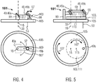
- Figs. 4 and 5 show different rotational support assemblies 101 with a range-setting support assembly 103.
- Fig. 4 shows a rotational support assembly 101 not forming part of the invention, whereas the rotational support assembly of Fig. 5 is embodied according to the present invention.
- Both assemblies 101, 103 may be attached to or supported by the optical carrier 47 of the inventive surgical microscope 1 or the further optical carrier 48 of the inventive retrofit-kit 41.
- the viewing direction of the lower panel of both figures is from the observation area 5 along the optical viewing axis 53 towards the at least one optical beam deflector 49.
- the upper panel of both figures shows a side view of the inventive rotational support assemblies 125.
- the first optical beam deflector 49a and the second optical beam deflector 49b are attached via posts 99 to a rotation base 105, which may perform a rotation 107 around the rotational axis 18 (of the rotational support assembly 101).
- the rotational axis 18 corresponds to the observation axis 33.
- a rotation 107 of the rotational support assembly 101 therefore does not change the relative position between the first optical beam deflector 49a and the second optical beam deflector 49b.
- This assembly which does not form part of the invention, furthermore comprises the range-setting support assembly 103 which comprises a guiding slot 109, along which the post 99 supporting the second optical beam deflector 49b may be moved following the linear trajectory 57.
- Figs. 4 and 5 do not show a drive system 97 for moving and/or tilting of the optical beam deflectors 49.
- Fig. 5 shows an embodiment of the inventive rotational support assembly 101, wherein the range-setting support assembly 103 is embodied as a radial range-setting support system 111.
- the first optical beam deflector 49a is supported by the rotation base 105 and rotatable around the rotational axis 18.
- the radial range-setting support system 111 of this embodiment does not perform a linear movement but a rotation 107 around a support system axis 113 which is essentially parallelly offset from the rotational axis 18.
- the second optical beam deflector 49b is supported by a post 99 and attached to a support system base 115 of the radial range-setting support system 111.
- the rotational support assembly 101 and the radial range-setting support system 111 are rotated in a synchronized manner.
- a combination of the rotation 107 of the rotational support assembly 101 and the (off-center) rotation 107 of the radial range-setting support system 111 may change the distance 59 between the first optical beam deflector 49a and the second optical beam deflector 49b.
- the optical beam deflectors 49 may also be rotatable in themselves, i.e. around a rotational axis through the corresponding beam deflector 49 and in particular relative to the rotational support assembly 101 and/or to the radial range-setting support system 111.
Description
- The invention relates to a surgical microscope for observing an object in an observation area during surgery. The invention further relates to a method for observing an object in an observation area during surgery and to a retrofit-kit.
- Surgical microscopes of the art are known but have several disadvantages. Changing a direction of observation is, for example, difficult as such a hange in the direction of observation, e.g. by rotating an optical carrier of the surgical microscope, also moves an optical eyepiece. Movement of the latter makes it difficult to keep the eyes (of the observer, e.g. a surgeon) aligned.
- Further solutions of the art apply a robotic arm which is controlled by a computer in order to set the position and rotation of the optics carrier. Such a robotic arm-based system, however, may require preoperative planning and the robotic arm is expensive, bulky, takes up valuable operation space in an operating room and its potential is not even close to being fully exploited.
-
DE 10 2006 010 767 shows a microscopy system comprising a tiltable mirror.EP 0 055 209 A2 is concerned with a ray deflection device for observing an object with optical instruments, such as a microscope, not only from the direction of the optical axis, but also from the direction that is inclined with respect to the optical axis. The motion and control of the optical elements is provided by mechanical means or using electronically programmable assemblies. The ray deflection device is rotatable about the optical axis either manually or using a motor. - In
US 2010/0 097 692 A1 , a microscope system is shown that comprises a rotational support assembly with an integrated linear range-setting support system that allows to radially shift an objective. The linear range-setting support system is rotatable by the rotational support assembly. - An object is therefore to provide a surgical microscope, a method and a retrofit-kit which allow an uninterrupted surgical workflow when the direction of observation is changed, and which is less costly and less bulky than a robotic arm.
- This object is solved by a surgical microscope for observing an object in an observation area during surgery, comprising an optical observation assembly and at least one optical carrier for variably deflecting an observation axis of the optical observation assembly into an optical viewing axis directed towards the observation area, wherein the observation area corresponds to the optical axis of the optical observation assembly, wherein the optical carrier comprises a pair of optical beam deflectors and is arranged between the optical observation assembly and the observation area, wherein the optical carrier comprises a rotational support assembly configured to support the pair of optical beam deflectors, the rotational support assembly being rotatable with respect to a rotational axis, wherein the rotational axis coincides with the observation axis of the optical observation assembly, wherein the optical carrier comprises a range-setting support system that supports at least one optical beam deflector of the pair of optical beam deflectors of the optical carrier and positions it at a variable distance from optical observation assembly, and wherein the range-setting support system is supported by the rotational support assembly, wherein the range-setting support system is a radial range-setting support system which is rotatable around a support system axis, wherein the rotation of the radial range-setting support system is synchronized with the rotation of the rotational support assembly, and wherein the support system axis is parallely offset from the rotational axis.
- Further, the above problem is solved by a method for observing an object in an observation area during surgery, comprising the steps of: variably deflecting an observation axis of an optical observation assembly into an optical viewing axis directed towards the observation area; and propagating light stemming from the observation area essentially along the optical viewing axis and the observation axis and imaging said light via an optical observation assembly; wherein the optical carrier comprises a pair of optical beam deflectors, a rotational support assembly configured to support the pair of optical beam deflectors, and a radial range-setting support system that supports at least one optical beam deflector of the pair of optical beam deflectors and is supported by the rotational support assembly, the method further comprising the steps of: rotating the rotational support assembly with respect to the observation axis; rotating the radial range-setting support system around the support system axis, the support system axis being parallel offset with respect to the observation axis, thereby positioning the at least one optical beam deflector at a variable distance from the optical observation assembly; and synchronizing the rotation of the rotational support assembly and the rotation of the radial range-setting support system.
- Finally, the above problem is also solved by a retrofit-kit for a surgical microscope, the retrofit-kit comprising at least one coupling with a pair of optical beam deflectors, an optical input axis, which is variably deflected into an optical output axis by the pair of optical beam deflectors, wherein the coupling is adapted to be mounted to a surgical microscope, such that the optical input axis corresponds to the observation axis of an optical observation assembly, wherein the optical viewing axis corresponds to an optical output axis of the retrofit-kit, wherein the optical carrier comprises a rotational support assembly configured to support the pair of optical beam deflectors, the rotational support assembly being rotatable with respect to a rotational axis, wherein the rotational axis coincides with the observation axis of the optical observation assembly, wherein the optical carrier comprises a range-setting support system that supports at least one optical beam deflector of the pair of optical beam deflectors of the optical carrier and positions it at a variable distance from the optical observation assembly, wherein the range-setting support system is supported by the rotational support assembly, wherein the range-setting support system is a radial range-setting support system which is rotatable around the support system axis, in that the rotation of the radial range-setting support system is synchronized with the rotation of the rotational support assembly, and wherein the support system axis is parallel offset from the rotational axis.
- The surgical microscope, the method and the retrofit-kit thus have the advantages that they are lighter, less expensive and less bulky than solutions of the art. The surgical microscope and/or the retrofit-kit may therefore be suitably applied in an existing operative or surgical environment. Furthermore, the surgical microscope, the retrofit-kit and the method allow for easy adjustment or change of the optical viewing axis without the need to position heavy and/or sensitive elements, such as the robotic arm. Consequently, the field of view is adjusted very rapidly. Preferably, the eyepiece as well as the surgeon's eyes may remain at a fixed position even during tilt and/or rotation of the optical viewing axis. The surgical microscope is thus more compact than the solutions disclosed in the art, e.g. surgical microscopes with a robotic arm.
- In that the rotational axis coincides with the observation axis of the optical observation assembly, the optical observation assembly may remain at a fixed position, wherein the pair of optical beam deflectors is rotated by means of the rotational support assembly.
- Further, a rotation of the rotational support assembly only modifies an angle between the optical observation assembly and the rotational support assembly and does not require realigning optical elements, e.g. the pair of optical beam deflectors of the rotational support assembly with respect to the observation axis. In other words, the observation axis may remain (preferably centered) on the pair of optical beam deflectors.
- A rotation of the at least one optical beam deflector allows the surgeon to change a viewing perspective. The change of perspective may mimic a movement of the surgical microscope to one side combined with a simultaneous tilt of its observation axis in order to remain pointed at the observation area. However, according to the invention, the optical observation assembly remains fixed and the perspective is changed merely by adjusting the at least one optical beam deflector.
- Using the radial range-setting support system has the advantage that the range of angular positioning of the optical viewing axis with respect to the observation area may be increased.
- The inventive surgical microscope, method and retrofit-kit may be improved by specific embodiments which will be described in the following. Technical features of the embodiments may be arbitrarily combined with each other or omitted if the technical effect obtained by the omitted technical feature(s) is not relevant to the present invention.
- The coupling is to be understood as a support structure which may be attached to a surgical microscope. Apart from the at least one optical beam deflector which may be attached to and supported by the optical carrier, any arbitrary number of optical elements like mirrors, lenses, prisms, refractive or catadioptric elements may be provided and supported by the optical carrier. The retrofit-kit may comprise a further optical carrier for supporting optical elements. The observation axis is determined by the optical observation assembly and in general corresponds to the optical axis of said assembly.
- The variable deflection of the observation axis into the optical viewing axis may be performed using at least one reflective element as a mirror, a refractive element like a prism (which may additionally provide a reflection, e.g. via total internal reflection) or a catadioptric element combining both. The above listed optical elements represent specific embodiments of the at least one optical beam deflector.
- The surgical microscope therefore may comprise an optical path, wherein light from the observation area propagating along the optical path from the observation area towards the optical carrier is deflected at or by the at least one optical beam deflector and consequently propagates through the optical observation assembly for imaging or observing.
- In the inventive surgical microscope the at least one optical beam deflector may be movable with respect to the optical observation assembly with regard to at least one of tilt and distance. The optical beam deflector moves with respect to the optical observation assembly, in particular tilts or translates such that a tilt and/or distance between the at least one optical beam deflector and the optical observation assembly is modified.
- This has the advantage that an observation angle, i.e. the angle at which the optical viewing axis is oriented with respect to the observation area, may be freely selected.
- Furthermore, the footprint, costs and complexity of the surgical microscope and the inventive method may be reduced. A viewing direction and viewing angle provided by the surgical microscope may be rapidly adjusted as the at least one movable optical beam deflector has a reduced inertia of the moving parts (as compared to a robotic arm). Such a deflection mechanism may furthermore be much more compact than a robotic arm.
- In the inventive surgical microscope the optical carrier comprises a pair of optical beam deflectors, of which at least one is tiltable and moveable with respect to the other. In the corresponding inventive method, at least one optical beam deflector of the pair of optical beam deflectors deflects the observation axis.
- This has the advantage that the possible variation of the observation angle, as well as the position of the optical viewing axis may be further increased. Additionally, a more complex optical path may be possible, e.g. if an incident angle on at least one optical beam deflector is limited (also limiting an angle of deflection) but a larger angle of deflection is desired.
- Either one or both optical beam deflectors of the pair may be tiltable and/or movable, wherein preferably both optical beam deflectors are at least tiltable. Also, both beam deflectors may be movable with respect to each other. A movement is to be understood to comprise a tilt, rotation and linear translation, i.e. a general change of spatial position and/or orientation.
- The movement of the at least one optical beam deflector of the pair is preferably performed along the optical path, such that changing the distance between the at least one optical beam deflector and the optical observation assembly or the distance between both optical beam deflectors (of the pair) does not require readjusting the tilt of the at least one optical beam deflector. Furthermore, the optical path preferably corresponds to the observation axis and the optical viewing axis, which may be approximately centered on optical components as, for instance, the at least one optical beam deflector.
- In another embodiment of the invention, more than two optical beam deflectors may be provided. Such an embodiment allows for more complex optical paths as well as for dividing a desired deflection of the optical path on two optical beam deflectors. The latter may have a limited angular range within which a deflection is possible (cp. the maximum glancing angle if total internal reflection is applied).
- In another embodiment of the inventive surgical microscope a drive system for moving and/or tilting of the at least one optical beam deflector may be provided. The corresponding inventive method therefore moves and/or tilts the at least one optical beam deflector using a drive system.
- Such a drive system has the advantage that the variable deflection of the observation axis may be automated, to allow an observer, e.g. the surgeon, to easily adjust the optical viewing axis of the surgical microscope by means of control interface means as, for instance, buttons, a joystick or the like.
- The drive system may comprise linear translation stages and/or rotational or tilt stages which allow for precise and repeatable adjustment of the optical viewing axis.
- In another embodiment of the inventive surgical microscope, a controller module may be provided, wherein said controller module may have at least one control data input terminal for inputting control data and at least one driving data output terminal connected to the drive system for providing driving data to the drive system. The controller module therefore transcribes or translates control data which are input into output driving data and provides such data to the drive system. The controller module controls the drive system. This may be performed using open loop or closed loop controlling performed by a corresponding open loop circuit or closed loop circuit comprised in the controller module. The control data may be manually input, e.g. by pressing a button or by a variation of a suitable physical property which is manually changed by the observer, e.g. the surgeon. One simple example of manually input control data is the variable resistance of a potentiometer set by the surgeon. The resistance may correspond to a tilt of the at least one optical beam deflector.
- The control data may also be provided by a computer, i.e. in the form of a digital signal.
- The pair of optical beam deflectors is rotated around the rotational axis and does not change its relative position with respect to the rotational support assembly during a rotation.
- It is particularly advantageous if a variable deflection of the observation axis into the optical viewing axis does not change further optical properties of the surgical microscope. Exemplarily, adjusting the deflection may maintain the length of the optical path and consequently also the setting of the focal position of the surgical microscope.
- However, in further embodiments of the inventive surgical microscope, a focus readjustment module may be provided which detects a change in the optical path length and adapts the focusing of optical elements of the surgical microscope. Here, as an example, an electrically tunable lens may be applied to readjust the focus (i.e. to change the set focal distance) of the surgical microscope.
- It may be possible to define an origin of the optical viewing axis at an optical beam deflector, in particular at the beam deflector which is closest to the observation area. The movable range-setting support system changes the position of said origin. The term "origin" is to be understood as one predetermined point through which the optical viewing axis as well as the optical path passes. It is not to be understood as the point from which electromagnetic radiation is emitted. The movable range-setting support system therefore allows the possible tilt of the optical viewing axis to be altered and, additionally, to translate the resulting optical viewing axis parallelly by means of the movement via the movable range-setting support system.
- By means of a range-setting support system, the distance between the two optical beam deflectors may be varied (if the pair of optical beam deflectors is applied). Preferably, the movement of the range-setting support system occurs along the optical path.
- The range-setting support system is supported by the rotational support system. This has the advantage that a rotation of the rotational support system does not misalign the at least one optical beam deflector which is moved by the range-setting support system as the entire range-setting support system may be rotated.
- A movable range setting support system not forming part of the present invention may provide a guiding element such as a guiding trail, an elongated guiding recess, a guiding rod or a similar structure. Along said structure, the at least one optical beam deflector may be linearly translated.
- Another embodiment of the inventive surgical microscope may comprise a light source arrangement for providing illumination light and/or excitation light to the observation area. The illumination light may be partially reflected or partially transmitted by the object located in the observation area.
- Similarly, excitation light may be provided to the observation area, wherein said excitation light may trigger the generation of electromagnetic radiation (e.g. by excitation of fluorescence). Said electromagnetic radiation or illumination light being spatially modified by reflection or transmission at or through the object may be referred to as observation light. The observation light represents spatially resolved physical properties of the object and may propagate along the optical viewing axis, through the optical carrier (and eventually through the further optical carrier if a retrofit-kit is applied) and is in particular deflected by the at least one optical beam deflector and subsequently propagates to or into the optical observation assembly for observation.
- The light source arrangement may comprise one or more light sources, one or more optical components like optical fibers, lenses, mirrors and the like. Specific light sources may be applied, which may be continuous light sources or pulsed light sources. Moreover, the light sources may emit light in a wavelength range which is not visible to the human eye.
- Furthermore, coupling means may be provided for coupling light of the at least one light source into the surgical microscope. This may, for example, be realized by an optical beam combiner or a dichroic mirror.
- Coupling light of the at least one light source into the surgical microscope is to be understood as the process of obtaining a propagation of the illumination light and/or the excitation light at least in portions essentially coaxial to the optical viewing axis.
- In a further embodiment of the inventive surgical microscope, the range-setting support system comprises a through-hole for providing access to the at least one optical beam deflector from the observation area. Said through-hole may be round or slotted and may additionally be embodied as a guiding recess or a guiding slotted hole applied as a pass-through opening for the optical path. Such a through-hole allows for a compact setup of the surgical microscope and for further miniaturization.
- In the inventive surgical microscope or inventive method, the range-setting support system is a radial range-setting support system which is rotatable around a support system axis, wherein the rotation of the radial range-setting support system is synchronized with the rotation of the rotational support assembly.
- Thus, two rotational movements may be combined in order to change the distance between the at least one optical beam deflector and the optical observation assembly. The synchronization may require an additional rotation of the element, i.e. the optical beam deflector attached at or supported by the radial range-setting support system. The at least one (linearly movable) optical beam deflector is positioned off-center with respect to the support system axis.
- In particular, if a pair of optical beam deflectors is applied, a first optical beam deflector may be attached to the radial range-setting support system, wherein a second optical beam deflector is not attached to the radial range setting support system. In this setup, the second optical beam deflector is rotated together with the rotational support assembly, whereas the first optical beam deflector is rotated by the rotational support assembly as well but additionally rotated by means of the radial range-setting support system. Thus, it may be required that the first and/or the second optical beam deflector are supported in a rotatable manner. In other words, the first and/or the second optical beam deflector may be rotatable independently on a rotation of the rotational support assembly or the radial range-setting support system. This allows preventing misalignment of the optical path with respect to the optical beam deflectors.
- The above described embodiments of the inventive surgical microscope and the corresponding embodiment of the inventive method may be performed using a corresponding embodiment of the retrofit-kit. Such a retrofit-kit thus supplements prior art surgical microscopes such that a surgical microscope according to the invention is obtained.
- The inventive surgical microscope may comprise any number of optical beam deflectors and rotational degrees of freedom. Similarly, a tilt of any optical or mechanical component may be possible around one or two axes, linear movement may be possible along all three spatial directions, being preferably orthogonal to each other. The optical observation assembly may comprise any number of optical observation means including a plurality of eyepieces.
- Embodiments comprising a light source arrangement may comprise any number of light sources and may combine the corresponding output radiation in any arbitrary composition.
- In the following, the present invention is described using accompanying figures which show specific embodiments of the inventive surgical microscope and retrofit-kit. The corresponding embodiments of the inventive method are covered by the description of the respective surgical microscope. Purely exemplary embodiments are shown in the figures, wherein specific technical features of the embodiments may be arbitrarily combined with each other or even omitted if the technical effect obtained by the omitted technical features is not relevant to the present invention. Identical technical features and technical features having the same technical effect will be denoted using the same reference numeral. A repetitive description will be omitted, while differences in technical features between two figures will be emphasized.
- The figures show:
- Fig. 1
- a surgical microscope of the art;
- Fig. 2
- a surgical microscope of the art with a retrofit-kit according to the invention;
- Fig. 3
- a first embodiment of the inventive surgical microscope;
- Fig. 4
- a rotational support assembly with a range-setting support assembly not forming part of the present invention; and
- Fig. 5
- the inventive rotational support assembly with a range-setting support assembly.
- In
Fig. 1 asurgical microscope 1 of the art is shown in a perspective view. Thesurgical microscope 1 is applied for observing anobject 3 in anobservation area 5 during a surgery and is shown in a perspective view. -
Surgical microscopes 1 of the art comprise an optical observation assembly 7 which comprises an eyepiece 9, also referred to as ocular 11, and anobjective assembly 13 which is merely indicated by a dashed line. - The
surgical microscope 1 may be mounted on agimbal mount 15 which comprises threejoints 17 in the embodiment shown. Thesurgical microscope 1 is rotatable about threerotational axes 18. Afirst rotation 21 is around a vertical axis 19, asecond rotation 23 around a firsthorizontal axis 25 and athird rotation 27 around a secondhorizontal axis 29. Therotational axes - The first 21, the second 23 and the
third rotation 27 result in atilt 31 of anobservation axis 33 of the optical observation assembly 7. In the figure, threepositions 32 of theobservation axis 33 are indicated. Theserotations tilt 31 of the optical observation assembly 7 and consequently also of the eyepiece 9. A surgeon 35 therefore has to follow thetilt 31 of the optical observation assembly 7 and to change his or her observation position 37. This may interrupt the flow of the surgery. - The
observation axis 33 is centered in theobservation area 5, wherein the latter is defined by a field ofview 39 being a characteristic of the optical observation assembly 7 (which may e.g. be determined by the numerical aperture of optical components (not shown) of the optical observation assembly 7). - It is to be noted that different embodiments of the prior art may comprise only one or two
rotational axes 18 and may comprise a mounting system different than thegimbal mount 15 shown inFig. 1 . -
Fig. 2 is a side view of asurgical microscope 1 of the art and a retrofit-kit 41 according to the invention, wherein the retrofit-kit 41 is partially cut, i.e. an interior 43 comprised within ahousing 45 is shown. The retrofit-kit 41 is mounted to thesurgical microscope 1 by acoupling 46 which is ring-shaped and which may support the at least one beam deflector in another embodiment. - The
surgical microscope 1 comprises anoptical carrier 47 shown in a partially cut portion. Saidoptical carrier 47 supports optical elements (not shown) of thesurgical microscope 1. - In the interior 43 of the retrofit-kit, a further
optical carrier 48 is schematically indicated with a dashed line, wherein reference is made toFigs. 4 and 5 in which two specific embodiments of the optical carrier 47 (in case of an inventive surgical microscope; or the furtheroptical carrier 48, if a retrofit-kit 41 is used) are shown. - The further
optical carrier 48 comprises two optical beam deflectors 49, i.e. apair 50 of beam deflectors 49, which are mirrors 51 in the embodiment shown inFig. 2 . In different embodiments of the inventive retrofit-kit 41 the optical beam deflectors 49 may be embodied as refractive elements like prisms or catadioptric elements (not shown). A similar set-up may be provided in an inventive surgical microscope 1 (this specific embodiment is not shown), wherein in such a case at least one of the above-mentioned elements is provided on or at theoptical carrier 47. - Instead of tilting the entire
surgical microscope 1, a firstoptical beam deflector 49a may perform thefirst rotation 21 and thesecond rotation 23. Thethird rotation 27 is not envisaged in the embodiment shown but may be provided in another embodiment of the inventive retrofit-kit 41. Thesurgical microscope 1 therefore remains at a fixed position and there is no need for the surgeon 35 to readjust his or her observation position 37. - Additionally or alternatively, also a second
optical beam deflector 49b may be tiltable. Theobservation axis 33 corresponds to an optical input axis 33a of the retrofit-kit 41. Thisobservation axis 33 is deflected by the optical beam deflectors 49 (or by a single optical beam deflector 49 in another embodiment of the invention) into anoptical viewing axis 53 which is directed towards theobservation area 5 of theobject 3 and which may consequently comprise avariable tilt 31 introduced by the optical beam deflectors 49. Also inFig. 2 , threepositions 32 of theoptical viewing axis 53 are shown. Theoptical viewing axis 53 corresponds to an optical output axis 54 of the retrofit-kit 41. - The
housing 45 of the retrofit-kit 41 comprises a through-hole 55 which provides access to the at least one optical beam deflector 49 from theobservation area 5. - The inventive retrofit-
kit 41 ofFig. 2 may be improved by providing a beam combiner and a light source. Those elements are shown inFig. 3 for the inventivesurgical microscope 1. -
Fig. 3 shows a first embodiment of the inventivesurgical microscope 1, wherein the schematic drawing is shown partially cut for revealing the interior 43 of the inventivesurgical microscope 1. Theoptical carrier 47, to which thepair 50 of the two optical beam deflectors 49 is attached, is merely indicated. - In comparison to the inventive retrofit-
kit 41 shown inFig. 2 , the inventivesurgical microscope 1 ofFig. 3 has a fixed firstoptical beam deflector 49a, wherein the secondoptical beam deflector 49b is tiltable. Said secondoptical beam deflector 49b is furthermore movable along atrajectory 57 which indicates a linear movement of the secondoptical beam deflector 49b with respect to the firstoptical beam deflector 49a. In other embodiments of the invention, also the firstoptical beam deflector 49a or both beam deflectors 49 may be movable. - The embodiment shown in
Fig. 3 therefore allows changing thetilt 31 of theoptical viewing axis 53 as well as adistance 59 between the firstoptical beam deflector 49a and the secondoptical beam deflector 49b. - By changing said
distance 59, an origin 61 of theoptical viewing axis 53 may be relocated for changing the viewing perspective. This is exemplarily indicated by anexample origin 61a indicated by a cross, from whichexample origin 61a and exampleoptical viewing axis 53a may be set by a surgeon 35 (not shown). Thus,Fig. 3 shows fourpositions 32 of theoptical viewing axis 53. Such an oblique exampleoptical viewing axis 53a may, in combination with a repositioning of theobject 3, allow for observation of aportion 63 in an undercutarea 65. Saidportion 63 is exemplarily shown in the figure. - A limitation of the movement of the second
optical beam deflector 49b is determined by thetilt 31 of saiddeflector 49b, by the maximum change of thedistance 59 and by the size of the through-hole 55. - The origin 61 is to be understood as the point at which a deflected
observation axis 67 is incident on the secondoptical beam deflector 49b (or on the at least one optical beam deflector 49 if only one such element is applied). - As shown in a
rectangle 69 inFig. 3 , thesurgical microscope 1 may comprise a light source arrangement 71 which may comprise at least one light source 73. In the rectangle 69 a first light source 73a and a second light source 73b are indicated, wherein any arbitrary number of light sources 73 may be provided. The light sources 73a, 73b may operate in different wavelength ranges and may be pulsed light sources (not shown) or continuous light sources (not shown). - In the embodiment shown in
Fig. 3 , the first light source 73a emitsillumination light 75 which is indicated by a dashed line. The second light source 73b emitsexcitation light 77 indicated by a dotted line. - The first
optical beam deflector 49a is a beam combiner 79, in particular a first beam combiner 79a, which is reflective for observation light 81 propagating from the observation area towards the eyepiece 9. The first beam combiner 79a is in particular reflective for the observation light 81 at a specific, predetermined angle, here approximately 45°. The first beam combiner 79a is furthermore highly transparent for theillumination light 75 and theexcitation light 77. - The embodiment of the inventive
surgical microscope 1 shown inFig. 3 furthermore comprises a second beam combiner 79b which is highly transparent for at least theexcitation light 77 and reflective for theillumination light 75, in particular at an angle of incidence of approximately 45°. - The arrangement of the first 79a and the second beam combiner 79b allow concurrent overlapping of the
illumination light 75 and/or theexcitation light 77 with the deflected observation axis 67 (solid line). Only for the sake of visibility, theillumination light 75, theexcitation light 77 and the deflectedobservation axis 67 are drawn spaced apart from each other. - The embodiment of the inventive
surgical microscope 1 shown inFig. 3 furthermore comprises acontroller module 83 with at least one controldata input terminal 85 for inputting control data 87 which is indicated by a single rectangular pulse 89. - The
controller module 83 also comprises at least one drivingdata output terminal 91 for providing driving data 93 which is indicated by a pulse sequence 95. Said driving data 93 is provided to a drive system 97 which is provided at apost 99 which supports the secondoptical beam deflector 49b. The drive system 97 allows moving and/or tilting of the at least one optical beam deflector 49, in the embodiment shown the secondoptical beam deflector 49b is moved and/or tilted. The drive system 97 may thus comprise linear actuators (not shown) and rotational actuators (not shown). -
Figs. 4 and 5 show differentrotational support assemblies 101 with a range-settingsupport assembly 103.Fig. 4 shows arotational support assembly 101 not forming part of the invention, whereas the rotational support assembly ofFig. 5 is embodied according to the present invention. Bothassemblies optical carrier 47 of the inventivesurgical microscope 1 or the furtheroptical carrier 48 of the inventive retrofit-kit 41. The viewing direction of the lower panel of both figures is from theobservation area 5 along theoptical viewing axis 53 towards the at least one optical beam deflector 49. The upper panel of both figures shows a side view of the inventive rotational support assemblies 125. - In the
rotational support assembly 101 shown inFig. 4 , the firstoptical beam deflector 49a and the secondoptical beam deflector 49b are attached viaposts 99 to arotation base 105, which may perform arotation 107 around the rotational axis 18 (of the rotational support assembly 101). Therotational axis 18 corresponds to theobservation axis 33. Arotation 107 of therotational support assembly 101 therefore does not change the relative position between the firstoptical beam deflector 49a and the secondoptical beam deflector 49b. - This assembly, which does not form part of the invention, furthermore comprises the range-setting
support assembly 103 which comprises a guidingslot 109, along which thepost 99 supporting the secondoptical beam deflector 49b may be moved following thelinear trajectory 57.Figs. 4 and 5 do not show a drive system 97 for moving and/or tilting of the optical beam deflectors 49. -
Fig. 5 shows an embodiment of the inventiverotational support assembly 101, wherein the range-settingsupport assembly 103 is embodied as a radial range-settingsupport system 111. In this embodiment, the firstoptical beam deflector 49a is supported by therotation base 105 and rotatable around therotational axis 18. The radial range-settingsupport system 111 of this embodiment does not perform a linear movement but arotation 107 around asupport system axis 113 which is essentially parallelly offset from therotational axis 18. - The second
optical beam deflector 49b is supported by apost 99 and attached to asupport system base 115 of the radial range-settingsupport system 111. - The
rotational support assembly 101 and the radial range-settingsupport system 111 are rotated in a synchronized manner. - In particular, a combination of the
rotation 107 of therotational support assembly 101 and the (off-center)rotation 107 of the radial range-settingsupport system 111 may change thedistance 59 between the firstoptical beam deflector 49a and the secondoptical beam deflector 49b. - In order to maintain an
optical path 117 on the firstoptical beam deflector 49a on the secondoptical beam deflector 49b, the optical beam deflectors 49 may also be rotatable in themselves, i.e. around a rotational axis through the corresponding beam deflector 49 and in particular relative to therotational support assembly 101 and/or to the radial range-settingsupport system 111. -
- 1
- surgical microscope
- 3
- object
- 5
- observation area
- 7
- optical observation assembly
- 9
- eyepiece
- 11
- ocular
- 13
- objective assembly
- 15
- gimbal mount
- 17
- joint
- 18
- rotational axis
- 19
- vertical axis
- 21
- first rotation
- 23
- second rotation
- 25
- first horizontal axis
- 27
- third rotation
- 29
- second horizontal axis
- 31
- tilt
- 32
- position
- 33
- observation axis
- 33a
- optical input axis
- 35
- surgeon
- 37
- observation position
- 39
- field of view
- 41
- retrofit-kit
- 43
- interior
- 45
- housing
- 46
- coupling
- 47
- optical carrier
- 48
- further optical carrier
- 49
- optical beam deflector
- 49a
- first optical beam deflector
- 49b
- second optical beam deflector
- 50
- pair
- 51
- mirror
- 53
- optical viewing axis
- 53a
- example optical viewing axis
- 54
- optical output axis
- 55
- through-hole
- 57
- trajectory
- 59
- distance
- 61
- origin
- 61a
- example origin
- 63
- portion
- 65
- undercut area
- 67
- deflected observation axis
- 69
- angle
- 71
- light source arrangement
- 73
- light source
- 75
- illumination light
- 77
- excitation light
- 79
- beam combiner
- 79a
- first beam combiner
- 79b
- second beam combiner
- 81
- observation light
- 83
- controller module
- 85
- control data input terminal
- 87
- control data
- 89
- rectangular pulse
- 91
- driving data output terminal
- 93
- driving data
- 95
- pulse sequence
- 97
- drive system
- 99
- port
- 101
- rotational support assembly
- 103
- range-setting support assembly
- 105
- rotational base
- 107
- rotation
- 109
- guiding slot
- 111
- radial range-setting support system
- 113
- support system axis
- 115
- support system base
- 117
- optical path
Claims (9)
- Surgical microscope (1) for observing an object (3) in an observation area (5) during surgery, comprising an optical observation assembly (7) and at least one optical carrier (47) for variably deflecting an observation axis (33) of the optical observation assembly (7) into an optical viewing axis (53) directed towards the observation area (5), wherein the observation axis (33) corresponds to the optical axis of the optical observation assembly (7), wherein the optical carrier (47) comprises a pair (50) of optical beam deflectors (49) and is arranged between the optical observation assembly (7) and the observation area (5), wherein the optical carrier (47) comprises a rotational support assembly (101) configured to support the pair (50) of optical beam deflectors (49), the rotational support assembly (101) being rotatable with respect to a rotational axis (18), wherein the rotational axis (18) coincides with the observation axis (33) of the optical observation assembly (7), wherein the optical carrier (47) comprises a range-setting support system (103) that supports at least one optical beam deflector (49) of the pair (50) of optical beam deflectors (49) of the optical carrier (47) and positions it at a variable distance (59) from the optical observation assembly (7), and wherein the range-setting support system (103) is supported by the rotational support assembly (101), characterized in that the range-setting support system (103) is a radial range-setting support system (111) which is rotatable around a support system axis (113), wherein the rotation (107) of the radial range-setting support system (103) is synchronized with the rotation (107) of the rotational support assembly (101), and wherein the support system axis (113) is parallelly offset from the rotational axis (18).
- Surgical microscope (1) according to claim 1, characterized in that the at least one optical beam deflector (49) of the pair (50) of optical beam deflectors (49) is moveable with respect to the optical observation assembly (7) with regard to at least one of tilt (31) and distance (59).
- Surgical microscope (1) according to claim 1 or 2, characterized by a drive system (97) for moving and/or tilting of the at least one optical beam deflector (49).
- Surgical microscope (1) according to claim 3, characterized by a controller module (83) with at least one control data input terminal (85) for inputting control data (87) and with at least one driving data output terminal (91) connected to the drive system (97) for providing driving data (93) to the drive system (97).
- Surgical microscope (1) according to any one of claims 1 to 4, characterized by a light source arrangement (71) for providing illumination light (75) and/or excitation light (77) to the observation area (5).
- Surgical microscope (1) according to claim 5, characterized in that the illumination light (75) and/or the excitation light (77) propagates at least in portions essentially coaxial to the optical viewing axis (53).
- Surgical microscope (1) according to any one of claims 1 to 6, characterized in that the range-setting support system (103) comprises a through-hole (55) for providing access to the at least one optical beam deflector (49) of the pair (50) of optical beam deflectors (49) from the observation area (5).
- Method for observing an object (3) in an observation area (5) during surgery, comprising the steps of:- variably deflecting an observation axis (33) of an optical observation assembly (7) into an optical viewing axis (53) directed towards the observation area (5); and- propagating light (81) stemming from the observation area (5) essentially along the optical viewing axis (53) and the observation axis (33) and imaging said light (81) via an optical observation assembly (7),wherein the optical carrier (47) comprises a pair (50) of optical beam deflectors (49), a rotational support assembly (101) configured to support the pair (50) of optical beam deflectors (49), and a radial range-setting support system (111) that supports at least one optical beam deflector (49) of the pair (50) of optical beam deflectors (49) and is supported by the rotational support-assembly (101),
the method further comprising the steps of:- rotating the rotational support assembly (101) with respect to the observation axis (33);- rotating the radial range-setting support system (111) around a support system axis (113), the support system axis (113) being parallelly offset with respect to the observation axis (33), thereby positioning the at least one optical beam deflector (44) at a variable distance (59) from the optical observation assembly (7); and- synchronising the rotation of the rotational support assembly (101) and the rotation of the radial range-setting support system (111). - Retrofit-kit (41) for a surgical microscope (1), comprising at least one coupling (46) with a pair (50) of optical beam deflectors (49), an optical input axis (33a) which is variably deflected into an optical output axis (54) by the pair (50) of optical beam deflectors (49), wherein the coupling (46) is adapted to be mounted to a surgical microscope (1), such that the optical input axis (33a) corresponds to the observation axis (33) of an optical observation assembly (7) of the surgical microscope (1), wherein the optical viewing axis (53) corresponds to an optical output axis (54) of the retrofit-kit (53), , wherein the optical carrier (47) comprises a rotational support assembly (101) configured to support the pair (50) of optical beam deflectors (49), the rotational support assembly (10) being rotatable with respect to a rotational axis (18), wherein the rotational axis (18) coincides with the observation axis (33) of the optical observation assembly (7), wherein the optical carrier (47) comprises a range-setting support system (103) that supports at least one optical beam deflector (49) of the pair (50) of optical beam deflectors (49) of the optical carrier (47) and positions it at a variable distance (59) from the optical observation assembly (7), wherein the range-setting support system (103) is supported by the rotational support assembly (101), characterized in that the range-setting support system (103) is a radial range-setting support system (111) which is rotatable around a support system axis (113), in that the rotation (107) of the radial range-setting support system (111) is synchronized with the rotation (107) of the rotational support assembly (101), and wherein the support system axis (113) is parallelly offset from the rotational axis (18).
Priority Applications (4)
| Application Number | Priority Date | Filing Date | Title |
|---|---|---|---|
| EP18158423.6A EP3531184B1 (en) | 2018-02-23 | 2018-02-23 | Surgical microscope with movable beam deflector, method for operating the same and retrofit-kit |
| US16/274,315 US11333873B2 (en) | 2018-02-23 | 2019-02-13 | Surgical microscope with movable beam deflector, method for operating the same and retrofit-kit |
| CN201910126256.XA CN110187485B (en) | 2018-02-23 | 2019-02-20 | Surgical microscope with movable beam deflector, method of operating same and retrofit kit |
| JP2019030493A JP2019144555A (en) | 2018-02-23 | 2019-02-22 | Surgical microscope including movable beam deflector, and actuation method of surgical microscope, as well as retrofit kit |
Applications Claiming Priority (1)
| Application Number | Priority Date | Filing Date | Title |
|---|---|---|---|
| EP18158423.6A EP3531184B1 (en) | 2018-02-23 | 2018-02-23 | Surgical microscope with movable beam deflector, method for operating the same and retrofit-kit |
Publications (2)
| Publication Number | Publication Date |
|---|---|
| EP3531184A1 EP3531184A1 (en) | 2019-08-28 |
| EP3531184B1 true EP3531184B1 (en) | 2022-06-29 |
Family
ID=61283007
Family Applications (1)
| Application Number | Title | Priority Date | Filing Date |
|---|---|---|---|
| EP18158423.6A Active EP3531184B1 (en) | 2018-02-23 | 2018-02-23 | Surgical microscope with movable beam deflector, method for operating the same and retrofit-kit |
Country Status (4)
| Country | Link |
|---|---|
| US (1) | US11333873B2 (en) |
| EP (1) | EP3531184B1 (en) |
| JP (1) | JP2019144555A (en) |
| CN (1) | CN110187485B (en) |
Families Citing this family (1)
| Publication number | Priority date | Publication date | Assignee | Title |
|---|---|---|---|---|
| FR3105448B1 (en) * | 2019-12-20 | 2021-12-10 | Centre Nat Etd Spatiales | Improved eccentric scanning device |
Citations (1)
| Publication number | Priority date | Publication date | Assignee | Title |
|---|---|---|---|---|
| EP0055209A2 (en) * | 1980-12-18 | 1982-06-30 | Wild Heerbrugg Ag. | Beam folding device |
Family Cites Families (7)
| Publication number | Priority date | Publication date | Assignee | Title |
|---|---|---|---|---|
| DE102006012388A1 (en) | 2005-10-20 | 2007-04-26 | Carl Zeiss Surgical Gmbh | microscopy system |
| DE102006009452B4 (en) | 2005-10-20 | 2010-07-01 | Carl Zeiss Surgical Gmbh | stereomicroscope |
| DE102006010767B4 (en) * | 2006-03-08 | 2008-04-17 | Carl Zeiss Surgical Gmbh | microscopy system |
| CN201048981Y (en) * | 2007-03-09 | 2008-04-23 | 长春中吉光电设备有限公司 | Ultra-pulse CO2 laser microsurgery operating system |
| US8077386B2 (en) * | 2008-10-22 | 2011-12-13 | Microbrightfield, Inc. | Movable objective lens assembly for an optical microscope and optical microscopes having such an assembly |
| DE102011114523A1 (en) * | 2011-09-29 | 2013-04-04 | Carl Zeiss Meditec Ag | Module for transmitting a light beam |
| DE102017110779A1 (en) * | 2017-05-17 | 2018-11-22 | Carl Zeiss Meditec Ag | Surgical microscope with at least one optical path switching device |
-
2018
- 2018-02-23 EP EP18158423.6A patent/EP3531184B1/en active Active
-
2019
- 2019-02-13 US US16/274,315 patent/US11333873B2/en active Active
- 2019-02-20 CN CN201910126256.XA patent/CN110187485B/en active Active
- 2019-02-22 JP JP2019030493A patent/JP2019144555A/en active Pending
Patent Citations (1)
| Publication number | Priority date | Publication date | Assignee | Title |
|---|---|---|---|---|
| EP0055209A2 (en) * | 1980-12-18 | 1982-06-30 | Wild Heerbrugg Ag. | Beam folding device |
Also Published As
| Publication number | Publication date |
|---|---|
| CN110187485A (en) | 2019-08-30 |
| CN110187485B (en) | 2022-05-24 |
| EP3531184A1 (en) | 2019-08-28 |
| US11333873B2 (en) | 2022-05-17 |
| US20190265453A1 (en) | 2019-08-29 |
| JP2019144555A (en) | 2019-08-29 |
Similar Documents
| Publication | Publication Date | Title |
|---|---|---|
| US7957057B2 (en) | Microscope optical system, microscope, and virtual slide forming system | |
| KR101056484B1 (en) | Optical system for forming optical path of oblique angle and method thereof | |
| JP5327670B2 (en) | Surgical stereo microscope | |
| JP5578550B2 (en) | Ophthalmic laser treatment device | |
| JP5043604B2 (en) | Stereo microscope | |
| US7586676B2 (en) | Optical device with increased depth of field | |
| US20030048530A1 (en) | Microscope having a system for reflecting in illumination | |
| US7760426B2 (en) | Optical axis reorientation device for surgical microscope | |
| US6972900B2 (en) | Microscope, particularly a stereomicroscope | |
| EP3531184B1 (en) | Surgical microscope with movable beam deflector, method for operating the same and retrofit-kit | |
| JP5562713B2 (en) | Ophthalmic laser treatment device | |
| US8027085B2 (en) | Microscope with centered illumination | |
| US20070121201A1 (en) | Stereomicroscope | |
| JP2004109488A (en) | Stereoscopic microscope | |
| US10842590B2 (en) | Medical observation apparatus with a movable beam deflector and method for operating the same | |
| JP2002214535A (en) | Microscopic apparatus | |
| JP4615840B2 (en) | Surgical observation device | |
| JP2003177326A (en) | Operating microscope | |
| JP4499223B2 (en) | Surgical microscope | |
| JP2003270544A (en) | Stereomicroscope | |
| JP2002328308A (en) | Microscope | |
| JPH0727981A (en) | Stereomicroscope | |
| JPH02234112A (en) | Optical apparatus |
Legal Events
| Date | Code | Title | Description |
|---|---|---|---|
| PUAI | Public reference made under article 153(3) epc to a published international application that has entered the european phase |
Free format text: ORIGINAL CODE: 0009012 |
|
| STAA | Information on the status of an ep patent application or granted ep patent |
Free format text: STATUS: THE APPLICATION HAS BEEN PUBLISHED |
|
| AK | Designated contracting states |
Kind code of ref document: A1 Designated state(s): AL AT BE BG CH CY CZ DE DK EE ES FI FR GB GR HR HU IE IS IT LI LT LU LV MC MK MT NL NO PL PT RO RS SE SI SK SM TR |
|
| AX | Request for extension of the european patent |
Extension state: BA ME |
|
| STAA | Information on the status of an ep patent application or granted ep patent |
Free format text: STATUS: REQUEST FOR EXAMINATION WAS MADE |
|
| 17P | Request for examination filed |
Effective date: 20200227 |
|
| RBV | Designated contracting states (corrected) |
Designated state(s): AL AT BE BG CH CY CZ DE DK EE ES FI FR GB GR HR HU IE IS IT LI LT LU LV MC MK MT NL NO PL PT RO RS SE SI SK SM TR |
|
| STAA | Information on the status of an ep patent application or granted ep patent |
Free format text: STATUS: EXAMINATION IS IN PROGRESS |
|
| 17Q | First examination report despatched |
Effective date: 20200618 |
|
| STAA | Information on the status of an ep patent application or granted ep patent |
Free format text: STATUS: EXAMINATION IS IN PROGRESS |
|
| STAA | Information on the status of an ep patent application or granted ep patent |
Free format text: STATUS: EXAMINATION IS IN PROGRESS |
|
| GRAP | Despatch of communication of intention to grant a patent |
Free format text: ORIGINAL CODE: EPIDOSNIGR1 |
|
| STAA | Information on the status of an ep patent application or granted ep patent |
Free format text: STATUS: GRANT OF PATENT IS INTENDED |
|
| INTG | Intention to grant announced |
Effective date: 20210722 |
|
| GRAJ | Information related to disapproval of communication of intention to grant by the applicant or resumption of examination proceedings by the epo deleted |
Free format text: ORIGINAL CODE: EPIDOSDIGR1 |
|
| STAA | Information on the status of an ep patent application or granted ep patent |
Free format text: STATUS: EXAMINATION IS IN PROGRESS |
|
| INTC | Intention to grant announced (deleted) | ||
| GRAP | Despatch of communication of intention to grant a patent |
Free format text: ORIGINAL CODE: EPIDOSNIGR1 |
|
| STAA | Information on the status of an ep patent application or granted ep patent |
Free format text: STATUS: GRANT OF PATENT IS INTENDED |
|
| INTG | Intention to grant announced |
Effective date: 20220112 |
|
| GRAS | Grant fee paid |
Free format text: ORIGINAL CODE: EPIDOSNIGR3 |
|
| GRAA | (expected) grant |
Free format text: ORIGINAL CODE: 0009210 |
|
| STAA | Information on the status of an ep patent application or granted ep patent |
Free format text: STATUS: THE PATENT HAS BEEN GRANTED |
|
| AK | Designated contracting states |
Kind code of ref document: B1 Designated state(s): AL AT BE BG CH CY CZ DE DK EE ES FI FR GB GR HR HU IE IS IT LI LT LU LV MC MK MT NL NO PL PT RO RS SE SI SK SM TR |
|
| REG | Reference to a national code |
Ref country code: CH Ref legal event code: EP |
|
| REG | Reference to a national code |
Ref country code: AT Ref legal event code: REF Ref document number: 1501719 Country of ref document: AT Kind code of ref document: T Effective date: 20220715 |
|
| REG | Reference to a national code |
Ref country code: IE Ref legal event code: FG4D |
|
| REG | Reference to a national code |
Ref country code: DE Ref legal event code: R096 Ref document number: 602018037204 Country of ref document: DE |
|
| REG | Reference to a national code |
Ref country code: LT Ref legal event code: MG9D |
|
| PG25 | Lapsed in a contracting state [announced via postgrant information from national office to epo] |
Ref country code: SE Free format text: LAPSE BECAUSE OF FAILURE TO SUBMIT A TRANSLATION OF THE DESCRIPTION OR TO PAY THE FEE WITHIN THE PRESCRIBED TIME-LIMIT Effective date: 20220629 Ref country code: NO Free format text: LAPSE BECAUSE OF FAILURE TO SUBMIT A TRANSLATION OF THE DESCRIPTION OR TO PAY THE FEE WITHIN THE PRESCRIBED TIME-LIMIT Effective date: 20220929 Ref country code: LT Free format text: LAPSE BECAUSE OF FAILURE TO SUBMIT A TRANSLATION OF THE DESCRIPTION OR TO PAY THE FEE WITHIN THE PRESCRIBED TIME-LIMIT Effective date: 20220629 Ref country code: HR Free format text: LAPSE BECAUSE OF FAILURE TO SUBMIT A TRANSLATION OF THE DESCRIPTION OR TO PAY THE FEE WITHIN THE PRESCRIBED TIME-LIMIT Effective date: 20220629 Ref country code: GR Free format text: LAPSE BECAUSE OF FAILURE TO SUBMIT A TRANSLATION OF THE DESCRIPTION OR TO PAY THE FEE WITHIN THE PRESCRIBED TIME-LIMIT Effective date: 20220930 Ref country code: FI Free format text: LAPSE BECAUSE OF FAILURE TO SUBMIT A TRANSLATION OF THE DESCRIPTION OR TO PAY THE FEE WITHIN THE PRESCRIBED TIME-LIMIT Effective date: 20220629 Ref country code: BG Free format text: LAPSE BECAUSE OF FAILURE TO SUBMIT A TRANSLATION OF THE DESCRIPTION OR TO PAY THE FEE WITHIN THE PRESCRIBED TIME-LIMIT Effective date: 20220929 |
|
| REG | Reference to a national code |
Ref country code: NL Ref legal event code: MP Effective date: 20220629 |
|
| REG | Reference to a national code |
Ref country code: AT Ref legal event code: MK05 Ref document number: 1501719 Country of ref document: AT Kind code of ref document: T Effective date: 20220629 |
|
| PG25 | Lapsed in a contracting state [announced via postgrant information from national office to epo] |
Ref country code: RS Free format text: LAPSE BECAUSE OF FAILURE TO SUBMIT A TRANSLATION OF THE DESCRIPTION OR TO PAY THE FEE WITHIN THE PRESCRIBED TIME-LIMIT Effective date: 20220629 Ref country code: LV Free format text: LAPSE BECAUSE OF FAILURE TO SUBMIT A TRANSLATION OF THE DESCRIPTION OR TO PAY THE FEE WITHIN THE PRESCRIBED TIME-LIMIT Effective date: 20220629 |
|
| PG25 | Lapsed in a contracting state [announced via postgrant information from national office to epo] |
Ref country code: NL Free format text: LAPSE BECAUSE OF FAILURE TO SUBMIT A TRANSLATION OF THE DESCRIPTION OR TO PAY THE FEE WITHIN THE PRESCRIBED TIME-LIMIT Effective date: 20220629 |
|
| PG25 | Lapsed in a contracting state [announced via postgrant information from national office to epo] |
Ref country code: SM Free format text: LAPSE BECAUSE OF FAILURE TO SUBMIT A TRANSLATION OF THE DESCRIPTION OR TO PAY THE FEE WITHIN THE PRESCRIBED TIME-LIMIT Effective date: 20220629 Ref country code: SK Free format text: LAPSE BECAUSE OF FAILURE TO SUBMIT A TRANSLATION OF THE DESCRIPTION OR TO PAY THE FEE WITHIN THE PRESCRIBED TIME-LIMIT Effective date: 20220629 Ref country code: RO Free format text: LAPSE BECAUSE OF FAILURE TO SUBMIT A TRANSLATION OF THE DESCRIPTION OR TO PAY THE FEE WITHIN THE PRESCRIBED TIME-LIMIT Effective date: 20220629 Ref country code: PT Free format text: LAPSE BECAUSE OF FAILURE TO SUBMIT A TRANSLATION OF THE DESCRIPTION OR TO PAY THE FEE WITHIN THE PRESCRIBED TIME-LIMIT Effective date: 20221031 Ref country code: ES Free format text: LAPSE BECAUSE OF FAILURE TO SUBMIT A TRANSLATION OF THE DESCRIPTION OR TO PAY THE FEE WITHIN THE PRESCRIBED TIME-LIMIT Effective date: 20220629 Ref country code: EE Free format text: LAPSE BECAUSE OF FAILURE TO SUBMIT A TRANSLATION OF THE DESCRIPTION OR TO PAY THE FEE WITHIN THE PRESCRIBED TIME-LIMIT Effective date: 20220629 Ref country code: AT Free format text: LAPSE BECAUSE OF FAILURE TO SUBMIT A TRANSLATION OF THE DESCRIPTION OR TO PAY THE FEE WITHIN THE PRESCRIBED TIME-LIMIT Effective date: 20220629 |
|
| PG25 | Lapsed in a contracting state [announced via postgrant information from national office to epo] |
Ref country code: PL Free format text: LAPSE BECAUSE OF FAILURE TO SUBMIT A TRANSLATION OF THE DESCRIPTION OR TO PAY THE FEE WITHIN THE PRESCRIBED TIME-LIMIT Effective date: 20220629 Ref country code: IS Free format text: LAPSE BECAUSE OF FAILURE TO SUBMIT A TRANSLATION OF THE DESCRIPTION OR TO PAY THE FEE WITHIN THE PRESCRIBED TIME-LIMIT Effective date: 20221029 |
|
| REG | Reference to a national code |
Ref country code: DE Ref legal event code: R097 Ref document number: 602018037204 Country of ref document: DE |
|
| PG25 | Lapsed in a contracting state [announced via postgrant information from national office to epo] |
Ref country code: AL Free format text: LAPSE BECAUSE OF FAILURE TO SUBMIT A TRANSLATION OF THE DESCRIPTION OR TO PAY THE FEE WITHIN THE PRESCRIBED TIME-LIMIT Effective date: 20220629 |
|
| PG25 | Lapsed in a contracting state [announced via postgrant information from national office to epo] |
Ref country code: DK Free format text: LAPSE BECAUSE OF FAILURE TO SUBMIT A TRANSLATION OF THE DESCRIPTION OR TO PAY THE FEE WITHIN THE PRESCRIBED TIME-LIMIT Effective date: 20220629 Ref country code: CZ Free format text: LAPSE BECAUSE OF FAILURE TO SUBMIT A TRANSLATION OF THE DESCRIPTION OR TO PAY THE FEE WITHIN THE PRESCRIBED TIME-LIMIT Effective date: 20220629 |
|
| PGFP | Annual fee paid to national office [announced via postgrant information from national office to epo] |
Ref country code: FR Payment date: 20230223 Year of fee payment: 6 |
|
| PLBE | No opposition filed within time limit |
Free format text: ORIGINAL CODE: 0009261 |
|
| STAA | Information on the status of an ep patent application or granted ep patent |
Free format text: STATUS: NO OPPOSITION FILED WITHIN TIME LIMIT |
|
| PGFP | Annual fee paid to national office [announced via postgrant information from national office to epo] |
Ref country code: GB Payment date: 20230214 Year of fee payment: 6 Ref country code: DE Payment date: 20230227 Year of fee payment: 6 |
|
| 26N | No opposition filed |
Effective date: 20230330 |
|
| P01 | Opt-out of the competence of the unified patent court (upc) registered |
Effective date: 20230414 |
|
| PG25 | Lapsed in a contracting state [announced via postgrant information from national office to epo] |
Ref country code: SI Free format text: LAPSE BECAUSE OF FAILURE TO SUBMIT A TRANSLATION OF THE DESCRIPTION OR TO PAY THE FEE WITHIN THE PRESCRIBED TIME-LIMIT Effective date: 20220629 |
|
| PG25 | Lapsed in a contracting state [announced via postgrant information from national office to epo] |
Ref country code: MC Free format text: LAPSE BECAUSE OF FAILURE TO SUBMIT A TRANSLATION OF THE DESCRIPTION OR TO PAY THE FEE WITHIN THE PRESCRIBED TIME-LIMIT Effective date: 20220629 |
|
| REG | Reference to a national code |
Ref country code: CH Ref legal event code: PL |
|
| REG | Reference to a national code |
Ref country code: BE Ref legal event code: MM Effective date: 20230228 |
|
| PG25 | Lapsed in a contracting state [announced via postgrant information from national office to epo] |
Ref country code: LU Free format text: LAPSE BECAUSE OF NON-PAYMENT OF DUE FEES Effective date: 20230223 Ref country code: LI Free format text: LAPSE BECAUSE OF NON-PAYMENT OF DUE FEES Effective date: 20230228 Ref country code: CH Free format text: LAPSE BECAUSE OF NON-PAYMENT OF DUE FEES Effective date: 20230228 |
|
| REG | Reference to a national code |
Ref country code: IE Ref legal event code: MM4A |
|
| PG25 | Lapsed in a contracting state [announced via postgrant information from national office to epo] |
Ref country code: IT Free format text: LAPSE BECAUSE OF FAILURE TO SUBMIT A TRANSLATION OF THE DESCRIPTION OR TO PAY THE FEE WITHIN THE PRESCRIBED TIME-LIMIT Effective date: 20220629 Ref country code: IE Free format text: LAPSE BECAUSE OF NON-PAYMENT OF DUE FEES Effective date: 20230223 |
|
| PG25 | Lapsed in a contracting state [announced via postgrant information from national office to epo] |
Ref country code: BE Free format text: LAPSE BECAUSE OF NON-PAYMENT OF DUE FEES Effective date: 20230228 |