EP1990256B1 - Elektrische Servolenkung - Google Patents
Elektrische Servolenkung Download PDFInfo
- Publication number
- EP1990256B1 EP1990256B1 EP08155269A EP08155269A EP1990256B1 EP 1990256 B1 EP1990256 B1 EP 1990256B1 EP 08155269 A EP08155269 A EP 08155269A EP 08155269 A EP08155269 A EP 08155269A EP 1990256 B1 EP1990256 B1 EP 1990256B1
- Authority
- EP
- European Patent Office
- Prior art keywords
- input shaft
- rotor
- rotational position
- shaft
- steering
- Prior art date
- Legal status (The legal status is an assumption and is not a legal conclusion. Google has not performed a legal analysis and makes no representation as to the accuracy of the status listed.)
- Not-in-force
Links
- 238000006073 displacement reaction Methods 0.000 claims description 8
- 230000002093 peripheral effect Effects 0.000 description 15
- 230000007246 mechanism Effects 0.000 description 9
- 238000010276 construction Methods 0.000 description 8
- XEEYBQQBJWHFJM-UHFFFAOYSA-N Iron Chemical compound [Fe] XEEYBQQBJWHFJM-UHFFFAOYSA-N 0.000 description 6
- 239000000463 material Substances 0.000 description 6
- 238000003825 pressing Methods 0.000 description 4
- 229910000831 Steel Inorganic materials 0.000 description 3
- 229910052782 aluminium Inorganic materials 0.000 description 3
- XAGFODPZIPBFFR-UHFFFAOYSA-N aluminium Chemical compound [Al] XAGFODPZIPBFFR-UHFFFAOYSA-N 0.000 description 3
- 230000008859 change Effects 0.000 description 3
- 229910052742 iron Inorganic materials 0.000 description 3
- 238000000034 method Methods 0.000 description 3
- 230000009467 reduction Effects 0.000 description 3
- 239000010959 steel Substances 0.000 description 3
- 238000010586 diagram Methods 0.000 description 2
- 230000004048 modification Effects 0.000 description 2
- 238000012986 modification Methods 0.000 description 2
- 239000000853 adhesive Substances 0.000 description 1
- 230000001070 adhesive effect Effects 0.000 description 1
- 230000004323 axial length Effects 0.000 description 1
- 238000005266 casting Methods 0.000 description 1
- 238000005520 cutting process Methods 0.000 description 1
- 230000005669 field effect Effects 0.000 description 1
- 239000011796 hollow space material Substances 0.000 description 1
- 238000003780 insertion Methods 0.000 description 1
- 230000037431 insertion Effects 0.000 description 1
- 238000004519 manufacturing process Methods 0.000 description 1
- 229910052751 metal Inorganic materials 0.000 description 1
- 239000002184 metal Substances 0.000 description 1
- 230000004044 response Effects 0.000 description 1
- 239000004065 semiconductor Substances 0.000 description 1
- 229920003002 synthetic resin Polymers 0.000 description 1
- 239000000057 synthetic resin Substances 0.000 description 1
- 238000003466 welding Methods 0.000 description 1
Images


Classifications
-
- B—PERFORMING OPERATIONS; TRANSPORTING
- B62—LAND VEHICLES FOR TRAVELLING OTHERWISE THAN ON RAILS
- B62D—MOTOR VEHICLES; TRAILERS
- B62D5/00—Power-assisted or power-driven steering
- B62D5/04—Power-assisted or power-driven steering electrical, e.g. using an electric servo-motor connected to, or forming part of, the steering gear
- B62D5/0403—Power-assisted or power-driven steering electrical, e.g. using an electric servo-motor connected to, or forming part of, the steering gear characterised by constructional features, e.g. common housing for motor and gear box
-
- B—PERFORMING OPERATIONS; TRANSPORTING
- B62—LAND VEHICLES FOR TRAVELLING OTHERWISE THAN ON RAILS
- B62D—MOTOR VEHICLES; TRAILERS
- B62D15/00—Steering not otherwise provided for
- B62D15/02—Steering position indicators ; Steering position determination; Steering aids
- B62D15/021—Determination of steering angle
- B62D15/0215—Determination of steering angle by measuring on the steering column
-
- B—PERFORMING OPERATIONS; TRANSPORTING
- B62—LAND VEHICLES FOR TRAVELLING OTHERWISE THAN ON RAILS
- B62D—MOTOR VEHICLES; TRAILERS
- B62D5/00—Power-assisted or power-driven steering
- B62D5/04—Power-assisted or power-driven steering electrical, e.g. using an electric servo-motor connected to, or forming part of, the steering gear
- B62D5/0409—Electric motor acting on the steering column
- B62D5/0412—Electric motor acting on the steering column the axes of motor and steering column being parallel
- B62D5/0415—Electric motor acting on the steering column the axes of motor and steering column being parallel the axes being coaxial
Definitions
- the invention relates to an electric power steering device used in a vehicle such as an automobile or the like.
- An electric power steering device is equipped with an electric motor to provide assistance in steering.
- an electric motor to provide assistance in steering.
- the output torque of the electric motor in direct-drive type electric power-steering devices is not amplified by the reduction gear mechanism, which necessitates the use of a high-output electric motor in direct-drive type electric power-steering devices.
- the motor used in direct drive type electric power steering devices is often bulky. The need to use a bulky electric motor conflicts with preference for more compact electric power steering devices.
- an electric power steering device equipped with an electric motor coaxially coupled to a steering shaft.
- the electric motor is equipped with a rotor and a stator, and the stator is held within a motor housing.
- the motor housing includes a stator holding portion and a bearing holding portion that are integrally formed of a single member. The motor housing supports part of the steering shaft via a bearing held by the bearing holding portion.
- the stator holding portion and the bearing holding portion may be integrally formed by pressing a single steel plate.
- Manufacturing the motor housing in this manner reduces both the weight and cost of the housing.
- the motor housing may become unable to stably support the bearing and the steering shaft due to the flexure of the bearing holding portion or the like. As a result, the wobble of the steering shaft and vibrations or noise resulting from the wobble may occur.
- the DE-A1-10 253 465 discloses an electric power steering device comprising the features summarized in the preamble of claim 1.
- the invention reduces the size of an electric power steering device.
- the invention also provides an electric power steering device that reduces vibrations or noise and/or has a reduced weight.
- a first aspect of the invention relates to a vehicular steering device that includes an input shaft having a steering member coupled to one end of the input shaft; an output shaft coupled to the other end of the input shaft via a torsion bar; a steering torque sensor that detects a steering torque based on an amount of relative rotational displacement between the input shaft and the output shaft; an electric motor that provides steering assist and includes a rotor coaxially mounted on the output shaft that rotates together with the output shaft; an input shaft rotational position sensor that detects a rotational position of the input shaft; and a rotor rotational position calculating unit that calculates the rotational position of the rotor based on the rotational position of the input shaft detected by the input shaft rotational position detecting unit and the steering torque detected by the steering torque detecting unit.
- the rotational position of the rotor may be detected using the output of the input shaft rotational position sensor and the output of the steering torque sensor. That is, there is no need to dispose a rotor rotational position sensor for detecting the rotational position of the rotor inside the electric motor, thereby reducing the size of the electric motor in the axial direction. As a result, the vehicular steering device may be reduced in size.
- the input shaft rotational position sensor may be disposed facing the input shaft in a radial direction thereof. In this case, by disposing the input shaft rotational position sensor in an ample space around the input shaft, the vehicular steering device may further be reduced in size with the efficient use of the space around the input shaft.
- an electric power steering device may be constructed as follows.
- the electric power steering device is equipped with an electric motor for transmitting a steering assistance force to a steering shaft.
- the electric motor includes an annular rotor provided coaxially with the steering shaft and that rotates together with the steering shaft; an annular stator radially facing the rotor; and a motor housing that accommodates the rotor and the stator.
- the motor housing has a relatively thin tubular portion to which the stator is fixed, a relatively thick end member fixed to an end of the tubular portion, and a bearing holding portion provided on the end member.
- the steering shaft of the electric power steering device is rotatably supported by a bearing held by the bearing holding portion.
- the tubular portion is relatively thin. Therefore, although the end member is relatively thick, the motor housing may be reduced in weight or size as a whole. On the other hand, the end member is relatively thick. Therefore, the strength of the end member is sufficiently ensured. Accordingly, the motor housing can stably support the bearing and the steering shaft. As a result, wobbling of the steering shaft or vibrations or noise resulting from the wobbling is prevented. That is, the occurrence of vibrations or noise can be prevented, and the motor housing can be reduced in weight.
- the tubular portion is thin, but is reinforced by the stator fixed to an inner periphery thereof. Therefore, the electric motor is ensured of a sufficient strength as a whole.
- the steering shaft may be, for example, coupled to a steering member such as a steering wheel or the like, or a pinion shaft or a rack shaft of a rack-and-pinion mechanism as a steering mechanism. That is, the electric power steering device according to the invention may be of so-called column assist type, so-called pinion assist type, so-called rack assist type, or another type.
- the tubular portion may be formed of a material containing iron, and the end member may be formed of a material containing aluminum.
- the tubular portion is formed of the material containing iron, which exhibits a relatively high strength. Therefore, the tubular portion is ensured of a sufficient strength despite the thinness thereof.
- the material containing aluminum is relatively light. Therefore, weight of the end member may be reduced while maintaining a sufficient strength.
- An intermediate member rotatably supported by a bracket that is mounted on a vehicle body via a tilt strut, and a flange extended radially outward from an end of the tubular portion may be provided, and the intermediate member, the end member, and the flange may be fastened together by a common fixing screw inserted through these three components with the end member interposed between the intermediate member and the flange.
- the man-hours required to assemble the electric power steering device may be reduced.
- the end member is reinforced by the intermediate member and the flange. Therefore, the bearing and the steering shaft are more stably held by the end member. Thus, the occurrence of vibrations or noise is more reliably prevented.
- the end member may have a tubular protrusion fitted to the inner periphery of the tubular portion. In this case, by fitting the tubular protrusion of the end member to the inner periphery of the tubular portion, the end member may be accurately positioned with respect to the tubular portion of the motor housing.
- FIG. 1 is a cross-sectional view showing the schematic construction of an electric power steering device 1 according to one embodiment of the invention.
- FIG. 2 is a cross-sectional view of part of the electric power steering device 1 on an enlarged scale.
- the electric power steering device 1 is includes a steering shaft 3 to which a steering member 2 such as a steering wheel is attached; a tubular steering column 4 that rotatably supports the steering shaft 3; and an electric motor 5 that provides steering assist that is coaxially coupled to the steering shaft 3.
- the steering shaft 3 is composed of a plurality of rectilinearly extending shafts. That is, the steering shaft 3 is composed of, for example, an upper shaft 6, a lower shaft 7, an input shaft 8, and an output shaft 9.
- the respective shafts 6 to 9 are rectilinearly extending tubular shafts disposed on the same axis.
- the steering member 2 is attached at one end (the upper end in FIG. 1 ) of the upper shaft 6 and, thus, rotates together with the upper shaft 6.
- a steering mechanism 10 such as, for example, a rack-and-pinion mechanism, is coupled to one end (a lower end in FIG. 1 ) of the output shaft 9 via an intermediate shaft (not shown) or the like.
- the steering member 2 is mechanically coupled to the steering mechanism 10 via the steering shaft 3.
- the direction towards the steering member 2 side, which extends along the axial direction X1 of the steering shaft 3, will be referred to as “above”, and the direction towards the steering mechanism 10 will be referred to as “below”.
- the upper end of the lower shaft 7 may be spline fitted to the inner periphery of the lower end of the upper shaft 6.
- the upper shaft 6 and the lower shaft 7 are coupled to each other so as to be rotatable together and movable relative to each other in the axial direction X1 of the steering shaft 3.
- the input shaft 8 is relatively rotatably coupled the output shaft 9 via a torsion bar 11.
- the torsion bar 11 is inserted through the inner peripheries of the input shaft 8 and the output shaft 9.
- An upper end and a lower end of the torsion bar 11 are coupled to the input shaft 8 and the output shaft 9 respectively such that the torsion bar 11 rotates together with the input shaft 8 and the output shaft 9.
- the lower end of the input shaft 8 is loosely fitted to an inner periphery of the upper end of the output shaft 9.
- the upper end of the input shaft 8 is coupled to the lower end of the lower shaft 7.
- the input shaft 8 and the lower shaft 7 rotate together. That is, the upper shaft 6, the lower shaft 7, and the input shaft 8 rotate together.
- these three shafts 6 to 8 function as an input shaft.
- a torque sensor 12 (a steering torque sensor), provided in the vicinity of the joint of the input shaft 8 and the output shaft 9, detects the steering torque input via the steering member 2 based on changes in magnetic resistance caused by relative rotation of the input shaft 8 and the output shaft 9.
- the torque sensor 12 detects an amount ⁇ R of a change in magnetic resistance caused by relative rotation of the input shaft 8 and the output shaft 9, and determines the steering torque T based on the detected value and equation (1).
- T Ct * ⁇ T Ct : proportional constant
- the amount ⁇ R of the change in magnetic resistance is proportional to an amount ⁇ of relative rotational displacement of the input shaft 8 and the output shaft 9. Therefore, the amount ⁇ R of the change in magnetic resistance is expressed by in equation (2), using the amount ⁇ of relative rotational displacement.
- Cr represents a proportional constant
- ⁇ i the rotational position (absolute position) of the input shaft
- ⁇ o represents the rotational position (absolute position) of the output shaft.
- the steering column 4 includes a rectilinearly extending tubular upper column 14, a rectilinearly extending tubular lower column 15, and a tubular sensor housing 16 whose inner periphery accommodates the torque sensor 12.
- the upper column 14, the lower column 15, and the sensor housing 16 are disposed on the same axis.
- the upper column 14 and the lower column 15 are relatively movably coupled to each other in an axial direction of the steering column 4 (in the same direction as the axial direction X1 in FIG. 1 ).
- resistance is applied to one or both of the upper column 14 and the lower column 15.
- An upper end of the sensor housing 16 is fitted to an inner periphery of the lower column 15 at a lower end thereof.
- the sensor housing 16 and the lower column 15 are fixed to each other.
- the steering shaft 3 is inserted through inner peripheries of the upper column 14, the lower column 15, and the sensor housing 16.
- the steering shaft 3 is rotatably supported by the steering column 4 via a plurality of bearings.
- a hollow, annular space S located around the steering shaft 3, surrounded by the upper column 14 and the lower column 15, and extending in the axial direction X1 is formed above the sensor housing 16 with respect to the axial direction X1.
- a lower end of the lower column 15 is fitted on an upper end of the sensor housing 16 to be stopped from moving downward.
- the steering column 4 is fixed with a predetermined fixing strength to a vehicle body-side member 100 via a first bracket 17 fixed to the upper column 14. More specifically, the first bracket 17 is mounted on the vehicle body-side member 100 via, for example, a breakable pin 17a made of synthetic resin. When an impact of a magnitude equal to or larger than a predetermined value is applied to the first bracket 17 upon collision of a vehicle, the pin 17a breaks and the upper column 14 is released from the vehicle body-side member 100. As a result, the steering member 2, the upper shaft 6, the upper column 14, and the like move away from the vehicle body-side member 100 and downward in the axial direction X1 with respect to the vehicle body-side member 100.
- An input shaft rotational position sensor 18 for detecting the rotational position (absolute position) of the lower shaft 7 is disposed on the inner periphery of the lower column 15. More specifically, an annular rotor 19 is coupled to an outer periphery of the lower shaft 7 such that the rotor 19 and the lower shaft 7 can rotate together, and a stator 20 is fixed to the inner periphery of the lower column 15 so as to surround the rotor 19.
- the input shaft rotational position sensor 18 includes the rotor 19 and the stator 20.
- the input shaft rotational position sensor 18 detects the rotational position of the lower shaft 7 based on the amount of rotational displacement between the rotor 19 and the stator 20. By detecting the rotational position of the lower shaft 7, the input shaft rotational position sensor 18 detects the rotational position ⁇ i of the input shaft 8. The rotational position ( ⁇ i) detected by the input shaft rotational position sensor 18 is input to the ECU 13.
- the input shaft rotational position sensor18 is not restricted to the described embodiment.
- other suitable rotational position sensor such as a rotary encoder or the like, may be employed as the input shaft rotational position sensor 18.
- the electric motor 5 according to this embodiment of the invention is a brushless motor.
- the electric motor 5 includes a tubular rotor 21 coaxially surrounding the steering shaft 3, an annular stator 22 coaxially surrounding the rotor 21, and a tubular motor housing 23 that accommodates the rotor 21 and the stator 22.
- the rotor 21 has a plurality of permanent magnets 24 arranged on the outer peripheral portion thereof.
- the outer periphery of the rotor 21 has a magnetic pole alternately serving as a north pole and a south pole.
- the rotor 21 is coupled to the output shaft 9 such that the rotor 21 and the output shaft 9 rotate together.
- the output shaft 9 functions as a rotary shaft of the electric motor 5.
- the stator 22 includes an annular stator core 25, and a plurality of coils 26 wound around the stator core 25.
- the stator core 25 is held, at such a position that an inner peripheral face thereof faces an outer peripheral face of the rotor 21, by the motor housing 23.
- the stator core 25 includes an annular yoke, and a plurality of teeth protruding radially inward of the yoke from an inner periphery thereof.
- the plurality of the coils 26 is wound around the plurality of the teeth respectively.
- Each coil 26 is supplied with power from a power supply source (not shown). The supply of power to each coil 26 is controlled by the ECU 13.
- the motor housing 23 includes a tubular peripheral wall portion 27 coaxially surrounding the steering shaft 3, and an annular lid member 28 fixed to the lower end of the peripheral wall portion 27.
- the stator core 25 is coaxially fixed to the inner peripheral face of the peripheral wall portion 27.
- the lower end of the sensor housing 16 is fixed to the upper end of the peripheral wall portion 27.
- the peripheral edge portion of the lid member 28 is fixed to the lower end of the peripheral wall portion 27.
- the output shaft 9 is inserted through an insertion hole provided at a central portion of the lid member 28.
- a second bracket 29 fixed to the vehicle body-side member 100 is fixed to the lid member 28.
- the motor housing 23 is fixed to the vehicle body-side member 100 by the second bracket 29.
- the ECU 13 controls the electric motor 5. That is, the ECU 13 controls the electric motor 5 based on the steering torque detected by the torque sensor 12, the vehicle speed detected by a vehicle speed sensor 30 (see FIG. 1 ), and the like. In response to a control over the electric motor 5 executed by the ECU 13, an output torque as a steering assistance force is directly transmitted from the electric motor 5 to the steering shaft 3. Thus, the steering assistance force is transmitted to the steering mechanism 10, and steering assist is provided for the driver.
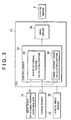
- FIG. 3 is a block diagram regarding the control of the electric motor 5 by the ECU 13.
- the ECU 13 includes a control circuit 31 that performs a predetermined calculation, and a drive circuit 32 that controls the supply of power to the electric motor 5.
- the control circuit 31 includes a rotor rotational position calculating portion 33 that calculates the rotational position (absolute position) of the rotor 21, and a target current value calculating portion 34 that calculates a target value of the current supplied to the electric motor 5.
- the rotational position ⁇ o of the output shaft 9 may be calculated based on the rotational position ⁇ i of the input shaft 8 and the steering torque T.
- the rotor 21 and the output shaft 9 are coupled to each other so as to be rotatable together. Therefore, the rotational position of the rotor 21 may be calculated by calculating the rotational position ⁇ o of the output shaft 9.
- the target current value calculating portion 34 calculates a magnitude of a steering assistance force transmitted from the electric motor 5 to the output shaft 9 (an output torque of the electric motor 5) based on a steering torque input from the torque sensor 12, a vehicle speed input from the vehicle speed sensor 30, and the like. The target current value calculating portion 34 then calculates a target current value proportional to the calculated magnitude of the steering assistance force.
- the rotational position of the rotor 21 calculated by the rotor rotational position calculating portion 33 and the target current value calculated by the target current value calculating portion 34 are input to the drive circuit 32.
- the drive circuit 32 then supplies the electric motor 5 with a current of the target current value through, for example, pulse-width modulation (PWM) control. More specifically, a semiconductor switching element such as, for example, a field-effect transistor (FET) or the like is changed over between its ON state and its OFF state based on the rotational position of the rotor 21, and the energization state of the coils 26 is thereby controlled.
- PWM pulse-width modulation
- the value of the current supplied to the electric motor 5 is detected by a current sensor (not shown), and the value of the current supplied to the electric motor 5 is corrected based on the detected current.
- the value of the current supplied to the electric motor 5 is thereby controlled to the target current value.
- the steering assist force of the magnitude calculated by the target current value calculating portion 34 is transmitted to the output shaft 9.
- the rotational position of the rotor 21 is detected by the input shaft rotational position sensor 18, the torque sensor 12, and the ECU 13. That is, in this embodiment, there is no need to provide a device such as a resolver or the like to detect the rotational position of the rotor inside the electric motor. Therefore, the size of the electric motor 5 in the axial direction X1 may be reduced.
- the input shaft rotational position sensor 18 for detecting the rotational position of the lower shaft 7, which constitutes a part of the input shaft, is disposed above the electric motor 5 in the axial direction X1 and in the hollow, annular space S between the lower shaft 7 and the lower column 15. This arrangement utilizes the available space more efficiently and allows further reductions in the size of the electric power steering device 1 in the axial direction X1.
- the rotational position of the rotor 21 is calculated using equation (4).
- the rotational position of the rotor 21 may be calculated using any suitable method.
- the rotational position of the rotor 21 may be calculated using a different equation, and a known torque sensor other than the aforementioned torque sensor may be employed as the torque sensor 12.
- the rotational position of the rotor 21 is calculated with ease.
- the rotational position of the lower shaft 7 is detected by the input shaft rotational position sensor18.
- the input shaft rotational position sensor 18 may be disposed around the upper shaft 6 to detect the rotational position (absolute position) of the upper shaft 6. That is, it is appropriate for the input shaft rotational position detecting unit 18 to detect the rotational position of one of the shafts constituting the input shaft (the upper shaft 6, the lower shaft 7, or the input shaft 8). If a steering member rotational position sensor (corresponding to a steering angle sensor) for detecting the rotational position of the steering member 2 is provided, there is no need to provide the input shaft rotational position sensor 18. That is, the above-described steering member rotational position sensor may be employed as input shaft rotational position sensor.
- the invention is not limited to this example.
- the invention may be applied to another vehicular steering device such as an electric power steering device of so-called pinion assist type or the like.
- FIG. 4 is a cross-sectional view showing the schematic construction of the electric power steering device 1 according to a second embodiment of the invention. The contents identical to those of the first embodiment of the invention will not be described below.
- the sensor housing 16 includes a tubular portion 50, and an annular flange portion 51 extended radially outward on the lower end of the tubular portion 50.
- the torque sensor 12 is accommodated in the tubular portion 50 along an inner periphery thereof.
- the flange portion 51 is coupled to the motor housing 23 of the electric motor 5.
- FIG. 5 is an enlarged view of part of FIG. 4 around the electric motor 5.
- the electric motor 5 according to this embodiment is a brushless motor of so-called inner rotor type.
- the electric motor 5 is equipped with the annular rotor 21 provided coaxially with the steering shaft 3, the annular stator 22 surrounding the rotor 21, and the motor housing 23 for accommodating the rotor 21 and the stator 22.
- the rotor 21 is constructed by annularly combining a plurality of permanent magnets.
- the outer periphery of the rotor 21 has a magnetic pole alternately serving as a north pole and a south pole.
- the rotor 21 is coupled to the outer peripheral face of a tubular portion 55, which constitutes a part of the output shaft 9. That is, the output shaft 9 includes a first shaft 90 and a second shaft 91.
- the second shaft 91 includes the tubular portion 55, which is equal in length to the rotor 21 with respect to the axial direction X1, an annular stage portion 56 extended radially inward of the tubular portion 55 from a lower end thereof, and a shaft portion 57 extending downward from a central portion of the annular stage portion 56.
- the tubular portion 55, the annular stage portion 56, and the shaft portion 57 are coaxially disposed.
- the rotor 21 is coaxially coupled to the outer peripheral face of the tubular portion 55 such that the rotor 21 and the tubular portion 55 can rotate together.
- the lower end 90a of the first shaft 90 is located inside an inner periphery of the top end of the tubular portion 55.
- the lower end 90a of the first shaft 90 and the tubular portion 55 are coupled to each other via an annular intermediate member 58 such that the first shaft 90 and the tubular portion 55 can rotate together. That is, the rotor 21 and the first shaft 90 are coupled to each other so as to be rotatable together via the intermediate member 58 and the tubular portion 55.
- a hollow space may be formed along the inner periphery of the tubular portion 55. Thus, weight of the electric motor 5 is reduced.
- the stator 22 includes the annular stator core 25, and the plurality of the coils 26 wound around the stator core 25.
- the stator core 25 surrounds the rotor 21 in a radially spaced manner.
- the stator core 25 includes an annular yoke and a plurality of teeth that protrude radially inward from the inner periphery of the yoke (not shown).
- the plurality of the coils 26 are wound around the plurality of the teeth respectively.
- Each coil 26 is supplied with power from a power supply source (not shown).
- the supply of power to each coil 26 is controlled by an ECU. When the ECU causes the power supply source to supply each coil 26 with power, a rotational torque is thereby transmitted from the rotor 21 to the output shaft 9. As a result, steering assist is provided to the driver.
- the motor housing 23 includes a tubular main body portion 61 that has the inner periphery to which the stator 22 is fixed, and an end member 62 fixed to a lower end of the main body portion 61.
- the motor housing 23 is mounted on the vehicle via a lower fixing bracket 34 fixed to a fixing portion 33 of the vehicle, and an intermediate member 36 rotatably supported by the lower fixing bracket 34 via a tilt strut 35.
- the main body portion 61 may be formed by, for example, plastically deforming a thin steel plate through pressing or the like.
- the main body portion 61 is equipped with a tubular portion 67 whose axial length is longer than the stator core 25, and an annular flange 68 that extends radially outward on the lower end of the tubular portion 67.
- the stator 22 may be, for example, press-fitted on an inner periphery of the tubular portion 67, and coaxially fixed to an axially intermediate region of the tubular portion 67.
- the flange portion 51 of the sensor housing 16 is fixed to an upper end of the tubular portion 67.
- the flange portion 51 includes an annular plate portion 69 that extends radially outward from the lower end of the tubular portion 50 of the sensor housing 16, and a tubular protrusion 70 that extends downward from the annular plate portion 50 at a position close to an outer periphery thereof.
- the flange portion 51 may be fixed to the upper end of the tubular portion 67.
- the tubular protrusion 70 of the sensor housing 16 is fitted to the tubular portion 67 of the motor housing 23, and holds a resolver stator 71 on an inner periphery thereof.
- a resolver for detecting the rotational position of the rotor 21 is constructed of this resolver stator 71 and a resolver rotor 73 held by an annular plate portion 72 of the first shaft 90.
- the resolver stator 71 and the resolver rotor 73 are separated by a gap, and the resolver stator 71 surrounds the resolver rotor 73.
- the rotational position sensor is not limited to the resolver. Any suitable sensor, such as a rotary encoder or the like, may be employed as the rotational position sensor.
- the electric motor 5 may be designed not only as a brushless motor of so-called inner rotor type but also as a brushless motor of so-called outer rotor type or a non-brushless motor.
- the end member 62 is a metal member formed by, for example, casting or cutting, and is thicker than the tubular portion 67. That is, the end member 62 includes an annular plate portion 74 that is thicker than the tubular portion 67 and fixed to the flange 68; an inner tube 75 that is thicker than the tubular portion 67 and that extends axially upward from the annular plate portion 74 at a position close to an inner periphery of the annular plate portion 74; and an outer tube 76 that extends axially upward from the annular plate portion 74 at a position toward the outer periphery of the annular plate portion 74.
- the inner tube 75 and the outer tube 76 are disposed coaxially with each other, and the end member 62 is formed of a material containing, for example, aluminum to reduce weight.
- a region 74a of the annular plate portion 74 that is located radially outward of the outer tube 76 has substantially the same contour as the flange 68.
- the output shaft 9 is inserted through ⁇ a central hole of the annular plate portion 74.
- the end member 62 is attached to the main body portion 61 from below such that the region 74a of the annular plate portion 74 is superposed on the annular flange 68.
- the region 74a of the annular plate portion 74 and the flange 68 are fixed to each other by a plurality of fixing screws 78 and 79.
- the fixing screws 78 and 79 are inserted through screw-holes formed in the region 74a of the annular plate portion 74 and the flange portion 68 in the axial direction X1. Fastened together by these fixing screws 78 and 79, the region 74a of the annular plate portion 74 and the flange 68 are fixed to each other.
- the intermediate member 36, rotatably supported by the lower fixing bracket 34, is fixed to the annular plate portion 74.
- the intermediate member 36, the region 74a of the annular plate portion 74, and the flange 68 are fastened together and fixed to one another by the common fixing screw 78, whose shaft portion is inserted through these three components 36, 74a, and 68 in the axial direction X1.
- the intermediate member 36 includes a plate portion 80 fixed to the annular plate portion 74, and a supported portion 81 rotatably supported via the tilt strut 35.
- the plate portion 80 is fixed to part of the annular plate portion 74 and superposed on the annular plate portion 74 in the axial direction X1.
- the outer tube 76 is fitted in the tubular portion 67 at the lower end of the tubular portion 67. Because the outer tube 76 is fitted in the tubular portion 67 at the lower end of the tubular portion 67, the end member 62 is accurately positioned with respect to the tubular portion 67. That is, the inner peripheral face of the inner tube 75 is coaxially disposed with the inner peripheral face of the tubular portion 67.
- a bearing holding portion 75a that holds a bearing 84 is provided on the inner peripheral face of the inner tube 75.
- the end member 62 rotatably supports the shaft portion 57 of the output shaft 9 via the bearing 84 held by the bearing holding portion 75a.
- the end member 62 rotatably supports the output shaft 9 via the bearing 84, and rotatably supports the rotor 21 via the bearing 84 and the output shaft 9.
- the end member 62 can stably hold the bearing 84 and the output shaft 9, and can rotatably support the output shaft 9 stably.
- the end member 62 as part of the motor housing 23 is thicker than the tubular portion 67. Therefore, an end member 62 of sufficient strength is ensured that can stably support the output shaft 9 via the bearing 84. Accordingly, the wobbling of the output shaft 9 or the occurrence of vibrations or noise resulting from the wobbling of the output shaft 9 is prevented.
- Part of the end member 62 (the region 74a of the annular plate portion 74) is reinforced by being sandwiched by the intermediate member 36 and the flange 68 in the axial direction X1. Therefore, the bearing 84 and the output shaft 9 are more stably held by the end member 62. Thus, the wobbling of the output shaft 9 and the occurrence of vibrations or noise resulting from the wobbling of the output shaft 9 is more reliably prevented.
- the weight and thickness of the tubular portion 67 is reduced.
- the tubular portion 67 is thinner than the end member 62, but is reinforced by the stator 22, which is fixed to the inner periphery the tubular portion 67. Therefore, an electric motor 5 of sufficient strength as a whole is provided.
- the tubular portion 67 may be thin, but is formed of the material (steel plate) containing iron, which exhibits a relatively high strength. Therefore, a tubular portion 67 of sufficient strength is provided.
- the distance between the rotor 21 and the stator 22 in a radial direction of the electric motor 5 (a so-called air gap) may be reduced as well. That is, by preventing the wobbling of the output shaft 9 rotating together with the rotor 21, the wobbling of the rotor 21 may also be prevented. Thus, it is possible to prevent the the rotor 21 from colliding with the stator 22 despite the narrow air gap. By reducing the air gap, the output of the electric motor 5 may be enhanced.
- the example in which the end member 62 is fastened by the fixing screws 78 and 79 to the main body portion 61 is described.
- this is not the only method for fixing the end member 62 to the main body portion 61.
- the end member 62 may be fixed to the main body portion 61 by any suitable method such as welding, press-fitting, adhesives, or the like.
- the rotational position of the rotor is calculated based on the detected rotational position of the input shaft and the detected steering torque.
- the construction having the thick end member fixed to the end of the motor housing is described.
- the invention is not limited to the described embodiments.
- the second embodiment may be modified by disposing the input shaft rotational position sensor on the inner periphery of the lower column instead of the inner periphery of the motor housing and the rotational position of the rotor may be calculated based on the rotational position of the input shaft and the steering torque may be combined with the rotational position of the input shaft.
- FIG. 6 is a cross-sectional view showing the schematic construction of the electric power steering device 1 according to the modified second embodiment of the invention.
- a steering shaft (3) is composed of an upper shaft (6), a lower shaft (7), an input shaft (8), and an output shaft (9).
- the upper shaft (6), the lower shaft (7), and the input shaft (8) can rotate together, and the input shaft (8) and the output shaft (9) are relatively rotatably coupled to each other via a torsion bar (11).
- the rotational position of a rotor (21) coupled to the output shaft (9) is calculated based on the detected rotational position of the lower shaft (7) and a steering torque detected based on the amount of relative rotational displacement of the input shaft (8) and the output shaft (9).
Landscapes
- Engineering & Computer Science (AREA)
- Chemical & Material Sciences (AREA)
- Combustion & Propulsion (AREA)
- Transportation (AREA)
- Mechanical Engineering (AREA)
- Power Steering Mechanism (AREA)
- Steering Control In Accordance With Driving Conditions (AREA)
Claims (7)
- Elektrische Lenkhilfevorrichtung mit einer Eingangswelle (6, 7) mit einem ersten Ende und einem zweiten Ende, einem Lenkbauteil (2), das an dem ersten Ende der Eingangswelle angebracht ist, einer Ausgangswelle (9), die über einen Torsionsstab (11) an das zweite Ende der Eingangswelle gekoppelt ist, und einem Elektromotor (5), der einen Lenkhilfe erbringt und einen Rotor (21) aufweist, der an der Ausgangswelle koaxial montiert ist und der sich zusammen mit der Ausgangswelle dreht, mit:einem Lenkmomentsensor (12), der ein Lenkmoment basierend auf einem Betrag eines relativen Drehversatzes zwischen der Eingangswelle und der Ausgangswelle erfasst;einem Eingangswellendrehpositionssensor (18), der eine Drehposition der Eingangswelle erfasst; und gekennzeichnet ist, durcheine Rotordrehpositionsberechnungseinheit (33), die eine Drehposition des Rotors basierend auf der erfassten Drehposition der Eingangswelle und dem erfassten Lenkmoment berechnet.
- Elektrische Lenkhilfevorrichtung gemäß Anspruch 1, wobei der Eingangswellendrehpositionssensor (18) der Eingangswelle (6, 7) in einer radialen Richtung von dieser zugewandt ist.
- Elektrische Lenkhilfevorrichtung gemäß Anspruch 1 oder 2, ferner mit:einer ringförmigen Lenksäule (4), die die Eingangswelle aufnimmt und drehbar stützt, wobeider Eingangswellendrehpositionssensor zwischen einer Außenumfangsfläche der Eingangswelle (6, 7) und einer Innenumfangsfläche der ringförmigen Lenksäule (4) angeordnet ist.
- Elektrische Lenkhilfevorrichtung gemäß Anspruch 3, wobei der Eingangswellendrehpositionssensor einen Sensorrotor (19) und einen Stator aufweist, und der Sensorrotor an der Außenumfangsfläche der Eingangswelle befestigt ist und der Stator (20) an der Innenumfangsfläche der Lenksäule befestigt ist und den Sensorrotor umgibt.
- Elektrische Lenkhilfevorrichtung gemäß einem der Ansprüche 1 bis 4, ferner mit:einem ringförmigen Motorgehäuse (23), das den Elektromotor aufnimmt, wobeider Außendurchmesser der Lenksäule (4) kleiner als der Außendurchmesser des ringförmigen Motorgehäuses (23) ist.
- Elektrische Lenkhilfevorrichtung gemäß einem der Ansprüche 1 bis 5, ferner mit:einem ringförmigen Sensorgehäuse (16), das den Lenkmomentsensor (12) aufnimmt, wobeider Lenkmomentsensor in einer axialen Richtung der Eingangswelle zwischen dem Eingangswellendrehpositionssensor und dem Elektromotor angeordnet ist, undder Außendurchmesser des ringförmigen Sensorgehäuses (16) kleiner als der Außendurchmesser des ringförmigen Motorgehäuses (23) ist.
- Elektrische Lenkhilfevorrichtung gemäß Anspruch 1, wobei der Elektromotor den Rotor und einen Stator aufweist, der dem Rotor radial zugewandt ist, und
ein Motorgehäuse (23) aufweist, das den Rotor und den Stator aufnimmt, wobei das Motorgehäuse einen röhrenartigen Abschnitt (55), der eine Umfangswand hat, an der der Stator (25) befestigt ist, und ein Endbauteil (62) aufweist, das an einem Ende des röhrenartigen Abschnitts befestigt ist und einen Lagerhalteabschnitt aufweist, wobei eine Dicke des Endbauteils in der axialen Richtung des röhrenartigen Abschnitts dicker als eine Dicke der Umfangswand des röhrenartigen Abschnitts in einer radialen Richtung des röhrenartigen Abschnitts ist, und wobei die Lenkwelle durch ein Lager, das durch den Lagerhalteabschnitt (84) gehalten wird, drehbar gestützt ist.
Applications Claiming Priority (2)
| Application Number | Priority Date | Filing Date | Title |
|---|---|---|---|
| JP2007123695A JP5013180B2 (ja) | 2007-05-08 | 2007-05-08 | 車両用操舵装置 |
| JP2007160219A JP2008308118A (ja) | 2007-06-18 | 2007-06-18 | 電動パワーステアリング装置 |
Publications (3)
| Publication Number | Publication Date |
|---|---|
| EP1990256A2 EP1990256A2 (de) | 2008-11-12 |
| EP1990256A3 EP1990256A3 (de) | 2010-01-06 |
| EP1990256B1 true EP1990256B1 (de) | 2011-06-15 |
Family
ID=39680999
Family Applications (1)
| Application Number | Title | Priority Date | Filing Date |
|---|---|---|---|
| EP08155269A Not-in-force EP1990256B1 (de) | 2007-05-08 | 2008-04-28 | Elektrische Servolenkung |
Country Status (2)
| Country | Link |
|---|---|
| US (1) | US8066094B2 (de) |
| EP (1) | EP1990256B1 (de) |
Cited By (1)
| Publication number | Priority date | Publication date | Assignee | Title |
|---|---|---|---|---|
| CN109760740A (zh) * | 2018-12-30 | 2019-05-17 | 山东汇川汽车部件有限公司 | 一种直流永磁力矩电机直驱式电动助力转向装置 |
Families Citing this family (4)
| Publication number | Priority date | Publication date | Assignee | Title |
|---|---|---|---|---|
| JP2008284912A (ja) * | 2007-05-15 | 2008-11-27 | Jtekt Corp | 車両用操舵装置 |
| DE102013223380A1 (de) * | 2013-01-10 | 2014-07-10 | Ford Global Technologies, Llc | Elektrische Servolenkung für Fahrzeuge |
| CN116215645A (zh) * | 2017-04-17 | 2023-06-06 | 吉林大学 | 一种助力转向与独立驱动集成式轮边电驱动装置的控制方法 |
| CN107010105B (zh) * | 2017-04-17 | 2023-12-15 | 吉林大学 | 一种线控转向与独立驱动集成式轮边电驱动装置 |
Family Cites Families (22)
| Publication number | Priority date | Publication date | Assignee | Title |
|---|---|---|---|---|
| US4715461A (en) * | 1985-01-22 | 1987-12-29 | Honda Giken Kogyo Kabushiki Kaisha | Electric power steering system for vehicles |
| US5919241A (en) * | 1996-12-13 | 1999-07-06 | General Motors Corporation | Vehicle having electric power steering with active damping |
| US6050360A (en) * | 1998-06-24 | 2000-04-18 | General Motors Corporation | Apparatus and method for producing a desired return torque in a vehicle power steering system having a rotational steering position sensor |
| US20020124663A1 (en) * | 1999-04-07 | 2002-09-12 | Yoshitomo Tokumoto | Rotational angle detecting device, torque detecting device and steering apparatus |
| DE10033810B4 (de) * | 2000-07-12 | 2005-10-27 | Daimlerchrysler Ag | Lenksäule eines Kraftfahrzeuges |
| JP3593050B2 (ja) * | 2001-03-27 | 2004-11-24 | 三菱電機株式会社 | 位置検出装置の異常検出方法および装置並びに電動パワーステアリング装置 |
| JP3758563B2 (ja) * | 2001-12-04 | 2006-03-22 | 豊田工機株式会社 | 位置検出器の補正方法、及び、電気式動力舵取装置 |
| JP2004001626A (ja) | 2002-05-31 | 2004-01-08 | Koyo Seiko Co Ltd | 電動パワーステアリング装置 |
| DE10253465A1 (de) * | 2002-06-22 | 2004-01-22 | Zf Lenksysteme Gmbh | Lenksystem für ein Fahrzeug |
| DE60319045T2 (de) * | 2002-10-24 | 2009-02-05 | Jtekt Corporation | Lenkwinkelsensor für eine elektrische Servolenkung |
| DE10255751A1 (de) * | 2002-11-28 | 2004-06-09 | Leopold Kostal Gmbh & Co Kg | Elektrische Lenkkraftunterstützungseinrichtung |
| JP3847702B2 (ja) * | 2002-12-02 | 2006-11-22 | 株式会社ジェイテクト | 車両の操舵制御装置 |
| DE60213436T2 (de) * | 2002-12-20 | 2007-03-01 | Ford Global Technologies, LLC, Dearborn | Regelungsstrategie für rechnergeregelte Lenkung |
| JP4525283B2 (ja) * | 2003-10-21 | 2010-08-18 | 株式会社ジェイテクト | 電動パワーステアリング装置 |
| JP4474896B2 (ja) * | 2003-10-22 | 2010-06-09 | 株式会社ジェイテクト | パワーステアリング装置 |
| JP4230348B2 (ja) * | 2003-12-22 | 2009-02-25 | 株式会社デンソー | 回転検出装置 |
| JP4161074B2 (ja) * | 2004-02-02 | 2008-10-08 | 三菱電機株式会社 | 電動式パワーステアリング装置 |
| JP4600653B2 (ja) * | 2004-10-28 | 2010-12-15 | 株式会社ジェイテクト | 操舵制御装置 |
| US7295907B2 (en) * | 2005-06-14 | 2007-11-13 | Trw Automotive U.S. Llc | Recovery of calibrated center steering position after loss of battery power |
| RU2278797C1 (ru) * | 2005-08-19 | 2006-06-27 | Открытое акционерное общество "Калужский завод электронных изделий" | Электромеханический усилитель руля автомобиля и электродвигатель для усилителя руля |
| EP1777806A2 (de) * | 2005-10-21 | 2007-04-25 | NSK Ltd. | Steuervorrichtung des elektrischen Antriebs und elektrische Servolenkung |
| US7538514B2 (en) * | 2007-04-25 | 2009-05-26 | Delphi Technologies, Inc. | Systems and methods for controlling torque of a motor |
-
2008
- 2008-04-28 EP EP08155269A patent/EP1990256B1/de not_active Not-in-force
- 2008-04-30 US US12/112,439 patent/US8066094B2/en not_active Expired - Fee Related
Cited By (1)
| Publication number | Priority date | Publication date | Assignee | Title |
|---|---|---|---|---|
| CN109760740A (zh) * | 2018-12-30 | 2019-05-17 | 山东汇川汽车部件有限公司 | 一种直流永磁力矩电机直驱式电动助力转向装置 |
Also Published As
| Publication number | Publication date |
|---|---|
| EP1990256A2 (de) | 2008-11-12 |
| EP1990256A3 (de) | 2010-01-06 |
| US8066094B2 (en) | 2011-11-29 |
| US20080277193A1 (en) | 2008-11-13 |
Similar Documents
| Publication | Publication Date | Title |
|---|---|---|
| EP1810910B1 (de) | Motor und Servolenkungsvorrichtung | |
| EP2053725B1 (de) | Vorrichtung zur Erfassung des Motordrehwinkels | |
| US20090266640A1 (en) | Electric power steering apparatus | |
| JP4784828B2 (ja) | 車両用操舵装置 | |
| EP2256016B1 (de) | Fahrzeuglenkvorrichtung | |
| JP2002079949A (ja) | 電動パワーステアリング装置 | |
| EP2832626B1 (de) | Elektrische servolenkvorrichtung | |
| EP1990256B1 (de) | Elektrische Servolenkung | |
| EP1995152A2 (de) | Fahrzeuglenkung | |
| EP1985521A2 (de) | Energieaufnehmendes Lenksystem | |
| JP2007331428A (ja) | 電動モータ及び電動パワーステアリング装置 | |
| JP2009001243A (ja) | 電動パワーステアリング装置 | |
| JP2007290550A (ja) | 電動パワーステアリング装置 | |
| EP1862373A1 (de) | Motor und elektrisches Servolenksystem | |
| JP2000190857A (ja) | 電動式パワ―ステアリング装置 | |
| JP5158415B2 (ja) | 電動パワーステアリング装置 | |
| JP5013180B2 (ja) | 車両用操舵装置 | |
| JP4235894B2 (ja) | 電動パワーステアリング装置 | |
| JP2008213587A (ja) | 車両用操舵装置 | |
| JP2008279809A (ja) | 電動パワーステアリング装置 | |
| JP2001213333A (ja) | 動力舵取装置 | |
| JP2009001242A (ja) | 電動パワーステアリング装置 | |
| JP2010188887A (ja) | 車両用操舵装置 | |
| JP2010149596A (ja) | 電動式パワーステアリング装置 | |
| JP2009241788A (ja) | 車両用操舵装置 |
Legal Events
| Date | Code | Title | Description |
|---|---|---|---|
| PUAI | Public reference made under article 153(3) epc to a published international application that has entered the european phase |
Free format text: ORIGINAL CODE: 0009012 |
|
| AK | Designated contracting states |
Kind code of ref document: A2 Designated state(s): AT BE BG CH CY CZ DE DK EE ES FI FR GB GR HR HU IE IS IT LI LT LU LV MC MT NL NO PL PT RO SE SI SK TR |
|
| AX | Request for extension of the european patent |
Extension state: AL BA MK RS |
|
| PUAL | Search report despatched |
Free format text: ORIGINAL CODE: 0009013 |
|
| AK | Designated contracting states |
Kind code of ref document: A3 Designated state(s): AT BE BG CH CY CZ DE DK EE ES FI FR GB GR HR HU IE IS IT LI LT LU LV MC MT NL NO PL PT RO SE SI SK TR |
|
| AX | Request for extension of the european patent |
Extension state: AL BA MK RS |
|
| 17P | Request for examination filed |
Effective date: 20100706 |
|
| AKX | Designation fees paid |
Designated state(s): DE FR |
|
| GRAP | Despatch of communication of intention to grant a patent |
Free format text: ORIGINAL CODE: EPIDOSNIGR1 |
|
| GRAS | Grant fee paid |
Free format text: ORIGINAL CODE: EPIDOSNIGR3 |
|
| RIN1 | Information on inventor provided before grant (corrected) |
Inventor name: HIGASHI, KENJI, C/O JTEKT CORPORATION Inventor name: NAKANO, SHIRO, C/O JTEKT CORPORATION Inventor name: YOSHIOKA, KAZUYA, C/O JTEKT CORPORATION Inventor name: YOSHII, YASUYUKI, C/O JTEKT CORPORATION Inventor name: NAKA, MASAMI, C/O JTEKT CORPORATION Inventor name: JIMBO, SHIMON, C/O JTEKT CORPORATION |
|
| GRAA | (expected) grant |
Free format text: ORIGINAL CODE: 0009210 |
|
| AK | Designated contracting states |
Kind code of ref document: B1 Designated state(s): DE FR |
|
| REG | Reference to a national code |
Ref country code: DE Ref legal event code: R096 Ref document number: 602008007568 Country of ref document: DE Effective date: 20110804 |
|
| PLBE | No opposition filed within time limit |
Free format text: ORIGINAL CODE: 0009261 |
|
| STAA | Information on the status of an ep patent application or granted ep patent |
Free format text: STATUS: NO OPPOSITION FILED WITHIN TIME LIMIT |
|
| 26N | No opposition filed |
Effective date: 20120316 |
|
| REG | Reference to a national code |
Ref country code: DE Ref legal event code: R097 Ref document number: 602008007568 Country of ref document: DE Effective date: 20120316 |
|
| PGFP | Annual fee paid to national office [announced via postgrant information from national office to epo] |
Ref country code: DE Payment date: 20140430 Year of fee payment: 7 Ref country code: FR Payment date: 20140409 Year of fee payment: 7 |
|
| REG | Reference to a national code |
Ref country code: DE Ref legal event code: R119 Ref document number: 602008007568 Country of ref document: DE |
|
| PG25 | Lapsed in a contracting state [announced via postgrant information from national office to epo] |
Ref country code: DE Free format text: LAPSE BECAUSE OF NON-PAYMENT OF DUE FEES Effective date: 20151103 |
|
| REG | Reference to a national code |
Ref country code: FR Ref legal event code: ST Effective date: 20151231 |
|
| PG25 | Lapsed in a contracting state [announced via postgrant information from national office to epo] |
Ref country code: FR Free format text: LAPSE BECAUSE OF NON-PAYMENT OF DUE FEES Effective date: 20150430 |