EP1983590A2 - Procédé de commande d'un dispositif de commande - Google Patents
Procédé de commande d'un dispositif de commande Download PDFInfo
- Publication number
- EP1983590A2 EP1983590A2 EP08154797A EP08154797A EP1983590A2 EP 1983590 A2 EP1983590 A2 EP 1983590A2 EP 08154797 A EP08154797 A EP 08154797A EP 08154797 A EP08154797 A EP 08154797A EP 1983590 A2 EP1983590 A2 EP 1983590A2
- Authority
- EP
- European Patent Office
- Prior art keywords
- electro
- mechanical transducer
- constant
- vibration friction
- moving
- Prior art date
- Legal status (The legal status is an assumption and is not a legal conclusion. Google has not performed a legal analysis and makes no representation as to the accuracy of the status listed.)
- Withdrawn
Links
- 238000000034 method Methods 0.000 title claims description 33
- 230000008602 contraction Effects 0.000 claims abstract description 46
- 230000001133 acceleration Effects 0.000 claims description 44
- 238000006073 displacement reaction Methods 0.000 description 41
- 230000003287 optical effect Effects 0.000 description 12
- 230000008901 benefit Effects 0.000 description 4
- 239000000463 material Substances 0.000 description 4
- 239000000853 adhesive Substances 0.000 description 2
- 229910052451 lead zirconate titanate Inorganic materials 0.000 description 2
- 229920000049 Carbon (fiber) Polymers 0.000 description 1
- 229920000106 Liquid crystal polymer Polymers 0.000 description 1
- 239000004977 Liquid-crystal polymers (LCPs) Substances 0.000 description 1
- 239000004917 carbon fiber Substances 0.000 description 1
- 230000000295 complement effect Effects 0.000 description 1
- 239000000805 composite resin Substances 0.000 description 1
- 239000000470 constituent Substances 0.000 description 1
- 230000008878 coupling Effects 0.000 description 1
- 238000010168 coupling process Methods 0.000 description 1
- 238000005859 coupling reaction Methods 0.000 description 1
- 230000000593 degrading effect Effects 0.000 description 1
- 230000002542 deteriorative effect Effects 0.000 description 1
- 230000005489 elastic deformation Effects 0.000 description 1
- 238000010030 laminating Methods 0.000 description 1
- HFGPZNIAWCZYJU-UHFFFAOYSA-N lead zirconate titanate Chemical compound [O-2].[O-2].[O-2].[O-2].[O-2].[Ti+4].[Zr+4].[Pb+2] HFGPZNIAWCZYJU-UHFFFAOYSA-N 0.000 description 1
- 239000002184 metal Substances 0.000 description 1
- 229910052751 metal Inorganic materials 0.000 description 1
- 239000007769 metal material Substances 0.000 description 1
- 229910044991 metal oxide Inorganic materials 0.000 description 1
- 150000004706 metal oxides Chemical class 0.000 description 1
- 230000002093 peripheral effect Effects 0.000 description 1
- 239000011347 resin Substances 0.000 description 1
- 229920005989 resin Polymers 0.000 description 1
- 239000004065 semiconductor Substances 0.000 description 1
- 230000003068 static effect Effects 0.000 description 1
- 239000000758 substrate Substances 0.000 description 1
Images


Classifications
-
- H—ELECTRICITY
- H02—GENERATION; CONVERSION OR DISTRIBUTION OF ELECTRIC POWER
- H02N—ELECTRIC MACHINES NOT OTHERWISE PROVIDED FOR
- H02N2/00—Electric machines in general using piezoelectric effect, electrostriction or magnetostriction
- H02N2/02—Electric machines in general using piezoelectric effect, electrostriction or magnetostriction producing linear motion, e.g. actuators; Linear positioners ; Linear motors
- H02N2/021—Electric machines in general using piezoelectric effect, electrostriction or magnetostriction producing linear motion, e.g. actuators; Linear positioners ; Linear motors using intermittent driving, e.g. step motors, piezoleg motors
- H02N2/025—Inertial sliding motors
-
- H—ELECTRICITY
- H02—GENERATION; CONVERSION OR DISTRIBUTION OF ELECTRIC POWER
- H02N—ELECTRIC MACHINES NOT OTHERWISE PROVIDED FOR
- H02N2/00—Electric machines in general using piezoelectric effect, electrostriction or magnetostriction
- H02N2/02—Electric machines in general using piezoelectric effect, electrostriction or magnetostriction producing linear motion, e.g. actuators; Linear positioners ; Linear motors
- H02N2/06—Drive circuits; Control arrangements or methods
- H02N2/065—Large signal circuits, e.g. final stages
- H02N2/067—Large signal circuits, e.g. final stages generating drive pulses
Definitions
- This invention relates to a driving device (a linear actuator) and, in particular, to a driving method for driving a driving device where an electro-mechanical transducer such a piezoelectric element is used as a driving source of the driving device (the linear actuator).
- linear actuators driving devices
- electro-mechanical transducers such as piezoelectric elements, electrostrictive elements, magnetrostrictive elements, or the like are used as auto-focus actuators or zoom actuators for use in cameras.
- JP-B 2633066 (which will be also called a first patent document), which corresponds to U.S. Pat. No. 5,225,941 , discloses a driving device comprising a driving rod frictionally engaged with a lens barrel, a piezoelectric element disposed in contact with the driving rod, and a leaf spring for bringing the driving rod into frictional engagement with the lens barrel. That is, the driving rod is bonded to an end of the piezoelectric element in an expansion direction.
- the lens barrel is movably supported to the driving rod.
- the leaf spring produces friction between the driving rod and the lens barrel.
- a voltage is applied to the piezoelectric element so as to make a speed of expansion of the piezoelectric element different from a speed of contraction thereof.
- JP-B 3218851 (which will be also called a second patent document), which corresponds to U.S. Pat. No. 5,589,723 , discloses a driving apparatus comprising a piezoelectric element, a driving member (a driving shaft), coupled to the piezoelectric element, for extending in an expansion direction of the piezoelectric element, and a driven member (a moving member, a lens barrel) having a friction member frictionally coupled to the driving member (the driving shaft).
- the driving apparatus in JP-B 3218851 drives the lens barrel by devising a driving signal applied to the piezoelectric element.
- JP-A 9-191665 discloses a linear drive mechanism using an electro-mechanical transducer which is insensitive to elastic deformation of a constituent member.
- the linear driving mechanism disclosed in JP-A 9-191665 comprises the electro-mechanical transducer, a working member which is fixedly connected to the electro-mechanical transducer and which displaces with the electro-mechanical transducer, a driving member frictionally coupled to the working member, a driven member coupled to the driving member, and a driving pulse generating arrangement for causing expansion/contraction displacement to the electro-mechanical transducer.
- an internal barrel is integratedly and fixedly attached to a fixed lens barrel.
- the internal barrel has extensions which are formed in a radial direction on part of the internal barrel.
- a drive shaft (a moving portion) arranged parallel to an optical axis is supported by bearings of the extensions so as be movable in the optical axis direction.
- a piezoelectric element (the electro-mechanical transducer) is disposed between the working member (a vibration friction portion) and the extension of the internal barrel.
- the top half of the working member touches the drive shaft and a pad is installed on the bottom half of the working member and exerts a force toward the drive shaft via a spring, such that the pad touches the bottom half of the working member.
- the working member and the pad are friction-bonded to the drive shaft via a suitable friction force.
- the working member is displaced, and the drive shaft is driven by friction contact with the working member together with a lens holder frame serving as the driven member.
- JP-A 2006-304529 discloses a high-performance drive device whose cost and weight can be reduced in comparison with a structure with a metal material, and for which a moving member of high rigidity is used without deteriorating the speed of movement and a drive force.
- the moving member is formed with a liquid crystal polymer including carbon fibers.
- the drive device disclosed in JP-A 2006-304529 comprises a piezoelectric element for expanding and contracting in response to an applied voltage, a drive shaft (a vibration friction portion) fixed to one end of the piezoelectric element in an expansion/contraction direction, the moving member (a moving portion) which is slidably and frictionally engaged with the drive shaft, and a weight (a stationary member) connected to another end of the piezoelectric element in the expansion/contraction direction.
- the drive device moves the moving member (the moving portion) along the drive shaft (the vibration friction portion).
- JP-B 3002890 discloses an ultrasonic linear motor which is simple in structure and which comprises a simple driving circuit.
- the ultrasonic linear motor disclosed in JP-B 3002890 comprises a fixed base (a stationary member), a piezoelectric element (an electro-mechanical transducer), a frictional member (a vibration friction portion), and a moving element (a moving portion).
- the electro-mechanical transducer has one end secured to the fixed base and another end mounted with the frictional member extending laterally over the piezoelectric element.
- the piezoelectric element carries out, in an expansion/contraction direction, an expansion/contraction motion which makes the frictional member an expansion/contraction motion.
- the moving element is movable in parallel with the expansion/contraction direction of the piezoelectric element.
- the moving element is brought into pressure contact with the frictional member.
- the piezoelectric element is applied with a voltage having a saw-tooth waveform so that moving speeds of to-and-fro movements are different from each other in the expansion/contraction motion.
- Fig. 10 is a waveform chart for use in describing a related art driving method of the driving devices disclosed in the first through the fifth patent documents.
- the abscissa represents a time instant and the ordinate represents a displacement.
- Wd(v) represents a displacement waveform of the vibration friction portion
- Wd(m) represents a displacement waveform of the moving portion.
- the related art driving method comprises changing speeds of vibrations of the electro-mechanical transducer on expanding and on contracting, making the vibration friction portion a sow-tooth displacement, and moving the moving portion.
- the electro-mechanical transducer In order to obtain the saw-tooth displacement to the vibration friction portion, the electro-mechanical transducer is applied with the voltage having the sow-tooth waveform.
- the electro-mechanical transducer by applying a voltage having a rectangular wave to the electro-mechanical transducer, it is necessary to obtain the sow-tooth displacement to the vibration friction portion due to a characteristic of a transfer function which is determined by structure of the driving device. Therefore, the structure of the driving device is closely related to a frequency where the sow-tooth displacement is obtained to the vibration friction portion.
- a driving method is for driving a driving device which includes an electro-mechanical transducer having first and second end portions opposite to each other in an expansion/contraction direction, a stationary member coupled to the first end portion of the electro-mechanical transducer, a vibration friction portion coupled to the second end portion of the electro-mechanical transducer, and a moving portion frictionally coupled to the vibration friction portion.
- the moving portion is movable in the expansion/contraction direction of the electro-mechanical transducer.
- the driving method includes equalizing a constant expanding speed of the electro-mechanical transducer with a constant contracting speed of the electro-mechanical transducer, and setting a constant rest time interval after one of contraction of the electro-mechanical transducer and expansion of the electro-mechanical transducer, thereby moving the moving portion in one of an expansion direction and a contraction direction of the electro-mechanical transducer.
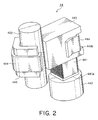
- Fig. 1 is an external perspective view of a driving device 20 to which a driving method according to a first exemplary embodiment of this invention is applicable.
- an orthogonal coordinate system (X, Y, Z) is used.
- an X-axis direction is a fore-and-aft direction (a depth direction)
- a Y-axis direction is a left-and-right direction (a width direction)
- a Z-axis direction is an up-and-down direction (a height direction).
- the up-and-down direction Z is a direction of an optical axis O of a lens.
- the driving device 20 is covered with a cabinet (not shown).
- the cabinet includes a cap-shaped upper cover (not shown) and a lower base (not shown).
- a stationary member (a weight) 442 which will later be described is mounted.
- the upper cover has an upper surface comprising a cylinder portion (not shown) having a center axis which is the optical axis O.
- the lower base had a central portion in which an image pickup device disposed on a substrate is mounted.
- the image pickup device picks up a subject image formed by an movable lens (which will later be described) to convert it into an electric signal.
- the image pickup device may, for example, comprise a CCD (charge coupled device) type image sensor, a CMOS (complementary metal oxide semiconductor) type image sensor, or the like.
- the illustrated driving device 20 comprises an auto-focus lens driving unit 40.
- a guide shaft (not shown) is disposed at a left and back side.
- the guide shaft extends in parallel with the optical axis O.
- the guide shaft has an upper end which is fixed to the upper surface of the upper cover of the cabinet and a lower end which is fixed to the lower base of the cabinet.
- a rod-shaped moving portion (a movable shaft) 423 which will later be described, is disposed at a right and front side which is opposite side with respect to the guide shaft. That is, the guide shaft and the moving shaft 423 are disposed at positions which are rotationally symmetric about the optical axis O.
- the auto-focus lens driving unit 40 comprises a lens movable portion 42 and a lens driving portion 44.
- the lens movable portion 42 includes a lens holding frame 421 for holding an auto-focus lens AFL which is the movable lens.
- the lens holding frame 421 is fixed on an upper portion of a movable barrel 422 having a substantially cylindrical shape.
- the movable barrel 422 comprises a pair of extending portions (however, an upper side thereof is only illustrated in Fig. 1 ) 4221 which extend in a radial direction outwards at the left and back side.
- the pair of extending portions 4221 have through holes 4221 a through which the above-mentioned guide shaft passes.
- the movable barrel 422 comprises a pair of extending portions 4222 which extend in the radial direction outwards at the right and front side.
- the pair of extending portions 4222 have fitting holes 4222a through which the rod-shaped movable shaft 423 passes and to which the rod-shaped moving shaft 423 is fixed.
- the lens movable portion 42 is movable in the direction of the optical axis O with respect to the cabinet.
- the lens driving portion 44 slidably supports the lens movable portion 42 in the direction of the optical axis O and drives the lens movable portion 42 in the manner which will later be described.
- Fig. 2 is a perspective view showing the lens driving portion 44 of the auto-focus lens driving unit 40 together with the rod-shaped moving shaft 423.
- Fig. 3 is a plan view showing the lens driving portion 44 of the auto-focus lens driving unit 40 together with the rod-shaped moving shaft 423.
- Fig. 4 is a perspective view showing a main portion of the lens driving portion 44.
- the lens driving portion 44 comprises a laminated piezoelectric element 441 serving as an electro-mechanical transducer, the stationary member (the weight) 442, and a vibration friction portion 443.
- the laminated piezoelectric element 441 expands and contracts in a direction of the optical axis O.
- the laminated piezoelectric element 441 has a structure where a plurality of piezoelectric layers are laminated in the direction of the optical axis O. As shown in Fig. 5 , the laminated piezoelectric element 441 has a first end portion (a lower end portion) 441 a and a second end portion (an upper end portion) 441 b which are disposed to each other in the expansion/contraction direction.
- the stationary member (the weight) 442 is coupled to the first end portion (the lower end portion) 441 a of the laminated piezoelectric element 441 using an adhesive agent or the like.
- the vibration friction portion 443 is coupled to the second end portion (the upper end portion) 441 b of the laminated piezoelectric element 441 using the adhesive agent or the like.
- a combination of the laminated piezoelectric element 441 and the static member 442 is called an piezoelectric unit.
- the rod-shaped moving shaft 423 is frictionally coupled to the vibration friction portion 443.
- the vibration friction portion 443 has a groove (a friction engagement surface) 443a which is a V-shape in cross section at a friction coupling portion between the vibration friction portion 443 and the rod-shaped moving shaft 423.
- the lens driving portion 44 comprises a spring 444 for pressing (urging) the rod-shaped moving shaft 423 against the vibration friction portion 443. That is, the spring 444 serves as an urging arrangement which is fixed to the vibration friction portion 443 and which generates a pressing force for pressing the moving shaft 423. Between the spring 444 and the rod-shaped moving shaft 423, a pad 445 having a V-shaped structure is sandwiched. The pad 445 is disposed so as to be opposed to the vibration friction portion 443 with the moving shaft 423 sandwiched therebetween. In the manner which is similar to the vibration friction portion 443, the pad 445 also has a groove 445a which is a V-shape in cross section at a contact portion between the pad 445 and the rod-shaped moving shaft 423.
- the vibration friction portion 443 has a groove 443b for holding the spring 444.
- the spring 444 has a first end portion which is engaged with the vibration friction portion 443 at the groove 443b and a second end portion which extends towards the moving shaft 423. Therefore, the vibration friction portion 443 and the pad 445 are pressed against the rod-shaped moving shaft 423 by the spring 444. As a result, the rod-shaped moving shaft 423 is frictionally coupled to the vibration friction portion 443 with stability.
- the pad 445 is sandwiched between the moving portion 423 and the spring 444.
- the pad 445 is for preventing the pressing force of the spring 444 from degrading due to the wearing away of friction thereof and for preventing the friction force from changing due to wearing away of friction of the spring 444.
- the pad 444 may desirably have a smoothed surface. This is purpose, it is desirable that the pad 444 may be made of a material which is one selected from the group consisting of firm metal, resin, and a fiber-reinforced resin composite.
- a frictionally coupled portion between the vibration friction portion 443 and the moving portion 423 has the V-shaped groove 443a in cross section.
- advantages according to the driving device 20 are that the frictionally coupled portion is put into a stable contact state to obtain friction driving having good reproducibility, and it is possible to enhance rectilinear mobility of the moving portion 423 as a single-shaft mobile unit.
- the V-shaped groove 443a of the vibration friction portion 443 has a first angle ⁇ 1 which lies in a range of 30 degrees, inclusive, to 180 degrees, exclusive.
- the pad 445 has a V-shaped structure having the V-shaped groove 445a in cross section.
- advantages according to the driving device 20 are that the frictionally coupled portion is put into a stable contact state to obtain friction driving having good reproducibility, and it is possible to enhance rectilinear mobility of the moving portion 423 as the single-shaft mobile unit.
- the V-shaped groove 445a of the pad 445 has a second angle ⁇ 2 which lies in a range of 30 degrees, inclusive, to 180 degrees, exclusive.
- the vibration friction portion 443 and the pad 445 are pressed against the moving portion 423 by the spring 444.
- the V-shaped groove 443a of the vibration friction portion 443 and the V-shaped groove 445a of the pad 445 are pressed against the moving portion 423, it is possible to make three parts (the moving portion 423, the vibration friction portion 443, and the pad 445) stable line contact.
- the pressing force of the spring 444 lies in a range between 5 and 100 gf, both inclusive.
- the lens driving portion 44 and the lens moving portion 42 are disposed in parallel with each other in the optical axis O as shown in Fig. 1 . Accordingly, it is possible to lower a height of the auto-focus lens driving unit 40. As a result, it is possible to also lower a height of the driving device 20.
- the laminated piezoelectric element 441 has a rectangular parallelepiped shape having an element size of 0.9 mm x 0.9 mm x 1.5 mm.
- the piezoelectric material is made of a material having a low Qm such as lead-zirconate-titanate (PZT).
- the laminated piezoelectric element 441 is manufactured by alternately laminating the piezoelectric materials each having a thickness of 20 microns and the internal electrodes each having a thickness of 2 microns in a com fashion by fifty layers.
- the laminated piezoelectric element 441 has the effective internal electrode size of 0.6 mm x 0.6 mm. In other wards, at a peripheral portion positioned the outside of the effective internal electrode of the laminated piezoelectric element 441, there is a ring-shaped dead area (clearance) of a width of 0.15 mm.
- the height H of the frictionally coupled portion (the length of the vibration friction portion 443 in the sliding direction in contact with the moving portion 423) is set at 1.15 mm or less, it is possible to make the moving speed of the moving portion 423 fast and to reduce the height of the driving device 20.
- Fig. 6A shows a displacement waveform Wd(v) of the vibration friction portion 443 and a displacement waveform Wd(m) of the moving portion 423 in a case where it makes the moving portion 423 move in a plus (+) direction (upwards, in an expansion direction of the electro-mechanical element 441).
- Fig. 6B shows the displacement waveform Wd(v) of the vibration friction portion 443 and the displacement waveform Wd(m) of the moving portion 423 in a case where it makes the moving portion 423 move in a minus (-) direction (downwards, in a contraction direction of the electro-mechanical element 441).
- the driving method for driving the moving portion 423 in the expansion direction of the electro-mechanical transducer 441 repeats the steps:
- the moving portion 423 cannot immediately follow although the vibration friction portion 443 is displaced downwards at the constant contracting speed Vc and then the moving portion 423 lags and is slightly displaced downwards. Thereafter, inasmuch as the vibration friction portion 443 rests for a constant rest time interval Ts at the step c1), the moving portion 423 also rests.
- the moving portion 423 gradually moves upwards (in the plus (+) direction, in the expansion direction of the electro-mechanical transducer 441).
- the driving method for driving the moving portion 423 in the contraction direction of the electro-mechanical transducer 441 repeats the steps:
- the moving portion 423 is displaced downwards associated therewith. Thereafter, although the vibration friction portion 443 is displaced upwards (in the expansion direction of the electro-mechanical transducer 441) at the constant expanding speed Ve because the electro-mechanical transducer 441 expands at the constant expanding speed Ve at the step b2), slip occurs between the vibration friction portion 443 and the moving portion 423 at acceleration on switching this.
- the moving portion 423 cannot immediately follow although the vibration friction portion 443 is displaced upwards at the constant expanding speed Ve and then the moving portion 423 lags and is slightly displaced upwards. Thereafter, inasmuch as the vibration friction portion 443 rests for the constant rest time interval Ts at the step c2), the moving portion 423 also rests.
- the moving portion 423 gradually moves downwards (in the minus (-) direction, in the contraction direction of the electro-mechanical transducer 441).
- Fig. 7 is a waveform chart showing the displacement waveform Wd(v) of the vibration friction portion 443 and an acceleration waveform Wa(v) thereof on moving the moving portion 423 in the plus (+) direction (upwards, in the expansion direction of the electro-mechanical transducer 441).
- Fig. 8 is a model view in a case of accelerating the vibration friction portion 443 at an acceleration A when the moving portion 423 has mass of m, a normal drag between the vibration friction portion 443 and the moving portion 423 is N, and the coefficient of friction between the vibration friction portion 443 and the moving portion 423 is p.
- the acceleration of the vibration friction portion 443 is calculated by the displacement waveform Wd(v) of the vibration friction portion 443 as illustrated in Fig. 7 .
- three kinds of accelerations occur: a first acceleration A(A) acting on changing from a rest state S 1 (the step c1)) to an expanded state S 2 (the step a1)), a second acceleration -A(B) acting on changing from the expanded state S 2 (the step a1)) to a contracted state S 3 (the step b1)), and a third acceleration A(C) acting on changing from the contracted state S 3 (the step b1)) to the rest state S 1 (the step c1)).
- the second acceleration -A(B) has a magnitude which is larger than those of the first and the third accelerations A(A) and A(C).
- an inertial force -mA(A) acts on the moving portion 423. If a friction force ⁇ N acting from the vibration friction portion 443 to the moving portion 423 exceeds the inertial force -mA(A), the vibration friction portion 443 and the moving portion 423 accelerate collectively.
- the largest inertial force acts in view of the vibration friction portion on the second acceleration -A(B).
- Fig. 9 is a waveform chart showing the displacement waveform Ws(v) of the vibration friction portion 443 and the acceleration waveform Wa(v) thereof on moving the moving portion 423 in the minus (-) direction (downwards, in the contraction direction of the electro-mechanical transducer 441).
- the second acceleration A(B) has a magnitude which is larger than those of the first and the third accelerations -A(A) and -A(C).
- the driving method for the driving device 20 according to the exemplary embodiment of this invention, it is possible to drive the moving portion 423 in a case where displacements having different speeds are not obtained to the vibration friction portion 443 on expanding and on contracting the electro-mechanical transducer 441 due to limitations on structure of the driving device 20.
- the driving method on driving the moving portion in the expansion direction of the electro-mechanical transducer, includes the steps of a1) expanding the electro-mechanical transducer at the constant expanding speed to make the vibration friction portion displace in the expansion direction of the electro-mechanical transducer at the constant expanding speed, of b1) contracting the electro-mechanical transducer at the constant contracting speed to make the vibration friction portion displace in the contraction direction of the electro-mechanical transducer at the constant contracting speed, and of c1) making the vibration friction portion rest for the constant rest time interval without driving the electro-mechanical transducer.
- the driving method repeats the step a1) through the step c1).
- each of the constant expanding speed and the constant contracting speed has a magnitude so that the moving portion does not substantially slide over the vibration friction portion at an acceleration acting on changing from the step c1) to the step a1) and at an acceleration acting on changing from the step b1) to the step c1), and so that the moving portion slides over the vibration friction portion at an acceleration acting on changing from the step a1) from the step b1).
- the driving method on driving the moving portion in the contraction direction of the electro-mechanical transducer, includes the steps of a2) contracting the electro-mechanical transducer at the constant contracting speed to make the vibration friction portion displace in the contraction direction of the electro-mechanical transducer at the constant contracting speed, of b2) expanding the electro-mechanical transducer at the constant expanding speed to make the vibration friction portion displace in the expansion direction of the electro-mechanical transducer at the constant expanding speed, and of making the vibration friction portion rest for the constant rest time interval without driving the electro-mechanical transducer.
- the driving method repeats the step a2) through the step c2).
- each of the constant expanding speed and the constant contracting speed has a magnitude so that the moving portion does not substantially slide over the vibration friction portion at an acceleration acting on changing from the step c2) to the step a2) and at an acceleration acting on changing from the step b2) to the step c2), and so that the moving portion slides over the vibration friction portion at an acceleration acting on changing from the step a2) from the step b2).
- An exemplary advantage according to the invention is that it is possible to drive the moving portion in a case where displacements having different speeds are not obtained in the vibration friction portion on expanding and on contracting the electro-mechanical transducer due to limitations on structure of the driving device. This is because the moving portion is driven by equalizing the constant expanding speed of the electro-mechanical transducer with the constant contracting speed of the electro-mechanical transducer and by setting a rest time interval after one of contraction of the electro-mechanical transducer and expansion of the electro-mechanical transducer.
Applications Claiming Priority (1)
| Application Number | Priority Date | Filing Date | Title |
|---|---|---|---|
| JP2007112090 | 2007-04-20 |
Publications (2)
| Publication Number | Publication Date |
|---|---|
| EP1983590A2 true EP1983590A2 (fr) | 2008-10-22 |
| EP1983590A3 EP1983590A3 (fr) | 2009-10-07 |
Family
ID=39637608
Family Applications (1)
| Application Number | Title | Priority Date | Filing Date |
|---|---|---|---|
| EP08154797A Withdrawn EP1983590A3 (fr) | 2007-04-20 | 2008-04-18 | Procédé de commande d'un dispositif de commande |
Country Status (4)
| Country | Link |
|---|---|
| US (1) | US7956513B2 (fr) |
| EP (1) | EP1983590A3 (fr) |
| JP (1) | JP5387811B2 (fr) |
| CN (1) | CN101291121B (fr) |
Families Citing this family (9)
| Publication number | Priority date | Publication date | Assignee | Title |
|---|---|---|---|---|
| KR20080093882A (ko) * | 2007-04-17 | 2008-10-22 | 미쓰미덴기가부시기가이샤 | 구동 장치 |
| JP5515677B2 (ja) * | 2009-11-20 | 2014-06-11 | 株式会社ニコン | アクチュエータ、レンズ鏡筒および撮像装置 |
| JP4985796B2 (ja) * | 2010-02-08 | 2012-07-25 | 株式会社ニコン | 振動波モータ、レンズ鏡筒及びカメラ |
| US8513857B2 (en) | 2010-02-08 | 2013-08-20 | Nikon Corporation | Vibrational wave motor, lens barrel and camera |
| JP5780818B2 (ja) * | 2011-04-21 | 2015-09-16 | オリンパス株式会社 | 駆動装置およびそれを用いた画像装置 |
| WO2016123265A1 (fr) * | 2015-01-29 | 2016-08-04 | Newport Corporation | Support picomotor intégré |
| JP7254285B2 (ja) * | 2019-04-23 | 2023-04-10 | 株式会社サタケ | 圧電式バルブ及び該圧電式バルブの製造方法 |
| JP7193804B2 (ja) * | 2019-06-05 | 2022-12-21 | 株式会社サタケ | 圧電アクチュエータ、圧電式バルブ、及び圧電アクチュエータの製造方法 |
| CN112104259A (zh) * | 2020-11-16 | 2020-12-18 | 睿恩光电有限责任公司 | 压电驱动装置、相机装置和电子设备 |
Citations (8)
| Publication number | Priority date | Publication date | Assignee | Title |
|---|---|---|---|---|
| JPH032890B2 (fr) | 1982-03-30 | 1991-01-17 | Jei Esu Pii Kk | |
| US5225941A (en) | 1990-07-03 | 1993-07-06 | Canon Kabushiki Kaisha | Driving device |
| US5589723A (en) | 1994-03-29 | 1996-12-31 | Minolta Co., Ltd. | Driving apparatus using transducer |
| JPH09191665A (ja) | 1996-01-04 | 1997-07-22 | Minolta Co Ltd | 電気−機械変換素子を使用した直線駆動機構 |
| JP2633066B2 (ja) | 1990-07-03 | 1997-07-23 | キヤノン株式会社 | 駆動装置 |
| JP3218851B2 (ja) | 1994-03-29 | 2001-10-15 | ミノルタ株式会社 | 電気−機械変換素子を使用した駆動装置の駆動方法 |
| JP2006304529A (ja) | 2005-04-22 | 2006-11-02 | Konica Minolta Opto Inc | 駆動装置 |
| JP2007112090A (ja) | 2005-10-24 | 2007-05-10 | Sekisui Chem Co Ltd | 樹脂管の製造装置 |
Family Cites Families (68)
| Publication number | Priority date | Publication date | Assignee | Title |
|---|---|---|---|---|
| US749442A (en) * | 1904-01-12 | Hubeet keantz | ||
| US3171000A (en) * | 1960-11-14 | 1965-02-23 | Westinghouse Electric Corp | Piston operated circuit breaker |
| US3180557A (en) * | 1962-07-10 | 1965-04-27 | Celloplast Ab | Bag with handle of weldable plastic material |
| US3212225A (en) * | 1963-01-16 | 1965-10-19 | Anaconda Aluminum Co | Glass setting assembly |
| US3941903A (en) * | 1972-11-17 | 1976-03-02 | Union Carbide Corporation | Wear-resistant bearing material and a process for making it |
| US4065212A (en) * | 1975-06-30 | 1977-12-27 | International Business Machines Corporation | Inspection tool |
| US4786836A (en) * | 1984-03-01 | 1988-11-22 | Matsushita Electric Industrail Co., Ltd. | Piezoelectric motor |
| US4830500A (en) * | 1985-04-15 | 1989-05-16 | Canon Kabushiki Kaisha | Alignment device |
| DE3637930C1 (en) | 1985-11-07 | 1992-04-09 | Fraunhofer Ges Forschung | Mfg. composite material for armour piercing ammunition - using alloy powder contg. tungsten@, nickel@, iron@, copper@, titanium@, aluminium@ and/or molybdenum@ |
| US6174999B1 (en) * | 1987-09-18 | 2001-01-16 | Genzyme Corporation | Water insoluble derivatives of polyanionic polysaccharides |
| EP0382172B1 (fr) * | 1989-02-07 | 1993-07-21 | Günther Erber | Volet à rouleau à persienne |
| JP3002890B2 (ja) | 1990-04-03 | 2000-01-24 | 株式会社トーキン | リニア超音波モータ |
| JP3243019B2 (ja) | 1992-12-09 | 2002-01-07 | 富士写真光機株式会社 | レンズ初期位置検出装置 |
| JPH0749442A (ja) | 1993-08-05 | 1995-02-21 | Minolta Co Ltd | 摩擦異方性素材を使用した駆動装置 |
| JP3212225B2 (ja) | 1993-09-01 | 2001-09-25 | エヌケーケー精密株式会社 | 小型振動発生装置用振動子 |
| US5821441A (en) * | 1993-10-08 | 1998-10-13 | Sumitomo Electric Industries, Ltd. | Tough and corrosion-resistant tungsten based sintered alloy and method of preparing the same |
| US5442166A (en) * | 1993-11-15 | 1995-08-15 | Hughes Aircraft Company | Linear absolute position sensor |
| JP3141714B2 (ja) | 1994-11-21 | 2001-03-05 | ミノルタ株式会社 | 電気機械変換素子を使用した駆動装置 |
| JP3171000B2 (ja) | 1994-04-27 | 2001-05-28 | ミノルタ株式会社 | 駆動装置及びその駆動方法 |
| JP3180557B2 (ja) | 1994-03-29 | 2001-06-25 | ミノルタ株式会社 | 電気−機械変換素子を使用した駆動装置 |
| JP3454026B2 (ja) | 1996-07-05 | 2003-10-06 | ミノルタ株式会社 | 電気機械変換素子を使用した駆動装置 |
| US6084363A (en) * | 1997-01-17 | 2000-07-04 | Minolta Co., Ltd. | Drive pulse generating apparatus for drive device using electromechanical transducer |
| JPH1189253A (ja) * | 1997-09-11 | 1999-03-30 | Minolta Co Ltd | 駆動パルス発生装置 |
| US6114799A (en) * | 1997-02-10 | 2000-09-05 | Minolta Co., Ltd. | Driving mechanism |
| US6140750A (en) * | 1997-04-14 | 2000-10-31 | Minolta Co., Ltd. | Actuator using electromechanical transducer and apparatus employing the actuator |
| US6628046B2 (en) * | 1997-05-27 | 2003-09-30 | Canon Kabushiki Kaisha | Vibration type actuator |
| JPH10337057A (ja) * | 1997-06-02 | 1998-12-18 | Minolta Co Ltd | 駆動装置 |
| US6134057A (en) * | 1997-09-17 | 2000-10-17 | Minolta Co., Ltd. | Drive and guide mechanism and apparatus using the mechanism |
| JP2000014176A (ja) * | 1998-06-17 | 2000-01-14 | Minolta Co Ltd | 駆動装置 |
| JP3427923B2 (ja) * | 1999-01-28 | 2003-07-22 | 富士ゼロックス株式会社 | インクジェット記録ヘッドの駆動方法及びインクジェット記録装置 |
| US6492637B1 (en) * | 1999-05-10 | 2002-12-10 | Citizen Watch Co., Ltd. | Dimension measuring device |
| JP2002058266A (ja) * | 2000-08-08 | 2002-02-22 | Minolta Co Ltd | 超音波駆動装置 |
| JP2002112562A (ja) * | 2000-09-29 | 2002-04-12 | Minolta Co Ltd | 駆動装置 |
| JP4154851B2 (ja) * | 2000-10-31 | 2008-09-24 | コニカミノルタホールディングス株式会社 | 駆動装置 |
| US20050127789A1 (en) * | 2001-03-08 | 2005-06-16 | Magnussen Bjoern B. | Piezoelectric motors and methods for the production and operation thereof |
| DE10146703A1 (de) * | 2001-09-21 | 2003-04-10 | Elliptec Resonant Actuator Ag | Piezomotor mit Führung |
| JP2003185406A (ja) | 2001-12-18 | 2003-07-03 | Minolta Co Ltd | 位置検出装置 |
| US6873148B2 (en) * | 2002-06-28 | 2005-03-29 | Canon Kabushiki Kaisha | Position detecting apparatus, and optical apparatus comprising this and position detecting method |
| US7059233B2 (en) * | 2002-10-31 | 2006-06-13 | Amick Darryl D | Tungsten-containing articles and methods for forming the same |
| US7157830B2 (en) * | 2003-04-02 | 2007-01-02 | Piezomotor Uppsala Ab | Near-resonance wide-range operating electromechanical motor |
| US6977461B2 (en) * | 2003-12-15 | 2005-12-20 | Asml Netherlands B.V. | System and method for moving an object employing piezo actuators |
| JP2005218244A (ja) | 2004-01-30 | 2005-08-11 | Konica Minolta Opto Inc | 重りおよび重りの製造方法と,電気−機械変換アクチュエータ |
| JP3906850B2 (ja) * | 2004-04-28 | 2007-04-18 | コニカミノルタホールディングス株式会社 | 駆動装置 |
| JP2005354829A (ja) * | 2004-06-11 | 2005-12-22 | Fujinon Corp | アクチュエータ及びその制御方法 |
| JP2005354833A (ja) * | 2004-06-11 | 2005-12-22 | Fujinon Corp | アクチュエータ |
| US7646137B2 (en) | 2004-06-11 | 2010-01-12 | Fujinon Corporation | Actuator and its control method and lens device |
| JP2006005998A (ja) | 2004-06-16 | 2006-01-05 | Konica Minolta Photo Imaging Inc | リニアアクチュエータ |
| JP2006054979A (ja) | 2004-08-16 | 2006-02-23 | Fujinon Corp | アクチュエータ |
| JP2006113155A (ja) | 2004-10-13 | 2006-04-27 | Konica Minolta Opto Inc | レンズユニット |
| JP2006113874A (ja) | 2004-10-15 | 2006-04-27 | Konica Minolta Opto Inc | 位置決め装置 |
| JP4729904B2 (ja) * | 2004-11-12 | 2011-07-20 | コニカミノルタオプト株式会社 | 駆動装置 |
| JP4264410B2 (ja) * | 2004-11-30 | 2009-05-20 | 株式会社リコー | 定着装置および画像形成装置 |
| JP2006161076A (ja) | 2004-12-03 | 2006-06-22 | Mitsubishi Material Cmi Kk | タングステン基焼結合金製ウェート及びその製造方法並びに振動発生装置用振動子 |
| JP2006262685A (ja) * | 2005-02-18 | 2006-09-28 | Konica Minolta Opto Inc | 駆動装置および駆動方法 |
| JP4931183B2 (ja) * | 2005-03-31 | 2012-05-16 | 富士フイルム株式会社 | 駆動装置 |
| JP4733457B2 (ja) | 2005-07-28 | 2011-07-27 | パナソニック株式会社 | 駆動装置 |
| JP2007049875A (ja) * | 2005-08-12 | 2007-02-22 | Fujinon Corp | アクチュエータ |
| JP2007049879A (ja) * | 2005-08-12 | 2007-02-22 | Fujinon Corp | アクチュエータ |
| JP2007053826A (ja) | 2005-08-15 | 2007-03-01 | Fujinon Corp | アクチュエータ |
| JP2007089246A (ja) * | 2005-09-20 | 2007-04-05 | Konica Minolta Opto Inc | 駆動装置及びレンズ鏡胴並びに撮像装置 |
| JP4931182B2 (ja) * | 2005-09-30 | 2012-05-16 | 富士フイルム株式会社 | 駆動装置 |
| JP2007104761A (ja) * | 2005-09-30 | 2007-04-19 | Fujinon Corp | アクチュエータ |
| JP2007129795A (ja) * | 2005-11-01 | 2007-05-24 | Konica Minolta Opto Inc | 駆動装置 |
| US20070176514A1 (en) | 2006-01-27 | 2007-08-02 | Taiwan Advanced Materials Technologies Corp. | Electromechanical actuator structure |
| JP2007274777A (ja) * | 2006-03-30 | 2007-10-18 | Fujinon Corp | 圧電素子及び駆動装置 |
| US7355325B2 (en) * | 2006-06-15 | 2008-04-08 | Piezomotor Uppsala Ab | Wide frequency range electromechanical actuator |
| JP4985945B2 (ja) * | 2007-02-20 | 2012-07-25 | ミツミ電機株式会社 | 積層圧電素子の接着方法 |
| EP2019439A3 (fr) * | 2007-07-26 | 2011-07-20 | Mitsumi Electric Co., Ltd. | Dispositif de détection de position capable d'améliorer la précision de la détection |
-
2008
- 2008-04-17 US US12/148,253 patent/US7956513B2/en not_active Expired - Fee Related
- 2008-04-18 JP JP2008108511A patent/JP5387811B2/ja not_active Expired - Fee Related
- 2008-04-18 EP EP08154797A patent/EP1983590A3/fr not_active Withdrawn
- 2008-04-18 CN CN200810092539.9A patent/CN101291121B/zh active Active
Patent Citations (9)
| Publication number | Priority date | Publication date | Assignee | Title |
|---|---|---|---|---|
| JPH032890B2 (fr) | 1982-03-30 | 1991-01-17 | Jei Esu Pii Kk | |
| US5225941A (en) | 1990-07-03 | 1993-07-06 | Canon Kabushiki Kaisha | Driving device |
| JP2633066B2 (ja) | 1990-07-03 | 1997-07-23 | キヤノン株式会社 | 駆動装置 |
| US5589723A (en) | 1994-03-29 | 1996-12-31 | Minolta Co., Ltd. | Driving apparatus using transducer |
| JP3218851B2 (ja) | 1994-03-29 | 2001-10-15 | ミノルタ株式会社 | 電気−機械変換素子を使用した駆動装置の駆動方法 |
| JPH09191665A (ja) | 1996-01-04 | 1997-07-22 | Minolta Co Ltd | 電気−機械変換素子を使用した直線駆動機構 |
| US5890391A (en) | 1996-01-04 | 1999-04-06 | Minolta Co., Ltd. | Linear drive mechanism using electromechanical conversion element |
| JP2006304529A (ja) | 2005-04-22 | 2006-11-02 | Konica Minolta Opto Inc | 駆動装置 |
| JP2007112090A (ja) | 2005-10-24 | 2007-05-10 | Sekisui Chem Co Ltd | 樹脂管の製造装置 |
Also Published As
| Publication number | Publication date |
|---|---|
| US20080265806A1 (en) | 2008-10-30 |
| JP2008289350A (ja) | 2008-11-27 |
| CN101291121B (zh) | 2012-12-19 |
| US7956513B2 (en) | 2011-06-07 |
| CN101291121A (zh) | 2008-10-22 |
| EP1983590A3 (fr) | 2009-10-07 |
| JP5387811B2 (ja) | 2014-01-15 |
Similar Documents
| Publication | Publication Date | Title |
|---|---|---|
| US7956513B2 (en) | Method of driving a driving device | |
| JP6155460B2 (ja) | 駆動部材、リニア駆動装置、カメラ装置及び電子機器 | |
| EP2019439A2 (fr) | Dispositif de détection de position capable d'améliorer la précision de la détection | |
| US8597457B2 (en) | Bonding method for laminated piezoelectric element | |
| JP2006330054A (ja) | レンズ鏡胴 | |
| JP3788053B2 (ja) | 電気機械変換素子を使用したアクチエ−タ | |
| US7956515B2 (en) | Method of driving a driving apparatus capable of smoothly moving a moving member | |
| US7633208B2 (en) | Driving device capable of transferring vibrations generated by an electro-mechanical transducer to a vibration friction portion with a high degree of efficiency | |
| US7652407B2 (en) | Driving device capable of improving a shock and vibration resistance thereof | |
| EP1983589A2 (fr) | Dispositif de commande capable de réduire sa hauteur | |
| CN102203654B (zh) | 驱动装置 | |
| EP1753121A2 (fr) | Actionneur | |
| CN102138279B (zh) | 驱动装置 | |
| JP2009050142A (ja) | 駆動装置 | |
| CN113272701A (zh) | 光学设备用致动器以及具备光学设备用致动器的镜头镜筒 | |
| EP1983587A2 (fr) | Dispositif de commande capable d'obtenir une caractéristique de fréquence stable | |
| US7755252B2 (en) | Driving device having suitable stationary member as material | |
| JP4554261B2 (ja) | 駆動装置 | |
| US20080236729A1 (en) | Bonding method for laminated piezoelectric element | |
| JP2009276423A (ja) | 駆動装置 | |
| JP2009229710A (ja) | 駆動装置 | |
| JP2009050143A (ja) | 駆動装置 |
Legal Events
| Date | Code | Title | Description |
|---|---|---|---|
| PUAI | Public reference made under article 153(3) epc to a published international application that has entered the european phase |
Free format text: ORIGINAL CODE: 0009012 |
|
| AK | Designated contracting states |
Kind code of ref document: A2 Designated state(s): AT BE BG CH CY CZ DE DK EE ES FI FR GB GR HR HU IE IS IT LI LT LU LV MC MT NL NO PL PT RO SE SI SK TR |
|
| AX | Request for extension of the european patent |
Extension state: AL BA MK RS |
|
| PUAL | Search report despatched |
Free format text: ORIGINAL CODE: 0009013 |
|
| AK | Designated contracting states |
Kind code of ref document: A3 Designated state(s): AT BE BG CH CY CZ DE DK EE ES FI FR GB GR HR HU IE IS IT LI LT LU LV MC MT NL NO PL PT RO SE SI SK TR |
|
| AX | Request for extension of the european patent |
Extension state: AL BA MK RS |
|
| RIC1 | Information provided on ipc code assigned before grant |
Ipc: H01L 41/04 20060101ALI20090828BHEP Ipc: H01L 41/09 20060101AFI20080806BHEP |
|
| AKX | Designation fees paid | ||
| REG | Reference to a national code |
Ref country code: DE Ref legal event code: 8566 |
|
| STAA | Information on the status of an ep patent application or granted ep patent |
Free format text: STATUS: THE APPLICATION IS DEEMED TO BE WITHDRAWN |
|
| 18D | Application deemed to be withdrawn |
Effective date: 20100408 |