EP1753121A2 - Actionneur - Google Patents
Actionneur Download PDFInfo
- Publication number
- EP1753121A2 EP1753121A2 EP06016841A EP06016841A EP1753121A2 EP 1753121 A2 EP1753121 A2 EP 1753121A2 EP 06016841 A EP06016841 A EP 06016841A EP 06016841 A EP06016841 A EP 06016841A EP 1753121 A2 EP1753121 A2 EP 1753121A2
- Authority
- EP
- European Patent Office
- Prior art keywords
- actuator
- piezoelectric element
- driving
- driving shaft
- electro
- Prior art date
- Legal status (The legal status is an assumption and is not a legal conclusion. Google has not performed a legal analysis and makes no representation as to the accuracy of the status listed.)
- Withdrawn
Links
- 238000006243 chemical reaction Methods 0.000 claims abstract description 19
- 230000008602 contraction Effects 0.000 claims abstract description 14
- 239000000463 material Substances 0.000 description 5
- 238000000034 method Methods 0.000 description 5
- OKTJSMMVPCPJKN-UHFFFAOYSA-N Carbon Chemical compound [C] OKTJSMMVPCPJKN-UHFFFAOYSA-N 0.000 description 4
- 230000000052 comparative effect Effects 0.000 description 4
- 230000000694 effects Effects 0.000 description 3
- 229910002804 graphite Inorganic materials 0.000 description 3
- 239000010439 graphite Substances 0.000 description 3
- 229910052751 metal Inorganic materials 0.000 description 3
- 239000002184 metal Substances 0.000 description 3
- 239000007779 soft material Substances 0.000 description 3
- 238000005452 bending Methods 0.000 description 2
- 239000013078 crystal Substances 0.000 description 2
- 230000005484 gravity Effects 0.000 description 2
- 238000009434 installation Methods 0.000 description 2
- 229920006311 Urethane elastomer Polymers 0.000 description 1
- 230000002238 attenuated effect Effects 0.000 description 1
- 229910052799 carbon Inorganic materials 0.000 description 1
- 210000000078 claw Anatomy 0.000 description 1
- 239000002131 composite material Substances 0.000 description 1
- 238000010586 diagram Methods 0.000 description 1
- 229920001971 elastomer Polymers 0.000 description 1
- 230000003287 optical effect Effects 0.000 description 1
- 239000000843 powder Substances 0.000 description 1
- 229920005989 resin Polymers 0.000 description 1
- 239000011347 resin Substances 0.000 description 1
- 229910001220 stainless steel Inorganic materials 0.000 description 1
- 239000010935 stainless steel Substances 0.000 description 1
- 229920002803 thermoplastic polyurethane Polymers 0.000 description 1
- WFKWXMTUELFFGS-UHFFFAOYSA-N tungsten Chemical compound [W] WFKWXMTUELFFGS-UHFFFAOYSA-N 0.000 description 1
- 229910052721 tungsten Inorganic materials 0.000 description 1
- 239000010937 tungsten Substances 0.000 description 1
Images


Classifications
-
- H—ELECTRICITY
- H02—GENERATION; CONVERSION OR DISTRIBUTION OF ELECTRIC POWER
- H02N—ELECTRIC MACHINES NOT OTHERWISE PROVIDED FOR
- H02N2/00—Electric machines in general using piezoelectric effect, electrostriction or magnetostriction
- H02N2/02—Electric machines in general using piezoelectric effect, electrostriction or magnetostriction producing linear motion, e.g. actuators; Linear positioners ; Linear motors
- H02N2/021—Electric machines in general using piezoelectric effect, electrostriction or magnetostriction producing linear motion, e.g. actuators; Linear positioners ; Linear motors using intermittent driving, e.g. step motors, piezoleg motors
- H02N2/025—Inertial sliding motors
-
- G—PHYSICS
- G02—OPTICS
- G02B—OPTICAL ELEMENTS, SYSTEMS OR APPARATUS
- G02B7/00—Mountings, adjusting means, or light-tight connections, for optical elements
- G02B7/02—Mountings, adjusting means, or light-tight connections, for optical elements for lenses
- G02B7/04—Mountings, adjusting means, or light-tight connections, for optical elements for lenses with mechanism for focusing or varying magnification
- G02B7/08—Mountings, adjusting means, or light-tight connections, for optical elements for lenses with mechanism for focusing or varying magnification adapted to co-operate with a remote control mechanism
-
- G—PHYSICS
- G03—PHOTOGRAPHY; CINEMATOGRAPHY; ANALOGOUS TECHNIQUES USING WAVES OTHER THAN OPTICAL WAVES; ELECTROGRAPHY; HOLOGRAPHY
- G03B—APPARATUS OR ARRANGEMENTS FOR TAKING PHOTOGRAPHS OR FOR PROJECTING OR VIEWING THEM; APPARATUS OR ARRANGEMENTS EMPLOYING ANALOGOUS TECHNIQUES USING WAVES OTHER THAN OPTICAL WAVES; ACCESSORIES THEREFOR
- G03B3/00—Focusing arrangements of general interest for cameras, projectors or printers
- G03B3/10—Power-operated focusing
Definitions
- the present invention relates to an actuator, and particularly relates to an actuator that is installed in a digital camera, mobile phone, or other compact precision apparatus and drives a zoom lens.
- an actuator that employs a piezoelectric element is used as a driving device for a lens unit of a digital camera, etc.
- a driving shaft is affixed to one side of a piezoelectric element, and the other side of the piezoelectric element is fixed to a main device body.
- a lens barrel is slidably supported on the driving shaft, and the lens barrel is frictionally engaged with the driving shaft by making use of an urging force of a plate spring.
- Drive pulses of substantially sawtooth-like waveform are applied to the piezoelectric element, and the piezoelectric element deforms at different speeds in an extension direction and a contraction direction.
- the lens barrel moves along with the driving shaft.
- the lens barrel stays at the same position due to its mass inertia.
- the present invention was made in view of such circumstances, and an object thereof is to provide an actuator with which the degree of freedom of shape is improved.
- an actuator comprising: an electro-mechanical conversion element; a connecting member affixed to one side in an extension/contraction direction of the electro-mechanical conversion element; a rod-like driving frictional member affixed to the connecting member and positioned in parallel to the extension/contraction direction of the electro-mechanical conversion element; and a driven member frictionally engaged with the driving frictional member.
- the actuator can be positioned even in a space that is small in the driving direction. Furthermore, with the first aspect of the invention, because the rod-like driving frictional member and the electro-mechanical conversion element are disposed in parallel, vibration of the electro-mechanical conversion element can be transmitted efficiently to the driving frictional member.
- a second aspect of the invention provides the actuator according to the first aspect of the invention, the actuator further comprises a main body, and the connecting member is swingably supported with respect to the main body.
- the connecting member is made to swing and the vibration of the electro-mechanical element is transmitted to the driving frictional member.
- a third aspect of the invention provides the actuator according to the first or second aspect of the invention, wherein a weight member is mounted onto the other side in the extension/contraction direction of the electro-mechanical conversion element.
- the present invention is especially effective for an actuator in which a weight member, which is difficult to make compact, is mounted.
- a fourth aspect of the invention provides the actuator according to any one of the first to third aspects of the invention, wherein a holding frame of a zoom lens is mounted onto the driven member.
- FIG. 1 is a perspective view of an arrangement of an actuator 10.
- the actuator 10 shown in the figure is installed in a mobile phone or other compact precision apparatus and is used as a driving device for moving a zoom lens, focusing lens, or other movable lens 12 in the directions of arrows A.
- the actuator 10 is mainly arranged from a main body 14, a piezoelectric element (corresponding to being an electro-mechanical conversion element) 16, a driving shaft (corresponding to being a driving frictional member) 18, a connecting member 20, a connecting block (corresponding to being a driven member) 22, and a mounting bracket 24, and the main body 14 is fixed to a main body (not shown) of the compact precision apparatus.
- the piezoelectric element 16 is layered along an optical axis P direction of the movable lens 12 and is arranged to deform (extend or contract) along the driving direction upon application of voltage.
- end faces 16A and 16B in the longitudinal direction become displaced along the driving direction upon application of voltage.
- the connecting member 20 is affixed to one end face 12A.
- the connecting member 20 is formed to a plate-like form of substantially rectangular shape, and a portion near the center thereof is swingably supported by the main body 14. That is, the connecting member 20 is supported in a manner enabling swinging about the point supported by the main body 14 as a fulcrum.
- the end face 16A of the piezoelectric element 16 is affixed to an end portion of the connecting member 20 located away from the fulcrum. The connecting member 20 can thus be swung by the extension/contraction of the piezoelectric element 16.
- the arrangement of the portion of engagement of the connecting member 20 and the main body 14 is not restricted in particular and, for example, V-shaped grooves 20A are formed in the connecting member 20 and wedge-like protrusions 14A that engage with the V-shaped grooves 20A may be formed on the main body 14.
- a base end of the driving shaft 18 is affixed to an end portion of the connecting member 20 at the opposite side of the piezoelectric element 16 across the fulcrum.
- the driving shaft 18 is formed, for example, to a cylindrical shape and is positioned so that its central axis runs parallel to the longitudinal direction (the extension/contraction direction) of the piezoelectric element 16.
- a front end of the driving shaft 18 is inserted through and guided by a hole 14B, formed in the main body 14, and is supported in a manner enabling sliding in the axial direction.
- a graphite crystal composite such as carbon graphite, in which graphite crystals are compounded firmly, is used.
- the connecting block 22 is engaged with the driving shaft 18.
- the connecting block 22 is connected to a holding frame 13 of the movable lens 12.
- the connecting block 22 is formed to a substantially rectangular shape and has upwardly protruding protrusions 22A respectively on the four corners thereof.
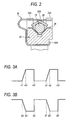
- FIG. 2 is a sectional view of the connecting portion of the connecting block 22 and the driving shaft 18.
- a first sliding member 26 and a second sliding member 28 are provided at the connecting portion of the connecting block 22 and the driving shaft 18.
- the first sliding member 26 is disposed at an upper side of the driving shaft 18, and the second sliding member 28 is disposed at a lower side of the driving shaft 18.
- the first sliding member 26 and the second sliding member 28 are members that are provided to obtain a stable frictional force between the connecting block 22 and the driving shaft 18 and are formed, for example, from stainless steel.
- the second sliding member 28 is formed to a V-shape and is fixedtotheconnectingblock22.
- the first slidingmember 26 is formed to an inverted V-shape and is positioned in a region surrounded by the four protrusions 22A of the connecting block 22.
- the first sliding member 26 is notched at its respective corner portions in accordance with the protrusions 22A of the connecting block 22.
- a pressing spring 30 is mounted onto the connecting block 22.
- the pressing spring 30 is arranged by bending a metal plate and is mounted onto the connecting block 22 by hitching a claw 30A onto a lower portion of the connecting block 22.
- the pressing spring 30 also has a pressing portion 30B that is positioned on an upper side of the first sliding member 26 and is arranged to urge the first sliding member 26 downward by the pressing portion 30B.
- the driving shaft 18 is thereby put in a state of being sandwichingly pressed by the first sliding member 26 and the second sliding member 28, and the connecting block 22 is frictionally engaged with the driving shaft 18 via the first sliding member 26 and the second sliding member 28.
- the frictional force between the connecting block 22 and the driving shaft 18 is set so that when drive pulses of a gradual voltage variation is applied to the piezoelectric element 16, the frictional force is greater than the driving force, and when drive pulses of a rapid voltage variation is applied to the piezoelectric element 16, the frictional force is less than the driving force.
- the frictional force (sliding resistance) is preferably no less than 10gf and no more than 30gf and more preferably no less than 15gf and no more than 25gf.
- aweightmember32 formedofasoftmaterial, is fixed by adhesion onto the end face 16B at the other side of the piezoelectric element 16.
- the weight member 32 prevents the end face 16B from becoming displaced more than the end face 16A.
- the weight member 32 is formed of a material with a Young's modulus less than that of each of the piezoelectric element 16 and the driving shaft 18 and, for example, is formed of a material with a Young's modulus of no more than 300MPa.
- the weight member 32 is formed of urethane rubber or urethane resin, etc., and is manufactured by mixing a powder of tungsten or other metal into the rubber or resin to make the specific gravity high.
- the specific gravity of the weight member 32 is preferably made as high as possible and is set, for example, to approximately 8 to 12.
- the face of weight member 32 at the side opposite the piezoelectric element 16 is adhered onto the mounting bracket 24.
- the mounting bracket 24 is formed by bending a thin metal plate to a square C-shape and the bent portions at both ends thereof are mounted onto the main body 14. The piezoelectric element 16 is thus supported on the main body 14 via the weight member 32 and the mounting bracket 24.
- the piezoelectric element 16 that is supported as described above is supported in a manner in which the end face 16B can be displaced along the driving direction. That is, the end face 16B of the piezoelectric element 16 can be displaced along the driving direction by the expansion or contraction of the soft weight member 32.
- FIGS. 3A and 3B show the voltages of the drive pulses shown in FIGS. 3A and 3B applied to the piezoelectric element 16.
- FIG. 3A shows the drive pulses for moving the connecting block 22 of FIG. 1 in the left direction
- FIG. 3B shows the drive pulses for moving the connecting block 22 of FIG. 1 in the right direction.
- substantially sawtooth-like drive pulses each of which rises gradually from a time ⁇ 1 to a time ⁇ 2 and drops rapidly at a time ⁇ 3, are applied to the piezoelectric element 16.
- the connecting member 20 that is affixed to the end face 16A of the piezoelectric element 16 swings and the driving shaft 18 of FIG. 1 is displaced in the left direction. Because in this process, the driving shaft 18 moves at a gradual speed, the connecting block 22 moves along with the driving shaft 18.
- the connecting block 22 of FIG. 1 can thereby be moved in the leftdirection.
- the connecting block 22 of FIG. 1 is made to repeat movement in the left direction and stoppage, and can thus be moved in the left direction.
- substantially sawtooth-like drive pulses each of which drops gradually from a time ⁇ 1 to a time ⁇ 2 and rises rapidly at a time ⁇ 3, are applied to the piezoelectric element 16.
- the connecting member 20 that is affixed to the end face 16A of the piezoelectric element 16 swings and the driving shaft 18 of FIG. 1 is displaced in the right direction. Because in this process, the driving shaft 18 is displaced at a gradual speed, the connecting block 22 moves along with the driving shaft 18.
- the connecting block 22 of FIG. 1 can thereby be moved in the right direction.
- the connecting block 22 of FIG. 1 is made to repeat movement in the right direction and stoppage, and can thus be moved in the right direction.
- FIG. 4 is a perspective view of an actuator of a comparative example.
- a piezoelectric element 16 and a driving shaft 18 are connected in series. That is, the driving shaft 18 is affixed directly onto an end face 16A of the piezoelectric element 16, and these components are positioned so that a longitudinal direction of the piezoelectric element 16 is matched with an axial direction of the driving shaft 18.
- the actuator, with which the piezoelectric element 16 and the driving shaft 18 are thus positioned in series, cannot be made short in the driving direction and becomes thin and long as a whole. A special, long, thin installation space is thus required in an equipment in which the actuator is installed and it is difficult to make the equipment compact.
- the piezoelectric element 16 and the driving shaft 18 are positioned in parallel and the actuator 10 can be made short in the driving direction. That is, it is sufficient for the length of the actuator 10 to be substantially the same as the length of the driving shaft 18 and can be made shorter than the arrangement shown in FIG. 4 by the length of the piezoelectric element 16. Because a special, long, thin installation space is thus not required in the equipment in which the actuator 10 is installed, the actuator-installed equipment can be made compact.
- a small weight member 32 is disposed between the end face 16A of the piezoelectric element 16 and the mounting bracket 24, the shape and position of the weight member are not limited thereto and, for example, a large weight member 34 may be mounted onto an outer side of the mounting bracket 24 as indicated by the alternate long and two short dashes line in FIG. 1. Even in this case, the actuator 10 can be prevented from becoming long in the driving direction. That is, whereas when the weight member 34, indicated by the alternate long and two short dashes line, is mounted onto the outer side of the mounting bracket 24 in the arrangement of the comparative example of FIG. 4, the actuator becomes large in the driving direction by the amount of the weight member 34, with the embodiment shown in FIG. 1, because the weight member is not disposed along an extension of the driving shaft 18, the actuator does not become long in the driving direction.
- the piezoelectric element 16 and the driving shaft 18 are affixed onto the same face of the connecting member 20, the present invention is not restricted thereto, and the two components may instead be affixed onto faces at opposite sides. Furthermore, the positioning of the piezoelectric element 16 and the driving shaft 18 is not restricted to a parallel positioning.
- the connecting member 20 is swingably supported with respect to the main body 14 by the engagement of the grooves 20A of the connecting member 20 with the protrusions 14A of the main body 14, the present invention is not restricted thereto, and pivotal support by a pin, etc., may be arranged. Furthermore, arrangements may be made to enable changing of the position of the swinging fulcrum (working point) along the longitudinal direction of the connecting member 20.
- the vibration of the piezoelectric element 16 can be transmitted in an amplified or attenuated manner to the driving shaft 18.
- the actuator according to the present invention applications, for example, to digital cameras, mobile phones, and other compact precision apparatuses are possible.
- driving must be performed at a low voltage of no more than 3V, and by using the actuator according to the present invention, driving at a high frequency of approximately 20kHz is enabled and the holding frame 13 can be moved at a high speed of no less than 2mm/s.
- driving at a high frequency of approximately 20kHz is enabled and the holding frame 13 can be moved at a high speed of no less than 2mm/s.
- a zoom lens requiringmovement of approximately 10mm can be moved rapidly.
- the embodiment was described above as an actuator for driving a zoom lens, the present invention is not restricted thereto and may be applied to an actuator for driving a focusing lens. Thinning in the movement direction of the lens can be accomplished in this case as well. Also, applications of the actuator according to the present invention are not restricted to applications of moving focusing lenses, zoom lenses, and other movable lenses, and use in applications in which a CCD is moved is also possible.
- the material of the weight member 32 in the present invention is not restricted to the above-described soft material and a hard material maybe used, the use of a soft material is preferable from the following points. That is, by using the weight member 32 formed of a soft material, the resonance frequency of the system arranged from the piezoelectric element 16, the driving shaft 18, the connecting member 20, and the weight member 32 is made low. By the resonance frequency being made low, effects due to scattering among arrangements of the piezoelectric element 16, the driving shaft 18, the connecting member 20, and the weight member 32 are lessened, and a stable driving force can be obtained.
- the driving frequency f can be set readily in a vibration-proof region of f ⁇ 2 1 ⁇ 2 .f 0 to lessen the effects of resonance and enable a stable driving force to be obtained. Because the driving force due to extension and contraction of the piezoelectric element 16 is thereby transmitted to the driven member reliably, the driven member can be moved accurately in the extension/contraction direction of the piezoelectric element 16. Also, because the effects due to resonance are lessened by the resonance frequency f 0 being made low, the supporting position and supporting method of the actuator can be selected arbitrarily and, for example, the actuator can be supported at a side face of the piezoelectric element 16 or a side face or an end face of driving shaft 18.
- the actuator according to the present invention because the electro-mechanical conversion element and the driving frictional member are connected via the connecting member, the need to position the electro-mechanical conversion element and the driving frictional member along a straight line is eliminated, the degree of freedom of shape is increased, and the actuator can be positioned even in a space that is small in the driving direction.
Landscapes
- Physics & Mathematics (AREA)
- General Physics & Mathematics (AREA)
- Optics & Photonics (AREA)
- General Electrical Machinery Utilizing Piezoelectricity, Electrostriction Or Magnetostriction (AREA)
- Lens Barrels (AREA)
Applications Claiming Priority (1)
| Application Number | Priority Date | Filing Date | Title |
|---|---|---|---|
| JP2005234645A JP2007049880A (ja) | 2005-08-12 | 2005-08-12 | アクチュエータ |
Publications (2)
| Publication Number | Publication Date |
|---|---|
| EP1753121A2 true EP1753121A2 (fr) | 2007-02-14 |
| EP1753121A3 EP1753121A3 (fr) | 2007-07-25 |
Family
ID=37499540
Family Applications (1)
| Application Number | Title | Priority Date | Filing Date |
|---|---|---|---|
| EP06016841A Withdrawn EP1753121A3 (fr) | 2005-08-12 | 2006-08-11 | Actionneur |
Country Status (4)
| Country | Link |
|---|---|
| US (1) | US20070035205A1 (fr) |
| EP (1) | EP1753121A3 (fr) |
| JP (1) | JP2007049880A (fr) |
| CN (1) | CN1912666B (fr) |
Cited By (1)
| Publication number | Priority date | Publication date | Assignee | Title |
|---|---|---|---|---|
| GB2445082A (en) * | 2006-12-19 | 2008-06-25 | Samsung Electro Mech | Lens driving device comprising piezoelectric actuator and guiding members |
Families Citing this family (5)
| Publication number | Priority date | Publication date | Assignee | Title |
|---|---|---|---|---|
| JP2007274746A (ja) * | 2006-03-30 | 2007-10-18 | Fujinon Corp | 駆動装置 |
| JP2009276423A (ja) * | 2008-05-13 | 2009-11-26 | Mitsumi Electric Co Ltd | 駆動装置 |
| JP5304044B2 (ja) * | 2008-06-12 | 2013-10-02 | 株式会社ニコン | 圧電アクチュエータ、レンズ鏡筒、光学機器 |
| JP5275879B2 (ja) * | 2009-04-01 | 2013-08-28 | オリンパス株式会社 | 内視鏡装置 |
| JP5523614B2 (ja) * | 2013-05-16 | 2014-06-18 | オリンパス株式会社 | 内視鏡装置 |
Citations (2)
| Publication number | Priority date | Publication date | Assignee | Title |
|---|---|---|---|---|
| JPH0469070A (ja) * | 1990-07-03 | 1992-03-04 | Canon Inc | 駆動装置 |
| JPH09205788A (ja) * | 1996-01-23 | 1997-08-05 | Minolta Co Ltd | 電気機械変換素子を使用した移動ステ−ジ |
Family Cites Families (19)
| Publication number | Priority date | Publication date | Assignee | Title |
|---|---|---|---|---|
| US3655930A (en) * | 1970-05-07 | 1972-04-11 | Powerdyne Inc | Multiple vacuum switch apparatus having longitudinal actuator |
| US4052743A (en) * | 1976-11-03 | 1977-10-04 | Arvin Industries, Inc. | Transducer carriage transport having cylindrical bearings and a grooved guide member |
| US4435666A (en) * | 1981-05-26 | 1984-03-06 | Nippon Electric Co., Ltd. | Lever actuator comprising a longitudinal-effect electroexpansive transducer and designed to prevent actuation from degrading the actuator |
| DE3706735A1 (de) * | 1986-03-03 | 1987-09-10 | Canon Kk | Vorrichtung zum einstellen des optischen systems einer kamera |
| US4886382A (en) * | 1987-02-09 | 1989-12-12 | Nec Corporation | Printing hammer comprising two hinge parts coupling an arm to a base member on both sides of a hinge coupling the arm to a piezoelectric actuator |
| JP3065716B2 (ja) * | 1991-06-19 | 2000-07-17 | オリンパス光学工業株式会社 | 圧電体駆動制御装置 |
| US5589723A (en) * | 1994-03-29 | 1996-12-31 | Minolta Co., Ltd. | Driving apparatus using transducer |
| US5656769A (en) * | 1994-08-11 | 1997-08-12 | Nikon Corporation | Scanning probe microscope |
| JP2658930B2 (ja) * | 1994-12-27 | 1997-09-30 | 日本電気株式会社 | 圧電型回転駆動装置 |
| US6114799A (en) * | 1997-02-10 | 2000-09-05 | Minolta Co., Ltd. | Driving mechanism |
| JPH1144899A (ja) * | 1997-07-25 | 1999-02-16 | Minolta Co Ltd | 電気機械変換素子を使用した駆動装置 |
| US6215605B1 (en) * | 1998-07-02 | 2001-04-10 | Minolta Co., Ltd. | Driving device |
| GB2348630B (en) * | 1998-09-09 | 2002-12-04 | Luk Lamellen & Kupplungsbau | Drive train |
| KR100526242B1 (ko) * | 2003-03-03 | 2005-11-08 | 삼성전기주식회사 | 이송장치 |
| US7045932B2 (en) * | 2003-03-04 | 2006-05-16 | Exfo Burleigh Prod Group Inc | Electromechanical translation apparatus |
| JP2004297920A (ja) * | 2003-03-27 | 2004-10-21 | Minolta Co Ltd | 駆動装置 |
| JP2005229790A (ja) * | 2004-01-13 | 2005-08-25 | Seiko Epson Corp | 駆動装置、レンズユニット、およびカメラ |
| JP2005287167A (ja) * | 2004-03-29 | 2005-10-13 | Konica Minolta Opto Inc | 駆動装置 |
| JP4032182B2 (ja) * | 2004-05-21 | 2008-01-16 | コニカミノルタホールディングス株式会社 | 圧電素子を用いたアクチュエータ |
-
2005
- 2005-08-12 JP JP2005234645A patent/JP2007049880A/ja not_active Abandoned
-
2006
- 2006-08-09 CN CN200610110782XA patent/CN1912666B/zh not_active Expired - Fee Related
- 2006-08-10 US US11/501,787 patent/US20070035205A1/en not_active Abandoned
- 2006-08-11 EP EP06016841A patent/EP1753121A3/fr not_active Withdrawn
Patent Citations (2)
| Publication number | Priority date | Publication date | Assignee | Title |
|---|---|---|---|---|
| JPH0469070A (ja) * | 1990-07-03 | 1992-03-04 | Canon Inc | 駆動装置 |
| JPH09205788A (ja) * | 1996-01-23 | 1997-08-05 | Minolta Co Ltd | 電気機械変換素子を使用した移動ステ−ジ |
Cited By (3)
| Publication number | Priority date | Publication date | Assignee | Title |
|---|---|---|---|---|
| GB2445082A (en) * | 2006-12-19 | 2008-06-25 | Samsung Electro Mech | Lens driving device comprising piezoelectric actuator and guiding members |
| GB2445082B (en) * | 2006-12-19 | 2009-07-01 | Samsung Electro Mech | Lens driving device |
| US7706089B2 (en) | 2006-12-19 | 2010-04-27 | Samsung Electro-Mechanics Co., Ltd. | Lens driving device |
Also Published As
| Publication number | Publication date |
|---|---|
| CN1912666A (zh) | 2007-02-14 |
| JP2007049880A (ja) | 2007-02-22 |
| CN1912666B (zh) | 2010-05-12 |
| EP1753121A3 (fr) | 2007-07-25 |
| US20070035205A1 (en) | 2007-02-15 |
Similar Documents
| Publication | Publication Date | Title |
|---|---|---|
| EP1753042B1 (fr) | Actionneur | |
| EP1753044A2 (fr) | Actionneur | |
| EP1720049B1 (fr) | Mécanisme d'entraînement | |
| US6836057B2 (en) | Drive mechanism employing electromechanical transducer | |
| EP1770420B1 (fr) | Actionneur | |
| EP1708287B1 (fr) | Mécanisme d'entraînement | |
| EP1788643B1 (fr) | Mécanisme d'entraînement | |
| EP1753041A2 (fr) | Actuateur | |
| EP1708353B1 (fr) | Mécanisme d'entraînement comprenant un élément de conversion d'énergie électromécanique ainsi que mécanisme photographique et téléphone cellulaire utilisant ledit mécanisme d'entraînement | |
| EP1605529A1 (fr) | Actuateur piezo-électrique | |
| EP1753121A2 (fr) | Actionneur | |
| EP1753043A2 (fr) | Actionneur | |
| US7403342B2 (en) | Lens device | |
| JP4809016B2 (ja) | アクチュエータ | |
| JP5151199B2 (ja) | 電気機械変換素子を用いた駆動装置 | |
| JP2010063345A (ja) | 駆動装置、およびこれを備えた撮像装置、電子機器 |
Legal Events
| Date | Code | Title | Description |
|---|---|---|---|
| PUAI | Public reference made under article 153(3) epc to a published international application that has entered the european phase |
Free format text: ORIGINAL CODE: 0009012 |
|
| 17P | Request for examination filed |
Effective date: 20060811 |
|
| AK | Designated contracting states |
Kind code of ref document: A2 Designated state(s): AT BE BG CH CY CZ DE DK EE ES FI FR GB GR HU IE IS IT LI LT LU LV MC NL PL PT RO SE SI SK TR |
|
| AX | Request for extension of the european patent |
Extension state: AL BA HR MK YU |
|
| PUAL | Search report despatched |
Free format text: ORIGINAL CODE: 0009013 |
|
| AK | Designated contracting states |
Kind code of ref document: A3 Designated state(s): AT BE BG CH CY CZ DE DK EE ES FI FR GB GR HU IE IS IT LI LT LU LV MC NL PL PT RO SE SI SK TR |
|
| AX | Request for extension of the european patent |
Extension state: AL BA HR MK YU |
|
| AKX | Designation fees paid |
Designated state(s): AT BE BG CH CY CZ DE DK EE ES FI FR GB GR HU IE IS IT LI LT LU LV MC NL PL PT RO SE SI SK TR |
|
| 17Q | First examination report despatched |
Effective date: 20080414 |
|
| RIC1 | Information provided on ipc code assigned before grant |
Ipc: G03B 3/10 20060101ALI20080825BHEP Ipc: G02B 7/08 20060101ALI20080825BHEP Ipc: H01L 41/09 20060101ALI20080825BHEP Ipc: H02N 2/04 20060101AFI20080825BHEP |
|
| RAP1 | Party data changed (applicant data changed or rights of an application transferred) |
Owner name: FUJIFILM CORPORATION |
|
| GRAP | Despatch of communication of intention to grant a patent |
Free format text: ORIGINAL CODE: EPIDOSNIGR1 |
|
| INTG | Intention to grant announced |
Effective date: 20130604 |
|
| STAA | Information on the status of an ep patent application or granted ep patent |
Free format text: STATUS: THE APPLICATION IS DEEMED TO BE WITHDRAWN |
|
| 18D | Application deemed to be withdrawn |
Effective date: 20131015 |