EP1980930A1 - Mobile elektronische vorrichtung - Google Patents
Mobile elektronische vorrichtung Download PDFInfo
- Publication number
- EP1980930A1 EP1980930A1 EP07707142A EP07707142A EP1980930A1 EP 1980930 A1 EP1980930 A1 EP 1980930A1 EP 07707142 A EP07707142 A EP 07707142A EP 07707142 A EP07707142 A EP 07707142A EP 1980930 A1 EP1980930 A1 EP 1980930A1
- Authority
- EP
- European Patent Office
- Prior art keywords
- housing
- magnet
- state
- display
- hall
- Prior art date
- Legal status (The legal status is an assumption and is not a legal conclusion. Google has not performed a legal analysis and makes no representation as to the accuracy of the status listed.)
- Withdrawn
Links
Images


Classifications
-
- H—ELECTRICITY
- H04—ELECTRIC COMMUNICATION TECHNIQUE
- H04M—TELEPHONIC COMMUNICATION
- H04M1/00—Substation equipment, e.g. for use by subscribers
- H04M1/02—Constructional features of telephone sets
- H04M1/0202—Portable telephone sets, e.g. cordless phones, mobile phones or bar type handsets
- H04M1/0206—Portable telephones comprising a plurality of mechanically joined movable body parts, e.g. hinged housings
- H04M1/0208—Portable telephones comprising a plurality of mechanically joined movable body parts, e.g. hinged housings characterized by the relative motions of the body parts
- H04M1/021—Portable telephones comprising a plurality of mechanically joined movable body parts, e.g. hinged housings characterized by the relative motions of the body parts using combined folding and rotation motions
- H04M1/0212—Portable telephones comprising a plurality of mechanically joined movable body parts, e.g. hinged housings characterized by the relative motions of the body parts using combined folding and rotation motions with a two degrees of freedom mechanism, i.e. folding around a first axis and rotating around a second axis perpendicular to the first
-
- G—PHYSICS
- G06—COMPUTING OR CALCULATING; COUNTING
- G06F—ELECTRIC DIGITAL DATA PROCESSING
- G06F1/00—Details not covered by groups G06F3/00 - G06F13/00 and G06F21/00
- G06F1/16—Constructional details or arrangements
- G06F1/1613—Constructional details or arrangements for portable computers
- G06F1/1615—Constructional details or arrangements for portable computers with several enclosures having relative motions, each enclosure supporting at least one I/O or computing function
- G06F1/1616—Constructional details or arrangements for portable computers with several enclosures having relative motions, each enclosure supporting at least one I/O or computing function with folding flat displays, e.g. laptop computers or notebooks having a clamshell configuration, with body parts pivoting to an open position around an axis parallel to the plane they define in closed position
- G06F1/162—Constructional details or arrangements for portable computers with several enclosures having relative motions, each enclosure supporting at least one I/O or computing function with folding flat displays, e.g. laptop computers or notebooks having a clamshell configuration, with body parts pivoting to an open position around an axis parallel to the plane they define in closed position changing, e.g. reversing, the face orientation of the screen with a two degrees of freedom mechanism, e.g. for folding into tablet PC like position or orienting towards the direction opposite to the user to show to a second user
-
- G—PHYSICS
- G06—COMPUTING OR CALCULATING; COUNTING
- G06F—ELECTRIC DIGITAL DATA PROCESSING
- G06F1/00—Details not covered by groups G06F3/00 - G06F13/00 and G06F21/00
- G06F1/16—Constructional details or arrangements
- G06F1/1613—Constructional details or arrangements for portable computers
- G06F1/1615—Constructional details or arrangements for portable computers with several enclosures having relative motions, each enclosure supporting at least one I/O or computing function
- G06F1/1622—Constructional details or arrangements for portable computers with several enclosures having relative motions, each enclosure supporting at least one I/O or computing function with enclosures rotating around an axis perpendicular to the plane they define or with ball-joint coupling, e.g. PDA with display enclosure orientation changeable between portrait and landscape by rotation with respect to a coplanar body enclosure
-
- G—PHYSICS
- G06—COMPUTING OR CALCULATING; COUNTING
- G06F—ELECTRIC DIGITAL DATA PROCESSING
- G06F1/00—Details not covered by groups G06F3/00 - G06F13/00 and G06F21/00
- G06F1/16—Constructional details or arrangements
- G06F1/1613—Constructional details or arrangements for portable computers
- G06F1/1633—Constructional details or arrangements of portable computers not specific to the type of enclosures covered by groups G06F1/1615 - G06F1/1626
- G06F1/1675—Miscellaneous details related to the relative movement between the different enclosures or enclosure parts
- G06F1/1677—Miscellaneous details related to the relative movement between the different enclosures or enclosure parts for detecting open or closed state or particular intermediate positions assumed by movable parts of the enclosure, e.g. detection of display lid position with respect to main body in a laptop, detection of opening of the cover of battery compartment
-
- H—ELECTRICITY
- H04—ELECTRIC COMMUNICATION TECHNIQUE
- H04M—TELEPHONIC COMMUNICATION
- H04M1/00—Substation equipment, e.g. for use by subscribers
- H04M1/02—Constructional features of telephone sets
- H04M1/0202—Portable telephone sets, e.g. cordless phones, mobile phones or bar type handsets
- H04M1/0206—Portable telephones comprising a plurality of mechanically joined movable body parts, e.g. hinged housings
- H04M1/0241—Portable telephones comprising a plurality of mechanically joined movable body parts, e.g. hinged housings using relative motion of the body parts to change the operational status of the telephone set, e.g. switching on/off, answering incoming call
- H04M1/0245—Portable telephones comprising a plurality of mechanically joined movable body parts, e.g. hinged housings using relative motion of the body parts to change the operational status of the telephone set, e.g. switching on/off, answering incoming call using open/close detection
Definitions
- the present invention relates to a mobile electronic apparatus, and in particular, to a mobile electronic apparatus in a folding style capable of detecting any one of four states of a first housing including a display section and a second housing including an operation section, i.e., an open state, a closed state, a reversed display state, and a 90-degree state, by using a few magnets and Hall effect ICs, and not using a rotation angle detection circuit or the like.
- mobile information terminals especially mobile phones
- mobile phones such as a strait type and a folding type are used, and especially the folding type of mobile phones are widely used and in great demand because these can be held compactly.
- the mobile phones nowadays are improved in those multiple functions, therefore they are not used only for communication, but are also used as mobile information terminals including additional functions of a browser e.g. for the internet, a sending/receiving terminal for e-mail, scheduling, and the like.
- Those contents to be displayed are varied in a wide range such as a large amount of character information, images, and the like.
- a mobile phone having a landscape display to be used when taking a picture and watching a television has been developed.
- mobile phones including a biaxial structure, a triaxial structure, or a universal hinge mechanism in which a hinge section includes both an opening/closing mechanism and a rotation mechanism have been developed, and such mobile phones which are usable while keeping the first housing having a display surface to be in a plurality of states such as being rotated with respect to the second casing, as well as being opened or closed, have been used.
- a control section is provided to detect and recognize each state in many types of mobile phones.
- a folding type mobile phone apparatus having an opening/closing function with which the upper housing is to be opened and closed in a longitudinal direction and an opening/closing function with which the same is to be opened and closed in a short side direction, with respect to the bottom housing, and in addition, a folding function with which the mobile phone is folded with the upper housing being reversed back to front (refer to Patent Document 1, for example) has been well known.
- a mobile phone 100 disclosed in Patent Document 1 enables an upper housing 103 to be opened and closed with respect to a bottom housing 101 via hinge unit 102.
- the hinge unit 102 is composed of a first hinge unit 121 having a first rotation shaft 104 and a second rotation shaft 105, and a second hinge unit 122 connected to the second rotation shaft 105 and having a third rotation shaft 106.
- FIG. 16 shows a cross-section taken along line X-X in Fig. 15 .
- a plurality of magnets 130 is attached on a surface of a flange 104a in the first rotation shaft 104.
- Approach of those magnets 130 is detected by a first rotation detecting unit 131 attached on a print substrate 113, so that a rotational angle of the first hinge unit 121 is detected.
- a plurality of magnets 132 is attached on an end face of the second rotation shaft 105, and approach of those magnets 132 is detected by a second rotation detecting unit 133 attached near the second rotation shaft 105, so that a rotational angle of the second hinge unit 122 is detected. Further, a plurality of magnets is attached on an end face of the third rotation shaft 106, and approach of those magnets is detected by a third rotation detecting unit 135 attached near the third rotation shaft 106 in the second hinge unit 122, so that a rotation angle of the third rotation shaft 106 is detected.
- each component of conventional examples is referred with reference numerals of 100s simply for convenience of explanation, but the contents are the same. However, the reference numeral for the mobile phone is 100 as it is.
- a mobile communication terminal having a structure with which a display housing is slightly turned with respect to an operation housing when the terminal is in a normally open state, or with which both housings are slightly opened when the terminal is in a reversely closed state is also known (refer to Patent Document 2, for example).
- FIG. 17 A content of Patent Document 2 is shown in Fig. 17 .
- a first housing 202 and a second housing 203 are connected openably and closably via hinge 209.
- the hinge 209 is composed of a first rotation shaft 210 and a second rotation shaft 211 orthogonal to each other.
- the first rotation shaft 210 can be rotated around an axis parallel to a plain surface of a display panel 205a, with respect to the second rotation shaft 211.
- an open/close state i.e., a state of the first housing 202 and the second housing 203 being relatively opened/closed
- an open/close detecting sensor composed of a magnet 221 and a Hall element 223
- a rotation state thereof is detected by a rotation/unrotation sensor composed of a magnet 222 and a Hall element 224.
- the magnet 221 of the open/close detecting sensor and the Hall element 224 of the rotation detecting sensor are provided in the first housing 202.
- the magnet 222 of the rotation detecting sensor is provided in the rotation shaft 210 composing the hinge 209.
- the Hall element 224 of the rotation detecting sensor is provided in the first housing 202.
- each component of the conventional example is referred with reference numerals of 200s simply for convenience of explanation, but the contents are the same.
- Patent Document 1 Japanese Patent Application Laid-open No. 2005-198062
- Patent Document 2 Japanese Patent Application Laid-open No. 2005-303688
- the first hinge unit 121 is composed of the first and the second rotation shafts 104 and 105
- the second hinge unit 122 includes the third rotation shaft 106, one end of which is connected to the second rotation shaft.
- a plurality of magnets 130 and 132 etc. is provided to each of the rotation shafts 104, 105, and 106, and respective rotation detecting units 131, 132, and 135 are provided near there. Therefore, a structure of the hinge unit 102 becomes complicated.
- the rotation shaft 104 and the like are required to be provided to the rotation shaft 104 and the like respectively, and,in addition, the rotation detecting units 131 and the like are required to be provided, a circuit construction for the rotation detecting unit 131 and the like also becomes complicated. Furthermore, three rotation shafts 104, 105, 106 and the like and the rotation detecting unit 131 and the like requires wide installation spaces, which prevents the mobile phone apparatuses from being downsized, despite the current trend for downsizing the mobile phone apparatuses.
- the magnet 222 composing the rotation detecting sensor is provided inside of the second rotation shaft 211 composing the hinge 209. Since the mobile communication terminals tend to be downsized, each component is also required to be downsized. Thus, a rotation shaft having as small a diameter as possible is to be used. Consequently, the magnet 222 is required to be installed at a precise position within the rotation shaft 211 with a small diameter, which is installation work at a position where the installment is difficult. Therefore, there are such disadvantages that the installation work becomes difficult and that productivity and conservativeness is lowered.
- the present invention proposes to solve the aforementioned problems, and an object thereof is to provide a mobile electronic apparatus capable of detecting a state of the housing in the mobile electronic apparatus from four states, i.e., an open state, a closed state where the housings are closed, a reversed display state where the housings are closed with a display reversed to face the outside, and a 90-degree state where the display is turned 90 degrees in the reversed display state, by using at least two magnetism detecting units and a few magnets, without a complicated rotation detection circuit.
- a mobile electronic apparatus includes: a first housing including a display section; and a second housing being a counterpart of the first housing and including an operation section.
- This mobile electronic apparatus includes a universal hinge section connecting the first housing and the second housing at those end sections openably and closably, and enabling the first housing to be rotated around an axis vertical to the display section of the housing and an axis parallel to the display section of the housing at the connected section.
- the mobile electronic apparatus further includes a first magnet and a second magnet fixed on a plain section in either the first housing or the second housing; and a first magnetism detecting unit and a second magnetism detecting unit for detecting magnetism of the magnets fixed on a plain section in either the first housing or the second housing so as to correspond with those magnets. Furthermore, the mobile electronic apparatus includes a state determining unit for determining an open/close state between the first and the second housings according to detection information from the first magnetism detecting unit and for determining a rotation state of the first housing according to detection information from the second magnetism detecting unit.
- the first housing and the second housing are opened and closed via the universal hinge section by using the connected end section as a rotation supporting point, and the first housing is rotated around an axis vertical to the display section of the housing and an axis parallel to the display section. Then, such an open/close state and a rotation state are determined by the state determining unit.
- the state determining unit can determine both an open/close state and a rotation state of the first housing and the second housing according to the detecting information from the first magnetism detecting unit and the second magnetism detecting unit.
- the state of housings in the mobile electronic apparatus can be determined to be any one of four states, i.e., an open state, a state where the housings are closed with a display reversed to face the outside, a reversed display state, and a 90-degree state where the display is turned 90 degrees in the reversed display state.
- the first magnet and the first magnetism detecting unit mentioned above, or the second magnet and the second magnetism detecting unit mentioned above may be disposed and fixed at positions so as to be overlapped with each other respectively when the first housing and the second housing are folded relatively.
- the closed state where the first housing and the second housing are folded can be detected more certainly.
- the magnets and the magnetism detecting units are disposed at positions so as to overlap each other, the 90-degree state where the display is turned 90 degrees in the reversed display state can be detected by setting the magnets and the magnetism detecting units at prescribed positions.
- first magnet and the first magnetism detecting unit aforementioned may be fixed at a center in each wide direction of the first and the second housings respectively, and the second magnet and the second magnetism detecting unit may be fixed in the first and the second housings respectively, which are at the positions near the universal hinge section and close to one side of the universal hinge section.
- the first magnet and the first magnetism detecting unit are only required to be provided at a center in each wide direction of the first and the second housings respectively, so that it becomes easy to confirm a position to be fixed, and attachment work is easy.
- the second magnet and the second magnetism detecting unit are provided in the first and the second housings respectively, which are at the positions near the universal hinge section and close to one side of the universal hinge section.
- the mobile electronic apparatus includes, as described, the first housing including the display section and the second housing being a counterpart of the first housing and including the operation section.
- the mobile electronic apparatus further includes the universal hinge section which connects the first housing and the second housing openably and closably, and enables the first housing to be rotated around the axis vertical to the display section of the housing and the axis parallel to the display section of the housing.
- the mobile electronic apparatus includes the first, the second, and the third magnets fixed to a plain section in either the aforementioned first or second housing, the first magnetism detecting unit fixed on a plain section in either the first or the second housing for detecting magnetism of the first magnet or the second magnet, the second magnetism detecting unit fixed on a plain section in either of the first or the second housings for detecting magnetism of the third magnet, and the state determining unit for determining an open/close state of the first and the second housings according to a detection result of the first magnetism detecting unit and determining a rotation state of the first housing according to a detection result of the second magnetism detecting unit.
- the first and the second housings are opened and closed via the universal hinge section, and the first housing is rotated around the axis vertical to the display section thereof and the axis parallel to the display section thereof. Then, such an open/close state and a rotation state are determined by the state determining unit.
- the aforementioned state determining unit can determine an open/close state and a rotation state of the first and the second housings, respectively, according to the detection information from the first magnetism detecting unit and the detection information from the second magnetism detecting unit.
- the state determining unit can detect any one of four states of the housings in the mobile electronic apparatus, i.e., an open state, a state where the housings are closed with a display reversed to face the outside, a reversed display state, and a 90-degree state where the display is turned 90 degrees in the reversed display state, without a complicated rotation detection circuit.
- either the above mentioned first or second magnet and the first magnetism detecting unit, as well as the third magnet and the second magnetism detecting unit, may be disposed and fixed at the positions so as to overlap with each other when the first housing and the second housing are folded relatively.
- the closed state where the first housing and the second housing are folded can be detected more certainly.
- the magnets and the magnetism detecting units are disposed so as to overlap each other, the 90-degree state where the display is turned 90 degrees in the reversed display state can be detected by setting the magnets and the magnetism detecting units at prescribed positions.
- first and second magnets may be set so that a south pole thereof is to be detected in the closed state, and the other may be set so that a north pole thereof is to be detected in the closed state.
- first magnet and the second magnet may be disposed on a line along a width direction of the first housing with a prescribed interval in between them so that the first magnetism detecting unit corresponds to either the first magnet or the second magnet.
- a first Hall IC detects the north pole of the first magnet in the closed state where the first housing and the second housing are folded, and the first Hall IC detects the north pole of the second magnet in the reversed display state. Consequently, the type of the pole detected by the first Hall IC is limited to only the north poles of the magnets, so that a monopolar detection Hall IC can be used for the first Hall IC. With this, costs can be effectively reduced.
- the aforementioned state determining unit is composed of a CPU into which signals detected by the first magnetism detecting unit and the second magnetism detecting unit are inputted. Then, the CPU may include a determining function which functions when prescribed detection signals are inputted from the first magnetism detecting unit and the second magnetism detecting unit, for determining which combination information corresponds to the inputted detection signals, from the combination information generated in advance for indicating the combination of output signals from the first detecting unit and the second detecting unit and states relevant to the output signals.
- combinations of the first and the second housing states and relevant signals outputted from the first and the second magnetism detecting units are stored so as to be corresponded in advance. Therefore, the state determining unit can easily determine a state of housings according to received signals.
- the first housing and the second housing are connected at each end section openably and closably, and the first housing is rotated around the axis vertical to the display section thereof and the axis parallel to the display section thereof at those end sections. Further, an open/close state and a rotation state are determined by the state determining unit.
- an unconventional and excellent mobile electronic apparatus capable of detecting any one of four states of the housings in the mobile electronic apparatus, i.e., the open state, the state where the housings are closed with the display reversed to face the outside, a reversed display state, and the 90-degree state where the display is turned 90 degrees in the reversed display state, quickly and certainly in real time by using a few units, that is, by using two magnetism detecting units and a few magnets, and not using a complicated rotation detecting unit, can be offered.
- a mobile electronic apparatus 10 includes a display housing 11 that is the first housing, and an operation housing 21 that is the second housing being a counterpart of the display housing 11 for inputting information.
- the display housing 11 is formed in the shape of a thin casing, and one of its main faces (i.e. a front face) includes a display surface 11A that is a display section having a main display. Further, the other one of its main faces which is an opposite face of the one of its main faces (i.e. a back surface) includes a sub-display (an illustration is omitted) which has a smaller display screen than the main display.
- the operation housing 21 is formed in nearly the same shape as the display housing 11, and one of its main faces (i.e. a front face) includes an operation panel 21A having each of operational keys for inputting information. Further, the other one of its main faces which is an opposite face to the one of its main faces (i.e. a back surface) includes for example a digital camera composed of an imaging element, and a side face of the operation housing 21 includes a side key (an illustration is omitted) to perform a shutter operation when taking a picture with the digital camera.
- the above-mentioned display housing 11 and the operation housing 21 are connected at each end section via a universal hinge 30 openably and closably (that is, foldably) toward a direction of an arrow A. Further, the display housing 11 can be rotated around an axis B vertical to the display surface 11A of the display housing 11 and around an axis C parallel to the display surface 11A, according to the universal hinge 30.
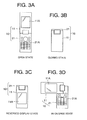
- the display housing 11 and the operation housing 21 can be in any one of four states, i.e., an open state in which both housings 11 and 21 are open as shown in Fig. 3A , a closed state in which the display surface 11A and the operation panel 21A face inside so as to be folded and housed as shown in Fig. 3B , a reversed display state in which the display surface 11A and the operation panel 21A are reversed to be opened as shown in Fig. 3C , and a 90-degree state in which the display surface 11A and the operation panel 21A are in the reversed display state and turned 90 degrees as shown in Fig. 3D .
- the display housing 11 includes two magnets, i.e. a first magnet 12 and a second magnet 13, and the operation housing 21 includes a first Hall IC 22 that is the first magnetism detecting unit, and a second Hall IC 23 that is the second magnetism detecting unit.
- the first magnet 12 is disposed at the center in the width direction of the display housing 11, which is at an end section of the display housing 11 and at the opposite side to the position of the universal hinge 30 having the display surface 11A in between them, and fixed on, for example, an unillustrated substrate inside the display housing 11.
- the second magnet 13 is disposed at a side end section in the width direction of the display housing 11 (on the left side in Fig. 1 ) and in between the display surface 11A and the universal hinge 30, and fixed on, for example the unillustrated substrate inside the display housing 11. Accordingly, the first magnet 12 and the second magnet 13 are provided on a plain section of the display housing 11. In this case, the second magnet 13 may be disposed on the opposite side of the aforementioned position, that is on the right side in Fig. 1 .
- the first magnet 12 and the second magnet 13 are formed with, for example, magnet pieces in a thin rectangular solid shape, generating a magnetic field toward a direction vertical to the main face. That is, one of the main faces in each magnet 12, 13, for example surfaces contacting with the substrate are the north poles of the magnetic poles, and the other of the main faces, that is, convex upper end surfaces are the south poles. Then, a magnetic field line passing through each magnet 12, 13 is vertical to both main faces.
- the first Hall IC 22 is disposed at the center in the width direction of the operation housing 21, positioned at the opposite side to the first magnet 12 such that the first Hall IC 22 and the first magnet 12 are arranged symmetrically,with the universal hinge 30 centered in between them, and fixed on, for example, an unillustrated substrate inside the operation housing 21. Therefore, when the display housing 11 is folded, the first Hall IC 22 overlaps the first magnet 12 provided in the display housing 11 in a plain direction of the display housing 11 and the operation housing 21, so that the first Hall IC 22 and the first magnet 12 correspond to each other.
- the second Hall IC 23 is disposed at one side end section in the width direction in between the operation panel 21A of the operation housing 21 and the universal hinge 30, and being positioned at the opposite side to the second magnet 13 of the display housing 11 such that second Hall IC 23 and the second magnet 13 are arranged symmetrically with the universsal hinge 30 centered in between them, and fixed on, for example, an unillustrated substrate inside the operation housing 21.
- the first Hall IC 22 and the second Hall IC 23 are provided in a plain section of the operation housing 21.
- an IC chip with three terminals composed of for example a Hall element. an operation amplifier, and a comparator is used.
- density of magnetic flux is low, a detection signal with a level of a voltage being high (high-level) is generated.
- a detection signal with a level of a voltage being low is generated.
- Magnetism of the first magnet 12, as described, is detected by the first Hall IC 22, so that open/close movement of the display housing 11 and the operation housing 21 is detected. Further, magnetism of the second magnet 13 is detected by the second Hall IC 23 so that rotation movement of the display housing 11 with respect to the operation housing 21 is detected.
- the first magnet 12 and the second magnet 13 are positioned in opposite directions with respect to the first Hall IC 22 and the second Hall IC 23, having the universal hinge 30 in between them. Accordingly, each Hall IC 22 and 23 cannot detect the magnetism of each magnet 12 and 13, which are outside detection ranges.
- the first Hall IC 22 is set so as to output a detection signal in a high level 41
- the second Hall IC 23 is set so as to output a detection signal in a high level 43.
- Operations to be performed in the open state are: a calling operation by an off-hook key, a receiving operation when an incoming call has arrived, a shooting operation by a digital camera, an editing operation for an E-mail, a browsing operation for an incoming E-mail, a searching operation for an electronic telephone book, a browsing operation for a website when the internet is accessed, and the like. Further, when making a call or receiving a call, inputted destination number, originator number, or the like are displayed on the main display. Moreover, when taking a picture, an image to be photographed is displayed on the main display as a finder.
- the first Hall IC 22 is set so as to output a detection signal in a low level 42
- the second Hall IC 23 is set so as to output a detection signal in a low level 44.
- the housings are in the reversed display state, as shown in Fig. 3C .
- the reversed display state as shown in Fig. 5 in an enlarged view
- the first magnet 12 and the first Hall IC 22 overlap each other in the plain direction of the display housing 11 and the operation housing 21. Accordingly, the magnetism of the first magnet 12 is within the magnetic detection range of the first Hall IC 22. In such a state, the first Hall IC 22 is set so as to output a detection signal in the low level 42.
- the second magnet 13 and the second Hall IC 23 are apart from each other by a prescribed dimension in the width direction of the display housing 11 and the like,while the display housing 11 and the operation housing 21 overlap each other. Accordingly, the second magnet 13 is outside the magnetic detection range of the second Hall IC 23. In such a state, the second Hall IC 23 is set so as to output a detection signal in the high level 43.
- Operations to be performed in the reversed display state are: a calling operation with the side key, a receiving operation when a call is arrived, a call, a photographing operation, a browsing operation when an E-mail arrives, a browsing operation for downloaded information from a website and the like.
- a calling operation with the side key a receiving operation when a call is arrived, a call, a photographing operation, a browsing operation when an E-mail arrives, a browsing operation for downloaded information from a website and the like.
- a state becomes the 90-degree state, as shown in Fig. 3D .
- the display housing 11 and the operation housing 21 partially overlap each other while the first magnet 12 and the first Hall IC 22 are apart from each other by a prescribed dimension in a 90-degree direction. Accordingly, the first magnet 12 is outside the magnetic detection range of the first Hall IC 22. In such a state, the first Hall IC 22 outputs a detection signal in the high level 41, as well as the case in Fig. 3A .
- the display housing 11 and the operation housing 21 partially overlap each other in the plain direction. Accordingly, the second magnet 13 is within the magnetic detection range of the second Hall IC 23. In such a state, the second Hall IC 23 is set so as to output a detection signal in the low level 44.
- the display housing 11 and the operation housing 21 can be held in any one of the four states such as the open state and the like, and in each state, the first Hall IC 22 and the second Hall IC 23 detect different main faces of the first and the second magnets 12 and 13, namely detect different magnetic poles, respectively.
- the first Hall IC 22 and the second Hall IC 23 face each south pole of the first magnet 12 and the second magnet 13, and detect those south poles, respectively.
- the back surface of the display housing 11 faces the operation surface 21A of the operation housing 21, so that the first Hall IC 22 faces the north pole of the first magnet 12 and detects that north pole.
- the back surface of the display housing 11 faces the operation surface 21A of the operation housing 21.
- the second Hall IC 23 faces the north pole of the second magnet 13 and detects that north pole.
- bipolar type Hall ICs capable of detecting both south and north poles are used.
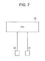
- Outputs from the first Hall IC 22 and the second Hall IC 23 as described are inputted into a CPU 35 that is the state determining unit, as shown in Fig. 7 .
- the CPU 35 recognizes each state shown in Figs. 3A - 3D according to combinations, as shown in Fig. 8 , of detection signals outputted from the first Hall IC 22 and the second Hall IC 23. Further, the CPU 35 is housed in the operation housing 21, for example, and fixed. Here, such combinations of detection signals and the four states are set in advance.
- the CPU 35 can recognize the open state according to the combinations in Fig. 8 . That is, the state is shown in Figs. 1 and 3A .
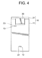
- the CPU 35 can recognize the closed state according to the combinations in Fig. 8 . That is, the state is shown in Figs. 3B and 4 .
- the CPU 35 can recognize the reversed display state according to the combinations in Fig. 8 . That is, the state is shown in Figs. 3C and 5 .
- the CPU 35 can recognize the 90-degree state according to the combinations in Fig. 8 . That is, the state is shown in Figs. 3D and 6 . As described above, each state is recognized by the CPU 35, and,accordingly, operational control is suitably performed in response to each state.
- the CPU 35 receives a detection signal in the high level 41 from the first Hall IC 22 and a detection signal in the high level 43 from the second Hall IC 23 respectively. Then, the CPU 35 recognizes it as being in the open state according to the previously set combinations of detection signals and each state, and performs a prescribed process.
- the CPU 35 receives detection signals in the low level 42 from the first Hall IC 22 and in the low level 44 from the second Hall IC respectively. Then, the CPU 35 recognizes it as being in the closed state according to the previously set combinations of detection signals and each state, and performs a prescribed process.
- the CPU 35 receives detection signals in the low level 42 from the first Hall IC 22 and in the high level 43 from the second Hall IC 23,respectively. Then, the CPU 35 recognizes it as being in the reversed display state according to the previously set combinations of detection signals and each state, and performs a prescribed process.
- the CPU 35 receives detection signals in the high level 41 from the first Hall IC 22 and in the low level 44 from the second Hall IC 23, respectively. Then, the CPU 35 recognizes it as being in the 90-degree state according to the previously set combinations of output signals and each state, and performs a prescribed process.
- the first exemplary embodiment is constructed and functions as described above, and therefore following effects can be obtained.
- FIG. 9 - 14 a second exemplary embodiment of the present invention will be explained with reference to Figs. 9 - 14 .
- the same construction members as in the mobile electronic apparatus 10 of the first exemplary embodiment have the same numbers as in the first exemplary embodiment.
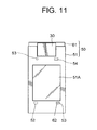
- a mobile electronic apparatus 50 shown in Figs. 9 - 14 is different from the first exemplary embodiment described above in that a display housing 51 of the first housing is provided with three magnets. Other constructions are almost the same as in the first exemplary embodiment.
- the mobile electronic apparatus 50 can be used effectively in a case where a magnet cannot be fixed at the center in the width direction of the display housing 11, or failure occurs when one of the Hall ICs is a bipolar Hall IC.
- the mobile electronic apparatus 50 includes: the display housing 51, an operation housing 52 that is the second housing.
- the display housing 51 includes three magnets, i.e., a first magnet 52, a second magnet 53, and a third magnet 54.
- the first magnet 52 and the second magnet 53 are provided at an end section, opposite side to the universal hinge 30, of the display housing 51, and on the outside of the display surface 51A, having a prescribed interval in between them on a line along the width direction of the display housing 51.
- the first magnet 52 and the second magnet 53 are apart from the universal hinge 30 by almost the same interval as in the case of the first magnet 12 in the first exemplary embodiment.
- the third magnet 54 is provided at nearly the same position with the second magnet 13 in the first exemplary embodiment described above, and, the third magnet 54 and the second magnet 53 are disposed on almost the same line along a longitudinal direction of the display housing 51.
- a convex upper surface of the first magnet 52 is set to be a north pole
- a convex upper surface of the second magnet 53 is set to be a south pole.
- the operation housing 61 includes two Hall ICs, i.e., a first Hall IC 62 as the first magnetism detecting unit, and a second Hall IC 63 as the second magnetism detecting unit.
- the first Hall IC 62 is provided at a position which is shifted from the center toward one side end in the width direction of the operation housing 61 so as to correspond to the first magnet 52 in the display housing 51.
- the second Hall IC 63 is disposed at almost the same position with the second Hall IC 23 in the first exemplary embodiment described above so as to correspond to the third magnet 54 in the display housing 51.
- each magnet 52, 53, 54, and the first and the second Hall ICs 62, 63 may be disposed at those positions the other way around.
- the first Hall IC 62 detects magnetism of the first magnet 52, so that open/close movement of the display housing 51 and the operation housing 61 is detected. Further, the second Hall IC 63 detects magnetism of the third magnet 54, so that rotation movement of the display housing 51 with respect to the operation housing 61 is detected.
- the first magnet 52, the second magnet 53, and the third magnet 54 are provided at the positions which are in the opposite direction with respect to the first Hall IC 62 and the second Hall IC 63, having the universal hinge 30 in between them. Therefore, each Hall IC 42 and 43 cannot detect each magnet 12, 13, and 14 because those are out of detection ranges.
- the first Hall IC 62 is set so as to output a detection signal in a high level 45
- the second Hall IC 63 is set so as to output a signal in the high level 43.
- the first Hall IC 62 is set so as to output a detection signal in a low level 46
- the second Hall IC 63 is set so as to output a detection signal in the low level 44.
- the second magnet 53 and the first Hall IC 62 overlap each other in the plain direction of the display housing 51 and the operation housing 61. Accordingly, the second magnet 53 is in the magnetic detection range of the first Hall IC 62. In such a state, the first Hall IC 62 is set so as to output a detection signal in the low level 46.
- the display housing 51 and the operation housing 61 partially contact each other, while respective magnets 52 and 54 are apart from the second Hall IC 63. Therefore, the second Hall IC 63 cannot detect the magnetism of the first magnet 52 and the third magnet 54 which are outside the magnetic detection range. In such a state, the second Hall IC 63 is set to output a detection signal in the high level 43.
- the display housing 51 and the operation housing 61 partially overlap each other in the plain direction, however, the first magnet 52 and the second magnet 53 are apart from the first Hall IC 62 by a prescribed dimension in the 90-degree direction. Therefore, the first Hall IC 62 cannot detect the magnetism of the first magnet 52 and the second magnet 53 which are outside the magnetic detection range. In such a state, the first Hall IC 62 is set so as to output a detection signal in the high level 45.
- the display housing 51 and the operation housing 61 partially overlap each other in the plain direction, so that the second Hall IC 63 can detect the magnetism of the third magnet 54 which is in the detection range. In such a state, the second Hall IC 63 is set so as to output a signal in the low level 44.
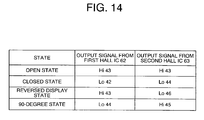
- the outputted detection signals from the first Hall IC 62 and the second Hall IC 63, described above, are inputted into a CPU 65 that is the determining unit, as shown in Fig. 13 . Then, the CPU 65 recognizes the four states shown in Figs. 9 - 12 according to combinations of detection signals from the first Hall IC 62 and the second Hall IC 63, as shown in Fig. 14 .
- the CPU 65 recognizes the open state according to the combinations in Fig. 14 , that is, the state shown in Fig. 9 .
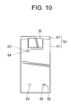
- the CPU 65 recognizes the closed state according to the combinations in Fig. 14 , that is, the state shown in Fig. 10 .
- the CPU 65 recognizes the reversed display state according to the combinations in Fig. 14 , that is, the state shown in Fig. 11 .
- the CPU 65 When a detection signal in the low level 44 from the first Hall IC 62 and a detection signal in the high level 45 from the second Hall IC 63 are inputted into the CPU 65, the CPU 65 recognizes the 90-degree state according to the combinations in Fig. 14 , that is, the state shown in Fig. 12 . Accordingly, the CPU 65 recognizes each state, and operational control is performed suitably in response to each state.
- the first magnet 52 is set such that the north pole thereof is to be detected in the closed state
- the second magnet 53 is set such that the south pole thereof is to be detected in the closed state
- the state of the display housing 51 and the operation housing 61 is changed into four states, therefore poles to be detected are also changed. That is, in the closed state shown in Fig. 10 , the first Hall IC 62 detects the north pole of the first magnet 52. Meanwhile, in the state where the housings are closed with the display reversed to face the outside shown in Fig. 11 , because the first Hall IC 62 faces the north pole which is on the opposite side of the south pole of the second magnet 53, that north pole is detected. Consequently, the first Hall IC 62 detects only the north poles, so that a monopolar detection Hall IC can be used for the first Hall IC 62.
- the CPU 65 receives a detection signal in the high level 43 from the first Hall IC 62 and a detection signal in the high level 45 from the second Hall IC 63,respectively. Then, the CPU 65 recognizes it as being in the open state according to the previously set combinations of detection signals and each state, and performs a prescribed process.
- the CPU 65 receives detection signals in the low level 42 from the first Hall IC 62 and in the low level 44 from the second Hall IC 63, respectively. Then, the CPU 65 recognizes it as being in the open state according to the previously set combinations of detection signals and each state, and performs a prescribed process.
- the CPU 65 receives a detection signal in the low level 42 from the first Hall IC 62 and a detection signal in the high level 43 from the second Hall IC 63,respectively. Then, the CPU 65 recognizes it as being in the open state according to the previously set combinations of detection signals and each state, and performs a prescribed process.
- the CPU 65 receives a signal in the high level 41 from the first Hall IC 62 and a signal in the low level 44 from the second Hall IC 63, respectively. Then, the CPU 65 recognizes it as being in the open state according to the previously set combinations of output signals and each state, and performs a prescribed process.
- the display housing 51 and the operation housing 61 are opened and closed via the universal hinge 30, and,in addition, the display housing 51 is rotated around the axis B and the axis C, and then such an open/close state and a rotation state can be distinguished by the CPU 65.
- the CPU 65 can distinguish the open/close state and the rotation state of the display housing 51 and the operation housing 61 respectively according to a detection result of the first Hall IC 62 and a detection result of the second Hall IC 63.
- any one of the four states of the mobile electronic apparatus 50 i.e., the open state, the closed state where the housings are closed, the reversed display state where the housings are closed with the display reversed to face the outside, and the 90-degree state where the display is turned 90 degrees in the reversed display state, can be detected without using a complicated rotation detection circuit.
- the first magnet 52 is set such that the north pole thereof is to be detected in the closed state
- the second magnet 53 is set such that the south pole thereof is to be detected in the closed state
- the first Hall IC 62 detects the north pole of the first magnet 52 in the closed state.
- the first Hall IC 62 faces the north pole which is on the opposite side to the south pole of the second magnet 53, so that the first Hall IC 62 detects that north pole. Consequently, the type of the pole detected by the first Hall IC 62 is limited to only the north poles of the magnets, and a monopolar detection Hall IC can be used for the first Hall IC 62. Thus, costs can be reduced compared to a case using the bipolar detection Hall IC.
- the present invention is not limited to the aforementioned exemplary embodiments.
- the present invention includes any transformation and any modification that can achieve an object of the present invention.
- the display housing 11 includes the first magnet 12 and the second magnet 13, and the operation housing 12 includes the first Hall IC 22 and the second Hall IC 23.
- the present invention is not limited to this.
- the display housing 11 may include the first Hall IC 22 and the second Hall IC 23, and the operation housing 12 may include the first magnet 12 and the second magnet 13.
- the second magnet 13 and the second Hall IC 23 may be disposed at a symmetric position on the opposite side in the width direction of the display housing 11 and the operation housing 12.
- the display housing 51 includes the first magnet 52, the second magnet 53, and the third magnet 54
- the operation housing 62 includes the first Hall IC 62 and the second Hall IC 63.
- the display housing 51 may include the first Hall IC 62 and the second Hall IC 63
- the operation housing 62 may include the first magnet 52, the second magnet 53, and the third magnet 54.
- the first magnet 52, the second magnet 53, the third magnet 54, and the first Hall IC 62, the second Hall IC 63 may be disposed the other way around with respect to the above arrangement.
- the present invention is usable for mobile phones and portable game consoles.
Landscapes
- Engineering & Computer Science (AREA)
- Theoretical Computer Science (AREA)
- Computer Hardware Design (AREA)
- Physics & Mathematics (AREA)
- Human Computer Interaction (AREA)
- General Engineering & Computer Science (AREA)
- General Physics & Mathematics (AREA)
- Signal Processing (AREA)
- Mathematical Physics (AREA)
- Telephone Set Structure (AREA)
- Telephone Function (AREA)
Applications Claiming Priority (2)
| Application Number | Priority Date | Filing Date | Title |
|---|---|---|---|
| JP2006021529A JP4102834B2 (ja) | 2006-01-30 | 2006-01-30 | 携帯電子機器 |
| PCT/JP2007/050879 WO2007086333A1 (ja) | 2006-01-30 | 2007-01-22 | 携帯電子機器 |
Publications (2)
| Publication Number | Publication Date |
|---|---|
| EP1980930A1 true EP1980930A1 (de) | 2008-10-15 |
| EP1980930A4 EP1980930A4 (de) | 2012-03-14 |
Family
ID=38309126
Family Applications (1)
| Application Number | Title | Priority Date | Filing Date |
|---|---|---|---|
| EP07707142A Withdrawn EP1980930A4 (de) | 2006-01-30 | 2007-01-22 | Mobile elektronische vorrichtung |
Country Status (5)
| Country | Link |
|---|---|
| US (1) | US8688178B2 (de) |
| EP (1) | EP1980930A4 (de) |
| JP (1) | JP4102834B2 (de) |
| CN (1) | CN101375227A (de) |
| WO (1) | WO2007086333A1 (de) |
Cited By (2)
| Publication number | Priority date | Publication date | Assignee | Title |
|---|---|---|---|---|
| EP2339819A4 (de) * | 2008-10-20 | 2013-01-02 | Nec Corp | Vorrichtung und verfahren zur statuserkennung in einer mobilvorrichtung |
| EP4386491A4 (de) * | 2021-08-25 | 2024-12-18 | Huawei Technologies Co., Ltd. | Verfahren zur reduzierung des stromverbrauchs einer wearable-vorrichtung und wearable-vorrichtung |
Families Citing this family (22)
| Publication number | Priority date | Publication date | Assignee | Title |
|---|---|---|---|---|
| JP5176300B2 (ja) * | 2006-09-22 | 2013-04-03 | 富士通株式会社 | 電子機器、その制御方法及びその制御プログラム |
| US8355761B2 (en) | 2007-12-20 | 2013-01-15 | Nec Corporation | Folding/sliding mobile terminal with separate antennas in two separate casings |
| US7953462B2 (en) * | 2008-08-04 | 2011-05-31 | Vartanian Harry | Apparatus and method for providing an adaptively responsive flexible display device |
| KR101602368B1 (ko) * | 2009-07-06 | 2016-03-21 | 엘지전자 주식회사 | 이동 단말기 |
| US20100331059A1 (en) * | 2009-06-30 | 2010-12-30 | Jeffrey Apgar | Apparatus with swivel hinge and associated method |
| BRPI1106263A2 (pt) * | 2010-08-19 | 2013-01-22 | Canon Kk | dispositivo eletrânico |
| JP5665415B2 (ja) * | 2010-08-19 | 2015-02-04 | キヤノン株式会社 | 電子機器 |
| KR101951473B1 (ko) * | 2012-10-15 | 2019-02-22 | 엘지전자 주식회사 | 이동 단말기 |
| JP5975173B2 (ja) * | 2013-04-30 | 2016-08-23 | 富士通株式会社 | 分割筐体の結合装置及び分割筐体を備えた電子装置 |
| CN103475782B (zh) * | 2013-09-13 | 2015-09-30 | 广东欧珀移动通信有限公司 | 提供快捷控制功能的方法及移动终端 |
| KR101929590B1 (ko) * | 2013-12-05 | 2019-03-13 | 매그나칩 반도체 유한회사 | 3차원 구조로 배치된 복수의 홀 센서를 이용한 센싱 시스템 및 이를 이용한 장치 |
| WO2015199714A1 (en) * | 2014-06-27 | 2015-12-30 | Hewlett-Packard Development Company, L.P. | Computing device with a rotatable display member |
| JP2016138950A (ja) * | 2015-01-27 | 2016-08-04 | キヤノン株式会社 | 電子機器 |
| US9918534B2 (en) * | 2016-03-29 | 2018-03-20 | Microsoft Technology Licensing, Llc | Cover for an electronic device |
| JP2018072429A (ja) * | 2016-10-25 | 2018-05-10 | キヤノン株式会社 | 電子機器および撮像装置 |
| US10754393B2 (en) * | 2017-11-17 | 2020-08-25 | Microsoft Technology Licensing, Llc | Multi-panel computing device having integrated magnetic coupling structure(s) |
| EP3565224B1 (de) * | 2018-05-04 | 2020-07-15 | Guangdong Oppo Mobile Telecommunications Corp., Ltd. | Mobiles endgerät |
| CN209105239U (zh) * | 2019-01-21 | 2019-07-12 | Oppo广东移动通信有限公司 | 可折叠壳体组件及可折叠电子设备 |
| CN111694265A (zh) * | 2019-03-13 | 2020-09-22 | 奇酷互联网络科技(深圳)有限公司 | 智能手表 |
| US10990608B2 (en) * | 2019-03-19 | 2021-04-27 | Snowflake Inc. | Transferring connections in a multiple deployment database |
| EP4296822B1 (de) | 2021-05-06 | 2026-02-04 | Samsung Electronics Co., Ltd. | Elektronische vorrichtung mit scharnierstruktur |
| JP7444841B2 (ja) * | 2021-11-22 | 2024-03-06 | Necパーソナルコンピュータ株式会社 | 携帯型情報処理装置 |
Family Cites Families (16)
| Publication number | Priority date | Publication date | Assignee | Title |
|---|---|---|---|---|
| JP2776783B2 (ja) | 1995-12-19 | 1998-07-16 | 埼玉日本電気株式会社 | 移動状態検出回路 |
| JP2003174495A (ja) | 2001-09-28 | 2003-06-20 | Nec Corp | 折り畳み式携帯情報端末 |
| JP2003298698A (ja) * | 2002-03-29 | 2003-10-17 | Nec Corp | 折り畳み式携帯情報端末 |
| EP1594295A4 (de) * | 2003-02-12 | 2009-05-06 | Panasonic Corp | Tragbare endgeräteeinrichtung |
| US20040198439A1 (en) * | 2003-04-01 | 2004-10-07 | Dong-Ryong Kim | Device and method for displaying pictures in a mobile terminal |
| JP2005078316A (ja) * | 2003-08-29 | 2005-03-24 | Kyocera Corp | 携帯端末装置 |
| JP3994959B2 (ja) | 2003-11-14 | 2007-10-24 | カシオ計算機株式会社 | 携帯型電子機器、および、携帯型電話機 |
| JP2005159391A (ja) | 2003-11-20 | 2005-06-16 | Matsushita Electric Ind Co Ltd | 開閉式携帯端末装置 |
| JP2005198062A (ja) | 2004-01-08 | 2005-07-21 | Matsushita Electric Ind Co Ltd | 折り畳み式携帯電話装置 |
| JP4151847B2 (ja) | 2004-04-01 | 2008-09-17 | シャープ株式会社 | 携帯通信端末及びレシーバー動作制御方法 |
| JP4350582B2 (ja) | 2004-04-13 | 2009-10-21 | シャープ株式会社 | 携帯情報端末 |
| JP2005354384A (ja) | 2004-06-10 | 2005-12-22 | Nec Saitama Ltd | 折り畳み型携帯端末機器の開閉検出機構及び開閉検出方法 |
| US20060135226A1 (en) * | 2004-12-21 | 2006-06-22 | Samsung Electronics Co., Ltd. | Mobile communication terminal for changing operation mode based on opening direction of folder cover and method thereof |
| JP2006191438A (ja) | 2005-01-07 | 2006-07-20 | Matsushita Electric Ind Co Ltd | 携帯端末 |
| JP2006211394A (ja) * | 2005-01-28 | 2006-08-10 | Toshiba Corp | 折り畳み型携帯端末装置 |
| US20070242887A1 (en) | 2005-03-15 | 2007-10-18 | Sharp Kabushiki Kaisha | Portable Terminal, Image Information Matching Method for Portable Terminal, Image Information Matching Program, and Recording Medium |
-
2006
- 2006-01-30 JP JP2006021529A patent/JP4102834B2/ja not_active Expired - Lifetime
-
2007
- 2007-01-22 US US12/161,186 patent/US8688178B2/en active Active
- 2007-01-22 WO PCT/JP2007/050879 patent/WO2007086333A1/ja not_active Ceased
- 2007-01-22 EP EP07707142A patent/EP1980930A4/de not_active Withdrawn
- 2007-01-22 CN CNA2007800038914A patent/CN101375227A/zh active Pending
Cited By (2)
| Publication number | Priority date | Publication date | Assignee | Title |
|---|---|---|---|---|
| EP2339819A4 (de) * | 2008-10-20 | 2013-01-02 | Nec Corp | Vorrichtung und verfahren zur statuserkennung in einer mobilvorrichtung |
| EP4386491A4 (de) * | 2021-08-25 | 2024-12-18 | Huawei Technologies Co., Ltd. | Verfahren zur reduzierung des stromverbrauchs einer wearable-vorrichtung und wearable-vorrichtung |
Also Published As
| Publication number | Publication date |
|---|---|
| EP1980930A4 (de) | 2012-03-14 |
| WO2007086333A1 (ja) | 2007-08-02 |
| JP2007208335A (ja) | 2007-08-16 |
| US20100234073A1 (en) | 2010-09-16 |
| US8688178B2 (en) | 2014-04-01 |
| CN101375227A (zh) | 2009-02-25 |
| JP4102834B2 (ja) | 2008-06-18 |
Similar Documents
| Publication | Publication Date | Title |
|---|---|---|
| US8688178B2 (en) | Mobile electronic apparatus | |
| US7269443B2 (en) | Mobile communication unit with camera lens opening means in closed folder | |
| KR100792920B1 (ko) | 절첩식 휴대 단말 | |
| CN100499677C (zh) | 移动终端 | |
| US7526325B2 (en) | Triple-axis rotation folder-type portable apparatus | |
| JP4697256B2 (ja) | 表示装置 | |
| KR100646618B1 (ko) | 휴대 단말 장치 | |
| KR100677300B1 (ko) | 휴대용 단말기 | |
| JP4350582B2 (ja) | 携帯情報端末 | |
| WO2005122537A1 (ja) | 電子機器、および、筐体の向き検出方法 | |
| KR100526555B1 (ko) | 휴대용 무선 단말기 | |
| US7659829B2 (en) | Method of improving the detection of opening and closing of a slide-type mobile communication terminal and an apparatus thereof | |
| JP5028585B2 (ja) | 電子機器 | |
| JP2008294490A (ja) | 折り畳み式電子機器、および折り畳み式電子機器の筐体位置検出方法 | |
| JP2006038777A (ja) | 携帯情報端末機 | |
| KR20030003056A (ko) | 휴대형 단말기 | |
| JP4515211B2 (ja) | 電子機器 | |
| KR20060124084A (ko) | 폴더형 단말기의 디스플레이 모드 자동 전환하는 방법 및장치 | |
| JP4456826B2 (ja) | 重ね型携帯端末装置 | |
| KR20060065299A (ko) | 폴더의 회전에 따라 화면 디스플레이 모드를 제어하는이동 통신 단말기 | |
| JP2005333219A (ja) | 携帯型情報表示装置 | |
| KR100575750B1 (ko) | 보조 멀티기능키를 구비한 휴대용 단말기 | |
| KR20050027469A (ko) | 폴더형 이동통신 단말기 | |
| JP5041372B2 (ja) | 端末装置、及び外部装置 | |
| KR20040038022A (ko) | 회전형 카메라가 장착된 휴대폰 |
Legal Events
| Date | Code | Title | Description |
|---|---|---|---|
| PUAI | Public reference made under article 153(3) epc to a published international application that has entered the european phase |
Free format text: ORIGINAL CODE: 0009012 |
|
| 17P | Request for examination filed |
Effective date: 20080730 |
|
| AK | Designated contracting states |
Kind code of ref document: A1 Designated state(s): DE FR GB IT |
|
| DAX | Request for extension of the european patent (deleted) | ||
| RBV | Designated contracting states (corrected) |
Designated state(s): DE FR GB IT |
|
| A4 | Supplementary search report drawn up and despatched |
Effective date: 20120213 |
|
| RIC1 | Information provided on ipc code assigned before grant |
Ipc: G06F 1/16 20060101AFI20120207BHEP Ipc: H04M 1/02 20060101ALI20120207BHEP |
|
| 17Q | First examination report despatched |
Effective date: 20140828 |
|
| RAP1 | Party data changed (applicant data changed or rights of an application transferred) |
Owner name: LENOVO INNOVATIONS LIMITED (HONG KONG) |
|
| STAA | Information on the status of an ep patent application or granted ep patent |
Free format text: STATUS: THE APPLICATION IS DEEMED TO BE WITHDRAWN |
|
| 18D | Application deemed to be withdrawn |
Effective date: 20150602 |