EP1980905B1 - Image capturing apparatus comprising a lens protection barrier - Google Patents
Image capturing apparatus comprising a lens protection barrier Download PDFInfo
- Publication number
- EP1980905B1 EP1980905B1 EP08154376A EP08154376A EP1980905B1 EP 1980905 B1 EP1980905 B1 EP 1980905B1 EP 08154376 A EP08154376 A EP 08154376A EP 08154376 A EP08154376 A EP 08154376A EP 1980905 B1 EP1980905 B1 EP 1980905B1
- Authority
- EP
- European Patent Office
- Prior art keywords
- lens
- barrier
- unit
- imaging apparatus
- video camera
- Prior art date
- Legal status (The legal status is an assumption and is not a legal conclusion. Google has not performed a legal analysis and makes no representation as to the accuracy of the status listed.)
- Ceased
Links
Images


Classifications
-
- G—PHYSICS
- G03—PHOTOGRAPHY; CINEMATOGRAPHY; ANALOGOUS TECHNIQUES USING WAVES OTHER THAN OPTICAL WAVES; ELECTROGRAPHY; HOLOGRAPHY
- G03B—APPARATUS OR ARRANGEMENTS FOR TAKING PHOTOGRAPHS OR FOR PROJECTING OR VIEWING THEM; APPARATUS OR ARRANGEMENTS EMPLOYING ANALOGOUS TECHNIQUES USING WAVES OTHER THAN OPTICAL WAVES; ACCESSORIES THEREFOR
- G03B11/00—Filters or other obturators specially adapted for photographic purposes
- G03B11/04—Hoods or caps for eliminating unwanted light from lenses, viewfinders or focusing aids
- G03B11/043—Protective lens closures or lens caps built into cameras
-
- H—ELECTRICITY
- H04—ELECTRIC COMMUNICATION TECHNIQUE
- H04N—PICTORIAL COMMUNICATION, e.g. TELEVISION
- H04N23/00—Cameras or camera modules comprising electronic image sensors; Control thereof
- H04N23/50—Constructional details
- H04N23/55—Optical parts specially adapted for electronic image sensors; Mounting thereof
-
- G—PHYSICS
- G03—PHOTOGRAPHY; CINEMATOGRAPHY; ANALOGOUS TECHNIQUES USING WAVES OTHER THAN OPTICAL WAVES; ELECTROGRAPHY; HOLOGRAPHY
- G03B—APPARATUS OR ARRANGEMENTS FOR TAKING PHOTOGRAPHS OR FOR PROJECTING OR VIEWING THEM; APPARATUS OR ARRANGEMENTS EMPLOYING ANALOGOUS TECHNIQUES USING WAVES OTHER THAN OPTICAL WAVES; ACCESSORIES THEREFOR
- G03B17/00—Details of cameras or camera bodies; Accessories therefor
- G03B17/56—Accessories
Definitions
- the present invention relates to an imaging apparatus including a photographic lens protection means.
- lens cap type protection means are used for protecting the photographic lens.
- Conventional lens cap type protection means attach a lens cap having an attachment structure to a filter screw thread on the object side of a front lens element of the photographic lens. Since the lens cap is detached when capturing an image, it has been proposed to link the lens cap to the grip belt of the imaging apparatus by a cord or the like to prevent the lens cap from being lost (Japanese Patent Application Laid-Open No. 11-271839 ).
- a structure has been commercially developed which provides a cover for the lens cap protection unit, a so-called "lens barrier", that when an image is not being captured is positioned on the object side of a front lens element of the photographic lens to protect the photographic lens, and when an image is being captured retracts from the object side of a front lens element of the photographic lens .
- the lens barrier there are a type where the user of the imaging apparatus moves the cover manually, and a type where the cover is moved electrically using a motor.
- Lens barrier covers are typically one of two types: a rotating type which opens and shuts by rotating a plurality of blade members like a diaphragm; or a sliding type which operates by making about one or two plate-shaped members slide across.
- sliding type lens barriers two types are representative: barriers which are exposed to the front face of the device body and which form an exterior part (see Japanese Patent Application Laid-Open No. 2004-173100 ); and lens barriers built into the body which are arranged inside the exterior part of the device body and are only exposed to the outside at the photographic lens opening (see U.S. Patent Application Publication No. 2005/0094027 ). Since the latter type does not need to take up a large surface area on the exterior of the device front face, in recent years this type is used in many digital video cameras and digital still cameras.
- a plate-shaped member has to be stored in the body.
- a space for housing the plate-shaped member of the lens barrier has to be provided inside the imaging apparatus.
- the plate-shaped member of the lens barrier needs to be arranged on the object side of the front lens element of the photographic lens.
- the flash unit and the microphone have been arranged at a position which avoids the operating range of the plate-shaped member of the lens barrier.
- the microphone is arranged on the upper face of the device to avoid the lens barrier built into the body and to avoid the front face which is used for holding the device by hand.
- the microphone faces out from the upper face rather than from the object side, and thus this structure has the drawback that sound from the object side cannot be efficiently collected. Arranging the microphone on the face of the object side while avoiding the lens barrier built into the body inevitably leads to an increase in the surface area of the object side of the imaging apparatus body.
- Fig. 8 illustrates an external perspective view of a video camera mounted with a conventional lens barrier built into the camera body.
- Figs. 9A and 9B illustrate a frontal view and a mid-section cross sectional view of a state where the lens is protected by a lens barrier.
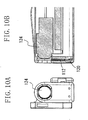
- Figs. 10A and 10B illustrate a frontal view and a mid-section cross sectional view of a lens exposed state.
- the lens barrier 112 can be made to slide up and down by manually moving the barrier knob 114 up and down.
- the lens barrier 112 protects the photographic lens 124 when an image is not being captured, and exposes the photographic lens 124 to the object side when an image is captured.
- the lens barrier 112 is retracted into the lens barrier retraction space 120 illustrated in Fig. 9B .
- the microphone 122 for collecting the sounds of an object is arranged on a lower side of the lens barrier retraction space 120.
- the front face of the video camera 110 specifically, the external surface area when viewed from the object face side, needs to be equal to or greater than the sum of the surface area of the lens barrier 112, the surface area of the lens barrier retraction space 120, and the surface area of the microphone 122.
- the microphone 122 when the microphone 122 is arranged on a lower side of the lens barrier retraction space 120, the height 118 of the video camera lens barrel portion increases.
- the height of the lens barrel portion is not often viewed as a problem.
- the present invention is directed to an imaging apparatus which is smaller yet does not have an inferior exterior design.
- the present invention in its first aspect provides an imaging apparatus as specified in claim 1.
- the present invention in its second aspect provides an imaging apparatus as specified in claims 2 to 3.
- the surface area of the object face side of the device body can be reduced.
- the size of the device itself can be made smaller, thereby improving portability and the degree of freedom in exterior design.
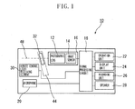
- Fig. 1 is a block diagram illustrating the structure of a digital video camera according to the exemplary embodiments of the present invention.
- Fig. 2 is an external perspective view of the digital video camera.
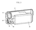
- Fig. 3 is a perspective view of the internal mechanisms of the digital video camera.
- Fig. 4 is an external perspective view shown from the rear face of the digital video camera.
- Figs. 5A and 5B are respectively a frontal view and a mid-section cross sectional view of the digital video camera in a lens protected state.
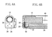
- Figs. 6A and 6B are respectively a frontal view and a mid-section cross sectional view of the digital video camera in a lens exposed state.
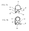
- Figs. 7A and 7B are views illustrating the positional relationship between the lens barrier and the photographic lens as seen from the front face.
- Fig. 8 is an external perspective view of a conventional digital video camera
- Figs. 9A and 9B are respectively a frontal view and a mid-section cross sectional view of a conventional video camera in a lens protected state.
- Figs. 10A and 10B are respectively a frontal view and a mid-section cross sectional view of a conventional video camera in a lens exposed state.
- Fig. 1 illustrates the structure of a digital video camera 10 according to exemplary embodiments of the present invention.
- the digital video camera 10 can record and playback video and audio of an object. First, the video and audio recording operation will be described.
- the photographic lens 12 forms an optical image of the object on an image sensor 14.
- An opening for exposing the photographic lens 12 is provided on a casing which serves as an exterior part of the camera 10.
- the image sensor 14 is configured from, for example, charge coupled device (CCD) image sensors or complementary metal-oxide semiconductor (CMOS) image sensors.
- CMOS complementary metal-oxide semiconductor
- the image sensor 14 converts optical images of the object to an electrical video signal.
- the photographic lens 12 and the image sensor 14 form a camera unit 16.
- a signal processing circuit 18 converts the video signal from the image sensor 14 into a predetermined format, and feeds the converted signal to a display unit 24 and a recording unit 26.
- the display unit 24 is formed from a liquid crystal display (LCD) or an organic electroluminescence (EL) display device.
- the display unit 24 displays the video signal from the signal processing circuit 18.
- the recording unit 26 records the video signal from the signal processing circuit 18 in a not-shown recording medium.
- the recording medium may be, for example, a magnetic tape, an optical disk, a magnetic disk, a semiconductor memory or the like.
- a microphone (monochrome microphone or a stereo microphone unit) 20 captures audio of the object for conversion to an electrical signal.
- the signal processing circuit 18 converts the audio signal from the microphone 20 into a predetermined format. If audio output is required, the signal processing circuit 18 feeds the audio signal to a speaker 28. For recording, the signal processing circuit 18 feeds the audio signal to recording unit 26.
- the recording unit 26 records the audio signal from the signal processing circuit 18 together with the above-described video signal in the recording medium.
- the video and audio playback operation will now be described.
- the video and audio recorded in the recording unit 26 are played back and fed to the signal processing circuit 18.
- the signal processing circuit 18 feeds the playback video signal from the recording unit 26 to the display unit 24, and the playback audio signal from the recording unit 26 to the speaker 28.
- the playback video is displayed on the screen of the display unit 24, and the playback audio is output from the speaker 28.
- an operation unit 22 a user instructs the digital video camera 10 to carry out this series of recording and playback operations.
- the operation unit 22 is configured from a switch, a dial, a touch panel, a potentiometer or the like.
- a control signal can be sent from a remote control device by infrared rays to a remote control light receiving element 30 to operate the digital video camera 10.
- a transmission unit using means other than infrared rays may also be employed.
- Fig. 2 illustrates an external perspective view of the digital video camera 10 in a lens protected state in which the photographic lens 12 is protected by a lens barrier 32.
- Fig. 3 illustrates the internal mechanisms of the digital video camera 10 in a lens exposed state in which the photographic lens 12 is exposed to the object side.
- the lens barrier 32 shields the opening exposing the photographic lens 12 to the object side, and in a lens exposed state, the lens barrier 32 retracts to a position which does not shield this opening.
- Fig. 4 illustrates an external perspective view looking down from the rear face side of the digital video camera 10.
- the lens barrier 32 is integrally formed with a barrier knob 36.
- a user of the digital video camera 10 moves the lens barrier 32 between a position shielding or protecting the photographic lens 12 (lens protecting position) and a position exposing the photographic lens 12 (lens exposing position).
- the lens barrier 32 is formed, for example, by an opaque plastic plate or a metal plate.
- the barrier knob 36 is revealed on the right side face of the digital video camera 10.
- a system in which the user moves the lens barrier 32 by moving the barrier knob 36 up and down by hand is a so-called manual lens barrier.
- the display unit 24 is arranged on the right side face of the digital video camera 10, and is movably configured with respect to the digital video camera 10 by a hinge or the like.
- a microphone opening 34 is arranged on the front face of the digital video camera 10.
- the microphone 20 is arranged inside the microphone opening 34. Sound entering from the microphone opening 34 is input into the microphone 20.
- a remote control light receiving window 38 is arranged on the front face of the digital video camera 10.
- the remote control light receiving element 30 is arranged on an inner side of the remote control light receiving window 38.
- the operation unit 22 is arranged at the rear face of the digital video camera 10. As described above, the operation unit 22 is configured from a switch, a dial, a touch panel, a volume control or the like.
- Fig. 5A illustrates a frontal view of the digital video camera 10 in a lens protected state
- Fig. 5B illustrates a mid-section cross sectional view corresponding to Fig. 5A
- Fig. 6A illustrates a frontal view of the digital video camera 10 in a lens exposed state
- Fig. 6B illustrates a mid-section cross sectional view corresponding to Fig. 6A .
- the lens barrier 32 protects the front lens element of the photographic lens 12 by being located on the object side of the photographic lens 12.
- the lens barrier 32 is slideably moveable along a track inclined at a prescribed oblique angle 42 with respect to the optical axis 48 of the photographic lens 12.
- the prescribed angle is also inclined obliquely with respect to the plane perpendicular to the optical axis 48.
- This inclined angle 42 is determined by the respective sizes of the digital video camera 10, the photographic lens 12, and the microphone 20.
- the angle 42 is about 82 degrees (or 98 degrees) to the optical axis, although the present invention is not limited to this angle.
- the size of the device in the direction orthogonal to the optical axis direction of the device body can be made smaller than that when the direction is perpendicular to the optical axis 48 direction.
- a lens barrier retraction space 44 that is, a position (lens exposing position) into which the lens barrier 32 retracts for exposing the photographic lens 12, is provided on a lower side of the photographic lens 12. Further, the microphone 20 and the remote control light receiving element 30 are arranged on the object side of the lens barrier retraction space 44. The microphone 20 and the remote control light receiving element 30 are connected to a circuit board 46 by wiring 50. Compared with a conventional structure, wherein the microphone is arranged under the lens barrier retraction space, the total height 40 of the digital video camera 10 can be made smaller.
- an imaging apparatus comprises: a photographic lens (12, 124); a photographic lens protection unit (32, 112) which moves between a lens protecting position for protecting the photographic lens (12, 124) and a lens exposing position for exposing the photographic lens (12, 124) in a state ready for capturing an image; and an electrical component arranged on a body object side, wherein the photographic lens protection unit (32, 112) reaches the lens exposing position by moving to a rear face side of the electrical component.
- the lens barrier 32 when the lens barrier 32 is retracted into the lens barrier retraction space 44, the photographic lens 12 is exposed to the object side. In this exposed state, the digital video camera 10 is in a state ready for image capture. Since the lens barrier 32 is located behind the rear face of the microphone 20, the lens barrier 32 has the effect of preventing the drive noises of the photographic lens 12 and the recording unit 26 of the digital video camera 10 from entering into the microphone 20, or at least attenuating the noises.
- Figs. 7A and 7B illustrate the positional relationship between the lens barrier 32 and the microphone 20 as seen from the front face.
- the lens barrier 32 is at a lens protecting position
- Fig. 7B the lens barrier 32 is at a lens exposing position.
- a notch 52 is provided in a lower corner of the lens barrier 32.
- This notch 52 serves as a path for the wiring 50 to pass through when the lens barrier 32 is at the lens exposing position, specifically, when retracted to the rear face side of the microphone 20 and the remote control light receiving element 30.
- the wiring 50 passes through the notch 52 and connects with the circuit board 46. If the notch 52 is not located on the lens barrier 32, the wiring 50 has to be passed through a position which avoids the lens barrier retraction space 44, whereby the total height and object side surface area of the digital video camera 10 body increase. While in this exemplary embodiment the wiring 50 was used as a signal line, a medium other than the wiring 50, such as a flexible circuit board or an optical fiber, may also be used.
- the lens barrier By configuring the lens barrier in the above-described manner, the surface area of the object face side of the device body can be reduced while mounting the lens barrier 32 on the digital video camera 10 as a photographic lens protection unit. As a result, the size of the device itself can be made smaller, thereby improving portability and the degree of freedom in exterior design.
- the photographic lens protection unit according to the present invention is not limited to this embodiment.
- the slide direction of the lens barrier 32 was inclined with respect to the optical axis 48 of the photographic lens 12 and with respect to the plane perpendicular to the optical axis.
- the lens barrier 32 may also be moved between a lens protecting position close to the object and a lens exposing position further away from the object by rotating the lens barrier 32.
- the lens barrier 32 itself is formed by an opaque plastic plate or a metal plate, the lens barrier may also be a transparent or light transmissive plate, or a colored plate, or a member having other optical properties.
- the microphone 20 and the remote control light receiving element 30 were arranged on the object side of the lens barrier retraction space 44.
- electrical components other than the microphone 20 and the remote control light receiving element 30 can be arranged on the object side of the lens barrier retraction space 44.
- Examples of such electrical components include a speaker as a sound generating unit, a range sensor for autofocus as a light receiving unit, a flash light generating member or a light emitting diode (LED) as a light generating unit, an infrared communication unit or a wireless local area network (LAN) module as a transmission/reception unit, a connector or a jack as an input/output unit, a barrier drive motor or a solenoid as a drive unit, a circuit board, a flexible circuit board as a signal line, a power coil, a flash capacitor, a resistance and the like.
- a speaker as a sound generating unit
- a range sensor for autofocus as a light receiving unit
- a flash light generating member or a light emitting diode (LED) as a light generating unit
- LED light emitting diode
- LAN wireless local area network
- barrier drive motor or a solenoid as a drive unit
- a circuit board a flexible circuit board as a signal
- the present invention can be applied to digital still cameras, mobile phones, personal digital assistants and the like, so long as the imaging apparatus has a photographic lens.
- the movement system of the lens barrier 32 is not limited to the configuration of the above-described exemplary embodiment.
- a so-called electric lens barrier which uses a motor or a solenoid may also be employed.
Landscapes
- Physics & Mathematics (AREA)
- General Physics & Mathematics (AREA)
- Engineering & Computer Science (AREA)
- Multimedia (AREA)
- Signal Processing (AREA)
- Studio Devices (AREA)
- Blocking Light For Cameras (AREA)
- Camera Bodies And Camera Details Or Accessories (AREA)
- Structure And Mechanism Of Cameras (AREA)
Applications Claiming Priority (1)
| Application Number | Priority Date | Filing Date | Title |
|---|---|---|---|
| JP2007105441A JP5084334B2 (ja) | 2007-04-13 | 2007-04-13 | 撮像装置 |
Publications (2)
| Publication Number | Publication Date |
|---|---|
| EP1980905A1 EP1980905A1 (en) | 2008-10-15 |
| EP1980905B1 true EP1980905B1 (en) | 2011-09-21 |
Family
ID=39559142
Family Applications (1)
| Application Number | Title | Priority Date | Filing Date |
|---|---|---|---|
| EP08154376A Ceased EP1980905B1 (en) | 2007-04-13 | 2008-04-11 | Image capturing apparatus comprising a lens protection barrier |
Country Status (5)
| Country | Link |
|---|---|
| US (1) | US8016496B2 (enExample) |
| EP (1) | EP1980905B1 (enExample) |
| JP (1) | JP5084334B2 (enExample) |
| KR (1) | KR100977444B1 (enExample) |
| CN (1) | CN101285987A (enExample) |
Families Citing this family (3)
| Publication number | Priority date | Publication date | Assignee | Title |
|---|---|---|---|---|
| JP5896729B2 (ja) * | 2011-12-27 | 2016-03-30 | キヤノン株式会社 | レンズバリアユニット及び撮像装置 |
| CN103246127B (zh) * | 2013-04-15 | 2016-08-10 | 华为技术有限公司 | 遮挡盖滑动结构及具有该遮挡盖滑动结构的视讯设备 |
| CN114530050B (zh) * | 2022-02-21 | 2023-02-24 | 游天悦 | 一种公交车实景调度方法及调度辅助系统 |
Family Cites Families (34)
| Publication number | Priority date | Publication date | Assignee | Title |
|---|---|---|---|---|
| JPS56106230A (en) * | 1980-01-30 | 1981-08-24 | Nitto Kogaku Kk | Optical system cover device of camera |
| JPS58154924U (ja) * | 1982-04-10 | 1983-10-17 | 株式会社リコー | カメラの保護カバ−装置 |
| JPS62143935U (enExample) | 1986-02-06 | 1987-09-10 | ||
| TW275669B (enExample) * | 1994-09-21 | 1996-05-11 | Haking Ind Mechanics & Optiks | |
| JP3395552B2 (ja) * | 1996-12-06 | 2003-04-14 | 株式会社ニコン | レンズカバーを有するカメラ |
| US5740480A (en) * | 1997-02-20 | 1998-04-14 | Eastman Kodak Company | Camera with movable first lens cover which supports movable second lens cover which opens during movement of first lens cover |
| JPH1141498A (ja) * | 1997-07-16 | 1999-02-12 | Pikuseru Giken Kk | 電子カメラ |
| JPH1164929A (ja) | 1997-08-22 | 1999-03-05 | Sega Enterp Ltd | 光学機器のレンズ遮蔽装置 |
| EP1024396B1 (en) * | 1997-10-06 | 2004-05-26 | Fuji Photo Film Co., Ltd. | Lens-carrying film unit having protective cover |
| JPH11218801A (ja) * | 1998-01-29 | 1999-08-10 | Olympus Optical Co Ltd | レンズ保護カバー付きカメラ |
| JPH11258657A (ja) | 1998-03-10 | 1999-09-24 | Fuji Photo Film Co Ltd | カメラ |
| JPH11271839A (ja) | 1998-03-19 | 1999-10-08 | Matsushita Electric Ind Co Ltd | レンズキャップ取付け装置 |
| JP2000147600A (ja) * | 1998-11-16 | 2000-05-26 | Konica Corp | カバー駆動装置及びデジタルスチルカメラ |
| JP4042140B2 (ja) * | 1999-01-29 | 2008-02-06 | 富士フイルム株式会社 | バリア機構 |
| JP3123544B2 (ja) * | 1999-05-07 | 2001-01-15 | 敏機 山田 | 発光体付きスチルカメラ |
| JP2001109045A (ja) * | 1999-10-06 | 2001-04-20 | Olympus Optical Co Ltd | カメラ |
| JP4474035B2 (ja) | 2000-10-03 | 2010-06-02 | 富士フイルム株式会社 | 撮像装置 |
| JP2002287213A (ja) | 2001-03-26 | 2002-10-03 | Asahi Optical Co Ltd | レンズバリヤ機構 |
| JP4139942B2 (ja) * | 2002-02-01 | 2008-08-27 | 富士フイルム株式会社 | 発光体付きカメラ |
| JP3793471B2 (ja) * | 2002-03-01 | 2006-07-05 | ペンタックス株式会社 | カメラ |
| US6735381B2 (en) * | 2002-10-04 | 2004-05-11 | Eastman Kodak Company | Camera panel assembly having one-piece lens cover/slider |
| JP2004173100A (ja) | 2002-11-21 | 2004-06-17 | Canon Inc | 撮像装置 |
| JP4223828B2 (ja) * | 2003-02-20 | 2009-02-12 | 富士フイルム株式会社 | 撮像装置 |
| US20040263666A1 (en) | 2003-04-21 | 2004-12-30 | Kiyoaki Tsuji | Lens barrier mechanism and image pickup apparatus |
| JP2004341223A (ja) | 2003-05-15 | 2004-12-02 | Nikon Corp | カメラ |
| JP2005077574A (ja) * | 2003-08-29 | 2005-03-24 | Sony Corp | 撮像装置 |
| CN2667526Y (zh) | 2003-12-11 | 2004-12-29 | 梁坚平 | 具有移动多媒体信息传输装置的人体感应数码照相机 |
| JP2005208122A (ja) | 2004-01-20 | 2005-08-04 | Olympus Corp | 光学機器の外装材 |
| US7092624B2 (en) * | 2004-05-17 | 2006-08-15 | Jerry W. Perry | Camera with cold neon display areas |
| JP2006047588A (ja) | 2004-08-03 | 2006-02-16 | Olympus Corp | 撮像装置 |
| JP4486460B2 (ja) * | 2004-09-24 | 2010-06-23 | 日本電産コパル株式会社 | カメラ用レンズ鏡胴 |
| JP2006171604A (ja) | 2004-12-20 | 2006-06-29 | Canon Inc | 撮像装置 |
| US20060224427A1 (en) | 2005-03-30 | 2006-10-05 | International Business Machines Corporation | Method, system, and program product for individual and group work space allocation and utilization |
| US20090034958A1 (en) * | 2007-07-30 | 2009-02-05 | Karl Allen Dierenbach | Gaze Attracting System for Image Capturing |
-
2007
- 2007-04-13 JP JP2007105441A patent/JP5084334B2/ja not_active Expired - Fee Related
-
2008
- 2008-04-02 US US12/061,427 patent/US8016496B2/en not_active Expired - Fee Related
- 2008-04-03 KR KR1020080031043A patent/KR100977444B1/ko not_active Expired - Fee Related
- 2008-04-11 EP EP08154376A patent/EP1980905B1/en not_active Ceased
- 2008-04-11 CN CNA2008100899500A patent/CN101285987A/zh active Pending
Also Published As
| Publication number | Publication date |
|---|---|
| JP5084334B2 (ja) | 2012-11-28 |
| US20080253759A1 (en) | 2008-10-16 |
| JP2008262072A (ja) | 2008-10-30 |
| US8016496B2 (en) | 2011-09-13 |
| EP1980905A1 (en) | 2008-10-15 |
| KR20080092849A (ko) | 2008-10-16 |
| CN101285987A (zh) | 2008-10-15 |
| KR100977444B1 (ko) | 2010-08-24 |
Similar Documents
| Publication | Publication Date | Title |
|---|---|---|
| JP5000428B2 (ja) | 撮像装置 | |
| JP4302548B2 (ja) | カメラ及び電子機器 | |
| JP5128245B2 (ja) | 撮像装置 | |
| CN103188429B (zh) | 摄像设备 | |
| EP1980905B1 (en) | Image capturing apparatus comprising a lens protection barrier | |
| US20060114348A1 (en) | Digital camera and lens barrel unit for digital camera | |
| CN110278361B (zh) | 移动终端 | |
| US20040233303A1 (en) | Electronic camera | |
| US20060217148A1 (en) | Camera phone with large sensor | |
| US20120154674A1 (en) | Image-pickup apparatus | |
| JP6157253B2 (ja) | 光学装置および撮像装置 | |
| JP6141132B2 (ja) | 撮像装置 | |
| JP6223031B2 (ja) | 撮像装置 | |
| KR101626000B1 (ko) | 개선된 필터 구조를 갖춘 디지털 카메라 | |
| JP2012141425A (ja) | 表示装置 | |
| JPWO2006035580A1 (ja) | レンズ鏡胴、および該レンズ鏡胴を備えた撮像装置、カメラ、携帯機器 | |
| JP2013130797A (ja) | 電子機器 | |
| JP2006284841A (ja) | 固体撮像装置 | |
| JP2008193228A (ja) | 撮像装置 | |
| KR101025402B1 (ko) | 촬상 장치, 캠 장치 및 광학 줌 기구 | |
| JP2007114421A (ja) | レンズユニット及びカメラシステム | |
| CN120856971A (zh) | 马达、摄像模组及电子设备 | |
| JP2005077787A (ja) | レンズ装置 | |
| JP5147978B2 (ja) | 撮像装置 | |
| KR20090030096A (ko) | 편리한 셀프 촬영 기능을 구비하는 디지털 카메라 |
Legal Events
| Date | Code | Title | Description |
|---|---|---|---|
| PUAI | Public reference made under article 153(3) epc to a published international application that has entered the european phase |
Free format text: ORIGINAL CODE: 0009012 |
|
| AK | Designated contracting states |
Kind code of ref document: A1 Designated state(s): AT BE BG CH CY CZ DE DK EE ES FI FR GB GR HR HU IE IS IT LI LT LU LV MC MT NL NO PL PT RO SE SI SK TR |
|
| AX | Request for extension of the european patent |
Extension state: AL BA MK RS |
|
| 17P | Request for examination filed |
Effective date: 20090415 |
|
| AKX | Designation fees paid |
Designated state(s): DE FR GB |
|
| 17Q | First examination report despatched |
Effective date: 20101008 |
|
| GRAP | Despatch of communication of intention to grant a patent |
Free format text: ORIGINAL CODE: EPIDOSNIGR1 |
|
| GRAS | Grant fee paid |
Free format text: ORIGINAL CODE: EPIDOSNIGR3 |
|
| GRAA | (expected) grant |
Free format text: ORIGINAL CODE: 0009210 |
|
| AK | Designated contracting states |
Kind code of ref document: B1 Designated state(s): DE FR GB |
|
| REG | Reference to a national code |
Ref country code: GB Ref legal event code: FG4D |
|
| REG | Reference to a national code |
Ref country code: DE Ref legal event code: R096 Ref document number: 602008009936 Country of ref document: DE Effective date: 20111117 |
|
| PLBE | No opposition filed within time limit |
Free format text: ORIGINAL CODE: 0009261 |
|
| STAA | Information on the status of an ep patent application or granted ep patent |
Free format text: STATUS: NO OPPOSITION FILED WITHIN TIME LIMIT |
|
| 26N | No opposition filed |
Effective date: 20120622 |
|
| REG | Reference to a national code |
Ref country code: DE Ref legal event code: R097 Ref document number: 602008009936 Country of ref document: DE Effective date: 20120622 |
|
| REG | Reference to a national code |
Ref country code: FR Ref legal event code: PLFP Year of fee payment: 9 |
|
| REG | Reference to a national code |
Ref country code: FR Ref legal event code: PLFP Year of fee payment: 10 |
|
| PGFP | Annual fee paid to national office [announced via postgrant information from national office to epo] |
Ref country code: GB Payment date: 20170420 Year of fee payment: 10 Ref country code: DE Payment date: 20170430 Year of fee payment: 10 Ref country code: FR Payment date: 20170425 Year of fee payment: 10 |
|
| REG | Reference to a national code |
Ref country code: DE Ref legal event code: R119 Ref document number: 602008009936 Country of ref document: DE |
|
| GBPC | Gb: european patent ceased through non-payment of renewal fee |
Effective date: 20180411 |
|
| PG25 | Lapsed in a contracting state [announced via postgrant information from national office to epo] |
Ref country code: DE Free format text: LAPSE BECAUSE OF NON-PAYMENT OF DUE FEES Effective date: 20181101 |
|
| PG25 | Lapsed in a contracting state [announced via postgrant information from national office to epo] |
Ref country code: GB Free format text: LAPSE BECAUSE OF NON-PAYMENT OF DUE FEES Effective date: 20180411 |
|
| PG25 | Lapsed in a contracting state [announced via postgrant information from national office to epo] |
Ref country code: FR Free format text: LAPSE BECAUSE OF NON-PAYMENT OF DUE FEES Effective date: 20180430 |