EP1976037B1 - Electromechanical conversion element, vibration actuator, vibration actuator driving device, lens barrel and camera - Google Patents
Electromechanical conversion element, vibration actuator, vibration actuator driving device, lens barrel and camera Download PDFInfo
- Publication number
- EP1976037B1 EP1976037B1 EP20080006045 EP08006045A EP1976037B1 EP 1976037 B1 EP1976037 B1 EP 1976037B1 EP 20080006045 EP20080006045 EP 20080006045 EP 08006045 A EP08006045 A EP 08006045A EP 1976037 B1 EP1976037 B1 EP 1976037B1
- Authority
- EP
- European Patent Office
- Prior art keywords
- conversion element
- vibration actuator
- electrodes
- electromechanical conversion
- driving
- Prior art date
- Legal status (The legal status is an assumption and is not a legal conclusion. Google has not performed a legal analysis and makes no representation as to the accuracy of the status listed.)
- Not-in-force
Links
- 238000006243 chemical reaction Methods 0.000 title claims description 36
- 230000010287 polarization Effects 0.000 claims description 13
- 238000001514 detection method Methods 0.000 claims description 12
- 230000033001 locomotion Effects 0.000 claims description 5
- 230000002093 peripheral effect Effects 0.000 description 11
- 230000007274 generation of a signal involved in cell-cell signaling Effects 0.000 description 10
- 239000000853 adhesive Substances 0.000 description 5
- 230000001070 adhesive effect Effects 0.000 description 5
- 230000004048 modification Effects 0.000 description 5
- 238000012986 modification Methods 0.000 description 5
- 230000000750 progressive effect Effects 0.000 description 5
- 238000010586 diagram Methods 0.000 description 4
- 229920001971 elastomer Polymers 0.000 description 4
- 238000000034 method Methods 0.000 description 3
- 239000003990 capacitor Substances 0.000 description 2
- 239000004020 conductor Substances 0.000 description 2
- 230000007613 environmental effect Effects 0.000 description 2
- 238000004381 surface treatment Methods 0.000 description 2
- 239000012790 adhesive layer Substances 0.000 description 1
- 230000002411 adverse Effects 0.000 description 1
- 229910052782 aluminium Inorganic materials 0.000 description 1
- XAGFODPZIPBFFR-UHFFFAOYSA-N aluminium Chemical compound [Al] XAGFODPZIPBFFR-UHFFFAOYSA-N 0.000 description 1
- 238000005452 bending Methods 0.000 description 1
- 230000005540 biological transmission Effects 0.000 description 1
- 229920005549 butyl rubber Polymers 0.000 description 1
- 230000006866 deterioration Effects 0.000 description 1
- 230000000694 effects Effects 0.000 description 1
- 230000005284 excitation Effects 0.000 description 1
- 239000000284 extract Substances 0.000 description 1
- 230000005669 field effect Effects 0.000 description 1
- 238000010304 firing Methods 0.000 description 1
- 238000005259 measurement Methods 0.000 description 1
- 229910052751 metal Inorganic materials 0.000 description 1
- 239000002184 metal Substances 0.000 description 1
- 239000007769 metal material Substances 0.000 description 1
- 230000007935 neutral effect Effects 0.000 description 1
- 230000003287 optical effect Effects 0.000 description 1
Images


Classifications
-
- H—ELECTRICITY
- H02—GENERATION; CONVERSION OR DISTRIBUTION OF ELECTRIC POWER
- H02N—ELECTRIC MACHINES NOT OTHERWISE PROVIDED FOR
- H02N2/00—Electric machines in general using piezoelectric effect, electrostriction or magnetostriction
-
- H—ELECTRICITY
- H02—GENERATION; CONVERSION OR DISTRIBUTION OF ELECTRIC POWER
- H02N—ELECTRIC MACHINES NOT OTHERWISE PROVIDED FOR
- H02N2/00—Electric machines in general using piezoelectric effect, electrostriction or magnetostriction
- H02N2/10—Electric machines in general using piezoelectric effect, electrostriction or magnetostriction producing rotary motion, e.g. rotary motors
- H02N2/14—Drive circuits; Control arrangements or methods
-
- G—PHYSICS
- G02—OPTICS
- G02B—OPTICAL ELEMENTS, SYSTEMS OR APPARATUS
- G02B7/00—Mountings, adjusting means, or light-tight connections, for optical elements
- G02B7/02—Mountings, adjusting means, or light-tight connections, for optical elements for lenses
- G02B7/04—Mountings, adjusting means, or light-tight connections, for optical elements for lenses with mechanism for focusing or varying magnification
- G02B7/08—Mountings, adjusting means, or light-tight connections, for optical elements for lenses with mechanism for focusing or varying magnification adapted to co-operate with a remote control mechanism
-
- G—PHYSICS
- G03—PHOTOGRAPHY; CINEMATOGRAPHY; ANALOGOUS TECHNIQUES USING WAVES OTHER THAN OPTICAL WAVES; ELECTROGRAPHY; HOLOGRAPHY
- G03B—APPARATUS OR ARRANGEMENTS FOR TAKING PHOTOGRAPHS OR FOR PROJECTING OR VIEWING THEM; APPARATUS OR ARRANGEMENTS EMPLOYING ANALOGOUS TECHNIQUES USING WAVES OTHER THAN OPTICAL WAVES; ACCESSORIES THEREFOR
- G03B3/00—Focusing arrangements of general interest for cameras, projectors or printers
- G03B3/10—Power-operated focusing
-
- H—ELECTRICITY
- H02—GENERATION; CONVERSION OR DISTRIBUTION OF ELECTRIC POWER
- H02N—ELECTRIC MACHINES NOT OTHERWISE PROVIDED FOR
- H02N2/00—Electric machines in general using piezoelectric effect, electrostriction or magnetostriction
- H02N2/02—Electric machines in general using piezoelectric effect, electrostriction or magnetostriction producing linear motion, e.g. actuators; Linear positioners ; Linear motors
-
- H—ELECTRICITY
- H02—GENERATION; CONVERSION OR DISTRIBUTION OF ELECTRIC POWER
- H02N—ELECTRIC MACHINES NOT OTHERWISE PROVIDED FOR
- H02N2/00—Electric machines in general using piezoelectric effect, electrostriction or magnetostriction
- H02N2/10—Electric machines in general using piezoelectric effect, electrostriction or magnetostriction producing rotary motion, e.g. rotary motors
- H02N2/16—Electric machines in general using piezoelectric effect, electrostriction or magnetostriction producing rotary motion, e.g. rotary motors using travelling waves, i.e. Rayleigh surface waves
- H02N2/163—Motors with ring stator
-
- G—PHYSICS
- G03—PHOTOGRAPHY; CINEMATOGRAPHY; ANALOGOUS TECHNIQUES USING WAVES OTHER THAN OPTICAL WAVES; ELECTROGRAPHY; HOLOGRAPHY
- G03B—APPARATUS OR ARRANGEMENTS FOR TAKING PHOTOGRAPHS OR FOR PROJECTING OR VIEWING THEM; APPARATUS OR ARRANGEMENTS EMPLOYING ANALOGOUS TECHNIQUES USING WAVES OTHER THAN OPTICAL WAVES; ACCESSORIES THEREFOR
- G03B2205/00—Adjustment of optical system relative to image or object surface other than for focusing
- G03B2205/0053—Driving means for the movement of one or more optical element
- G03B2205/0061—Driving means for the movement of one or more optical element using piezoelectric actuators
-
- Y—GENERAL TAGGING OF NEW TECHNOLOGICAL DEVELOPMENTS; GENERAL TAGGING OF CROSS-SECTIONAL TECHNOLOGIES SPANNING OVER SEVERAL SECTIONS OF THE IPC; TECHNICAL SUBJECTS COVERED BY FORMER USPC CROSS-REFERENCE ART COLLECTIONS [XRACs] AND DIGESTS
- Y10—TECHNICAL SUBJECTS COVERED BY FORMER USPC
- Y10T—TECHNICAL SUBJECTS COVERED BY FORMER US CLASSIFICATION
- Y10T29/00—Metal working
- Y10T29/42—Piezoelectric device making
Definitions
- the present invention relates to an electromechanical conversion element, a vibration actuator, a vibration actuator driving device, a lens barrel and a camera.
- Japanese Unexamined Patent Application Publication No. Hei 9-103082 proposes the technique of adjusting an electrostatic capacitance value to a specified value by connecting an external capacitor to a piezoelectric element.
- the electrostatic capacitance value of the piezoelectric element for driving an ultrasonic motor generally has a positive temperature coefficient (the electrostatic capacitance value increases with increasing temperature), and will vary with environmental temperature and the like.
- the vibration characteristics of the piezoelectric element will also vary with environmental temperature and the like.
- the piezoelectric element is used as the driving source of a lens drive motor, it may be difficult to obtain the desired drive characteristics.
- the electromechanical conversion element comprises : a piezoelectric body having a polarization part polarized in a certain direction; and a plurality of separately formed electrodes on a continuous region of the polarization part.
- the piezoelectric body may have an annular shape; and the plurality of electrodes is arranged radially in sections in the region of the piezoelectric body.
- the plurality of electrodes may be arranged approximately symmetrically with respect to a line passing through the center of the annular shape.
- the plurality of electrodes are wired so as to permit independent input of driving signals based on a detection result of a temperature detector.
- a vibration actuator comprising: an electromechanical conversion element according to the first aspect of the invention; an elastic body being provided in contact with the electromechanical conversion element and causing vibration due to driving of the electromechanical conversion element; and a relatively moving member provided in contact with a location different from the location of the electromechanical conversion element of the elastic body, the relatively moving member moving relative to the elastic body due to the vibration.
- a vibration actuator comprising: an electromechanical conversion element according to the first aspect of the present invention; an elastic body being provided in contact with the electromechanical conversion element and causing vibration due to driving of the electromechanical conversion element; and a relatively moving member provided in contact with a location different from the location of the electromechanical conversion element of the elastic body, the relatively moving member moving relative to the elastic body due to the vibration, wherein the plurality of electrodes are arranged into sections in a direction substantially orthogonal to a direction of relative movement of the relatively moving member.
- a vibration actuator comprising: an electromechanical conversion element according to the first aspect of the present invention; a plurality of wiring sections disposed correspondingly to a plurality of electrodes of an electromechanical conversion element, the wiring sections inputting driving signals to drive the electromechanical conversion element; and a supply controller capable of independently supplying a driving signal for each respective wiring section.
- the supply controller may be capable of making a selection between supply and non-supply of the driving signal to each wiring section.
- the vibration actuator further comprises: a temperature detector to detect a temperature, wherein the supply controller supplies the driving signal based on a detection result of the temperature detector.
- the temperature detector may detect either one of the temperature of the electromechanical conversion element and the temperature in its vicinity.
- the supply controller may reduce the number of the wiring sections to supply the driving signals to a lower number than the case of a low temperature.
- an electromechanical conversion element according the first aspect of the present invention; a plurality of wiring sections disposed correspondingly to the plurality of electrodes of an electromechanical conversion element, the wiring sections inputting driving signals to drive the electromechanical conversion element; a supply controller capable of independently supplying a driving signal for each respective wiring section, wherein the supply controller controls supply of the driving signals to the electrodes approximately symmetrically with respect to the predetermined line.
- the supply controller controls supply of the driving signals having a different phases to the electrodes approximately symmetrically with respect to the predetermined line.
- the vibration actuator driving device comprises: a temperature detector to detect a temperature, wherein when the detection result of the temperature detector is a high temperature, the supply controller reduces the number of the wiring sections to supply the driving signals to a lower number than the case of a low temperature, when reducing the number of the wiring sections to supply the driving signals, the supply controller stops supply of the driving signals to the respective wiring sections corresponding to the electrodes approximately symmetrically with respect to the predetermined line.
- a lens barrel comprising a vibration actuator according to the fourth and fifth aspect of the present invention.
- a camera comprising a vibration actuator according to the fourth and fifth aspect of the present invention.
- the present invention makes it possible to provide an electromechanical conversion element, a vibration actuator, vibration actuator driving device, a lens barrel, and a camera which facilitate achievement of desired drive characteristics.
- Fig. 1 is a diagram showing a camera according to a first embodiment.
- a camera 1 of the present embodiment is provided with a camera body 2 having an image pickup device 6, and a lens barrel 3.
- the lens barrel 3 is an interchangeable lens removably attached to the camera body 2.
- the lens barrel 3 is an interchangeable lens by way of example. However, it is not limited to this.
- the camera may be a camera provided with a lens barrel integral to the camera body.
- the lens barrel 3 is provided with a lens 4, a cam barrel 5, an ultrasonic motor 10 and an ultrasonic motor driving device 30.
- the ultrasonic motor 10 is used as the driving source to drive the lens 4 when the camera 1 performs a focus operation, and the driving force generated by the ultrasonic motor 10 is transmitted to the cam barrel 5.
- the lens 4 is cam-engaged with the cam barrel 5.
- the cam barrel 5 is rotated by the driving force of the ultrasonic motor 10, owing to the cam-engagement with the cam barrel 5, the lens 4 is shifted along the optical axis direction of the lens 4, and focus adjustment is carried out.
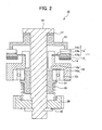
- Fig. 2 is a sectional view showing the ultrasonic motor of the first embodiment.
- the ultrasonic motor 10 of the first embodiment is a device that has a vibrating body (stator) 11 causing vibrations so as to generate vibration energy, and extracts the vibration energy as an output, thereby obtaining a driving force.
- a vibrating body (stator) 11 causing vibrations so as to generate vibration energy, and extracts the vibration energy as an output, thereby obtaining a driving force.
- the ultrasonic motor 10 is provided with the vibrating body 11 having a piezoelectric element 12 and an elastic body 13, and a moving body 15 (rotor) to be pressed into contact with a driving surface of the elastic body 13.
- the generation of a vibration wave in the vibrating body 11 causes relative movement between the vibrating body 11 and the moving body 15.
- the vibrating body 11 is firmly secured, and the moving body 15 moves relative to the vibrating body 11.
- the vibrating body 11 is provided with the piezoelectric element 12 as an electromechanical conversion element constructed to convert electrical energy to mechanical energy, and the elastic body 13 connecting the piezoelectric element 12.
- a progressive vibration wave (hereinafter referred to as "progressive wave") due to excitation of the piezoelectric element 12 occurs in the vibrating body 11.
- an electrostrictive element or the like may be used as an electromechanical conversion element.
- the elastic body 13 is an annular member formed by a metal material with a sharp resonance.
- the elastic body 13 is provided in contact with the piezoelectric element 12, and vibrates due to the drive of the piezoelectric element 12.
- a comb-finger part 13b provided with a groove is disposed on a surface opposite the surface to which the piezoelectric element 12 is connected.
- the front end face (a groove-free area) of the comb-finger part 13b serves as a driving surface, which is pressed into the moving body 15.
- the reason for forming the groove is to bring the neutral surface of the progressive wave as near to the side of the piezoelectric element 12 as possible, thereby increasing the amplitude of the progressive wave on the driving surface.
- the piezoelectric element 12 is connected to a surface of a base part 13a where no groove is formed, namely, the surface opposite to the groove.
- the elastic body 13 has its driving surface subjected to NiP surface treatment.
- the elastic body 13 has a flange part 13c on the inner peripheral side of the base part 13a, and the flange part 13c is used to fix the elastic body 13 to fixing members 16 (16a and 16b).
- the flange part 13c is located in the vicinity of the center in the thickness direction of the base part 13a.
- the piezoelectric element 12 is divided circumferentially into regions corresponding to two phases (A phase and B phase). In the regions corresponding to these two phases, elements of alternate polarity directions are arranged by a predetermined circumferential length.
- an FPC (flexible printed circuit) 14 is connected to the electrodes of the respective phases.
- a driving signal for exciting the piezoelectric element 12 is input through the FCP 14 to the piezoelectric element 12.
- the moving body 15 is provided contacting a portion of the vibrating body 11 different from the portion where the piezoelectric element 12 is provided.
- the moving body 15 is a member that moves relative to the vibrating body 11 due to the vibration of the elastic body 13.
- the moving body 15 is composed of a light metal such as aluminum, and an alumite surface treatment for improving the wear resistance is applied to the surface of a sliding face to be contacted with the vibrating body 11.
- An output shaft 18 is coupled to the rotator 15 with a rubber member 17 in between, and is integrally rotated with the rotator 15.
- the rubber member 17 between the output shaft 18 and the rotator 15 performs the function of connecting the rotator 15 and the output shaft 18 by the rubber's stickiness, and has the function of absorbing the vibration in order to prevent the transmission of the vibrations from the rotator 15 to the output shaft 18.
- the rubber member 17 is made of butyl rubber or the like.
- a pressurizing member 19 is, for example, a coil spring, and is provided between a gear member 20 fixed to the output shaft 18 and a bearing holder 21.
- the gear member 20 is inserted so as to be fitted into a D-cut of the output shaft 18, and is firmly secured by a stopper 22 such as an E-clip so that the gear member 20 can be integral with the output shaft 18 in a rotative direction and an axial direction.
- the bearing holder 21 is inserted into the inner diameter side of the bearing 23, and the bearing 23 is inserted into the inner diameter side of the fixing member 16a. With this arrangement, the rotator 15 can be pressed into contact with the driving surface of the vibrating body 11.
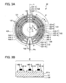
- Figs. 3A and 3B are drawings showing the details of the piezoelectric element 12 of the first embodiment.
- Fig. 3A is a plan view of the piezoelectric element 12
- Fig. 3B is a sectional view taken along the line B-B in Fig. 3A .
- the piezoelectric element 12 is provided with an A-phase piezoelectric element 12A and a B-phase piezoelectric element 12B, to which driving signals of different phases are respectively input.
- the A-phase piezoelectric element 12A and the B-phase piezoelectric element 12B are approximately bilaterally symmetric with respect to a line L passing through the center of the annular piezoelectric element 12.
- a plurality of electrodes 122 formed on the piezoelectric element 12 are provided at their respective corresponding positions of the A-phase piezoelectric element 12A and the B-phase piezoelectric element 12B. These electrodes 122 are arranged to be approximately bilaterally symmetric with respect to the line L.
- the piezoelectric element 12 is provided with a piezoelectric body 121 having a polarization part 121a polarized in a certain direction, which is represented by the slant lines, and a plurality of electrodes 122-4 to 122-6 formed separately and electrically independent from one another on the surface of a continuous region P of the polarization part 121a.
- an electrode 123 is formed on a surface opposite the surface on which the electrodes 122-4 to 122-6 of the piezoelectric body 12 are formed.
- the electrode 123 is divided neither radially nor circumferentially, that is, it is formed continuously over the entire surface of the piezoelectric body 14.
- the region P is in the shape of substantially a sector (a sector whose middle part is removed), and this region is polarized in a certain direction (for example, in the direction from the electrodes 122-4 to 122-6 to the electrode 123).
- the adjacent substantially sector-shaped region is polarized in the opposite direction to the region P.
- the piezoelectric body 121 has an annular shape, and the plurality of the electrodes 122-4 to 122-6 are arranged into sections (divisions) in the radial direction Y in the continuous region P of the piezoelectric body 121.
- the electrode 122 of the piezoelectric element 12 is also divided in the circumferential direction X (the electrodes 122-1, 122-4, 122-7 and 122-10; the electrodes 122-2, 122-5, 122-8 and 122-11; and the electrodes 122-3, 122-6, 122-9 and 122-12).
- the electrodes on the A-phase side have the same configuration.
- A-phase side FPCs 14A-1 to 14A-3, and B-phase side FPCs 14B-1 to 14B-3 are connected to the electrode 122 divided in the circumferential direction X, respectively (for example, the B-phase side FPC 14B-1 is connected to the electrodes 122-1, 122-4, 122-7 and 122-10), and wiring is arranged so that the driving signals can be respectively input independently to the electrodes divided in the circumferential direction X.
- the electrode 122-13 is a grounding electrode, to which a grounding FPC 14 is connected.
- the surface of the piezoelectric element 12 with the electrode 123 formed thereon is bonded to the elastic body 13 with adhesive.
- the elastic body 13 is grounded, and the grounding electrode 122-13 is connected to the elastic body 13 with a conductive material (not shown) in between.
- the grounding electrode 122-12 and the grounding FPC 14C are grounded.
- the electrode 123 of the piezoelectric element 12 is connected to the elastic body 13, and adhesive is interposed between the electrode 123 and the elastic body 13.
- the adhesive normally has no conductivity, there are portions where the electrode 123 and the elastic body 13 contact and become conductive towards each other, because the adhesive layer is thin and the surface on the side of the piezoelectric element 12 is rough. Hence, the electrode 123 of the piezoelectric element 12 and the elastic body 13 become conductive, and the electrode 123 is also grounded.
- the grounding electrode 122-13 is not divided.
- the grounding electrode 122-13 is provided between a portion corresponding to the A-phase and a portion corresponding to the B-phase in the circumferential direction on the piezoelectric element 12.
- the circumferential length of the grounding electrode 122-13 corresponds to a quarter-wavelength of the wavelength of the vibration wave to be generated in the piezoelectric element 12 when the driving signal is input to the A-phase or the B-phase electrode.
- the circumferential lengths of the electrodes 122-4 to 122-6 and the electrodes 122-7 to 122-9 correspond to a half-wavelength of the wavelength of the vibration wave to be generated in the piezoelectric element 12 when the driving signal is input to the B-phase electrode.
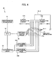
- Fig. 4 is a diagram showing an ultrasonic motor driving device in the first embodiment.
- the ultrasonic motor driving device 30 is provided with an ambient temperature detecting section 31, an MCU (micro control unit) 32, a pulse generation circuit 33, an A-phase driving signal generation circuit 34A, a B-phase driving signal generation circuit 34B, wiring sections 35-1, a wiring section 35-2, a switching control circuit 36 and a power supply switching section 37.
- MCU micro control unit
- A-phase driving signal generation circuit 34A A-phase driving signal generation circuit 34A
- B-phase driving signal generation circuit 34B wiring sections 35-1, a wiring section 35-2, a switching control circuit 36 and a power supply switching section 37.
- the ambient temperature detecting section 31 is a device to detect the ambient temperature and send the detection results such as temperature information to the MCU 32.
- the ambient temperature detecting section 31 is disposed so that it can detect the temperature of the piezoelectric element 12 or its surroundings. This enables more direct measurement of the temperature close to the temperature of the piezoelectric element 12.
- the MCU 32 is a section to generally control the ultrasonic motor driving device 30, and control the pulse generation circuit 33 and the switching control circuit 36.
- the MCU 32 also controls the driving signal supply conditions in response to the detection result obtained at the ambient temperature detecting section 31.
- the uniformity between the driving characteristics at high temperatures and those at low temperatures can be achieved, for example, by reducing the number of electrodes to supply the driving signal at high temperatures compared to low temperatures.
- the pulse generation circuit 33 is a circuit to generate pulse signals for driving the A-phase piezoelectric element 12A and the B-phase piezoelectric element 12B of the ultrasonic motor 10.
- the A-phase driving signal generation circuit 34A is a circuit to generate driving signals for the A-phase piezoelectric element 12A, based on the pulse signal from the pulse generation circuit 33.
- the B-phase driving signal generation circuit 34B is a circuit to generate driving signals for the B-phase piezoelectric element 12B, based on the pulse signal from the pulse generation circuit 33.
- the A-phase and the B-phase driving signal generation circuits 34A and 34B can independently supply the driving signals to individual wiring parts of the plurality of the wiring sections 35-1.
- the wiring sections 35-1 are for connecting the A-phase driving signal generation circuit 34A and A-phase side FPCs 14A-1 to 14A-3 disposed correspondingly to the inner peripheral side, the central side and the outer peripheral side electrodes 122, respectively, and for connecting the B-phase driving signal generation circuit 34B and B-phase side FPCs 14B-1 to 14B-3 disposed correspondingly to the inner peripheral side, the central side and the outer peripheral side electrodes 122, respectively.
- the wiring sections 35-1 are for inputting the driving signals to be output from the A-phase and the B-phase driving signal generation circuits 34A and 34B to the A-phase and the B-phase piezoelectric elements 12A and 12B, respectively.
- the wiring section 35-2 is wiring to ground the grounding FPC 14C via the grounding electrode 122-13.
- the grounding of the grounding FPC 14C is attained by connecting the grounding electrode 122-13 via the conductive material to the elastic body 13, as described above.
- the electrode 123 formed on the back of the piezoelectric element 12 is also grounded by becoming conductive with the elastic body 13, as described above.
- the switching control circuit 36 controls the ON/OFF of a FET (field effect transistor) 37a, based on the instruction from the MCU 32.
- the power supply switching section 37 is independently switchable between the supply and the non-supply of driving signals to the A-phase side FPCs 14A-1 to 14A-3, and to the B-phase side FPCs 14B-1 to 14B-3 by the FET 37a as an electrical switching element.
- the MCU 32 sends a driving instruction to the pulse generation circuit 33.
- the A-phase and the B-phase driving signal generation circuits 34A and 34B generate driving signals, respectively, based on the pulse signals from the pulse generation circuit 33.
- the generated driving signals are simultaneously input via the A-phase side FPCs 14A-1 to 14A-3, and the B-phase side FPCs 14B-1 to 14B-3, to the A-phase and the B-phase piezoelectric elements 12A and 12B, respectively.
- the MCU 32 Upon the receipt of the temperature information from the ambient temperature detecting section 31, the MCU 32 sends an instruction to the switching control circuit 36. Based on the instruction from the switching control circuit 36, the power supply switching section 37 performs switching of the supply of the driving signal.
- the MCU 32 initially drives the piezoelectric element 12 in the entire region.
- the MCU 32 judges a temperature increase, and sends an instruction for reducing the number of the wiring sections 35-1 to supply driving signals compared to low temperatures, to the switching control circuit 36.
- the MCU 32 further sends an instruction for supplying driving signals to electrodes having a symmetrical relationship with each other in the A-phase and the B-phase piezoelectric elements 12A and 12B, respectively, to the switching control circuit 36.
- the supply of driving signals to the inner peripheral electrodes of the A-phase and the B-phase piezoelectric elements 12A and 12B may be stopped, or the supply of driving signals to the outer peripheral electrodes of the A-phase and the B-phase piezoelectric elements 12A and 12B may be stopped.
- the inner peripheral electrode having a small area may be controlled. If a large change of the electrostatic capacity value is desired, the outer peripheral electrode having a large area may be controlled.
- the first embodiment produces the following effects.
- Fig. 5 is a drawing showing a piezoelectric element according to a second embodiment. For parts having the same function as the first embodiment, overlapping descriptions and drawings are omitted.
- the piezoelectric element 12-2 of the second embodiment is different from the piezoelectric element 12 of the first embodiment in the method of dividing the electrodes, that is, the electrodes 122 are divided only in the circumferential direction X.
- the A-phase side FPCs 14A-1 to 14A-4, and the B-phase side FPCs 14B-1 to 14B-4 are connected to the electrodes 122 divided in the circumferential direction X.
- These A-phase side FPCs 14A-1 to 14-4 and these B-phase side FPCs 14B-1 to 14B-4 are wired independently for each electrode, enabling the driving signals to be input independently to each electrode.
- the wiring sections 35-1 of the abovementioned ultrasonic motor 30 are connected to these FPCs, respectively, and driven in the same manner as the first embodiment.
- the wiring of the wiring sections 35-1 requires eight wires, which is greater than the number in the first embodiment by two.
- the abovementioned piezoelectric element 12-2 can perform driving in accordance with temperature, drive velocity, intended use and the like, as in the case with the first embodiment.
- Fig. 6 is a drawing showing a modification of the piezoelectric body.
- the piezoelectric body 121 has the polarization part 121a polarized in a certain direction substantially over the entire surface, as described with reference to Fig. 3B .
- an unpolarized portion may be provided at a position corresponding to the boundary portions of a plurality of electrodes.
- the polarization part 121a consists of three separated polarized portions with an unpolarized portion in between.
- the term "polarization part" in the present specification is a concept including an embodiment where two or more polarization parts are arranged with an unpolarized portion in between.
- the embodiment shown in Fig. 3B corresponds to the case where the narrow space between the radically arranged electrodes 122 enables complete polarization even at the boundary portion between the electrodes, and the case where the electrode 122 is formed on substantially the entire surface, and part of the electrode is then removed.
- the embodiment shown in Fig. 6 corresponds to the case where the space between the electrodes 122 is slightly larger than that in Fig. 3B , failing to obtain complete polarization at the boundary portion between the electrodes.
Landscapes
- Physics & Mathematics (AREA)
- General Physics & Mathematics (AREA)
- Optics & Photonics (AREA)
- General Electrical Machinery Utilizing Piezoelectricity, Electrostriction Or Magnetostriction (AREA)
- Lens Barrels (AREA)
Applications Claiming Priority (1)
| Application Number | Priority Date | Filing Date | Title |
|---|---|---|---|
| JP2007092925A JP5343322B2 (ja) | 2007-03-30 | 2007-03-30 | 振動アクチュエータの駆動装置、レンズ鏡筒及びカメラ |
Publications (3)
| Publication Number | Publication Date |
|---|---|
| EP1976037A2 EP1976037A2 (en) | 2008-10-01 |
| EP1976037A3 EP1976037A3 (en) | 2011-01-12 |
| EP1976037B1 true EP1976037B1 (en) | 2012-05-30 |
Family
ID=39651215
Family Applications (1)
| Application Number | Title | Priority Date | Filing Date |
|---|---|---|---|
| EP20080006045 Not-in-force EP1976037B1 (en) | 2007-03-30 | 2008-03-28 | Electromechanical conversion element, vibration actuator, vibration actuator driving device, lens barrel and camera |
Country Status (4)
| Country | Link |
|---|---|
| US (2) | US7732980B2 (ja) |
| EP (1) | EP1976037B1 (ja) |
| JP (1) | JP5343322B2 (ja) |
| KR (1) | KR101524447B1 (ja) |
Families Citing this family (12)
| Publication number | Priority date | Publication date | Assignee | Title |
|---|---|---|---|---|
| WO2007108466A1 (ja) * | 2006-03-22 | 2007-09-27 | Nikon Corporation | 振動子、振動アクチュエータ、レンズ鏡筒、カメラシステム及び振動アクチュエータの駆動方法 |
| CN101569085B (zh) * | 2006-12-25 | 2013-01-23 | 株式会社尼康 | 振动致动器、镜头镜筒、照相机 |
| JP4561894B2 (ja) * | 2008-07-14 | 2010-10-13 | 株式会社村田製作所 | 圧電モータ及びその製造方法 |
| FR2950154B1 (fr) * | 2009-09-15 | 2011-12-23 | Commissariat Energie Atomique | Dispositif optique a membrane deformable a actionnement piezoelectrique en forme de couronne continue |
| JP5540188B2 (ja) * | 2009-10-29 | 2014-07-02 | 新シコー科技株式会社 | リニア駆動装置 |
| JP2012210024A (ja) * | 2011-03-29 | 2012-10-25 | Nikon Corp | 振動体、振動アクチュエータ、レンズ鏡筒、カメラ及び振動体の接合方法 |
| JP5832373B2 (ja) * | 2012-05-16 | 2015-12-16 | キヤノン株式会社 | 交換レンズ装置およびカメラ装置 |
| US8730599B2 (en) | 2012-10-01 | 2014-05-20 | Apple Inc. | Piezoelectric and MEMS actuator |
| JP6460833B2 (ja) * | 2015-02-25 | 2019-01-30 | キヤノン株式会社 | 振動体、振動体の駆動方法、振動型駆動装置、塵埃除去装置及び撮像装置 |
| FR3042660B1 (fr) * | 2015-10-16 | 2018-04-06 | Airbus Helicopters | Actionneur electromecanique pour commandes de vol electriques d'un aeronef |
| KR102421717B1 (ko) * | 2015-11-24 | 2022-07-18 | 삼성전자주식회사 | 촬상 장치 모듈, 이를 포함하는 사용자 단말 장치 |
| JP2017175696A (ja) * | 2016-03-22 | 2017-09-28 | セイコーエプソン株式会社 | 圧電駆動装置の制御回路、圧電駆動装置、超音波モーター、ロボット、ハンド、及びポンプ |
Family Cites Families (28)
| Publication number | Priority date | Publication date | Assignee | Title |
|---|---|---|---|---|
| CA1208269A (en) | 1982-02-25 | 1986-07-22 | Toshiiku Sashida | Motor device utilizing ultrasonic oscillation |
| US4831305A (en) * | 1984-04-02 | 1989-05-16 | Canon Kabushiki Kaisha | Vibration wave motor |
| JPH0244531Y2 (ja) * | 1985-12-24 | 1990-11-27 | ||
| DE3782301T2 (de) * | 1986-02-18 | 1993-02-25 | Matsushita Electric Ind Co Ltd | Ultraschallmotor. |
| US4882500A (en) * | 1986-06-04 | 1989-11-21 | Nippon Seimitsu Kogyo Kabushiki Kaisha | Method for converting standing wave vibrations into motion and standing wave motor therefor |
| JP2532425B2 (ja) * | 1986-12-26 | 1996-09-11 | オリンパス光学工業株式会社 | 超音波モ−タ |
| JPS648874A (en) * | 1987-06-29 | 1989-01-12 | Kyocera Corp | Temperature controlled surface wave motor |
| CN1035213A (zh) * | 1987-12-29 | 1989-08-30 | 精工电子工业株式会社 | 行波电机 |
| US5625246A (en) * | 1988-10-19 | 1997-04-29 | Nikon Corporation | Driving control device for vibration wave motor |
| JPH072029B2 (ja) * | 1989-06-26 | 1995-01-11 | セイコー電子工業株式会社 | 超音波モータ |
| US5237237A (en) * | 1990-03-12 | 1993-08-17 | Seiko Epson Corporation | Ultrasonic motor and drive method |
| JPH0421371A (ja) * | 1990-05-15 | 1992-01-24 | Canon Inc | 振動波モータ |
| JPH05137355A (ja) * | 1991-11-12 | 1993-06-01 | Canon Inc | 振動波モータ |
| US5616980A (en) * | 1993-07-09 | 1997-04-01 | Nanomotion Ltd. | Ceramic motor |
| JPH07115782A (ja) * | 1993-10-13 | 1995-05-02 | Canon Inc | 振動波駆動装置 |
| JP3220365B2 (ja) | 1995-10-06 | 2001-10-22 | 京セラ株式会社 | 超音波モータの速度制御方式 |
| JPH10290589A (ja) * | 1997-04-14 | 1998-10-27 | Minolta Co Ltd | 電気機械変換素子を使用した駆動装置 |
| JPH11318089A (ja) * | 1998-05-07 | 1999-11-16 | Seiko Instruments Inc | 超音波モータ付き部品及びこれを用いた電子機器 |
| JP2000060156A (ja) * | 1998-08-12 | 2000-02-25 | Mitsuba Corp | 超音波モータ |
| US6943481B2 (en) * | 2001-06-05 | 2005-09-13 | Canon Precision Kabushiki Kaisha | Vibration member and vibration wave driving apparatus |
| JP2003033056A (ja) * | 2001-07-10 | 2003-01-31 | Nidec Copal Corp | 超音波モータ制御回路 |
| JP4086536B2 (ja) * | 2002-04-18 | 2008-05-14 | キヤノン株式会社 | 振動波駆動装置及びその駆動回路 |
| JP2004126009A (ja) * | 2002-09-30 | 2004-04-22 | Toshiba Corp | ズームレンズユニット及びズームレンズユニット駆動方法 |
| JP4374959B2 (ja) * | 2003-09-16 | 2009-12-02 | セイコーエプソン株式会社 | 圧電アクチュエータ、この圧電アクチュエータを用いた機器 |
| JP4497980B2 (ja) * | 2004-03-30 | 2010-07-07 | キヤノン株式会社 | 圧電体およびその分極方法 |
| JP4594034B2 (ja) * | 2004-10-26 | 2010-12-08 | キヤノン株式会社 | 振動型駆動装置、その制御装置及びその制御方法 |
| JP2007092925A (ja) | 2005-09-29 | 2007-04-12 | Chugoku Electric Power Co Inc:The | ボルト |
| US7786648B2 (en) * | 2008-08-18 | 2010-08-31 | New Scale Technologies | Semi-resonant driving systems and methods thereof |
-
2007
- 2007-03-30 JP JP2007092925A patent/JP5343322B2/ja not_active Expired - Fee Related
-
2008
- 2008-03-26 KR KR1020080027936A patent/KR101524447B1/ko active IP Right Grant
- 2008-03-27 US US12/056,855 patent/US7732980B2/en not_active Expired - Fee Related
- 2008-03-28 EP EP20080006045 patent/EP1976037B1/en not_active Not-in-force
-
2010
- 2010-04-26 US US12/767,769 patent/US8013494B2/en not_active Expired - Fee Related
Also Published As
| Publication number | Publication date |
|---|---|
| US20080265714A1 (en) | 2008-10-30 |
| US20100201225A1 (en) | 2010-08-12 |
| US7732980B2 (en) | 2010-06-08 |
| US8013494B2 (en) | 2011-09-06 |
| KR101524447B1 (ko) | 2015-06-01 |
| EP1976037A3 (en) | 2011-01-12 |
| EP1976037A2 (en) | 2008-10-01 |
| KR20080089211A (ko) | 2008-10-06 |
| JP2008253078A (ja) | 2008-10-16 |
| JP5343322B2 (ja) | 2013-11-13 |
Similar Documents
| Publication | Publication Date | Title |
|---|---|---|
| EP1976037B1 (en) | Electromechanical conversion element, vibration actuator, vibration actuator driving device, lens barrel and camera | |
| US20100039715A1 (en) | Reduced-voltage, linear motor systems and methods thereof | |
| JP6056224B2 (ja) | 振動波モータ | |
| US8035276B2 (en) | Vibration actuator, lens barrel and camera | |
| JPH08182357A (ja) | 超音波モータの駆動回路 | |
| JP5433991B2 (ja) | 振動アクチュエータ、レンズ鏡筒及びカメラ | |
| JPWO2008078640A1 (ja) | 振動アクチュエータ、レンズ鏡筒、カメラ | |
| US8159763B2 (en) | Vibrating element, vibration actuator, lens barrel, camera system and method for driving vibration actuator | |
| JP4976844B2 (ja) | 多自由度駆動装置および撮像装置 | |
| JP6025446B2 (ja) | 振動型アクチュエータ、撮像装置および、振動型アクチュエータを備えた装置 | |
| US20090207512A1 (en) | Vibration actuator, lens barrel and camera | |
| US5821669A (en) | Vibration wave motor having piezoelectric pressure member | |
| JP6671883B2 (ja) | 振動型アクチュエータの制御装置とその制御方法、振動装置、交換用レンズ、撮像装置、及び自動ステージ | |
| JP2010124649A (ja) | 振動アクチュエータ、レンズ鏡筒および光学機器 | |
| JP5326325B2 (ja) | 振動アクチュエータ、レンズ鏡筒、光学機器 | |
| JPH10210776A (ja) | 回転直動一体型超音波モータ及びそれを内蔵した電子機器 | |
| JP2008253077A (ja) | 振動アクチュエータ,レンズ鏡筒及びカメラ | |
| JPS63117670A (ja) | 超音波モータを利用した駆動装置 | |
| JP4945023B2 (ja) | 電気−機械変換素子、超音波モータおよび電子機器 | |
| JPH112752A (ja) | 振動アクチュエータ駆動装置とレンズ鏡筒 | |
| JPS62236368A (ja) | 超音波モ−タ | |
| JP5292954B2 (ja) | 振動アクチュエータ及びレンズ鏡筒 | |
| JP3817825B2 (ja) | 振動アクチュエータ | |
| JP2008259325A (ja) | 振動アクチュエータ装置、レンズ鏡筒、カメラ | |
| JP2010226854A (ja) | 振動アクチュエータ、それを備えたレンズ鏡筒及びカメラ |
Legal Events
| Date | Code | Title | Description |
|---|---|---|---|
| PUAI | Public reference made under article 153(3) epc to a published international application that has entered the european phase |
Free format text: ORIGINAL CODE: 0009012 |
|
| AK | Designated contracting states |
Kind code of ref document: A2 Designated state(s): AT BE BG CH CY CZ DE DK EE ES FI FR GB GR HR HU IE IS IT LI LT LU LV MC MT NL NO PL PT RO SE SI SK TR |
|
| AX | Request for extension of the european patent |
Extension state: AL BA MK RS |
|
| RAP1 | Party data changed (applicant data changed or rights of an application transferred) |
Owner name: NIKON CORPORATION |
|
| PUAL | Search report despatched |
Free format text: ORIGINAL CODE: 0009013 |
|
| AK | Designated contracting states |
Kind code of ref document: A3 Designated state(s): AT BE BG CH CY CZ DE DK EE ES FI FR GB GR HR HU IE IS IT LI LT LU LV MC MT NL NO PL PT RO SE SI SK TR |
|
| AX | Request for extension of the european patent |
Extension state: AL BA MK RS |
|
| 17P | Request for examination filed |
Effective date: 20110711 |
|
| AKX | Designation fees paid |
Designated state(s): AT BE BG CH CY CZ DE DK EE ES FI FR GB GR HR HU IE IS IT LI LT LU LV MC MT NL NO PL PT RO SE SI SK TR |
|
| REG | Reference to a national code |
Ref country code: DE Ref legal event code: R079 Ref document number: 602008015960 Country of ref document: DE Free format text: PREVIOUS MAIN CLASS: H01L0041090000 Ipc: H01L0041040000 |
|
| GRAP | Despatch of communication of intention to grant a patent |
Free format text: ORIGINAL CODE: EPIDOSNIGR1 |
|
| RIC1 | Information provided on ipc code assigned before grant |
Ipc: H01L 41/04 20060101AFI20111104BHEP Ipc: H01L 41/09 20060101ALI20111104BHEP |
|
| RIN1 | Information on inventor provided before grant (corrected) |
Inventor name: MORIOKE, TOSHIKAZU |
|
| GRAS | Grant fee paid |
Free format text: ORIGINAL CODE: EPIDOSNIGR3 |
|
| GRAA | (expected) grant |
Free format text: ORIGINAL CODE: 0009210 |
|
| AK | Designated contracting states |
Kind code of ref document: B1 Designated state(s): AT BE BG CH CY CZ DE DK EE ES FI FR GB GR HR HU IE IS IT LI LT LU LV MC MT NL NO PL PT RO SE SI SK TR |
|
| REG | Reference to a national code |
Ref country code: GB Ref legal event code: FG4D |
|
| REG | Reference to a national code |
Ref country code: CH Ref legal event code: EP |
|
| REG | Reference to a national code |
Ref country code: AT Ref legal event code: REF Ref document number: 560416 Country of ref document: AT Kind code of ref document: T Effective date: 20120615 |
|
| REG | Reference to a national code |
Ref country code: IE Ref legal event code: FG4D |
|
| REG | Reference to a national code |
Ref country code: DE Ref legal event code: R096 Ref document number: 602008015960 Country of ref document: DE Effective date: 20120726 |
|
| REG | Reference to a national code |
Ref country code: NL Ref legal event code: VDEP Effective date: 20120530 |
|
| REG | Reference to a national code |
Ref country code: LT Ref legal event code: MG4D Effective date: 20120530 |
|
| PG25 | Lapsed in a contracting state [announced via postgrant information from national office to epo] |
Ref country code: FI Free format text: LAPSE BECAUSE OF FAILURE TO SUBMIT A TRANSLATION OF THE DESCRIPTION OR TO PAY THE FEE WITHIN THE PRESCRIBED TIME-LIMIT Effective date: 20120530 Ref country code: SE Free format text: LAPSE BECAUSE OF FAILURE TO SUBMIT A TRANSLATION OF THE DESCRIPTION OR TO PAY THE FEE WITHIN THE PRESCRIBED TIME-LIMIT Effective date: 20120530 Ref country code: CY Free format text: LAPSE BECAUSE OF FAILURE TO SUBMIT A TRANSLATION OF THE DESCRIPTION OR TO PAY THE FEE WITHIN THE PRESCRIBED TIME-LIMIT Effective date: 20120530 Ref country code: NO Free format text: LAPSE BECAUSE OF FAILURE TO SUBMIT A TRANSLATION OF THE DESCRIPTION OR TO PAY THE FEE WITHIN THE PRESCRIBED TIME-LIMIT Effective date: 20120830 Ref country code: IS Free format text: LAPSE BECAUSE OF FAILURE TO SUBMIT A TRANSLATION OF THE DESCRIPTION OR TO PAY THE FEE WITHIN THE PRESCRIBED TIME-LIMIT Effective date: 20120930 Ref country code: LT Free format text: LAPSE BECAUSE OF FAILURE TO SUBMIT A TRANSLATION OF THE DESCRIPTION OR TO PAY THE FEE WITHIN THE PRESCRIBED TIME-LIMIT Effective date: 20120530 |
|
| REG | Reference to a national code |
Ref country code: AT Ref legal event code: MK05 Ref document number: 560416 Country of ref document: AT Kind code of ref document: T Effective date: 20120530 |
|
| PG25 | Lapsed in a contracting state [announced via postgrant information from national office to epo] |
Ref country code: SI Free format text: LAPSE BECAUSE OF FAILURE TO SUBMIT A TRANSLATION OF THE DESCRIPTION OR TO PAY THE FEE WITHIN THE PRESCRIBED TIME-LIMIT Effective date: 20120530 Ref country code: GR Free format text: LAPSE BECAUSE OF FAILURE TO SUBMIT A TRANSLATION OF THE DESCRIPTION OR TO PAY THE FEE WITHIN THE PRESCRIBED TIME-LIMIT Effective date: 20120831 Ref country code: HR Free format text: LAPSE BECAUSE OF FAILURE TO SUBMIT A TRANSLATION OF THE DESCRIPTION OR TO PAY THE FEE WITHIN THE PRESCRIBED TIME-LIMIT Effective date: 20120530 Ref country code: LV Free format text: LAPSE BECAUSE OF FAILURE TO SUBMIT A TRANSLATION OF THE DESCRIPTION OR TO PAY THE FEE WITHIN THE PRESCRIBED TIME-LIMIT Effective date: 20120530 |
|
| PG25 | Lapsed in a contracting state [announced via postgrant information from national office to epo] |
Ref country code: BE Free format text: LAPSE BECAUSE OF FAILURE TO SUBMIT A TRANSLATION OF THE DESCRIPTION OR TO PAY THE FEE WITHIN THE PRESCRIBED TIME-LIMIT Effective date: 20120530 |
|
| PG25 | Lapsed in a contracting state [announced via postgrant information from national office to epo] |
Ref country code: SK Free format text: LAPSE BECAUSE OF FAILURE TO SUBMIT A TRANSLATION OF THE DESCRIPTION OR TO PAY THE FEE WITHIN THE PRESCRIBED TIME-LIMIT Effective date: 20120530 Ref country code: AT Free format text: LAPSE BECAUSE OF FAILURE TO SUBMIT A TRANSLATION OF THE DESCRIPTION OR TO PAY THE FEE WITHIN THE PRESCRIBED TIME-LIMIT Effective date: 20120530 Ref country code: DK Free format text: LAPSE BECAUSE OF FAILURE TO SUBMIT A TRANSLATION OF THE DESCRIPTION OR TO PAY THE FEE WITHIN THE PRESCRIBED TIME-LIMIT Effective date: 20120530 Ref country code: CZ Free format text: LAPSE BECAUSE OF FAILURE TO SUBMIT A TRANSLATION OF THE DESCRIPTION OR TO PAY THE FEE WITHIN THE PRESCRIBED TIME-LIMIT Effective date: 20120530 Ref country code: NL Free format text: LAPSE BECAUSE OF FAILURE TO SUBMIT A TRANSLATION OF THE DESCRIPTION OR TO PAY THE FEE WITHIN THE PRESCRIBED TIME-LIMIT Effective date: 20120530 Ref country code: EE Free format text: LAPSE BECAUSE OF FAILURE TO SUBMIT A TRANSLATION OF THE DESCRIPTION OR TO PAY THE FEE WITHIN THE PRESCRIBED TIME-LIMIT Effective date: 20120530 Ref country code: RO Free format text: LAPSE BECAUSE OF FAILURE TO SUBMIT A TRANSLATION OF THE DESCRIPTION OR TO PAY THE FEE WITHIN THE PRESCRIBED TIME-LIMIT Effective date: 20120530 |
|
| PG25 | Lapsed in a contracting state [announced via postgrant information from national office to epo] |
Ref country code: IT Free format text: LAPSE BECAUSE OF FAILURE TO SUBMIT A TRANSLATION OF THE DESCRIPTION OR TO PAY THE FEE WITHIN THE PRESCRIBED TIME-LIMIT Effective date: 20120530 Ref country code: PL Free format text: LAPSE BECAUSE OF FAILURE TO SUBMIT A TRANSLATION OF THE DESCRIPTION OR TO PAY THE FEE WITHIN THE PRESCRIBED TIME-LIMIT Effective date: 20120530 Ref country code: PT Free format text: LAPSE BECAUSE OF FAILURE TO SUBMIT A TRANSLATION OF THE DESCRIPTION OR TO PAY THE FEE WITHIN THE PRESCRIBED TIME-LIMIT Effective date: 20121001 |
|
| PLBE | No opposition filed within time limit |
Free format text: ORIGINAL CODE: 0009261 |
|
| STAA | Information on the status of an ep patent application or granted ep patent |
Free format text: STATUS: NO OPPOSITION FILED WITHIN TIME LIMIT |
|
| PG25 | Lapsed in a contracting state [announced via postgrant information from national office to epo] |
Ref country code: ES Free format text: LAPSE BECAUSE OF FAILURE TO SUBMIT A TRANSLATION OF THE DESCRIPTION OR TO PAY THE FEE WITHIN THE PRESCRIBED TIME-LIMIT Effective date: 20120910 |
|
| 26N | No opposition filed |
Effective date: 20130301 |
|
| REG | Reference to a national code |
Ref country code: DE Ref legal event code: R097 Ref document number: 602008015960 Country of ref document: DE Effective date: 20130301 |
|
| PG25 | Lapsed in a contracting state [announced via postgrant information from national office to epo] |
Ref country code: BG Free format text: LAPSE BECAUSE OF FAILURE TO SUBMIT A TRANSLATION OF THE DESCRIPTION OR TO PAY THE FEE WITHIN THE PRESCRIBED TIME-LIMIT Effective date: 20120830 |
|
| PG25 | Lapsed in a contracting state [announced via postgrant information from national office to epo] |
Ref country code: MC Free format text: LAPSE BECAUSE OF NON-PAYMENT OF DUE FEES Effective date: 20130331 |
|
| REG | Reference to a national code |
Ref country code: CH Ref legal event code: PL |
|
| REG | Reference to a national code |
Ref country code: IE Ref legal event code: MM4A |
|
| PG25 | Lapsed in a contracting state [announced via postgrant information from national office to epo] |
Ref country code: IE Free format text: LAPSE BECAUSE OF NON-PAYMENT OF DUE FEES Effective date: 20130328 Ref country code: CH Free format text: LAPSE BECAUSE OF NON-PAYMENT OF DUE FEES Effective date: 20130331 Ref country code: LI Free format text: LAPSE BECAUSE OF NON-PAYMENT OF DUE FEES Effective date: 20130331 |
|
| PG25 | Lapsed in a contracting state [announced via postgrant information from national office to epo] |
Ref country code: MT Free format text: LAPSE BECAUSE OF FAILURE TO SUBMIT A TRANSLATION OF THE DESCRIPTION OR TO PAY THE FEE WITHIN THE PRESCRIBED TIME-LIMIT Effective date: 20120530 |
|
| PG25 | Lapsed in a contracting state [announced via postgrant information from national office to epo] |
Ref country code: TR Free format text: LAPSE BECAUSE OF FAILURE TO SUBMIT A TRANSLATION OF THE DESCRIPTION OR TO PAY THE FEE WITHIN THE PRESCRIBED TIME-LIMIT Effective date: 20120530 |
|
| PG25 | Lapsed in a contracting state [announced via postgrant information from national office to epo] |
Ref country code: HU Free format text: LAPSE BECAUSE OF FAILURE TO SUBMIT A TRANSLATION OF THE DESCRIPTION OR TO PAY THE FEE WITHIN THE PRESCRIBED TIME-LIMIT; INVALID AB INITIO Effective date: 20080328 Ref country code: LU Free format text: LAPSE BECAUSE OF NON-PAYMENT OF DUE FEES Effective date: 20130328 |
|
| REG | Reference to a national code |
Ref country code: FR Ref legal event code: PLFP Year of fee payment: 9 |
|
| REG | Reference to a national code |
Ref country code: FR Ref legal event code: PLFP Year of fee payment: 10 |
|
| REG | Reference to a national code |
Ref country code: FR Ref legal event code: PLFP Year of fee payment: 11 |
|
| PGFP | Annual fee paid to national office [announced via postgrant information from national office to epo] |
Ref country code: GB Payment date: 20200318 Year of fee payment: 13 Ref country code: DE Payment date: 20200317 Year of fee payment: 13 |
|
| PGFP | Annual fee paid to national office [announced via postgrant information from national office to epo] |
Ref country code: FR Payment date: 20200214 Year of fee payment: 13 |
|
| REG | Reference to a national code |
Ref country code: DE Ref legal event code: R119 Ref document number: 602008015960 Country of ref document: DE |
|
| GBPC | Gb: european patent ceased through non-payment of renewal fee |
Effective date: 20210328 |
|
| PG25 | Lapsed in a contracting state [announced via postgrant information from national office to epo] |
Ref country code: FR Free format text: LAPSE BECAUSE OF NON-PAYMENT OF DUE FEES Effective date: 20210331 Ref country code: GB Free format text: LAPSE BECAUSE OF NON-PAYMENT OF DUE FEES Effective date: 20210328 Ref country code: DE Free format text: LAPSE BECAUSE OF NON-PAYMENT OF DUE FEES Effective date: 20211001 |