EP1975623A2 - Analyseur d'échantillon - Google Patents
Analyseur d'échantillon Download PDFInfo
- Publication number
- EP1975623A2 EP1975623A2 EP08004572A EP08004572A EP1975623A2 EP 1975623 A2 EP1975623 A2 EP 1975623A2 EP 08004572 A EP08004572 A EP 08004572A EP 08004572 A EP08004572 A EP 08004572A EP 1975623 A2 EP1975623 A2 EP 1975623A2
- Authority
- EP
- European Patent Office
- Prior art keywords
- calibration curve
- reagent
- storage means
- sample
- measurement
- Prior art date
- Legal status (The legal status is an assumption and is not a legal conclusion. Google has not performed a legal analysis and makes no representation as to the accuracy of the status listed.)
- Granted
Links
- 238000011088 calibration curve Methods 0.000 claims abstract description 330
- 239000003153 chemical reaction reagent Substances 0.000 claims abstract description 283
- 238000005259 measurement Methods 0.000 claims abstract description 155
- 238000012545 processing Methods 0.000 claims abstract description 17
- 238000000034 method Methods 0.000 claims abstract description 11
- 238000004064 recycling Methods 0.000 claims description 33
- 238000010200 validation analysis Methods 0.000 claims description 9
- 239000006249 magnetic particle Substances 0.000 description 40
- 238000006243 chemical reaction Methods 0.000 description 37
- 239000000427 antigen Substances 0.000 description 36
- 102000036639 antigens Human genes 0.000 description 36
- 108091007433 antigens Proteins 0.000 description 36
- 238000003756 stirring Methods 0.000 description 33
- 238000010517 secondary reaction Methods 0.000 description 21
- 238000005406 washing Methods 0.000 description 21
- 239000000758 substrate Substances 0.000 description 15
- 239000007788 liquid Substances 0.000 description 10
- 230000007246 mechanism Effects 0.000 description 10
- 238000012360 testing method Methods 0.000 description 9
- 238000004590 computer program Methods 0.000 description 8
- 238000004891 communication Methods 0.000 description 7
- 210000004369 blood Anatomy 0.000 description 6
- 239000008280 blood Substances 0.000 description 6
- 238000007599 discharging Methods 0.000 description 6
- 238000009434 installation Methods 0.000 description 6
- 239000002699 waste material Substances 0.000 description 6
- 239000006185 dispersion Substances 0.000 description 5
- 239000000126 substance Substances 0.000 description 5
- 239000000428 dust Substances 0.000 description 4
- 238000011534 incubation Methods 0.000 description 4
- 239000011295 pitch Substances 0.000 description 4
- 230000005856 abnormality Effects 0.000 description 3
- 230000023555 blood coagulation Effects 0.000 description 3
- 230000001939 inductive effect Effects 0.000 description 3
- 238000000926 separation method Methods 0.000 description 3
- 230000005540 biological transmission Effects 0.000 description 2
- 238000010586 diagram Methods 0.000 description 2
- 208000002672 hepatitis B Diseases 0.000 description 2
- 239000000439 tumor marker Substances 0.000 description 2
- 208000005176 Hepatitis C Diseases 0.000 description 1
- AUYYCJSJGJYCDS-LBPRGKRZSA-N Thyrolar Chemical class IC1=CC(C[C@H](N)C(O)=O)=CC(I)=C1OC1=CC=C(O)C(I)=C1 AUYYCJSJGJYCDS-LBPRGKRZSA-N 0.000 description 1
- 238000002835 absorbance Methods 0.000 description 1
- 230000015271 coagulation Effects 0.000 description 1
- 238000005345 coagulation Methods 0.000 description 1
- 238000011835 investigation Methods 0.000 description 1
- 238000000691 measurement method Methods 0.000 description 1
- 239000000203 mixture Substances 0.000 description 1
- 230000003287 optical effect Effects 0.000 description 1
- 210000002381 plasma Anatomy 0.000 description 1
- 230000000717 retained effect Effects 0.000 description 1
- 239000007790 solid phase Substances 0.000 description 1
- 239000005495 thyroid hormone Substances 0.000 description 1
- 229940036555 thyroid hormone Drugs 0.000 description 1
Images


Classifications
-
- G—PHYSICS
- G01—MEASURING; TESTING
- G01N—INVESTIGATING OR ANALYSING MATERIALS BY DETERMINING THEIR CHEMICAL OR PHYSICAL PROPERTIES
- G01N35/00—Automatic analysis not limited to methods or materials provided for in any single one of groups G01N1/00 - G01N33/00; Handling materials therefor
- G01N35/00584—Control arrangements for automatic analysers
- G01N35/00594—Quality control, including calibration or testing of components of the analyser
- G01N35/00693—Calibration
-
- Y—GENERAL TAGGING OF NEW TECHNOLOGICAL DEVELOPMENTS; GENERAL TAGGING OF CROSS-SECTIONAL TECHNOLOGIES SPANNING OVER SEVERAL SECTIONS OF THE IPC; TECHNICAL SUBJECTS COVERED BY FORMER USPC CROSS-REFERENCE ART COLLECTIONS [XRACs] AND DIGESTS
- Y10—TECHNICAL SUBJECTS COVERED BY FORMER USPC
- Y10T—TECHNICAL SUBJECTS COVERED BY FORMER US CLASSIFICATION
- Y10T436/00—Chemistry: analytical and immunological testing
- Y10T436/11—Automated chemical analysis
- Y10T436/113332—Automated chemical analysis with conveyance of sample along a test line in a container or rack
-
- Y—GENERAL TAGGING OF NEW TECHNOLOGICAL DEVELOPMENTS; GENERAL TAGGING OF CROSS-SECTIONAL TECHNOLOGIES SPANNING OVER SEVERAL SECTIONS OF THE IPC; TECHNICAL SUBJECTS COVERED BY FORMER USPC CROSS-REFERENCE ART COLLECTIONS [XRACs] AND DIGESTS
- Y10—TECHNICAL SUBJECTS COVERED BY FORMER USPC
- Y10T—TECHNICAL SUBJECTS COVERED BY FORMER US CLASSIFICATION
- Y10T436/00—Chemistry: analytical and immunological testing
- Y10T436/11—Automated chemical analysis
- Y10T436/119163—Automated chemical analysis with aspirator of claimed structure
-
- Y—GENERAL TAGGING OF NEW TECHNOLOGICAL DEVELOPMENTS; GENERAL TAGGING OF CROSS-SECTIONAL TECHNOLOGIES SPANNING OVER SEVERAL SECTIONS OF THE IPC; TECHNICAL SUBJECTS COVERED BY FORMER USPC CROSS-REFERENCE ART COLLECTIONS [XRACs] AND DIGESTS
- Y10—TECHNICAL SUBJECTS COVERED BY FORMER USPC
- Y10T—TECHNICAL SUBJECTS COVERED BY FORMER US CLASSIFICATION
- Y10T436/00—Chemistry: analytical and immunological testing
- Y10T436/25—Chemistry: analytical and immunological testing including sample preparation
- Y10T436/2575—Volumetric liquid transfer
Definitions
- the present invention relates to a sample analyzer for analyzing samples such as immune analyzer and blood coagulation analyzer.
- the measurement data of the sample measured by a measurement unit of the analyzer is converted using calibration curve obtained in advance to obtain the desired analysis result.
- the light emission amount data (number of photons) of the sample obtained through measurement of light emission amount is converted to the concentration of a predetermined substance using the calibration curve obtained by measuring a standard sample (calibrator) which concentration is already known.
- Japanese Laid-Open Patent Publication No. 2003-315343 discloses an automatic analyzer which judges the validity of the calibration curve with reagent lot or expiration date of the calibration curve as criterion of judgment, and performs a control to not use the relevant calibration curve if the conditions of validity are not met.
- a new calibration curve is created after analyzing the sample by ex-post measuring the calibrator, and re-analysis (conversion) of the measurement data is performed based on the new calibration curve.
- a first aspect of the present invention is a sample analyzer comprising: a measurement unit for measuring a measurement sample including a sample and a reagent; a calibration curve creating means for creating a calibration curve based on first measurement data obtained by measuring a measurement standard sample including a standard sample and the reagent by the measurement unit; a calibration curve specifying information providing means for providing calibration curve specifying information for specifying the calibration curve to the calibration curve created by the calibration curve creating means; a measurement data processing means for acquiring an analysis result by processing second measurement data obtained by measuring the measurement sample by the measurement unit based on the calibration curve created by the calibration curve creating means; and an analysis result storage means for storing the analysis result acquired by the measurement data processing means and the calibration curve specifying information provided to the calibration curve used in the process of the second measurement data in correspondence to each other.
- a second aspect of the present invention is a sample analyzer comprising: a measurement unit for measuring a measurement sample including a sample and a reagent; a calibration curve creating means for creating a calibration curve based on first measurement data obtained by measuring a measurement standard sample including a standard sample and the reagent by the measurement unit; a first storage means for storing the calibration curve which can be used for analysis; a second storage means for storing a plurality of second calibration curves used in the past; a designation accepting means for accepting designation of a specific calibration curve from the plurality of second calibration curves stored in the second storage means; a calibration curve recycling means for storing the specific calibration curve specified from the plurality of second calibration curves stored in the second storage means to the first storage means as the calibration curve which can be used for analysis; and a measurement data processing means for acquiring an analysis result by processing the second measurement data obtained by measuring the measurement sample by the measurement unit based on the calibration curve recycled by the calibration curve recycling means.
- a third aspect of the present invention is a sample analyzer comprising: a measurement unit for measuring a measurement sample including a sample and a reagent; a calibration curve creating means for creating a calibration curve based on first measurement data obtained by measuring a measurement standard sample including a standard sample and the reagent by the measurement unit; a first storage means for storing the calibration curve which can be used for analysis; a second storage means for storing the first measurement data of the plurality of standard samples used in creating a plurality of second calibration curves used in the past; a designation accepting means for accepting designation of a specific first measurement data from the plurality of first measurement data stored in the second storage means; and a calibration curve recycling means for creating a third calibration curve based on the specific first measurement data specified from the plurality of first measurement data stored in the second storage means, and storing the third calibration curve in the first storage means as the calibration curve which can be used for analysis; and a measurement data processing means for acquiring an analysis result by processing the second measurement data obtained by measuring the measurement sample with the measurement unit based
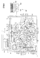
- An immune analyzer 1 is an apparatus for carrying out examinations on various items such as hepatitis B, hepatitis C, tumor marker, and thyroid hormone using specimen such as blood.
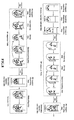
- the immune analyzer 1 is mainly configured by a measurement unit including a specimen conveyance member (sampler) 10, an urgent specimen/chip conveyance member 20, a pipette chip supply device 30, a chip detachment member 40, a specimen dispensing arm 50, reagent installing members 60a and 60b, a cuvette supply member 70, a primary reaction member 80a and a secondary reaction member 80b, reagent dispensing arms 90a, 90b, 90c, and 90d, BF separators 100a and 100b, a conveyance catcher member 110, a detector 120, a waste member 130, a control section 140 (see Fig.
- the disposable pipette chip 2 (see Fig. 5 ) is changed every time suction and discharge of specimen are performed in order to suppress the specimen such as blood suctioned and discharged by the specimen dispensing arm 50 from mixing with other specimen.
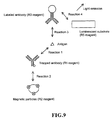
- magnetic particles are bonded to a trapped antibody (R1 reagent) bonded to an antigen contained in a specimen such as blood, which is the measuring object, and thereafter, the bound antigen, the trapped antibody, and the magnetic particles are attracted to a magnet 101b of a BF (Bound Free) separator 100a to remove the R1 reagent containing non-reactive (free) trapped body.
- a labeled antibody (R3 reagent) is bonded to the antigen bound with magnetic particles, and thereafter, the bound magnetic particles, the antigen, and the labeled antibody are attracted to a magnet of a BF separator 100b to remove the R3 reagent containing non-reactive (free) labeled antibody.
- a luminescent substrate that emits light in the reaction process with the labeled antibody is added, and a light emission amount generated through the reaction of the labeled antibody and the luminescent substrate is measured.
- the antigen contained in the specimen that bonds with the labeled antibody is quantitatively measured.
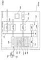
- the control device 400 is configured by a personal computer 401 (PC), and includes a control section 400a, a display member 400b, and a keyboard 400c, as shown in Fig. 1 .
- the control section 400a has a function of performing operation control of each mechanism in the measurement unit, and analyzing optical information of the specimen obtained in the measurement unit.
- the control section 400a consists of CPU, ROM, RAM, and the like.
- the display member 400b is provided to display the analysis result obtained by the control section 400a, and to display graphs etc. of the calibration curve to be hereinafter described.
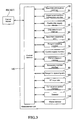
- the control section 400a is mainly configured by a CPU 401a, a ROM 401b, a RAM 401c, a hard disc 401d, a read-out device 401e, an input/output interface 401f, a communication interface 401g, and an image output interface 401h.
- the CPU 401a, the ROM 401b, the RAM 401c, the hard disc 401d, the read-out device 401e, the input/output interface 401f, the communication interface 401g, and the image output interface 401h are connected by a bus 401i.
- the CPU 401a executes computer programs stored in the ROM 401b and the computer programs loaded in the RAM 401c.
- the computer 401 serves as the control device 400 when the CPU 401a executes the application program 404a, as hereinafter described.
- the ROM 401b is configured by mask ROM, PROM, EPROM, EEPROM, and the like, and is recorded with computer programs to be executed by the CPU 401a, data used for the same, and the like.
- the RAM 401c is configured by SRAM, DRAM, and the like.
- the RAM 401c is used to read out the computer programs recorded on the ROM 401b and the hard disc 401d.
- the RAM 401c is used as a work region of the CPU 401a when executing the computer programs.
- the hard disc 401d is installed with various computer programs to be executed by the CPU 401a such as operating system and application program, as well as data used in executing the computer program.
- the application program 404a for providing specifying information to the calibration curve and recycling the calibration curve according to the present embodiment is also installed in the hard disc 401d.
- the read-out device 401e is configured by flexible disc drive, CD-ROM drive, DVD-ROM drive, and the like, and is able to read out computer programs and data recorded on a portable recording medium 404.
- the application program 404a according to the present embodiment is stored in the portable recording medium 404, where the computer 401 reads out the application program 404a from the portable recording medium 404, and installs the application program 404a to the hard disc 401d.
- the application program 404a is not only provided by the portable recording medium 404, but is also provided through communication line (wired or wireless) from external devices communicatably connected with the computer 401 through the communication line.
- the application program 404a may be stored in the hard disc of the server computer on the Internet, so that the computer 401 can access the server computer to download the application program 404a and install the application program 404a to the hard disc 401d.
- Operating system providing graphical user interface environment such as Windows manufactured and sold by US Microsoft Co. is installed in the hard disc 401d.
- the application program 404a according to the present embodiment is assumed to operate on the operating system.
- Calibration curve database 404b for storing calibration curves that can be currently used, recycling calibration curve database 404c for storing calibration curves that have been used in the past, and analysis result database 404d for storing analysis result are stored in the hard disc 401d.
- the configurations of the calibration curve database 404b, the recycling calibration curve database 404c, and the analysis result database 404d will be hereinafter described.
- the input/output interface 401f is configured by serial interface such as USB, IEEE1394, RS-232C; parallel interface such as SCSI, IDE, IEEE1284; analog interface such as D/A converter, A/D converter, and the like.
- the keyboard 400c is connected to the input/output interface 401f, so that the user can input data to the computer 401 using the keyboard 400c.
- the communication interface 401g is, for example, Ethernet (registered trademark) interface.
- the computer 401 transmits and receives data with the measurement unit using a predetermined communication protocol by means of the communication interface 401g.
- the image output interface 401h is connected to the display member 400b configured by LCD, CRT, or the like, and is configured to output an image signal corresponding to the image data provided from the CPU 401a to the display member 400b.
- the display member 400b displays the image (screen) according to the input image signal.
- the specimen conveyance member 10 is configured to convey a rack 4 mounted with a plurality of test tubes 3 accommodating the specimen to a position corresponding to a suction position 1a of the specimen dispensing arm 50.
- the specimen conveyance member 10 includes a rack set section 10a for setting the rack 4 mounted with the test tube 3 accommodating un-processed specimen, and a rack storage section 10b for storing the rack 4 mounted with the test tube 3 accommodating dispense processed specimen.
- test tube 3 accommodating the non-processed specimen is conveyed to the position corresponding to the suction position 1a of the specimen dispensing arm 50, the specimen such as blood in the test tube 3 is suctioned by the specimen dispensing arm 50, and the rack 4 mounted with the relevant test tube 3 is stored in the rack storage section 10b.
- the urgent specimen/chip conveyance member 20 is configured to convey the test tube 3 accommodating urgent specimen that needs to be cut into the specimen being conveyed by the specimen conveyance member 10 for examination to an attachment position 1b of the specimen dispensing arm 50.
- the pipette chip supply device 30 has a function of mounting the placed pipette chip 2 (see Fig. 5 ) on a chip installing section 23b of a conveyance rack 23 of the urgent specimen/chip conveyance member 20 one at a time through a shoot 31.
- the chip detachment member 40 (see Figs. 1 and 2 ) is provided to detach the pipette chip 2 (see Fig. 5 ) attached to the specimen dispensing arm 50 to be hereinafter described.
- the specimen dispensing arm 50 (see Figs. 1 and 2 ) has a function of dispensing the specimen in the test tube 3 conveyed to the suction position 1a by the specimen conveyance member 10 into a cuvette 8 (see Fig. 6 ) held by a holder 81a of a rotatable table 81 of the primary reaction member 80a to be hereinafter described.
- the specimen dispensing arm 50 includes a motor 51, a drive transmitting part 52 connected to the motor 51, and an arm 54 attached to the drive transmitting part 52 by way of a shaft 53.
- the drive transmitting part 52 is configured to turn the arm 54 with the shaft 53 as the center by the driving force from the motor 51, and move the arm in the up and down direction (Z direction).
- a nozzle 54a for suctioning and discharging the specimen is arranged at the distal end of the arm 54.
- the pipette chip 2 (see Fig. 5 ) conveyed by a conveyance rack (not shown) of the urgent specimen/chip conveyance member 20 is attached to the distal end of the nozzle 54a.
- the reagent installing member 60a includes an installing section 61 for installing a reagent container 5 (see Fig. 2 ) accommodating the R1 reagent including trapped antibody and a reagent container 7 (see Fig. 2 ) accommodating the R3 reagent containing labeled antibody; an upper surface 62 arranged on the upper part of the installing section 61 so that foreign substances such as dust does not enter the R1 reagent in the reagent container 5 or the R3 reagent in the reagent container 7 installed in the installing section 61; and a lid 63 attached in an openable/closable manner to the upper surface 62.
- a groove 62a to be inserted with a nozzle 91e of the reagent dispensing arm 90a, to be hereinafter described, and a groove 62b (see Fig. 2 ) to be inserted with a nozzle 93e of the reagent dispensing arm 90c are formed in the upper surface 62.
- the installing section 61 is rotatably configured to convey the installed reagent container 5 and the reagent container 7 to positions corresponding to the groove 62a and the groove 62b of the upper surface 62, respectively.
- the reagent installing member 60b includes an installing section 64 for installing a reagent container 6 (see Fig. 2 ) accommodating the R2 reagent containing magnetic particles; an upper surface 65 arranged on the upper part of the installing section 64 so that foreign substances such as dust does not enter the R2 reagent in the reagent container 6 installed in the installing section 64; and a lid 66 attached in an openable/closable manner to the upper surface 65.
- a groove 65a to be inserted with a nozzle 92e of the reagent dispensing arm 90b, to be hereinafter described is formed in the upper surface 65.
- the installing section 64 is rotatably configured to convey the installed reagent container 6 to a position corresponding to the groove 65a of the upper surface 65.
- the cuvette supply member 70 (see Figs. 1 and 2 ) is configured so as to sequentially supply a plurality of cuvettes 8 (see Fig. 6 ) to the holder 81a of the rotatable table 81 of the primary reaction member 80a.
- the cuvette supply member 70 includes a hopper feeder 71 capable of accommodating the plurality of cuvettes 8, two inductive plates 72 arranged on the lower side of the hopper feeder 71, a supporting board 73 arranged on the lower end of the inductive plate 72, and a supply catcher section 74.
- the supply catcher section 74 has a function of transporting the cuvette 8 (see Fig. 6 ) received by a concave part 73b to the holder 81a of the rotatable table 81 of the primary reaction member 80a.
- the supply catcher section 74 includes a motor 74a, a pulley 74b connected to the motor 74a, a pulley 74c arranged with a predetermined spacing from the pulley 74b, a drive transmission belt 74d attached to the pulley 74b and the pulley 74c, an arm 74e attached to the pulley 74c by way of a shaft, and a drive part 74f for moving the arm 74e in the up and down direction.
- a chuck part 74g for sandwiching and gripping the cuvette 8 is arranged at the distal end of the arm 74e.
- the primary reaction member 80a is arranged to rotatably transport the cuvette 8 held at the holder 81a of the rotatable table 81 by a predetermined angle for every predetermined period (18 seconds in the present embodiment), and to stir the specimen, the R1 reagent, and the R2 reagent in the cuvette 8. That is, the primary reaction member 80a is arranged to react the R2 reagent including magnetic particles and the antigen in the specimen in the cuvette 8.
- the primary reaction member 80a is configured by the rotatable table 81 for conveying the cuvette 8 accommodating the specimen, the R1 reagent, and the R2 reagent in the rotating direction, and a container conveyance section 82 for stirring the specimen, the R1 reagent, and the R2 reagent in the cuvette 8 and conveying the cuvette 8 accommodating the stirred specimen, the R1 reagent, and the R2 reagent to the BF separator 100a (see Figs. 1 and 2 ) to be hereinafter described.
- the container conveyance section 82 is rotatably installed at the center of the rotatable table 81.
- the container conveyance section 82 has a function of gripping the cuvette 8 held at the holder 81a of the rotatable table 81 and stirring the sample in the cuvette 8.
- the container conveyance section 82 also has a function of conveying the cuvette 8 accommodating the sample obtained by stirring and incubating the specimen, the R1 reagent, and the R2 reagent to the BF separator 100a (see Figs. 1 and 2 ).
- the reagent dispensing arm 90a (see Figs. 1 and 2 ) has a function of suctioning the R1 reagent in the reagent container 5 installed in the installing section 61 of the reagent installing member 60a, and dispensing the suctioned R1 reagent into the cuvette 8 dispensed with the specimen of the primary reaction member 80a.
- the reagent dispensing arm 90a includes a motor 91a, a drive transmitting part 91b connected to the motor 91a, and an arm 91d attached to the drive transmitting part 91b by way of a shaft 91c.
- the drive transmitting part 91b is configured to turn the arm 91d with the shaft 91c as the center by the driving force from the motor 91a, and move the arm in the up and down direction.
- a nozzle 91e for suctioning and discharging the R1 reagent in the reagent container 5 is attached to the distal end of the arm 91d. That is, the nozzle 91e is configured to suction the R1 reagent in the reagent container 5 through the groove 62a of the upper surface 62 of the reagent installing member 60a, and thereafter, dispense the suctioned R1 reagent into the cuvette 8 dispensed with the specimen.
- the reagent dispensing arm 90b (see Figs. 1 and 2 ) has a function of dispensing the R2 reagent in the reagent container 6 installed in the installing section 64 of the reagent installing member 60b into the cuvette 8 dispensed with the specimen and the R1 reagent of the primary reaction member 80a.
- the reagent dispensing arm 90b includes a motor 92a, a drive transmitting part 92b connected to the motor 92a, and an arm 92d attached to the drive transmitting part 92b by way of a shaft 92c.
- the drive transmitting part 92b is configured to turn the arm 92d with the shaft 92c as the center by the driving force from the motor 92a, and move the arm in the up and down direction.
- a nozzle 92e for suctioning and discharging the R2 reagent in the reagent container 6 is attached to the distal end of the arm 92d. Therefore, the nozzle 92e is configured to suction the R2 reagent in the reagent container 6 through the groove 65a of the upper surface 65 of the reagent installing member 60b, and thereafter, dispense the suctioned R2 reagent into the cuvette 8 dispensed with the specimen.
- the BF separator 100a (see Figs. 1 and 2 ) is arranged to separate the non-reactive R1 reagent (unnecessary component) and the magnetic particles from the sample in the cuvette 8 (see Fig. 6 ) conveyed by the container conveyance section 82 of the primary reaction member 80a.
- the BF separator 100a includes a magnet collecting section 101 for installing and conveying the cuvette 8 in the rotating direction, a stirring mechanism section 102 for stirring the sample in the cuvette 8, a separation mechanism section 103 for suctioning the sample in the cuvette 8 and discharging washing liquid, and nozzle washing sections 104a and 104b.
- the conveyance catcher member 110 has a function of conveying the cuvette 8 (see Fig. 6 ) of the magnet collecting section 101 of the BF separator 100a in which non-reactive R1 reagent etc. is separated to a holder 83a of a rotatable table 83 of the secondary reaction member 80b.
- the conveyance catcher member 110 includes a motor 110a, a pulley 110b connected to the motor 110a, a pulley 110c arranged with a predetermined spacing from the pulley 110b, a drive transmission belt 110d attached to the pulley 110b and the pulley 110c, an arm 110e attached to the pulley 110c by way of a shaft, and a drive part 110f for moving the arm 110e in the up and down direction.
- a chuck part 110g for sandwiching and gripping the cuvette 8 is arranged at the distal end of the arm 110e.
- the secondary reaction member 80b ( Figs. 1 and 2 ) has a configuration similar to the primary reaction member 80b, and is arranged to rotatably transport the cuvette 8 held at the holder 83a of the rotatable table 83 by a predetermined angle for every predetermined period (18 seconds in the present embodiment), and to stir the specimen, the R1 reagent, the R2 reagent, the R3 reagent, and the R5 reagent in the cuvette 8. That is, the secondary reaction member 80b is arranged to react the R3 reagent including labeled antibody and the antigen in the specimen in the cuvette 8, and to react the R5 reagent having luminescent substrate and the labeled antibody of the R3 reagent.
- the secondary reaction member 80b is configured by the rotatable table 83 for conveying the cuvette 8 accommodating the specimen, the R1 reagent, the R2 reagent, the R3 reagent and the R5 reagent in the rotating direction, and a container conveyance section 84 for stirring the specimen, the R1 reagent, the R2 reagent, the R3 reagent and the R5 reagent in the cuvette 8 and conveying the cuvette 8 accommodating the stirred specimen etc. to the BF separator 100b to be hereinafter described. Furthermore, the container conveyance section 84 has a function of again conveying the cuvette 8 processed by the BF separator 100b to the holder 83a of the rotatable table 83. Detailed configurations of the secondary reaction member 80b are the same as the primary reaction member 80a, and thus the description thereof will be omitted.
- the reagent dispensing arm 90c (see Figs. 1 and 2 ) has a function of suctioning the R3 reagent in the reagent container 7 installed at the installing section 61 of the reagent installing member 60a and dispensing the suctioned R3 reagent into the cuvette 8 dispensed with the specimen, the R1 reagent, and the R2 reagent of the secondary reaction member 80b.
- the reagent dispensing arm 90c includes a motor 93a, a drive transmitting part 93b connected to the motor 93a, and an arm 93d attached to the drive transmitting part 93b by way of a shaft 93c.
- the drive transmitting part 93b is configured to turn the arm 93d with the shaft 93c as the center by the driving force from the motor 93a, and move the arm in the up and down direction.
- a nozzle 93e for suctioning and discharging the R3 reagent in the reagent container 7 is attached to the distal end of the arm 93d. That is, the nozzle 93e is configured to suction the R3 reagent in the reagent container 7 through the groove 62a of the upper surface 62 of the reagent installing member 60a, and thereafter, dispense the suctioned R3 reagent into the cuvette 8 dispensed with the specimen, the R1 reagent, and the R2 reagent.
- the BF separator 100b (see Figs. 1 and 2 ) has a configuration similar to the BF separator 100a, and is arranged to separate the non-reactive R3 reagent (unnecessary component) and the magnetic particles from the sample in the cuvette 8 (see Fig. 7 ) conveyed by the container conveyance section 84 of the secondary reaction member 80b.
- a detailed configuration of the BF separator 100b is the same as the BF separator 100a, and thus the description thereof will be omitted.
- the reagent dispensing arm 90d (see Figs. 1 and 2 ) has a function of dispensing the R5 reagent containing luminescent substrate in the reagent container (not shown) installed at the lower part of the immune analyzer 1 into the cuvette 8 accommodating the specimen, the R1 reagent, the R2 reagent, and the R3 reagent of the secondary reaction member 80b.
- the reagent dispensing arm 90d includes a motor 94a, a drive transmitting part 94b connected to the motor 94a, and an arm 94c attached to the drive transmitting part 93b by way of a shaft.
- the drive transmitting part 94b is configured to turn the arm 94c with the shaft as the center by the driving force from the motor 94a, and move the arm in the up and down direction.
- a tube 94d for discharging the R5 reagent from the reagent container (not shown) installed at the lower part of the immune analyzer 1 into the cuvette 8 held at the holder 83a of the rotatable table 83 is attached to the distal end of the arm 94c.
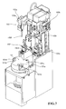
- the detector 120 (see Figs. 1 and 2 ) is arranged to measure the amount of antigen contained in a specimen by acquiring the light generated in the reaction process of the labeled antibody bound to the antigen of the specimen performed with a predetermined process and the luminescent substrate with a photo multiplier tube.
- the detector 120 is configured by an installing section 121 for installing the cuvette 8 accommodating the specimen, the R1 reagent, the R2 reagent, the R3 reagent, and the R5 reagent, and a conveyance mechanism section 122 for conveying the cuvette 8 (see Fig. 6 ) held at the holder 83a of the rotatable table 83 of the secondary reaction member 80b.
- a lid 123 is arranged in an openable/closable manner at the installing section 121 so that external light does not enter the cuvette 8 installed at the installing section 121.
- the waste member 130 (see Figs. 1 and 2 ) is arranged to discard the cuvette 8 (see Fig. 6 ) accommodating the measured sample measured by the detector 120.
- the waste member 130 is configured by a suction part 131 (see Fig. 2 ) for suctioning the measured sample in the cuvette 8 and a discarding hole 132 arranged at a position of a predetermined spacing from the suction part 131. After the measured sample is suctioned by the suction part 131, the used cuvette 8 is discarded to a dust box (not shown) arranged at the lower part of the immune analyzer 1 through the discarding hole 132.
- the cuvette 8 (see Fig. 6 ) is guided from the hopper 71a through the inductive plate 72 to the concave part 73b of the supporting board 73 by driving the motor 71b of the hopper feeder 71 of the cuvette supply member 70.
- the cuvette 8 accommodated in the concave part 73b of the supporting board 73 is conveyed to the holder 81a of the rotatable table 81 of the primary reaction member 80a by the supply catcher section 74.
- the reagent dispensing arm 90a After suctioning the R1 reagent in the reagent container 5 installed in the installing section 61 of the reagent installing member 60a, the reagent dispensing arm 90a is turned towards the primary reaction member 80a side to discharge the suctioned R1 reagent into the cuvette 8 conveyed by the supply catcher section 74. As shown in Figs. 8 and 9 , the R1 reagent contains trapped antibody that binds to the antigen contained in the specimen.
- the specimen dispensing arm 50 suctions the specimen such as blood from the test tube 3 mounted on the rack 4 conveyed to the suction position 1a (see Figs. 1 and 2 ) by the specimen conveyance member 10.
- the specimen dispensing arm 50 is then turned towards the primary reaction member 80a side to discharge the suctioned specimen into the cuvette 8 accommodating the R1 reagent of the holder 81a of the rotatable table 81.
- the container conveyance section 82 of the primary reaction member 80a then stirs the cuvette 8 accommodating the R1 reagent and the specimen.
- the stirred R1 reagent and the specimen are then incubated for a predetermined time in the cuvette 8 of the holder 81a of the rotatable table 81 which rotates by a predetermined angle every 18 seconds. If about 162 seconds (18 seconds x 9) is required for the reaction between the R1 reagent and the specimen, the cuvette 8 accommodating the R1 reagent and the specimen is rotatably transported by 9 pitches after being dispensed with specimen. Thus, the trapped antibody (R1 reagent) and the antigen of the specimen bind while the cuvette 8 is being rotatably transported.
- the reagent dispensing arm 90b After suctioning the R2 reagent in the reagent container 6 installed in the installing section 64 of the reagent installing member 60b, the reagent dispensing arm 90b is turned towards the primary reaction member 80a side to discharge the suctioned R2 reagent into the cuvette 8 accommodating the R1 reagent and the specimen incubated for a predetermined time. As shown in Figs. 8 and 9 , the R2 reagent contains magnetic particles that bind to the trapped antibody bound with the antigen in the specimen.
- the container conveyance section 82 of the primary reaction member 80a then stirs the cuvette 8 accommodating the R1 reagent, the specimen, and the R2 reagent similar to the stirring step of the R1 reagent and the specimen.
- the stirred R1 reagent, the specimen, and the R2 reagent are then incubated for a predetermined time in the cuvette 8 of the holder 81a of the rotatable table 81. If about 90 seconds (18 seconds x 5) is required for the reaction between the trapped antibody (R1 reagent) bound with the antigen of the specimen and the magnetic particles (R2 reagent), the cuvette 8 accommodating the R1 reagent, the specimen, and the R2 reagent is rotatably transported by 5 pitches after being dispensed with the R2 reagent. Thus, the magnetic particles (R2 reagent) and the trapped antibody (R1 reagent) bound with the antigen of the specimen bind while the cuvette 8 is being rotatably transported.
- the cuvette 8 accommodating the incubated R1 reagent, the specimen, and the R2 reagent is conveyed to a cuvette installation hole 101d of the BF separator 100a shown in Fig. 9 by the container conveyance section 82 of the primary reaction member 80a.
- the cuvette 8 installed in the cuvette installation hole 101d of the installing part 101a of the magnet collecting section 101 is transported in the rotating direction with the rotation of the installing part 101a, and arranged at a position corresponding to a primary stirring part 102d of the stirring mechanism section 102.
- the magnetic particles in the cuvette 8 held at the cuvette installation hole 101d of the installing part 101a are collected by a magnet 101b arranged on the side of the cuvette 8.
- the sample in the cuvette 8 is suctioned to remove unnecessary components other than the magnetic particles and the antigen binding with the magnetic particles through the trapped antibody.
- washing liquid is supplied into the cuvette 8 performed with the first washing step in the BF separator 100a, and stirring is performed.
- the unnecessary components caught in the magnetic particles and retained at the inner wall of the cuvette 8 with the magnetic particles then can be dispersed.
- the cuvette 8 stirred in the BF separator 100a is again held at the cuvette installation hole 101d of the magnet collecting section 101 to collect the magnetic particles on the magnet 101b side arranged on the side of the cuvette 8. After collecting the magnetic particles in the cuvette 8, washing liquid and unnecessary components are discharged.
- washing liquid is again supplied into the cuvette 8 performed with the first second washing step in the BF separator 100a, and stirring is performed.
- the cuvette 8 stirred in the BF separator 100a is again held at the cuvette installation hole 101d of the magnet collecting section 101 to collect the magnetic particles on the magnet 101b side arranged on the side of the cuvette 8. After collecting the magnetic particles in the cuvette 8, washing liquid and slightly remaining unnecessary components are reliably discharged.
- the cuvette 8 accommodating the sample, which mainly contains solid-phase magnetic particles removed with unnecessary component, is transported in the rotating direction with the rotation of the installing part 101a of the BF separator 100a and conveyed to the position to be gripped by the chuck part 110g of the conveyance catcher member 110, as shown in Figs. 1 and 2 .
- the cuvette 8 in which separation of the unnecessary components and the magnetic particles is performed by the BF separator 100a is gripped by the chuck part 110g of the conveyance catcher member 110 and conveyed to the holder 83a of the rotatable table 83 of the secondary reaction member 80b, as shown in Figs. 1 and 2 .
- the reagent dispensing arm 90c is turned towards the secondary reaction member 80b side to discharge the suctioned R3 reagent into the cuvette 8 accommodating the magnetic particles (R2 reagent) bound through the trapped antibody (R1 reagent) and the antigen of the specimen.
- the R3 reagent contains labeled antibody that binds to the antigen in the specimen.
- the container conveyance section 84 of the secondary reaction member 80b then stirs the cuvette 8 accommodating the trapped antibody (R1 reagent), the antigen (specimen), the magnetic particles (R2 reagent), and the R3 reagent containing the labeled antibody, similar to the stirring step of the R1 reagent and the specimen described above.
- the stirred trapped antibody (R1 reagent), the antigen (specimen), the magnetic particles (R2 reagent), and the R3 reagent containing the labeled antibody are then incubated for a predetermined time in the cuvette 8 of the holder 83a of the rotatable table 83, as shown in Figs. 1 and 2 .
- the cuvette 8 accommodating the trapped antibody (R1 reagent), the antigen (specimen), the magnetic particles (R2 reagent), and the R3 reagent containing the labeled antibody is rotatably transported by 11 pitches after being dispensed with the R3 reagent.
- the antigen bound with the magnetic particles (R2 reagent) through the trapped antibody (R1 reagent) and the labeled antibody (R3 reagent) bind while the cuvette 8 is being rotatably transported.
- the cuvette 8 accommodating the incubated trapped antibody (R1 reagent), the antigen (specimen), the magnetic particles (R2 reagent), and the R3 reagent containing the labeled antibody is conveyed to the cuvette installation hole 101d of the BF separator 100b by the container conveyance section 84 of the secondary reaction member 80b, similar to the conveying step from the primary reaction member 80a to the BF separator 100a described above.
- the first washing step, four stirring steps, and the second washing step in the BF separator 100a are performed in the BF separator 100b.
- the R3 reagent (unnecessary component) containing the labeled antibody that does not bind with the antigen of the specimen can be sufficiently removed.
- the cuvette 8 accommodating the sample containing the antigen bound with the labeled antibody removed with unnecessary components is transported in the rotating direction with the rotation of the magnet collecting section of the BF separator 100b, and conveyed to a position to which it can be conveyed by the container conveyance section 84 of the secondary reaction member 80b.
- the cuvette 8 in which separation of the unnecessary components and the magnetic particles is performed by the BF separator 100b is again conveyed to the holder 83a of the rotatable table 83 by the container conveyance section 84 of the secondary reaction member 80b as shown in Figs. 1 and 2 .
- the reagent dispensing arm discharges the R4 reagent (dispersion liquid) in the reagent container (not shown) installed at the lower part of the immune analyzer 1 to the cuvette 8 accommodating the trapped antibody (R1 reagent), the magnetic particles (R2 reagent), the labeled antibody (R3 reagent), and the antigen of specimen.
- the container conveyance section 84 of the secondary reaction member 80b then stirs the cuvette 8 accommodating the trapped antibody (R1 reagent), the antigen (specimen), the magnetic particles (R2 reagent), the labeled antibody (R3 reagent), and the R4 reagent, similar to the stirring step of the R1 reagent and the specimen described above.
- the reagent dispensing arm 90d discharges the R5 reagent containing luminescent substrate in the reagent container (not shown) installed at the lower part of the immune analyzer 1 to the cuvette 8 accommodating the trapped antibody (R1 reagent), the magnetic particles (R2 reagent), the labeled antibody (R3 reagent), the dispersion liquid (R4 reagent), and the antigen of specimen through a tube 94d.
- the R5 reagent contains the luminescent substrate that emits light by reacting with the labeled antibody of the R3 reagent.
- the container conveyance section 84 of the secondary reaction member 80b stirs the cuvette 8 accommodating the trapped antibody (R1 reagent), the antigen (specimen), the magnetic particles (R2 reagent), the labeled antibody (R3 reagent), the dispersion liquid (R4 reagent), and the R5 reagent containing the luminescent substrate, similar to the stirring step of the R1 reagent and specimen described above.
- the stirred trapped antibody (R1 reagent), the antigen (specimen), the magnetic particles (R2 reagent), the dispersion liquid (R4 reagent), the labeled antibody, and the R5 reagent containing the luminescent substrate are then incubated for a predetermined time in the cuvette 8 of the holder 83a of the rotatable table 83.
- the cuvette 8 accommodating the trapped antibody (R1 reagent), the antigen (specimen), the magnetic particles (R2 reagent), the labeled antibody (R3 reagent), and the R5 reagent containing the luminescent substrate is rotatably transported by 21 pitches after being dispensed with the R5 reagent.
- the reaction between the labeled antibody (R3 reagent) and the luminescent substrate (R5 reagent) advances while the cuvette 8 is being rotatably transported.
- the cuvette 8 accommodating the incubated trapped antibody (R1 reagent), the antigen (specimen), the magnetic particles (R2 reagent), the labeled antibody (R3 reagent), the dispersion liquid (R4 reagent), and the R5 reagent containing the luminescent substrate is conveyed to the installing section 121 by the conveyance mechanism section 122 of the detector 120.
- the lid 123 is closed to obtain a state in which the interior of the installing section 121 is shielded from the external light, whereby measurement can be performed under the condition the external light is shielded.
- the magnetic particles in the cuvette 8 installed at the installing section 121 is attracted towards the magnet side.
- the measurement of the light emission amount is suppressed from being inhibited by the magnetic particles.
- the light emission amount (amount proportional to the number of photons) generated in the reaction process of the labeled antibody of the R3 reagent and the luminescent substrate of the R5 reagent is acquired with the photo multiplier tube (not shown).
- the cuvette 8 accommodating the measured sample performed with measurement is conveyed to the position below the suction part 131 (see Fig. 2 ) of the waste member 130 by the conveyance mechanism section 122 of the detector 120.
- the suction part 131 of the waste member 130 moves downward, suctions the measured sample, and empties the cuvette 8.
- the conveyance mechanism section 122 of the detector 120 gripping the empty cuvette 8 is turned to be conveyed up to the position corresponding to the discarding hole 132 of the waste member 130, and thereafter, caused to drop the empty cuvette 8 into the discarding hole 132 to discard the used cuvette 8 into the dust box (not shown) arranged at the lower part of the immune analyzer 1 through the discarding hole 132.
- the features of the present embodiment lie in providing an ID number (calibration curve specifying information) specifying the calibration curve to the calibration curve created by the CPU 401a of the control section 400a, and storing the analysis result and the calibration curve specifying information provided to the calibration curve used in the analysis in correspondence to each other.
- ID number calibration curve specifying information
- the calibration curve used in the analysis is specified by the calibration curve specifying information in such manner, and the calibration curve specifying information and the analysis result are stored in correspondence to each other, so that it becomes easy to recognize which calibration curve was used to analyze a certain analysis result, whereby the traceability of the analysis result improves.
- the analysis result using the relevant calibration curve is specified and re-analysis can be easily performed.
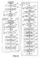
- Fig. 10 is a view showing a flow of creating the calibration curve, providing the calibration curve specifying information to the calibration curve, and registering the calibration curve in the present embodiment.
- step S1 when the user turns on the power (not shown) of the control device 4, initialization (initialization of program) of the control section 4a is executed (step S1), and an initialization screen (not shown) is displayed (step S2).
- step S3 When sampler measurement is selected by the user on the initialization screen (Yes in step S3), the control section 400a displays an order registration screen for sampler measurement shown in Fig. 11 (step S4).
- a calibration curve order input dialogue shown in Fig. 12 is displayed on the display member 400b.
- designation of measurement order for creating the calibration curve such as measurement item name, lot number of reagent, and calibration curve creating method is input by the user (Yes in step S5), and instruction to start measurement is input (Yes in step S6) in this calibration curve order input dialogue, the measurement unit starts the measurement operation according to the specified order (step S7).
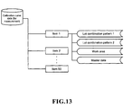
- the control section 400a creates the calibration curve using the measurement data (step S9), and stores the calibration curve in the work area (see Fig. 13 ) of the calibration curve database (step S10).
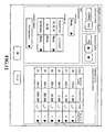
- the calibration curve database has a configuration shown in Fig. 13 , where four types of files are stored for every fifty measurement items. The application of each file is "lot combination pattern 1 (lot 1)", “lot combination pattern 2 (lot 2)", “work area” and "master data”. Among them, "lot combination pattern 1 (lot 1)” and “lot combination pattern 2 (lot 2)” maintain a calibration curve that can be used to calculate concentration.
- R1 to R5 reagents constitute a set
- R4 and R5 reagents constitute a set.
- the reagents are changed in units of sets.
- the old and new reagent sets are not yet completely changed, and the reagent set (old set) scheduled to be changed and the new reagent set coexist in the apparatus.
- two lot combination patterns exist for the reagent set in the apparatus.
- the files of pattern 1 and pattern 2 thus are provided to store the calibration curve corresponding to both combinations.
- the "work area” is a file for temporarily holding data of newly measured calibration curve measurement, data restoring backup file, data reproduced with a recycling function to be hereinafter described, and corrected data, and cannot be used to calculate concentration.
- master data holds data used as a base of one point shift which is a simple measurement method (method of specifying only one coordinate with a calibrator and obtaining the calibration curve graph from the coordinate and the slope of the calibration curve graph obtained in the past on the assumption that the slope of the calibration curve graph is equal to the slope of the calibration curve graph obtained in the past) in time of calibration curve measurement.
- the master data is created by master registering the calibration curve of lot 1, lot 2, or work area. Such master data cannot be used to calculate the concentration.
- the calibration curve screen includes a graph display region 200 for displaying the graph of the calibration curve, and a specifying information display region 201 such as calibration curve ID, which is calibration curve specifying information provided to the relevant calibration curve, and reagent lot.
- calibration curve ID is not provided and the calibration curve ID is not displayed in the specifying information display region 201 of the work area.
- the user can easily check whether or not the calibration curve is appropriate by referencing the graph, and can also check the calibration curve specifying information of the relevant calibration curve by displaying the graph of the calibration curve and the calibration curve specifying information provided to the relevant calibration curve.
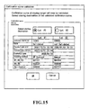
- step S14 when the user instructs validation of the calibration curve data of the work area by clicking "validate” (Yes in step S13), a validation dialogue of the calibration curve shown in Fig. 15 is displayed on the display member 400b (step S14).
- step S15 when the user specifies the copy destination of the calibration curve (Yes in step S15), the control section 400a moves the calibration curve data to the specified lot of lot 1 or lot 2 (step S16).
- the control section updates the lot of the specified destination to "validated” (step S17). Specifically, "validated date and time” is written in the screen ("display target" on the upper part is changed from work area to lot 1 or lot 2) corresponding to the calibration curve screen shown in Fig. 14 , and “validated” is written in place of "not validated” on the right side thereof.
- the control section 400a sets an expiration date of the calibration curve of a predetermined period (e.g., 30 days) from the relevant date, and updates the expiration date of the calibration curve in the calibration curve screen (step S18).
- a predetermined period e.g. 30 days
- the control section 400a After the calibration curve is confirmed, that is, validated, the control section 400a provides the calibration curve ID or the calibration curve specifying information to the calibration curve (step S19), stores the calibration curve ID in the corresponding area (lot 1 or lot 2) of the calibration curve database in correspondence with the calibration curve (step S20), and updates the display to the calibration curve screen displaying the stored calibration curve ID (step S21). Thereafter, a copy of the validated calibration curve is added to the recycling calibration curve database to be hereinafter described (step S22), and the process of providing the calibration curve ID is terminated.
- the measurement data (number of counts of photons) obtained in the measuring step described above is analyzed based on the calibration curve to obtain the concentration (analysis result) of the antigen contained in the specimen.
- the measurement data in the measurement unit is transmitted from the measurement unit to the data processing unit (control device).
- the control device is stored with calibration curve created in advance (created by the CPU 401a of the control section 400a based on the measurement data of when the measurement standard sample which is a mixture of standard sample (calibrator) and reagent is measured by the measurement unit).
- the control section 400a of the control device reads the calibration curve that matches the sample lot of the transmitted measurement data, converts the concentration of the antigen to be measured from the measurement data and the read calibration curve, and stores the result (analysis result).
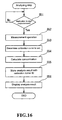
- Fig. 16 is a view showing a flow of the analyzing step in the present embodiment.
- the user operates the keyboard 400c and inputs the instruction to start measurement (Yes in step S51).
- the control section 400a transmits a command to start measurement to the measurement unit, and the measurement operation described above is executed by the measurement unit (step S52).
- the measurement data obtained by measuring the specimen with the measurement unit is transmitted to the control device 400.
- the control section 400a receives the measurement data, and determines the calibration curve to use of the calibration curves stored in lot 1 and lot 2 of the calibration curve database from the lot number of the reagent used in the relevant measurement (step S53).
- the control section 400a then obtains the concentration from the photon count value of the measurement data using the calibration curve (step S54).
- the analysis result obtained in this manner is stored in the analysis result database in correspondence to the calibration curve ID of the used calibration curve (step S55), the analysis result is displayed on the screen (step S56), and the process is terminated.
- the calibration curve used in step S53 may be a calibration curve reproduced through recycling of the calibration curve as hereinafter described.
- the confirmed calibration curve is stored in the calibration curve database for storing a predetermined number of calibration curves used in the analysis, and a copy of the confirmed calibration curve is stored in a recycling calibration curve database.
- the recycling calibration curve database is stored with calibration curve data currently being used as well as the calibration curve data used in the past as shown in Fig. 17 .
- the calibration curves used in the past are stored in the second storage means, designation of a desired calibration curve of the calibration curves stored in the second storage means is accepted by the designation accepting means, and the calibration curve specified by the calibration curve recycling means is stored in the first storage means as a calibration curve that can be used for analysis. Since the calibration curve can be reproduced by the reproducing means for reproducing (recycling) the calibration curve when the calibration curve used in the past for analyzing the measurement data match, the standard sample does not need to be newly measured and the calibration curve does not need to be created. The consumption of the standard sample and the reagent thus can be suppressed, and trouble and time necessary for measuring the standard sample can be reduced.
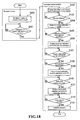
- Fig. 18 is a view showing a flow of recycling the calibration curve used in the past in the present embodiment.
- the browser screen includes an analysis result list table 202 for displaying a list of analysis results.
- the analysis result list table 202 is displayed with the calibration curve ID of the calibration curve used in the analysis and the reagent lot along with the analysis result for every analyzing item.
- the user can then check the calibration curve ID and the reagent lot.
- the user inputs instruction to display the calibration curve screen after checking, and the control section 400a accepts the input (Yes in step S101) and displays the calibration curve screen on the display 400b (step S102).
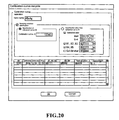
- step S104 When the user selects "calibration curve recycle” from “execute” in the menu bar to select recycling of the calibration curve, such selection is accepted by the control section 400a (Yes in step S103), and a calibration curve recycle dialogue shown in Fig. 20 is displayed. All the calibration curves stored in the recycling calibration curve database described above are displayed on the calibration curve recycle dialogue (step S104).
- step S105 When the calibration curve ID or the reagent lot is specified by the user, such designation is accepted by the control section 400a (Yes in step S105), and the recycling calibration curve that matches the specifying condition is displayed (step S106).
- the user can easily find the desired calibration curve by having the calibration curve stored in the recycling calibration curve database searchable with the calibration curve ID or the calibration curve specifying information, lot number of reagent, created date and time of calibration curve, validated date and time, calibration curve expiration date, lot number of calibrator etc. as the key.
- the calibration curve, calibration curve ID, lot information of reagent used in the measurement of the measurement standard sample, created date and time of calibration curve, validated date and time, calibration curve expiration date, and lot number of calibrator are stored in a correspondence manner in the recycling calibration curve database.
- the target calibration curve can be easily searched from the lot information and the created date and time of the calibration curve, and the like.
- the control section 400a copies the selected recycling calibration curve to the calibration curve database (step S109).
- control section 400a causes the display 400b to display the work area (display recycled calibration curve) (step S111).
- the control section 400a moves the calibration curve of the work area to the specified destination (lot 1 or lot 2) and updates the specified destination to "validated" in step S113, similar to steps S14 to 18 in the flow of calibration curve registration.
- the calibration curve used in the past thereby can be recycled and used in analysis of the measurement data. For instance, if it is known that the difference (difference between lots) in nature between the current reagent and the reagent used in the past is small, the reagent for creating the calibration curve does not need to be consumed because the calibration curve used in the past can be recycled.
- a configuration of storing the analysis result of the immune analyzer and the calibration curve ID used for the analysis in correspondence to each other has been described, but is not limited thereto, and a configuration of providing the calibration curve ID to the calibration curve and storing the analysis result and the calibration curve ID in correspondence to each other in the blood coagulation analyzer of adding the reagent to the sample (blood plasma) and optically measuring the process of coagulation of the sample, for example by measuring absorbance and scattering light of the sample, and converting the measurement data to the concentration of the substance to be measured using the calibration curve obtained by measuring the standard substance in advance may be adopted.
- a configuration of storing the calibration curve used in the past in the recycling calibration curve database, searching for the target calibration curve with the calibration curve ID and the reagent lot number as the key from the recycling calibration curve database when reproducing the calibration curve, and copying the searched calibration curve in the calibration curve database has been described, but is not limited thereto, and a configuration of performing reproduction of the calibration curve by storing the measurement data of the calibrator used in creating the calibration curve used in the past in the recycle database, searching for the target measurement data with the calibration curve ID and the reagent lot number as the key from the recycle database when reproducing the calibration curve, creating the calibration curve using the searched measurement data, and storing the calibration curve in the calibration curve database may be adopted.
- the measurement data of the measurement standard sample, the calibration curve ID, the lot information of the reagent used in measuring the measurement standard sample, the created date and time of the calibration curve, the validated date and time, the calibration curve expiration date, and the lot number etc. of the calibrator may be stored in the recycle database in correspondence to each other.
- the measurement data of the target measurement standard sample can be easily searched from the lot information and the calibration curve created date and time if the lot information of the reagent used in creating the calibration curve to be reproduced, the created date and time of the calibration curve, and the like are known.
Landscapes
- Analytical Chemistry (AREA)
- General Health & Medical Sciences (AREA)
- Physics & Mathematics (AREA)
- Health & Medical Sciences (AREA)
- Life Sciences & Earth Sciences (AREA)
- Chemical & Material Sciences (AREA)
- Quality & Reliability (AREA)
- Biochemistry (AREA)
- Engineering & Computer Science (AREA)
- General Physics & Mathematics (AREA)
- Immunology (AREA)
- Pathology (AREA)
- Automatic Analysis And Handling Materials Therefor (AREA)
- Sampling And Sample Adjustment (AREA)
- Investigating Or Analysing Materials By Optical Means (AREA)
Applications Claiming Priority (1)
| Application Number | Priority Date | Filing Date | Title |
|---|---|---|---|
| JP2007092830A JP4969292B2 (ja) | 2007-03-30 | 2007-03-30 | 試料分析装置 |
Publications (3)
| Publication Number | Publication Date |
|---|---|
| EP1975623A2 true EP1975623A2 (fr) | 2008-10-01 |
| EP1975623A3 EP1975623A3 (fr) | 2017-08-02 |
| EP1975623B1 EP1975623B1 (fr) | 2019-10-30 |
Family
ID=39484006
Family Applications (1)
| Application Number | Title | Priority Date | Filing Date |
|---|---|---|---|
| EP08004572.7A Active EP1975623B1 (fr) | 2007-03-30 | 2008-03-12 | Analyseur d'échantillon |
Country Status (4)
| Country | Link |
|---|---|
| US (1) | US8231830B2 (fr) |
| EP (1) | EP1975623B1 (fr) |
| JP (1) | JP4969292B2 (fr) |
| CN (1) | CN101275960B (fr) |
Cited By (3)
| Publication number | Priority date | Publication date | Assignee | Title |
|---|---|---|---|---|
| EP2813839A1 (fr) * | 2013-06-12 | 2014-12-17 | Roche Diagniostics GmbH | Procédé d'étalonnage de photométrie |
| EP2843418A1 (fr) * | 2013-08-30 | 2015-03-04 | Sysmex Corporation | Analyseur d'échantillon et procédé d'analyse d'échantillon |
| EP3671219A1 (fr) * | 2018-12-18 | 2020-06-24 | F. Hoffmann-La Roche AG | Gestion de l'étalonnage d'un système de diagnostic in vitro |
Families Citing this family (25)
| Publication number | Priority date | Publication date | Assignee | Title |
|---|---|---|---|---|
| US9297820B2 (en) * | 2008-02-13 | 2016-03-29 | Hitachi High-Technologies Corporation | Automatic analyzer |
| EP2282211B1 (fr) * | 2008-05-22 | 2020-07-29 | Hitachi High-Tech Corporation | Analyseur automatique |
| JP5166208B2 (ja) * | 2008-10-28 | 2013-03-21 | シスメックス株式会社 | 検体分析装置、検体分析装置の校正方法及びコンピュータプログラム |
| JP5791954B2 (ja) * | 2011-04-28 | 2015-10-07 | シスメックス株式会社 | 検体分析装置、検体分析システム、測定結果管理装置及びコンピュータプログラム |
| JP5855372B2 (ja) * | 2011-07-07 | 2016-02-09 | シスメックス株式会社 | 検体分析装置及びコンピュータプログラム |
| JP5686710B2 (ja) * | 2011-09-21 | 2015-03-18 | 株式会社日立ハイテクノロジーズ | 自動分析装置 |
| JP5830331B2 (ja) * | 2011-09-28 | 2015-12-09 | シスメックス株式会社 | 試料分析装置および試料分析装置の制御方法 |
| JP5924950B2 (ja) * | 2012-01-20 | 2016-05-25 | シスメックス株式会社 | 試料分析装置 |
| CN103364458A (zh) * | 2012-04-01 | 2013-10-23 | 郡是株式会社 | 计测显示装置 |
| US9435718B2 (en) | 2012-10-22 | 2016-09-06 | Qiagen Gaithersburg, Inc. | Automated pelletized sample decanting apparatus and methods |
| US9310281B2 (en) | 2012-10-22 | 2016-04-12 | Qiagen Gaithersburg, Inc. | Automated pelletized sample blotting apparatus and methods |
| US9260763B2 (en) | 2012-10-22 | 2016-02-16 | Qiagen Gaithersburg, Inc. | Sample processing method using tube strips and tube strip holder |
| WO2015160420A1 (fr) * | 2014-04-14 | 2015-10-22 | Becton, Dickinson And Company | Système et procédé d'étalonnage de réactif |
| US9835640B2 (en) | 2015-02-13 | 2017-12-05 | Abbott Laboratories | Automated storage modules for diagnostic analyzer liquids and related systems and methods |
| US10895579B2 (en) * | 2015-03-02 | 2021-01-19 | Hitachi High-Tech Corporation | Automatic analyzer |
| CN104880567B (zh) * | 2015-05-29 | 2018-04-27 | 深圳市清时捷科技有限公司 | 一种分析仪器的显示方法和分析仪器 |
| US12003902B2 (en) * | 2015-06-15 | 2024-06-04 | Sentronic Gmbh Gesellschaft Fur Optische Messsysteme | System and method for transmitting information |
| US10876953B2 (en) | 2015-07-15 | 2020-12-29 | Becton, Dickinson And Company | System and method for label selection |
| JP6858008B2 (ja) | 2016-11-30 | 2021-04-14 | シスメックス株式会社 | 粒子分散装置及び粒子分散方法 |
| WO2019156828A1 (fr) * | 2018-02-06 | 2019-08-15 | Siemens Healthcare Diagnostics Inc. | Appareil et procédés prédictifs de contrôle d'inventaire |
| US11060968B2 (en) * | 2018-03-30 | 2021-07-13 | International Business Machines Corporation | Mobile chemical analysis |
| CN111912974B (zh) * | 2019-05-09 | 2022-02-18 | 深圳市帝迈生物技术有限公司 | 一种免疫试剂定标方法 |
| CN110606228B (zh) * | 2019-10-08 | 2024-08-20 | 百思达智能科技(惠州)有限公司 | 一种用于器皿灌装的自动化设备 |
| JP7488728B2 (ja) | 2020-08-31 | 2024-05-22 | シスメックス株式会社 | 検量線設定方法、検量線設定プログラムおよび検体分析装置 |
| CN114047328B (zh) * | 2022-01-10 | 2022-06-21 | 深圳市帝迈生物技术有限公司 | 一种样本分析仪及其检测方法 |
Citations (1)
| Publication number | Priority date | Publication date | Assignee | Title |
|---|---|---|---|---|
| JP2003315343A (ja) | 2002-04-24 | 2003-11-06 | Olympus Optical Co Ltd | 自動分析装置及びネットワークシステム |
Family Cites Families (27)
| Publication number | Priority date | Publication date | Assignee | Title |
|---|---|---|---|---|
| JPH0776771B2 (ja) * | 1984-07-30 | 1995-08-16 | 株式会社東芝 | 自動化学分析装置 |
| JPH01227063A (ja) * | 1988-03-07 | 1989-09-11 | Maikuronikusu Kk | 液体分析用前処理装置 |
| JP2654682B2 (ja) * | 1989-02-17 | 1997-09-17 | 富士写真フイルム株式会社 | 生化学分析装置、生化学分析補正方法及び補正値記録体 |
| JPH0483160A (ja) * | 1990-07-26 | 1992-03-17 | Shimadzu Corp | Toc計 |
| JPH08101208A (ja) * | 1994-09-30 | 1996-04-16 | Shimadzu Corp | 自動化学分析装置 |
| US5786223A (en) * | 1995-05-19 | 1998-07-28 | Fuji Photo Film Co., Ltd. | Two-step calibration method for dry chemical analysis element |
| JP3728861B2 (ja) * | 1997-04-10 | 2005-12-21 | 株式会社日立製作所 | 自動分析装置 |
| JP3704416B2 (ja) * | 1997-04-23 | 2005-10-12 | 株式会社日立製作所 | 自動分析装置 |
| JP2000162214A (ja) * | 1998-11-30 | 2000-06-16 | Toshiba Corp | 自動分析装置 |
| US6277584B1 (en) * | 1998-12-16 | 2001-08-21 | Dade Behring Inc. | Method for calibrating a chemical analyzer with improved accuracy at low signal levels |
| JP4091194B2 (ja) * | 1999-02-03 | 2008-05-28 | 株式会社東芝 | 自動分析装置およびそれに用いる分析結果処理方法 |
| CN1317394C (zh) | 2000-06-12 | 2007-05-23 | 希森美康株式会社 | 免疫测定方法和免疫测定装置 |
| EP1291659A3 (fr) * | 2001-09-06 | 2008-05-21 | Sysmex Corporation | Appareil d'analyse automatique et ses composants |
| JP2003083982A (ja) * | 2001-09-12 | 2003-03-19 | Olympus Optical Co Ltd | 分析装置 |
| US6998247B2 (en) * | 2002-03-08 | 2006-02-14 | Sensys Medical, Inc. | Method and apparatus using alternative site glucose determinations to calibrate and maintain noninvasive and implantable analyzers |
| JP4117181B2 (ja) * | 2002-11-21 | 2008-07-16 | 株式会社日立ハイテクノロジーズ | 自動分析装置 |
| JP4045999B2 (ja) * | 2003-04-11 | 2008-02-13 | 株式会社島津製作所 | 機器分析用データ管理装置 |
| JP4098174B2 (ja) * | 2003-07-16 | 2008-06-11 | シスメックス株式会社 | 分析装置 |
| JP4805564B2 (ja) * | 2004-10-22 | 2011-11-02 | シスメックス株式会社 | 生体試料分析装置および方法 |
| US9243993B2 (en) * | 2005-03-17 | 2016-01-26 | Sysmex Corporation | Sample analyzer and sample analyzing method |
| JP4576307B2 (ja) * | 2005-09-12 | 2010-11-04 | 株式会社日立ハイテクノロジーズ | 自動分析装置 |
| JP4755874B2 (ja) * | 2005-09-27 | 2011-08-24 | シスメックス株式会社 | 検体分析装置、検体分析用処理コンピュータ、検体分析装置における操作用画面の表示方法、及び検体分析装置用処理コンピュータのためのコンピュータプログラム |
| JP4768409B2 (ja) * | 2005-11-15 | 2011-09-07 | シスメックス株式会社 | 試料分析装置、試料分析本体装置、及び試料容器供給装置 |
| JP2008058123A (ja) * | 2006-08-31 | 2008-03-13 | Hitachi High-Technologies Corp | 自動分析装置 |
| EP1953526B1 (fr) * | 2007-02-01 | 2017-08-30 | Sysmex Corporation | Analyseur hématologique, procédé d'analyse de liquide organique et produit de programme informatique |
| JP5032150B2 (ja) * | 2007-02-22 | 2012-09-26 | シスメックス株式会社 | 試料処理装置 |
| JP5162177B2 (ja) * | 2007-07-31 | 2013-03-13 | シスメックス株式会社 | 粒子分析装置及び粒子分析方法 |
-
2007
- 2007-03-30 JP JP2007092830A patent/JP4969292B2/ja active Active
-
2008
- 2008-03-12 EP EP08004572.7A patent/EP1975623B1/fr active Active
- 2008-03-18 US US12/050,791 patent/US8231830B2/en active Active
- 2008-03-28 CN CN2008100848886A patent/CN101275960B/zh active Active
Patent Citations (1)
| Publication number | Priority date | Publication date | Assignee | Title |
|---|---|---|---|---|
| JP2003315343A (ja) | 2002-04-24 | 2003-11-06 | Olympus Optical Co Ltd | 自動分析装置及びネットワークシステム |
Cited By (6)
| Publication number | Priority date | Publication date | Assignee | Title |
|---|---|---|---|---|
| EP2813839A1 (fr) * | 2013-06-12 | 2014-12-17 | Roche Diagniostics GmbH | Procédé d'étalonnage de photométrie |
| WO2014198716A1 (fr) * | 2013-06-12 | 2014-12-18 | F.Hoffmann-La Roche Ag | Procede d'etalonnage pour photometrie |
| US9952234B2 (en) | 2013-06-12 | 2018-04-24 | Roche Diagnostics Operations, Inc. | Calibration method for photometry |
| EP2843418A1 (fr) * | 2013-08-30 | 2015-03-04 | Sysmex Corporation | Analyseur d'échantillon et procédé d'analyse d'échantillon |
| US9500662B2 (en) | 2013-08-30 | 2016-11-22 | Sysmex Corporation | Sample analyzer and sample analyzing method |
| EP3671219A1 (fr) * | 2018-12-18 | 2020-06-24 | F. Hoffmann-La Roche AG | Gestion de l'étalonnage d'un système de diagnostic in vitro |
Also Published As
| Publication number | Publication date |
|---|---|
| CN101275960B (zh) | 2012-08-22 |
| US20080240988A1 (en) | 2008-10-02 |
| JP2008249576A (ja) | 2008-10-16 |
| JP4969292B2 (ja) | 2012-07-04 |
| EP1975623B1 (fr) | 2019-10-30 |
| US8231830B2 (en) | 2012-07-31 |
| CN101275960A (zh) | 2008-10-01 |
| EP1975623A3 (fr) | 2017-08-02 |
Similar Documents
| Publication | Publication Date | Title |
|---|---|---|
| EP1975623B1 (fr) | Analyseur d'échantillon | |
| EP2040080B1 (fr) | Analyseur d'échantillons et procédé d'analyse d'échantillons | |
| CN101393226B (zh) | 标本分析仪及故障信息显示方法 | |
| US8535607B2 (en) | Sample analyzer | |
| US8333123B2 (en) | Sample processing apparatus and sample information display apparatus | |
| US8778268B2 (en) | Specimen analyzer, abnormality control method of the same and computer program product | |
| US6579717B1 (en) | Specific solution handling method for calibration and quality control by automatic analytical apparatus | |
| JP5339853B2 (ja) | 検体処理システム | |
| JP5179890B2 (ja) | 試料分析装置 | |
| EP2028494A2 (fr) | Analyseur d'échantillon et procédé d'analyse d'échantillon | |
| US8279715B2 (en) | Sample analyzing apparatus | |
| JP5171182B2 (ja) | 検体分析装置 | |
| JP5727219B2 (ja) | 検体分析装置及び検体分析システム | |
| JP4567767B2 (ja) | 試料収容容器に対する自動マーキング方法。 | |
| JP5670129B2 (ja) | 検体処理装置および検体処理方法 | |
| CN101493386B (zh) | 试样处理装置及处理结果的输出方法和分析仪的控制系统 | |
| CN103217536A (zh) | 试样分析装置及试样分析方法 | |
| JP2009244177A (ja) | 分析装置、分析方法、及びコンピュータプログラム | |
| JP5108366B2 (ja) | 検体分析装置 | |
| JP4191533B2 (ja) | 試料分析装置および方法 | |
| JP5484107B2 (ja) | 検体処理システム |
Legal Events
| Date | Code | Title | Description |
|---|---|---|---|
| PUAI | Public reference made under article 153(3) epc to a published international application that has entered the european phase |
Free format text: ORIGINAL CODE: 0009012 |
|
| AK | Designated contracting states |
Kind code of ref document: A2 Designated state(s): AT BE BG CH CY CZ DE DK EE ES FI FR GB GR HR HU IE IS IT LI LT LU LV MC MT NL NO PL PT RO SE SI SK TR |
|
| AX | Request for extension of the european patent |
Extension state: AL BA MK RS |
|
| PUAL | Search report despatched |
Free format text: ORIGINAL CODE: 0009013 |
|
| AK | Designated contracting states |
Kind code of ref document: A3 Designated state(s): AT BE BG CH CY CZ DE DK EE ES FI FR GB GR HR HU IE IS IT LI LT LU LV MC MT NL NO PL PT RO SE SI SK TR |
|
| AX | Request for extension of the european patent |
Extension state: AL BA MK RS |
|
| RIC1 | Information provided on ipc code assigned before grant |
Ipc: G01N 35/00 20060101AFI20170628BHEP |
|
| STAA | Information on the status of an ep patent application or granted ep patent |
Free format text: STATUS: REQUEST FOR EXAMINATION WAS MADE |
|
| 17P | Request for examination filed |
Effective date: 20180129 |
|
| RBV | Designated contracting states (corrected) |
Designated state(s): AT BE BG CH CY CZ DE DK EE ES FI FR GB GR HR HU IE IS IT LI LT LU LV MC MT NL NO PL PT RO SE SI SK TR |
|
| AKX | Designation fees paid |
Designated state(s): AT BE BG CH CY CZ DE DK EE ES FI FR GB GR HR HU IE IS IT LI LT LU LV MC MT NL NO PL PT RO SE SI SK TR |
|
| AXX | Extension fees paid |
Extension state: RS Extension state: BA Extension state: MK Extension state: AL |
|
| GRAP | Despatch of communication of intention to grant a patent |
Free format text: ORIGINAL CODE: EPIDOSNIGR1 |
|
| STAA | Information on the status of an ep patent application or granted ep patent |
Free format text: STATUS: GRANT OF PATENT IS INTENDED |
|
| INTG | Intention to grant announced |
Effective date: 20190521 |
|
| GRAS | Grant fee paid |
Free format text: ORIGINAL CODE: EPIDOSNIGR3 |
|
| GRAA | (expected) grant |
Free format text: ORIGINAL CODE: 0009210 |
|
| STAA | Information on the status of an ep patent application or granted ep patent |
Free format text: STATUS: THE PATENT HAS BEEN GRANTED |
|
| AK | Designated contracting states |
Kind code of ref document: B1 Designated state(s): AT BE BG CH CY CZ DE DK EE ES FI FR GB GR HR HU IE IS IT LI LT LU LV MC MT NL NO PL PT RO SE SI SK TR |
|
| REG | Reference to a national code |
Ref country code: GB Ref legal event code: FG4D |
|
| REG | Reference to a national code |
Ref country code: CH Ref legal event code: EP |
|
| REG | Reference to a national code |
Ref country code: DE Ref legal event code: R096 Ref document number: 602008061516 Country of ref document: DE |
|
| REG | Reference to a national code |
Ref country code: AT Ref legal event code: REF Ref document number: 1196719 Country of ref document: AT Kind code of ref document: T Effective date: 20191115 |
|
| REG | Reference to a national code |
Ref country code: IE Ref legal event code: FG4D |
|
| REG | Reference to a national code |
Ref country code: LT Ref legal event code: MG4D |
|
| PG25 | Lapsed in a contracting state [announced via postgrant information from national office to epo] |
Ref country code: LT Free format text: LAPSE BECAUSE OF FAILURE TO SUBMIT A TRANSLATION OF THE DESCRIPTION OR TO PAY THE FEE WITHIN THE PRESCRIBED TIME-LIMIT Effective date: 20191030 Ref country code: GR Free format text: LAPSE BECAUSE OF FAILURE TO SUBMIT A TRANSLATION OF THE DESCRIPTION OR TO PAY THE FEE WITHIN THE PRESCRIBED TIME-LIMIT Effective date: 20200131 Ref country code: NO Free format text: LAPSE BECAUSE OF FAILURE TO SUBMIT A TRANSLATION OF THE DESCRIPTION OR TO PAY THE FEE WITHIN THE PRESCRIBED TIME-LIMIT Effective date: 20200130 Ref country code: PL Free format text: LAPSE BECAUSE OF FAILURE TO SUBMIT A TRANSLATION OF THE DESCRIPTION OR TO PAY THE FEE WITHIN THE PRESCRIBED TIME-LIMIT Effective date: 20191030 Ref country code: ES Free format text: LAPSE BECAUSE OF FAILURE TO SUBMIT A TRANSLATION OF THE DESCRIPTION OR TO PAY THE FEE WITHIN THE PRESCRIBED TIME-LIMIT Effective date: 20191030 Ref country code: NL Free format text: LAPSE BECAUSE OF FAILURE TO SUBMIT A TRANSLATION OF THE DESCRIPTION OR TO PAY THE FEE WITHIN THE PRESCRIBED TIME-LIMIT Effective date: 20191030 Ref country code: PT Free format text: LAPSE BECAUSE OF FAILURE TO SUBMIT A TRANSLATION OF THE DESCRIPTION OR TO PAY THE FEE WITHIN THE PRESCRIBED TIME-LIMIT Effective date: 20200302 Ref country code: LV Free format text: LAPSE BECAUSE OF FAILURE TO SUBMIT A TRANSLATION OF THE DESCRIPTION OR TO PAY THE FEE WITHIN THE PRESCRIBED TIME-LIMIT Effective date: 20191030 Ref country code: SE Free format text: LAPSE BECAUSE OF FAILURE TO SUBMIT A TRANSLATION OF THE DESCRIPTION OR TO PAY THE FEE WITHIN THE PRESCRIBED TIME-LIMIT Effective date: 20191030 Ref country code: FI Free format text: LAPSE BECAUSE OF FAILURE TO SUBMIT A TRANSLATION OF THE DESCRIPTION OR TO PAY THE FEE WITHIN THE PRESCRIBED TIME-LIMIT Effective date: 20191030 Ref country code: BG Free format text: LAPSE BECAUSE OF FAILURE TO SUBMIT A TRANSLATION OF THE DESCRIPTION OR TO PAY THE FEE WITHIN THE PRESCRIBED TIME-LIMIT Effective date: 20200130 |
|
| REG | Reference to a national code |
Ref country code: NL Ref legal event code: MP Effective date: 20191030 |
|
| PG25 | Lapsed in a contracting state [announced via postgrant information from national office to epo] |
Ref country code: IS Free format text: LAPSE BECAUSE OF FAILURE TO SUBMIT A TRANSLATION OF THE DESCRIPTION OR TO PAY THE FEE WITHIN THE PRESCRIBED TIME-LIMIT Effective date: 20200229 Ref country code: HR Free format text: LAPSE BECAUSE OF FAILURE TO SUBMIT A TRANSLATION OF THE DESCRIPTION OR TO PAY THE FEE WITHIN THE PRESCRIBED TIME-LIMIT Effective date: 20191030 |
|
| PG25 | Lapsed in a contracting state [announced via postgrant information from national office to epo] |
Ref country code: EE Free format text: LAPSE BECAUSE OF FAILURE TO SUBMIT A TRANSLATION OF THE DESCRIPTION OR TO PAY THE FEE WITHIN THE PRESCRIBED TIME-LIMIT Effective date: 20191030 Ref country code: DK Free format text: LAPSE BECAUSE OF FAILURE TO SUBMIT A TRANSLATION OF THE DESCRIPTION OR TO PAY THE FEE WITHIN THE PRESCRIBED TIME-LIMIT Effective date: 20191030 Ref country code: RO Free format text: LAPSE BECAUSE OF FAILURE TO SUBMIT A TRANSLATION OF THE DESCRIPTION OR TO PAY THE FEE WITHIN THE PRESCRIBED TIME-LIMIT Effective date: 20191030 Ref country code: CZ Free format text: LAPSE BECAUSE OF FAILURE TO SUBMIT A TRANSLATION OF THE DESCRIPTION OR TO PAY THE FEE WITHIN THE PRESCRIBED TIME-LIMIT Effective date: 20191030 |
|
| REG | Reference to a national code |
Ref country code: DE Ref legal event code: R097 Ref document number: 602008061516 Country of ref document: DE |
|
| REG | Reference to a national code |
Ref country code: AT Ref legal event code: MK05 Ref document number: 1196719 Country of ref document: AT Kind code of ref document: T Effective date: 20191030 |
|
| PG25 | Lapsed in a contracting state [announced via postgrant information from national office to epo] |
Ref country code: SK Free format text: LAPSE BECAUSE OF FAILURE TO SUBMIT A TRANSLATION OF THE DESCRIPTION OR TO PAY THE FEE WITHIN THE PRESCRIBED TIME-LIMIT Effective date: 20191030 Ref country code: IT Free format text: LAPSE BECAUSE OF FAILURE TO SUBMIT A TRANSLATION OF THE DESCRIPTION OR TO PAY THE FEE WITHIN THE PRESCRIBED TIME-LIMIT Effective date: 20191030 |
|
| PLBE | No opposition filed within time limit |
Free format text: ORIGINAL CODE: 0009261 |
|
| STAA | Information on the status of an ep patent application or granted ep patent |
Free format text: STATUS: NO OPPOSITION FILED WITHIN TIME LIMIT |
|
| 26N | No opposition filed |
Effective date: 20200731 |
|
| PG25 | Lapsed in a contracting state [announced via postgrant information from national office to epo] |
Ref country code: MC Free format text: LAPSE BECAUSE OF FAILURE TO SUBMIT A TRANSLATION OF THE DESCRIPTION OR TO PAY THE FEE WITHIN THE PRESCRIBED TIME-LIMIT Effective date: 20191030 |
|
| REG | Reference to a national code |
Ref country code: CH Ref legal event code: PL |
|
| PG25 | Lapsed in a contracting state [announced via postgrant information from national office to epo] |
Ref country code: AT Free format text: LAPSE BECAUSE OF FAILURE TO SUBMIT A TRANSLATION OF THE DESCRIPTION OR TO PAY THE FEE WITHIN THE PRESCRIBED TIME-LIMIT Effective date: 20191030 Ref country code: SI Free format text: LAPSE BECAUSE OF FAILURE TO SUBMIT A TRANSLATION OF THE DESCRIPTION OR TO PAY THE FEE WITHIN THE PRESCRIBED TIME-LIMIT Effective date: 20191030 |
|
| REG | Reference to a national code |
Ref country code: BE Ref legal event code: MM Effective date: 20200331 |
|
| PG25 | Lapsed in a contracting state [announced via postgrant information from national office to epo] |
Ref country code: LU Free format text: LAPSE BECAUSE OF NON-PAYMENT OF DUE FEES Effective date: 20200312 |
|
| PG25 | Lapsed in a contracting state [announced via postgrant information from national office to epo] |
Ref country code: CH Free format text: LAPSE BECAUSE OF NON-PAYMENT OF DUE FEES Effective date: 20200331 Ref country code: IE Free format text: LAPSE BECAUSE OF NON-PAYMENT OF DUE FEES Effective date: 20200312 Ref country code: LI Free format text: LAPSE BECAUSE OF NON-PAYMENT OF DUE FEES Effective date: 20200331 |
|
| PG25 | Lapsed in a contracting state [announced via postgrant information from national office to epo] |
Ref country code: BE Free format text: LAPSE BECAUSE OF NON-PAYMENT OF DUE FEES Effective date: 20200331 |
|
| PG25 | Lapsed in a contracting state [announced via postgrant information from national office to epo] |
Ref country code: TR Free format text: LAPSE BECAUSE OF FAILURE TO SUBMIT A TRANSLATION OF THE DESCRIPTION OR TO PAY THE FEE WITHIN THE PRESCRIBED TIME-LIMIT Effective date: 20191030 Ref country code: MT Free format text: LAPSE BECAUSE OF FAILURE TO SUBMIT A TRANSLATION OF THE DESCRIPTION OR TO PAY THE FEE WITHIN THE PRESCRIBED TIME-LIMIT Effective date: 20191030 Ref country code: CY Free format text: LAPSE BECAUSE OF FAILURE TO SUBMIT A TRANSLATION OF THE DESCRIPTION OR TO PAY THE FEE WITHIN THE PRESCRIBED TIME-LIMIT Effective date: 20191030 |
|
| PGFP | Annual fee paid to national office [announced via postgrant information from national office to epo] |
Ref country code: DE Payment date: 20240130 Year of fee payment: 17 Ref country code: GB Payment date: 20240201 Year of fee payment: 17 |
|
| PGFP | Annual fee paid to national office [announced via postgrant information from national office to epo] |
Ref country code: FR Payment date: 20240213 Year of fee payment: 17 |