EP1972786A2 - Compresseur rotatif, système de climatisation de véhicule et chauffe-eau comprenant le compresseur - Google Patents
Compresseur rotatif, système de climatisation de véhicule et chauffe-eau comprenant le compresseur Download PDFInfo
- Publication number
- EP1972786A2 EP1972786A2 EP08011548A EP08011548A EP1972786A2 EP 1972786 A2 EP1972786 A2 EP 1972786A2 EP 08011548 A EP08011548 A EP 08011548A EP 08011548 A EP08011548 A EP 08011548A EP 1972786 A2 EP1972786 A2 EP 1972786A2
- Authority
- EP
- European Patent Office
- Prior art keywords
- compression element
- airtight container
- refrigerant
- pressure
- cylinder
- Prior art date
- Legal status (The legal status is an assumption and is not a legal conclusion. Google has not performed a legal analysis and makes no representation as to the accuracy of the status listed.)
- Granted
Links
Images


Classifications
-
- F—MECHANICAL ENGINEERING; LIGHTING; HEATING; WEAPONS; BLASTING
- F04—POSITIVE - DISPLACEMENT MACHINES FOR LIQUIDS; PUMPS FOR LIQUIDS OR ELASTIC FLUIDS
- F04C—ROTARY-PISTON, OR OSCILLATING-PISTON, POSITIVE-DISPLACEMENT MACHINES FOR LIQUIDS; ROTARY-PISTON, OR OSCILLATING-PISTON, POSITIVE-DISPLACEMENT PUMPS
- F04C18/00—Rotary-piston pumps specially adapted for elastic fluids
- F04C18/30—Rotary-piston pumps specially adapted for elastic fluids having the characteristics covered by two or more of groups F04C18/02, F04C18/08, F04C18/22, F04C18/24, F04C18/48, or having the characteristics covered by one of these groups together with some other type of movement between co-operating members
- F04C18/34—Rotary-piston pumps specially adapted for elastic fluids having the characteristics covered by two or more of groups F04C18/02, F04C18/08, F04C18/22, F04C18/24, F04C18/48, or having the characteristics covered by one of these groups together with some other type of movement between co-operating members having the movement defined in group F04C18/08 or F04C18/22 and relative reciprocation between the co-operating members
- F04C18/356—Rotary-piston pumps specially adapted for elastic fluids having the characteristics covered by two or more of groups F04C18/02, F04C18/08, F04C18/22, F04C18/24, F04C18/48, or having the characteristics covered by one of these groups together with some other type of movement between co-operating members having the movement defined in group F04C18/08 or F04C18/22 and relative reciprocation between the co-operating members with vanes reciprocating with respect to the outer member
- F04C18/3562—Rotary-piston pumps specially adapted for elastic fluids having the characteristics covered by two or more of groups F04C18/02, F04C18/08, F04C18/22, F04C18/24, F04C18/48, or having the characteristics covered by one of these groups together with some other type of movement between co-operating members having the movement defined in group F04C18/08 or F04C18/22 and relative reciprocation between the co-operating members with vanes reciprocating with respect to the outer member the inner and outer member being in contact along one line or continuous surfaces substantially parallel to the axis of rotation
- F04C18/3564—Rotary-piston pumps specially adapted for elastic fluids having the characteristics covered by two or more of groups F04C18/02, F04C18/08, F04C18/22, F04C18/24, F04C18/48, or having the characteristics covered by one of these groups together with some other type of movement between co-operating members having the movement defined in group F04C18/08 or F04C18/22 and relative reciprocation between the co-operating members with vanes reciprocating with respect to the outer member the inner and outer member being in contact along one line or continuous surfaces substantially parallel to the axis of rotation the surfaces of the inner and outer member, forming the working space, being surfaces of revolution
-
- F—MECHANICAL ENGINEERING; LIGHTING; HEATING; WEAPONS; BLASTING
- F04—POSITIVE - DISPLACEMENT MACHINES FOR LIQUIDS; PUMPS FOR LIQUIDS OR ELASTIC FLUIDS
- F04C—ROTARY-PISTON, OR OSCILLATING-PISTON, POSITIVE-DISPLACEMENT MACHINES FOR LIQUIDS; ROTARY-PISTON, OR OSCILLATING-PISTON, POSITIVE-DISPLACEMENT PUMPS
- F04C23/00—Combinations of two or more pumps, each being of rotary-piston or oscillating-piston type, specially adapted for elastic fluids; Pumping installations specially adapted for elastic fluids; Multi-stage pumps specially adapted for elastic fluids
- F04C23/001—Combinations of two or more pumps, each being of rotary-piston or oscillating-piston type, specially adapted for elastic fluids; Pumping installations specially adapted for elastic fluids; Multi-stage pumps specially adapted for elastic fluids of similar working principle
-
- F—MECHANICAL ENGINEERING; LIGHTING; HEATING; WEAPONS; BLASTING
- F04—POSITIVE - DISPLACEMENT MACHINES FOR LIQUIDS; PUMPS FOR LIQUIDS OR ELASTIC FLUIDS
- F04C—ROTARY-PISTON, OR OSCILLATING-PISTON, POSITIVE-DISPLACEMENT MACHINES FOR LIQUIDS; ROTARY-PISTON, OR OSCILLATING-PISTON, POSITIVE-DISPLACEMENT PUMPS
- F04C23/00—Combinations of two or more pumps, each being of rotary-piston or oscillating-piston type, specially adapted for elastic fluids; Pumping installations specially adapted for elastic fluids; Multi-stage pumps specially adapted for elastic fluids
- F04C23/008—Hermetic pumps
-
- F—MECHANICAL ENGINEERING; LIGHTING; HEATING; WEAPONS; BLASTING
- F04—POSITIVE - DISPLACEMENT MACHINES FOR LIQUIDS; PUMPS FOR LIQUIDS OR ELASTIC FLUIDS
- F04C—ROTARY-PISTON, OR OSCILLATING-PISTON, POSITIVE-DISPLACEMENT MACHINES FOR LIQUIDS; ROTARY-PISTON, OR OSCILLATING-PISTON, POSITIVE-DISPLACEMENT PUMPS
- F04C2210/00—Fluid
- F04C2210/10—Fluid working
- F04C2210/1027—CO2
-
- F—MECHANICAL ENGINEERING; LIGHTING; HEATING; WEAPONS; BLASTING
- F04—POSITIVE - DISPLACEMENT MACHINES FOR LIQUIDS; PUMPS FOR LIQUIDS OR ELASTIC FLUIDS
- F04C—ROTARY-PISTON, OR OSCILLATING-PISTON, POSITIVE-DISPLACEMENT MACHINES FOR LIQUIDS; ROTARY-PISTON, OR OSCILLATING-PISTON, POSITIVE-DISPLACEMENT PUMPS
- F04C2210/00—Fluid
- F04C2210/10—Fluid working
- F04C2210/1072—Oxygen (O2)
-
- F—MECHANICAL ENGINEERING; LIGHTING; HEATING; WEAPONS; BLASTING
- F25—REFRIGERATION OR COOLING; COMBINED HEATING AND REFRIGERATION SYSTEMS; HEAT PUMP SYSTEMS; MANUFACTURE OR STORAGE OF ICE; LIQUEFACTION SOLIDIFICATION OF GASES
- F25B—REFRIGERATION MACHINES, PLANTS OR SYSTEMS; COMBINED HEATING AND REFRIGERATION SYSTEMS; HEAT PUMP SYSTEMS
- F25B2400/00—General features or devices for refrigeration machines, plants or systems, combined heating and refrigeration systems or heat-pump systems, i.e. not limited to a particular subgroup of F25B
- F25B2400/02—Centrifugal separation of gas, liquid or oil
-
- Y—GENERAL TAGGING OF NEW TECHNOLOGICAL DEVELOPMENTS; GENERAL TAGGING OF CROSS-SECTIONAL TECHNOLOGIES SPANNING OVER SEVERAL SECTIONS OF THE IPC; TECHNICAL SUBJECTS COVERED BY FORMER USPC CROSS-REFERENCE ART COLLECTIONS [XRACs] AND DIGESTS
- Y10—TECHNICAL SUBJECTS COVERED BY FORMER USPC
- Y10S—TECHNICAL SUBJECTS COVERED BY FORMER USPC CROSS-REFERENCE ART COLLECTIONS [XRACs] AND DIGESTS
- Y10S418/00—Rotary expansible chamber devices
- Y10S418/01—Non-working fluid separation
Definitions
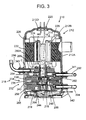
- the electromotive element 14 is disposed above the upper cover 66 in the airtight container 12 at a predetermined interval.
- a peripheral portion of the upper cover 66 is fixed to the upper support member 54 from above via main bolts 78... Tips of the main bolts 78... engage with the lower support member 56.
- a refrigerant introducing tube 92 for introducing the refrigerant gas into the upper cylinder 38 is inserted/connected into the sleeve 141, and one end of the refrigerant introducing tube 92 communicates with a suction passage (not shown) of the upper cylinder 38.
- the refrigerant introducing tube 92 passes through an upper part of the airtight container 12 to reach the sleeve 144, and the other end thereof is inserted/connected into the sleeve 144 to communicate with the inside of the airtight container 12.
- the lower end of the space portion 102 has a substantially conical shape gradually thinned toward the fine hole 108, and the lower end of the fine hole 108 opens toward the oil reservoir 13 formed in the bottom part of the airtight container 12.
- the oil separation mechanism 100 is disposed in the airtight container 12 of the rotary compressor 10, the refrigerant circuit including the compressor 10 can be prevented from being enlarged, and this can contribute to miniaturization of an apparatus.
- a refrigerant introducing tube 294 for introducing the refrigerant gas into the lower cylinder 240 is inserted/connected into the sleeve 342, and one end of the refrigerant introducing tube 294 communicates with the suction passage 258 of the cylinder 240.
- upper and lower support members 425, 445 which are support members for blocking an upper opening surface of the upper cylinder 421 and a lower opening surface of the lower cylinder 441 and for serving also as bearings of the rotation shaft 404.
- a discharge valve 430 of the second stage compression element 420 for opening/closing the discharge port 429 is disposed in an upper part of the upper support member 425 in a state in which the valve is positioned in the discharge noise silencing chamber 427.
- the lower cover 448 is constituted of a donut-shaped circular steel plate, and fixed to the lower support member 445 from below by main bolts 465 in a peripheral portion thereof. It is to be noted that tips of the main bolts 465 engage with the upper support member 425.
- a low-pressure (LP) refrigerant drawn in the compression chamber 441a of the lower cylinder 441 on the low pressure chamber side is compressed by the operation of the lower roller 443 and the lower vane 444 to obtain an intermediate pressure (MP), and discharged into the discharge noise silencing chamber 447 formed in the lower support member 445 from the lower cylinder 441 on the high pressure chamber side via the discharge port 449.
- MP intermediate pressure
- the gas refrigerant having the intermediate pressure discharged into the discharge noise silencing chamber 447 is discharged into the airtight container 402 from the intermediate discharge tube 466 via a communication path (not shown), and accordingly the inside of the airtight container 402 obtains the intermediate pressure.
- the discharged refrigerant in the second stage compression element 420 is circulated in a refrigerant circuit (not shown) disposed outside the two-stage compression system rotary compressor 401 from the discharge noise silencing chamber 427 formed in the upper support member 425 via the discharge piping 432, and drawn in a first stage compression element 440 side again.
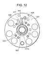
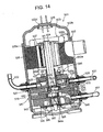
- the rotary compression mechanism section 510 is constituted of a high stage side compression element 520 and a low stage side compression element 540 which are driven by the rotation shaft 504 of the electric motor 503.
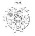
- the high stage side compression element 520 and the low stage side compression element 540 are constituted of: an intermediate partition plate 560; upper and lower cylinders 521, 541 disposed on/under the intermediate partition plate 560; upper and lower eccentric portions 522, 542 disposed on the rotation shaft 504 with a phase difference of 180 degrees in the upper and lower cylinders 521, 541; upper and lower rollers 523, 543 (see FIGS. 17 , 18 ) fitted into the upper and lower eccentric portions 522, 542 to eccentrically rotate; upper and lower vanes 524, 544 (see FIGS.
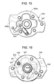
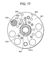
- suction passages 526a, 546a which connect suction ports 526, 546 (see FIGS. 17 , 18 ) to the insides of the upper and lower cylinders 521, 541, respectively, and dented discharge noise silencing chambers 527, 547.
- the discharge noise silencing chambers 527, 547 communicate with discharge ports 529, 549. Openings of these discharge noise silencing chambers 527, 547 are closed by covers, respectively. That is, the discharge noise silencing chamber 527 is closed by an upper cover 528, and the discharge noise silencing chamber 547 is closed by a lower cover 548.
- the refrigerant in a refrigerant circuit connected to the outside is drawn in a compression chamber 541a of the lower cylinder 541 on the low pressure chamber side via the suction piping 551, and the suction passage 546a formed in the lower support member 545 and further via a suction port 546 shown in a lower surface view of the lower cylinder 541 in FIG. 17 .
Applications Claiming Priority (5)
| Application Number | Priority Date | Filing Date | Title |
|---|---|---|---|
| JP2003342461A JP2005105986A (ja) | 2003-09-30 | 2003-09-30 | 縦型ロータリコンプレッサ |
| JP2003352566A JP2005113878A (ja) | 2003-10-10 | 2003-10-10 | ロータリーコンプレッサ |
| JP2003376064A JP4289975B2 (ja) | 2003-11-05 | 2003-11-05 | 多段圧縮式ロータリ圧縮機 |
| JP2003387349A JP2005147562A (ja) | 2003-11-18 | 2003-11-18 | 2段圧縮式ロータリ圧縮機並びにこれを用いたカーエアコン及びヒートポンプ式給湯装置 |
| EP04021471A EP1520990B1 (fr) | 2003-09-30 | 2004-09-09 | Compresseur rotatif |
Related Parent Applications (2)
| Application Number | Title | Priority Date | Filing Date |
|---|---|---|---|
| EP04021471.0 Division | 2004-09-09 | ||
| EP04021471A Division EP1520990B1 (fr) | 2003-09-30 | 2004-09-09 | Compresseur rotatif |
Publications (3)
| Publication Number | Publication Date |
|---|---|
| EP1972786A2 true EP1972786A2 (fr) | 2008-09-24 |
| EP1972786A3 EP1972786A3 (fr) | 2009-06-10 |
| EP1972786B1 EP1972786B1 (fr) | 2010-08-18 |
Family
ID=34317604
Family Applications (3)
| Application Number | Title | Priority Date | Filing Date |
|---|---|---|---|
| EP08011547A Not-in-force EP1972787B1 (fr) | 2003-09-30 | 2004-09-09 | Compresseur rotatif avec silencieux |
| EP04021471A Not-in-force EP1520990B1 (fr) | 2003-09-30 | 2004-09-09 | Compresseur rotatif |
| EP08011548A Not-in-force EP1972786B1 (fr) | 2003-09-30 | 2004-09-09 | Compresseur rotatif, système de climatisation de véhicule et chauffe-eau comprenant le compresseur |
Family Applications Before (2)
| Application Number | Title | Priority Date | Filing Date |
|---|---|---|---|
| EP08011547A Not-in-force EP1972787B1 (fr) | 2003-09-30 | 2004-09-09 | Compresseur rotatif avec silencieux |
| EP04021471A Not-in-force EP1520990B1 (fr) | 2003-09-30 | 2004-09-09 | Compresseur rotatif |
Country Status (5)
| Country | Link |
|---|---|
| US (1) | US7462021B2 (fr) |
| EP (3) | EP1972787B1 (fr) |
| CN (2) | CN100430603C (fr) |
| AT (3) | ATE472059T1 (fr) |
| DE (2) | DE602004028767D1 (fr) |
Families Citing this family (29)
| Publication number | Priority date | Publication date | Assignee | Title |
|---|---|---|---|---|
| US8353681B2 (en) * | 2004-08-24 | 2013-01-15 | Luk Fahrzeug-Hydraulik Gmbh & Co. Kg | Compressor having a drive mechanism and a lubricant separator |
| US20060245961A1 (en) * | 2005-04-28 | 2006-11-02 | Tecumseh Products Company | Rotary compressor with permanent magnet motor |
| CN100402872C (zh) * | 2005-07-21 | 2008-07-16 | 李玉斌 | 一种用于三汽缸旋转式压缩机的曲轴 |
| US7543456B2 (en) * | 2006-06-30 | 2009-06-09 | Airgenerate Llc | Heat pump liquid heater |
| US20090159259A1 (en) * | 2006-06-30 | 2009-06-25 | Sunil Kumar Sinha | Modular heat pump liquid heater system |
| DE102006058839A1 (de) * | 2006-12-13 | 2008-06-19 | Pfeiffer Vacuum Gmbh | Schmiermittelgedichtete Drehschiebervakuumpumpe |
| DE102008013784B4 (de) * | 2007-03-15 | 2017-03-23 | Denso Corporation | Kompressor |
| JP4251239B2 (ja) * | 2007-07-25 | 2009-04-08 | ダイキン工業株式会社 | 密閉式圧縮機 |
| CN102459910B (zh) | 2009-06-16 | 2015-03-11 | 大金工业株式会社 | 回转式压缩机 |
| JP5150564B2 (ja) * | 2009-06-22 | 2013-02-20 | 日立アプライアンス株式会社 | 横置型密閉式圧縮機 |
| JP5515990B2 (ja) | 2010-04-06 | 2014-06-11 | 株式会社Ihi | ターボ圧縮機及びターボ冷凍機 |
| EP2612035A2 (fr) | 2010-08-30 | 2013-07-10 | Oscomp Systems Inc. | Compresseur à refroidissement par injection de liquide |
| US9267504B2 (en) | 2010-08-30 | 2016-02-23 | Hicor Technologies, Inc. | Compressor with liquid injection cooling |
| CN102812251B (zh) | 2011-03-18 | 2015-06-10 | 松下电器产业株式会社 | 压缩机 |
| EP2687726B1 (fr) * | 2011-03-18 | 2014-11-05 | Panasonic Corporation | Compresseur |
| CN103089628B (zh) * | 2011-11-07 | 2016-03-16 | 三洋电机株式会社 | 旋转压缩机 |
| CN103089627B (zh) * | 2011-11-07 | 2015-08-12 | 三洋电机株式会社 | 旋转压缩机 |
| JP6090169B2 (ja) * | 2011-11-10 | 2017-03-08 | パナソニックIpマネジメント株式会社 | 圧縮機 |
| CN103797249B (zh) * | 2011-11-10 | 2016-08-24 | 松下电器产业株式会社 | 压缩机 |
| WO2013172002A1 (fr) * | 2012-05-14 | 2013-11-21 | パナソニック株式会社 | Compresseur |
| JP6077352B2 (ja) * | 2013-03-26 | 2017-02-08 | 東芝キヤリア株式会社 | 多気筒回転式圧縮機及び冷凍サイクル装置 |
| CN103821723B (zh) * | 2014-02-17 | 2016-12-07 | 广东美芝制冷设备有限公司 | 旋转式压缩机及具有其的制冷循环装置 |
| CN105134596B (zh) * | 2014-06-04 | 2019-05-31 | 珠海格力节能环保制冷技术研究中心有限公司 | 多级压缩机 |
| BE1022091B1 (nl) * | 2014-08-14 | 2016-02-15 | Atlas Copco Airpower Naamloze Vennootschap | Spiraalcompressor |
| JP6643712B2 (ja) * | 2016-02-26 | 2020-02-12 | パナソニックIpマネジメント株式会社 | 2シリンダ型密閉圧縮機 |
| CN110914607B (zh) * | 2017-07-25 | 2021-06-08 | 三菱电机株式会社 | 制冷循环装置 |
| CN208831238U (zh) * | 2017-12-22 | 2019-05-07 | 珠海格力节能环保制冷技术研究中心有限公司 | 一种压缩机及制冷循环装置 |
| CN112746963B (zh) * | 2019-10-31 | 2022-06-14 | 广东美的白色家电技术创新中心有限公司 | 压缩机、压缩机组件、热交换系统及电器设备 |
| JP6897811B1 (ja) * | 2020-01-30 | 2021-07-07 | 株式会社富士通ゼネラル | ロータリ圧縮機 |
Citations (5)
| Publication number | Priority date | Publication date | Assignee | Title |
|---|---|---|---|---|
| JPH02294587A (ja) | 1989-05-09 | 1990-12-05 | Matsushita Electric Ind Co Ltd | 2段圧縮型回転圧縮機 |
| JPH10141270A (ja) | 1996-11-01 | 1998-05-26 | Matsushita Electric Ind Co Ltd | 2段気体圧縮機 |
| JP2000105004A (ja) | 1998-09-28 | 2000-04-11 | Sanyo Electric Co Ltd | 回転式圧縮機 |
| JP2000105005A (ja) | 1998-09-29 | 2000-04-11 | Sanyo Electric Co Ltd | 回転式圧縮機 |
| JP2003074997A (ja) | 2001-09-04 | 2003-03-12 | Sanyo Electric Co Ltd | 超臨界冷凍装置 |
Family Cites Families (18)
| Publication number | Priority date | Publication date | Assignee | Title |
|---|---|---|---|---|
| US3250459A (en) * | 1964-06-15 | 1966-05-10 | Ingersoll Rand Co | Gear-rotor motor-compressor |
| US3558248A (en) * | 1968-01-10 | 1971-01-26 | Lennox Ind Inc | Screw type refrigerant compressor |
| JPS59110884A (ja) * | 1982-12-17 | 1984-06-26 | Hitachi Ltd | スクロ−ル圧縮機 |
| US4640669A (en) * | 1984-11-13 | 1987-02-03 | Tecumseh Products Company | Rotary compressor lubrication arrangement |
| JPS62203992A (ja) * | 1986-03-03 | 1987-09-08 | Hitachi Ltd | 密閉形スクロ−ル圧縮機 |
| JPS63138189A (ja) * | 1986-11-29 | 1988-06-10 | Toshiba Corp | 回転式圧縮機 |
| JPH0826865B2 (ja) * | 1986-12-25 | 1996-03-21 | 株式会社東芝 | 2シリンダロータリ圧縮機 |
| GB2259332B (en) * | 1991-06-19 | 1994-12-14 | Brasil Compressores Sa | Hermetic compressor with rotary rolling piston |
| JP2803456B2 (ja) * | 1991-10-23 | 1998-09-24 | 三菱電機株式会社 | 多気筒回転式圧縮機 |
| JPH0626484A (ja) * | 1992-07-10 | 1994-02-01 | Daikin Ind Ltd | 高圧ドーム形電動圧縮機 |
| JPH0960591A (ja) * | 1995-08-21 | 1997-03-04 | Toyota Autom Loom Works Ltd | 圧縮機のオイル分離機構 |
| JP3671552B2 (ja) * | 1996-09-30 | 2005-07-13 | ダイキン工業株式会社 | 圧縮機用油分離器およびその製造方法 |
| JP4103225B2 (ja) * | 1998-06-24 | 2008-06-18 | 株式会社日本自動車部品総合研究所 | 圧縮機 |
| JP2001073945A (ja) * | 1999-08-31 | 2001-03-21 | Sanyo Electric Co Ltd | 密閉型電動圧縮機 |
| US6309198B1 (en) * | 2000-02-24 | 2001-10-30 | Scroll Technologies | Scroll compressor with improved oil flow |
| JP3370046B2 (ja) * | 2000-03-30 | 2003-01-27 | 三洋電機株式会社 | 多段圧縮機 |
| US6499971B2 (en) * | 2000-12-01 | 2002-12-31 | Bristol Compressors, Inc. | Compressor utilizing shell with low pressure side motor and high pressure side oil sump |
| CN1423055A (zh) * | 2001-11-30 | 2003-06-11 | 三洋电机株式会社 | 回转压缩机、其制造方法、及使用该压缩机的除霜装置 |
-
2004
- 2004-09-09 EP EP08011547A patent/EP1972787B1/fr not_active Not-in-force
- 2004-09-09 EP EP04021471A patent/EP1520990B1/fr not_active Not-in-force
- 2004-09-09 AT AT04021471T patent/ATE472059T1/de not_active IP Right Cessation
- 2004-09-09 AT AT08011547T patent/ATE529641T1/de not_active IP Right Cessation
- 2004-09-09 AT AT08011548T patent/ATE478261T1/de not_active IP Right Cessation
- 2004-09-09 DE DE602004028767T patent/DE602004028767D1/de active Active
- 2004-09-09 EP EP08011548A patent/EP1972786B1/fr not_active Not-in-force
- 2004-09-09 DE DE602004027781T patent/DE602004027781D1/de active Active
- 2004-09-22 US US10/945,925 patent/US7462021B2/en not_active Expired - Fee Related
- 2004-09-30 CN CNB2004100921582A patent/CN100430603C/zh not_active Expired - Fee Related
- 2004-09-30 CN CN2007101696960A patent/CN101201050B/zh not_active Expired - Fee Related
Patent Citations (6)
| Publication number | Priority date | Publication date | Assignee | Title |
|---|---|---|---|---|
| JPH02294587A (ja) | 1989-05-09 | 1990-12-05 | Matsushita Electric Ind Co Ltd | 2段圧縮型回転圧縮機 |
| JP2507047B2 (ja) | 1989-05-09 | 1996-06-12 | 松下電器産業株式会社 | 2段圧縮型回転圧縮機 |
| JPH10141270A (ja) | 1996-11-01 | 1998-05-26 | Matsushita Electric Ind Co Ltd | 2段気体圧縮機 |
| JP2000105004A (ja) | 1998-09-28 | 2000-04-11 | Sanyo Electric Co Ltd | 回転式圧縮機 |
| JP2000105005A (ja) | 1998-09-29 | 2000-04-11 | Sanyo Electric Co Ltd | 回転式圧縮機 |
| JP2003074997A (ja) | 2001-09-04 | 2003-03-12 | Sanyo Electric Co Ltd | 超臨界冷凍装置 |
Also Published As
| Publication number | Publication date |
|---|---|
| ATE472059T1 (de) | 2010-07-15 |
| US7462021B2 (en) | 2008-12-09 |
| US20050069423A1 (en) | 2005-03-31 |
| EP1972786A3 (fr) | 2009-06-10 |
| EP1520990A3 (fr) | 2006-01-11 |
| CN101201050A (zh) | 2008-06-18 |
| EP1520990B1 (fr) | 2010-06-23 |
| CN100430603C (zh) | 2008-11-05 |
| DE602004027781D1 (de) | 2010-08-05 |
| EP1520990A2 (fr) | 2005-04-06 |
| CN101201050B (zh) | 2010-06-09 |
| ATE529641T1 (de) | 2011-11-15 |
| EP1972787A3 (fr) | 2009-06-10 |
| DE602004028767D1 (de) | 2010-09-30 |
| CN1603625A (zh) | 2005-04-06 |
| EP1972787A2 (fr) | 2008-09-24 |
| ATE478261T1 (de) | 2010-09-15 |
| EP1972786B1 (fr) | 2010-08-18 |
| EP1972787B1 (fr) | 2011-10-19 |
Similar Documents
| Publication | Publication Date | Title |
|---|---|---|
| EP1972786B1 (fr) | Compresseur rotatif, système de climatisation de véhicule et chauffe-eau comprenant le compresseur | |
| US8998596B2 (en) | Scroll compressor | |
| KR20100010451A (ko) | 압축기 | |
| EP2312164B1 (fr) | Compresseur à volutes | |
| WO2006014081A1 (fr) | Dispositif à cylindrée variable pour compresseur rotatif et méthode d’utilisation d’un climatiseur s’y rattachant | |
| EP2187060B1 (fr) | Compresseur hermétique et dispositif de cycle de réfrigération en disposant | |
| KR101381085B1 (ko) | 로터리식 2단 압축기 | |
| KR102565824B1 (ko) | 스크롤 압축기 | |
| US20060104846A1 (en) | Scroll compressor | |
| EP4067657A2 (fr) | Compresseur à spirale et climatiseur le comprenant | |
| US11692547B2 (en) | Hermetic compressor having oil guide that surrounds rotating shaft | |
| EP3636929B1 (fr) | Compresseur rotatif | |
| EP1911975B1 (fr) | Compresseur électrique scellé | |
| JP4766872B2 (ja) | 多気筒回転圧縮機 | |
| CN112177933A (zh) | 压缩机 | |
| CN112412789B (zh) | 压缩机及冷冻循环装置 | |
| KR102566589B1 (ko) | 스크롤형 압축기 | |
| WO2023074214A1 (fr) | Compresseur et dispositif de congélateur | |
| JP4263047B2 (ja) | 横置き型圧縮機 | |
| JP4169620B2 (ja) | 冷媒サイクル装置 | |
| KR100360862B1 (ko) | 로터리 압축기의 토출 밸브 장치 | |
| CN116457574A (zh) | 压缩机以及制冷循环装置 | |
| CN112412791A (zh) | 回转式压缩机及冷冻循环装置 | |
| JP2000205131A (ja) | 密閉型電動圧縮機 |
Legal Events
| Date | Code | Title | Description |
|---|---|---|---|
| PUAI | Public reference made under article 153(3) epc to a published international application that has entered the european phase |
Free format text: ORIGINAL CODE: 0009012 |
|
| AC | Divisional application: reference to earlier application |
Ref document number: 1520990 Country of ref document: EP Kind code of ref document: P |
|
| AK | Designated contracting states |
Kind code of ref document: A2 Designated state(s): AT BE BG CH CY CZ DE DK EE ES FI FR GB GR HU IE IT LI LU MC NL PL PT RO SE SI SK TR |
|
| RIN1 | Information on inventor provided before grant (corrected) |
Inventor name: MATSUURA, DAI Inventor name: EBARA, TOSHIYUKI Inventor name: MATSUMORI, HIROYUKI Inventor name: SAITO, TAKAYASU Inventor name: SATO, TAKASHI |
|
| PUAL | Search report despatched |
Free format text: ORIGINAL CODE: 0009013 |
|
| AK | Designated contracting states |
Kind code of ref document: A3 Designated state(s): AT BE BG CH CY CZ DE DK EE ES FI FR GB GR HU IE IT LI LU MC NL PL PT RO SE SI SK TR |
|
| RIC1 | Information provided on ipc code assigned before grant |
Ipc: F04C 29/06 20060101ALI20090505BHEP Ipc: F04C 23/00 20060101ALI20090505BHEP Ipc: F04C 29/02 20060101AFI20090505BHEP Ipc: F04C 18/356 20060101ALI20090505BHEP |
|
| 17P | Request for examination filed |
Effective date: 20091208 |
|
| GRAP | Despatch of communication of intention to grant a patent |
Free format text: ORIGINAL CODE: EPIDOSNIGR1 |
|
| AKX | Designation fees paid |
Designated state(s): AT BE BG CH CY CZ DE DK EE ES FI FR GB GR HU IE IT LI LU MC NL PL PT RO SE SI SK TR |
|
| RIN1 | Information on inventor provided before grant (corrected) |
Inventor name: MATSUMORI, HIROYUKI Inventor name: EBARA, TOSHIYUKI Inventor name: SAITO, TAKAYASU Inventor name: MATSUURA, DAI Inventor name: SATO, TAKASHI |
|
| GRAS | Grant fee paid |
Free format text: ORIGINAL CODE: EPIDOSNIGR3 |
|
| GRAA | (expected) grant |
Free format text: ORIGINAL CODE: 0009210 |
|
| AC | Divisional application: reference to earlier application |
Ref document number: 1520990 Country of ref document: EP Kind code of ref document: P |
|
| AK | Designated contracting states |
Kind code of ref document: B1 Designated state(s): AT BE BG CH CY CZ DE DK EE ES FI FR GB GR HU IE IT LI LU MC NL PL PT RO SE SI SK TR |
|
| REG | Reference to a national code |
Ref country code: GB Ref legal event code: FG4D |
|
| REG | Reference to a national code |
Ref country code: CH Ref legal event code: EP |
|
| REG | Reference to a national code |
Ref country code: IE Ref legal event code: FG4D |
|
| REF | Corresponds to: |
Ref document number: 602004028767 Country of ref document: DE Date of ref document: 20100930 Kind code of ref document: P |
|
| REG | Reference to a national code |
Ref country code: NL Ref legal event code: VDEP Effective date: 20100818 |
|
| PG25 | Lapsed in a contracting state [announced via postgrant information from national office to epo] |
Ref country code: AT Free format text: LAPSE BECAUSE OF FAILURE TO SUBMIT A TRANSLATION OF THE DESCRIPTION OR TO PAY THE FEE WITHIN THE PRESCRIBED TIME-LIMIT Effective date: 20100818 Ref country code: FI Free format text: LAPSE BECAUSE OF FAILURE TO SUBMIT A TRANSLATION OF THE DESCRIPTION OR TO PAY THE FEE WITHIN THE PRESCRIBED TIME-LIMIT Effective date: 20100818 |
|
| PG25 | Lapsed in a contracting state [announced via postgrant information from national office to epo] |
Ref country code: CY Free format text: LAPSE BECAUSE OF FAILURE TO SUBMIT A TRANSLATION OF THE DESCRIPTION OR TO PAY THE FEE WITHIN THE PRESCRIBED TIME-LIMIT Effective date: 20100818 Ref country code: BG Free format text: LAPSE BECAUSE OF FAILURE TO SUBMIT A TRANSLATION OF THE DESCRIPTION OR TO PAY THE FEE WITHIN THE PRESCRIBED TIME-LIMIT Effective date: 20101118 Ref country code: PL Free format text: LAPSE BECAUSE OF FAILURE TO SUBMIT A TRANSLATION OF THE DESCRIPTION OR TO PAY THE FEE WITHIN THE PRESCRIBED TIME-LIMIT Effective date: 20100818 Ref country code: PT Free format text: LAPSE BECAUSE OF FAILURE TO SUBMIT A TRANSLATION OF THE DESCRIPTION OR TO PAY THE FEE WITHIN THE PRESCRIBED TIME-LIMIT Effective date: 20101220 Ref country code: SI Free format text: LAPSE BECAUSE OF FAILURE TO SUBMIT A TRANSLATION OF THE DESCRIPTION OR TO PAY THE FEE WITHIN THE PRESCRIBED TIME-LIMIT Effective date: 20100818 |
|
| PG25 | Lapsed in a contracting state [announced via postgrant information from national office to epo] |
Ref country code: GR Free format text: LAPSE BECAUSE OF FAILURE TO SUBMIT A TRANSLATION OF THE DESCRIPTION OR TO PAY THE FEE WITHIN THE PRESCRIBED TIME-LIMIT Effective date: 20101119 Ref country code: BE Free format text: LAPSE BECAUSE OF FAILURE TO SUBMIT A TRANSLATION OF THE DESCRIPTION OR TO PAY THE FEE WITHIN THE PRESCRIBED TIME-LIMIT Effective date: 20100818 Ref country code: NL Free format text: LAPSE BECAUSE OF FAILURE TO SUBMIT A TRANSLATION OF THE DESCRIPTION OR TO PAY THE FEE WITHIN THE PRESCRIBED TIME-LIMIT Effective date: 20100818 Ref country code: SE Free format text: LAPSE BECAUSE OF FAILURE TO SUBMIT A TRANSLATION OF THE DESCRIPTION OR TO PAY THE FEE WITHIN THE PRESCRIBED TIME-LIMIT Effective date: 20100818 |
|
| PG25 | Lapsed in a contracting state [announced via postgrant information from national office to epo] |
Ref country code: DK Free format text: LAPSE BECAUSE OF FAILURE TO SUBMIT A TRANSLATION OF THE DESCRIPTION OR TO PAY THE FEE WITHIN THE PRESCRIBED TIME-LIMIT Effective date: 20100818 Ref country code: MC Free format text: LAPSE BECAUSE OF NON-PAYMENT OF DUE FEES Effective date: 20100930 |
|
| REG | Reference to a national code |
Ref country code: CH Ref legal event code: PL |
|
| PG25 | Lapsed in a contracting state [announced via postgrant information from national office to epo] |
Ref country code: RO Free format text: LAPSE BECAUSE OF FAILURE TO SUBMIT A TRANSLATION OF THE DESCRIPTION OR TO PAY THE FEE WITHIN THE PRESCRIBED TIME-LIMIT Effective date: 20100818 Ref country code: EE Free format text: LAPSE BECAUSE OF FAILURE TO SUBMIT A TRANSLATION OF THE DESCRIPTION OR TO PAY THE FEE WITHIN THE PRESCRIBED TIME-LIMIT Effective date: 20100818 Ref country code: IT Free format text: LAPSE BECAUSE OF FAILURE TO SUBMIT A TRANSLATION OF THE DESCRIPTION OR TO PAY THE FEE WITHIN THE PRESCRIBED TIME-LIMIT Effective date: 20100818 Ref country code: SK Free format text: LAPSE BECAUSE OF FAILURE TO SUBMIT A TRANSLATION OF THE DESCRIPTION OR TO PAY THE FEE WITHIN THE PRESCRIBED TIME-LIMIT Effective date: 20100818 Ref country code: CZ Free format text: LAPSE BECAUSE OF FAILURE TO SUBMIT A TRANSLATION OF THE DESCRIPTION OR TO PAY THE FEE WITHIN THE PRESCRIBED TIME-LIMIT Effective date: 20100818 |
|
| PLBE | No opposition filed within time limit |
Free format text: ORIGINAL CODE: 0009261 |
|
| STAA | Information on the status of an ep patent application or granted ep patent |
Free format text: STATUS: NO OPPOSITION FILED WITHIN TIME LIMIT |
|
| PG25 | Lapsed in a contracting state [announced via postgrant information from national office to epo] |
Ref country code: ES Free format text: LAPSE BECAUSE OF FAILURE TO SUBMIT A TRANSLATION OF THE DESCRIPTION OR TO PAY THE FEE WITHIN THE PRESCRIBED TIME-LIMIT Effective date: 20101129 |
|
| 26N | No opposition filed |
Effective date: 20110519 |
|
| PG25 | Lapsed in a contracting state [announced via postgrant information from national office to epo] |
Ref country code: LI Free format text: LAPSE BECAUSE OF NON-PAYMENT OF DUE FEES Effective date: 20100930 Ref country code: CH Free format text: LAPSE BECAUSE OF NON-PAYMENT OF DUE FEES Effective date: 20100930 Ref country code: IE Free format text: LAPSE BECAUSE OF NON-PAYMENT OF DUE FEES Effective date: 20100909 |
|
| REG | Reference to a national code |
Ref country code: DE Ref legal event code: R097 Ref document number: 602004028767 Country of ref document: DE Effective date: 20110519 |
|
| PG25 | Lapsed in a contracting state [announced via postgrant information from national office to epo] |
Ref country code: LU Free format text: LAPSE BECAUSE OF NON-PAYMENT OF DUE FEES Effective date: 20100909 Ref country code: HU Free format text: LAPSE BECAUSE OF FAILURE TO SUBMIT A TRANSLATION OF THE DESCRIPTION OR TO PAY THE FEE WITHIN THE PRESCRIBED TIME-LIMIT Effective date: 20110219 |
|
| PG25 | Lapsed in a contracting state [announced via postgrant information from national office to epo] |
Ref country code: TR Free format text: LAPSE BECAUSE OF FAILURE TO SUBMIT A TRANSLATION OF THE DESCRIPTION OR TO PAY THE FEE WITHIN THE PRESCRIBED TIME-LIMIT Effective date: 20100818 |
|
| REG | Reference to a national code |
Ref country code: FR Ref legal event code: PLFP Year of fee payment: 13 |
|
| PGFP | Annual fee paid to national office [announced via postgrant information from national office to epo] |
Ref country code: GB Payment date: 20160907 Year of fee payment: 13 Ref country code: DE Payment date: 20160907 Year of fee payment: 13 |
|
| PGFP | Annual fee paid to national office [announced via postgrant information from national office to epo] |
Ref country code: FR Payment date: 20160816 Year of fee payment: 13 |
|
| REG | Reference to a national code |
Ref country code: DE Ref legal event code: R119 Ref document number: 602004028767 Country of ref document: DE |
|
| GBPC | Gb: european patent ceased through non-payment of renewal fee |
Effective date: 20170909 |
|
| REG | Reference to a national code |
Ref country code: FR Ref legal event code: ST Effective date: 20180531 |
|
| PG25 | Lapsed in a contracting state [announced via postgrant information from national office to epo] |
Ref country code: DE Free format text: LAPSE BECAUSE OF NON-PAYMENT OF DUE FEES Effective date: 20180404 Ref country code: GB Free format text: LAPSE BECAUSE OF NON-PAYMENT OF DUE FEES Effective date: 20170909 |
|
| PG25 | Lapsed in a contracting state [announced via postgrant information from national office to epo] |
Ref country code: FR Free format text: LAPSE BECAUSE OF NON-PAYMENT OF DUE FEES Effective date: 20171002 |